Article

Experimental Study of the Performance of Turbo-Charged Gasoline Direct-Injection Engine Based on Different Pre-Chamber Structures

College of Mechanical Engineering, University of Shanghai for Science and Technology, Shanghai 200093, China
*
Author to whom correspondence should be addressed.
Energies 2024, 17(7), 1773; https://doi.org/10.3390/en17071773
Submission received: 16 March 2024 / Revised: 31 March 2024 / Accepted: 1 April 2024 / Published: 8 April 2024
(This article belongs to the Section I2: Energy and Combustion Science)

Abstract

:
In this paper, in order to improve the fuel economy of the actual application of the engine under multi-operating conditions, an experimental study is carried out on a turbo-charged direct-injection engine based on different pre-chamber structures. The engine used for the study is a four-cylinder turbo-charged direct-injection gasoline engine with different structures of pre-chamber spark plugs. The operating conditions in this study include load characteristics at 2000 r/min and characteristic loads at different speeds, including 3000 r/min, 3200 r/min, and 3600 r/min. With stable BMEP or fully open throttle and pedal, the experiment was conducted by the spark angle scanning method to collect data of engine power, economy, and emission under each condition. It was found that the pre-chamber structure has a direct effect on engine performance, with a clear load demarcation line for its effect. Under the WOT condition, the power of pre-chamber ignition is 1.6% higher than that of conventional spark plugs; at the low load of 2 bar, the economy of pre-chamber ignition is degraded by 6%; at the medium load of 8 bar, the economy of the two is comparable; at the large load of 16 bar, the fuel economy proves advantageous. Compared with conventional spark plugs, the pre-chamber spark angle can be advanced by 2~3 °CA, and the pre-chamber ignition with separate ground electrodes is highly reliable. The emission levels of the pre-chamber spark plugs and conventional spark plugs are comparable at all loads.

1. Introduction

After more than 100 years of innovative development, the internal combustion engine has long been one of the powerful forces driving economic and social development. At the same time, the rapid popularization of internal combustion engines and automobiles has exacerbated the oil supply, and its harmful emissions have a serious impact on the environment on which human beings depend. The realization of the efficient and lean combustion of internal combustion engines has become one of the world’s primary concerns [1]. Gasoline engines have been widely used in passenger cars for their good power response, high lift power, easy disposal of emission products, and low cost. Conventional gasoline engine combustion uses a homogeneous mixture, which facilitates the three-way catalytic converter to work in the high-efficiency zone and reduces pollutant emissions yet has the following disadvantages: a narrow range of air–fuel ratios, which results in poorer economy at low loads; low thermal efficiency and high fuel consumption. Lean-burn can break the boundary of the traditional gasoline engine air–fuel ratio and realize low-temperature combustion, thus improving the thermal efficiency of the gasoline engine and reducing NOx emissions. These advantages prove to be more obvious in highly dilute combustion [2,3]. It was shown that high ignition energy and long spark duration are required to realize lean-burn in the cylinder [4]. Combustion stability and ternary catalyst incompatibility are the two main problems facing the thin-burning gasoline engines that have been developed so far [5]. Unreliable ignition, difficult ignition, low combustion rate, and unstable combustion are the main causes that limit the wide application of thin-combustion technology in automotive gasoline engines [6]. Given the difficulties for traditional spark plugs to realize high-quality ignition and combustion in lean-burn environments [7], many new ignition systems were developed, including high-energy ignition systems, multi-point ignition systems, and pre-chamber jet ignition systems. Some studies showed that pre-chamber Turbulent Jet Ignition (TJI) is superior to conventional spark ignition in improving engine fuel economy [8].
There are two main types of pre-chamber Turbulent Jet Ignition (TJI) systems. Figure 1a is the passive pre-chamber (PC, Passive Chamber), while Figure 1b is the active pre-chamber (AC, Active Chamber). PC, only equipped with ignition devices, has a simple structure and can be easily integrated with existing engines; AC is usually equipped with built-in injectors, and some have additional air intake devices, which can further extend the engine’s dilute combustion limit and improve thermal efficiency, but the structure and control prove to be more complex.
Research on pre-chambers has been ongoing for quite some time. As early as 1918, Ricardo Dolphin [9] designed the world’s first diesel engine with a pre-chamber. Toyota [10], Ford [11], Volkswagen [12], and Honda [13] were inspired to develop similar designs with pre-chambers of larger volume and orifice diameter. Ever since then, pre-chamber technology has long been used mainly in diesel and gas engines. To meet the challenges of lean-burn technology, the concept of pre-chamber combustion for gasoline engines was introduced in the 1950s and 1970s [12]. Honda developed the Compound Vortex Controlled Combustion (CVCC) system [14] in 1974, and Gussak et al. [15] designed another structure with a relatively smaller volume and orifice diameter. In recent years, in order to extend the lean-burn limit of gasoline engines, pre-chamber technology has been gradually applied to the gasoline engines of racing cars [16]. In pursuit of both thermal efficiency and engine power, studies on pre-chambers for gasoline engines have been on the rise. MAHLE carried out continuous research on the structure of pre-chambers, combustion, emission, fuel consumption, etc. [17,18,19,20,21]. IAV also carried out the research and development of combustion systems for pre-chambers [16,22]. Attard et al. designed a pre-chamber on a gasoline engine with a compression ratio of 10.4, extending the dilution limit to λ = 2, with stable combustion and ultra-low NOx emissions [18]. William P. Attard et al. [23] conducted an optical study of the pre-chamber jet ignition process using a methane-fueled pre-chamber equipped with two rows of orifices. Millo et al. [24] conducted an experimental and simulation study of a pre-chamber spark plug mechanism based on a naturally aspirated, channel-injected metal single-cylinder engine with a displacement of 0.25 L under full load conditions. Frasci et al. [25] focused their study on in-cylinder combustion pressures, indicated mean effective pressures, indicated power, and indicated fuel consumption of the engine with different excess air coefficients under full load conditions. Echeverri et al. [26] studied the cylinder pressure and its change rate, combustion rate, and combustion exothermic rate based on a single-cylinder engine with optics at 1200 r/min. Yu et al. [27] investigated different pre-chamber spark plugs based on a four-cylinder engine with a displacement of 2.2 L under operating conditions of a 1500 r/min speed and 5 bar load.
As shown above, current studies are mostly centered on Rapid Compression Expansion Machine (RCEM) or single-cylinder engines and aimed at single pre-chamber structures.
Although some previous studies are based on multi-cylinder engines, the experimental conditions are relatively fixed, mainly on medium loads and large loads that lead to relatively stable combustion, which proves to be insufficient for the actual application of the engine under multi-operating conditions to improve fuel economy.
The study in this paper covers low, medium, and high loads in order to make an assessment of the productized application of pre-chamber technology, which aims to summarize the advantages of pre-chamber jet ignition technology and also identify its deficiencies and risks.

2. Experimental Design

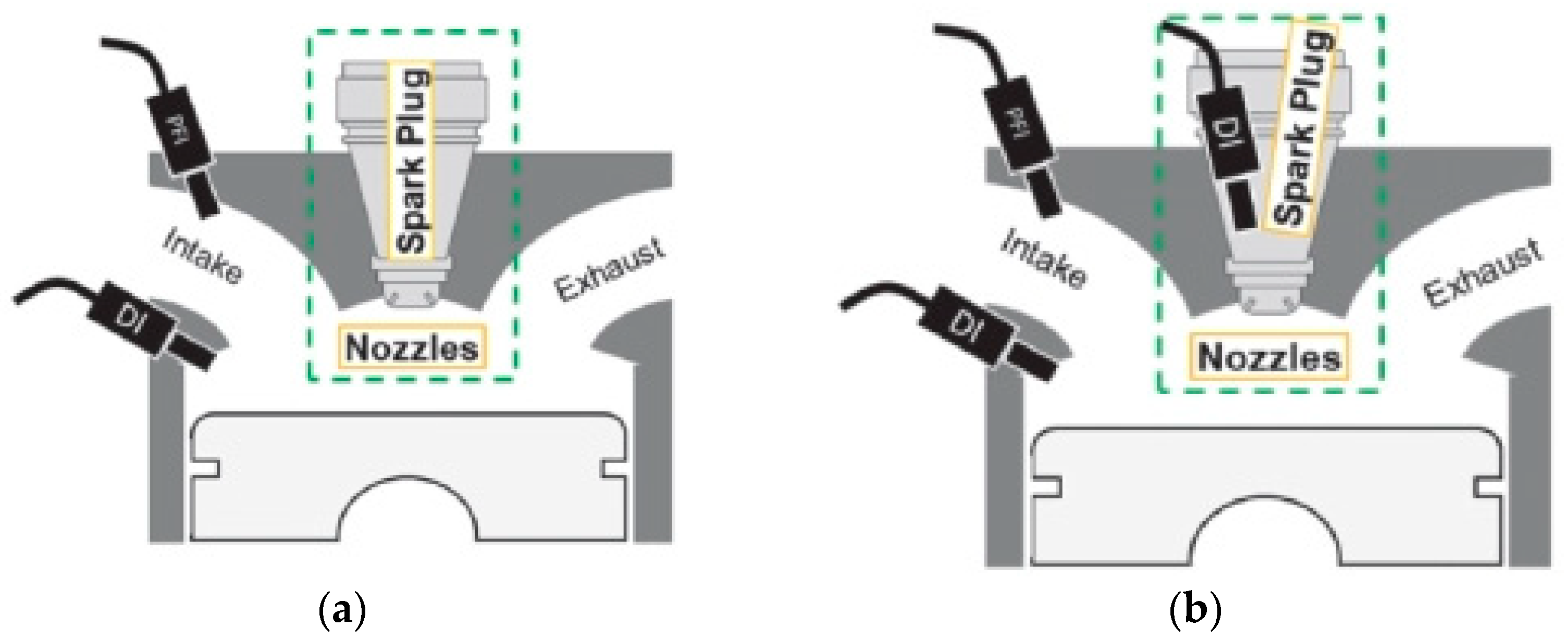
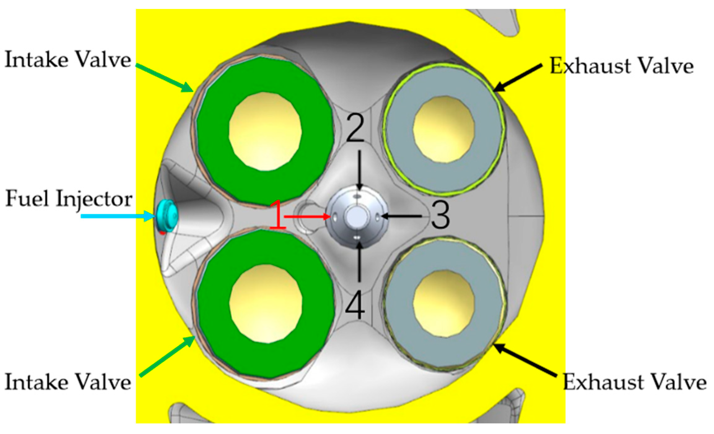
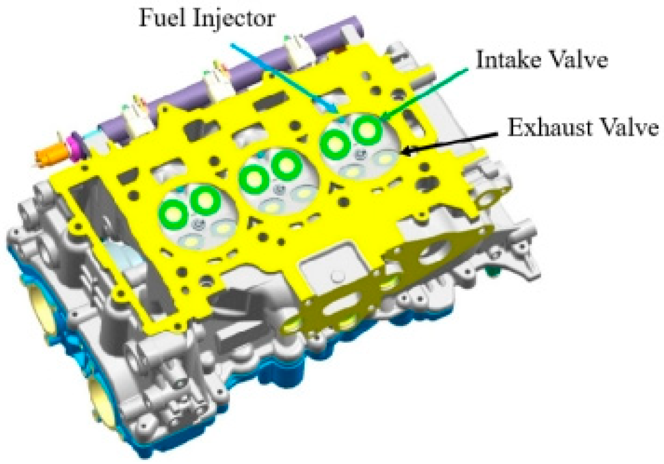
2.1. Experimental Engine

In this experiment, the engine is a turbo-charged direct-injection gasoline engine with a displacement of 1.0 L, a maximum injection pressure of 35 MPa, a three-time injection function, and an integrated water-cooled EGR system. The engine performance reaches China Stage 6 Limits. Its characteristic parameters are shown in Table 1.

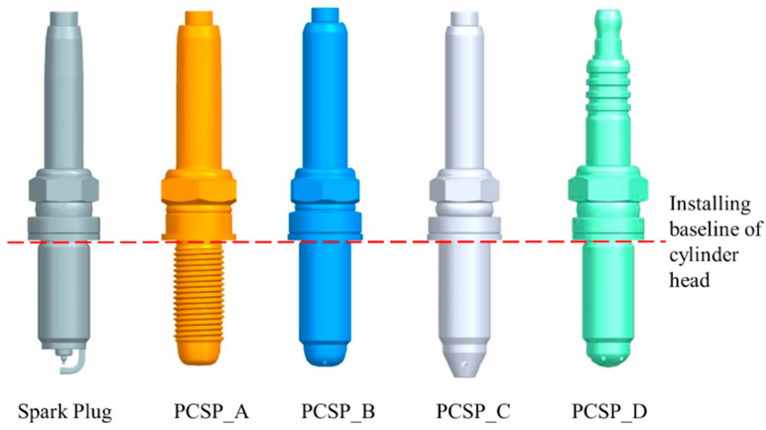
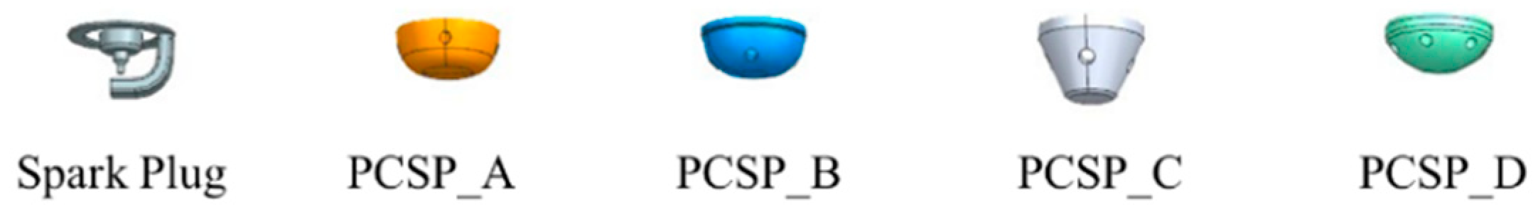
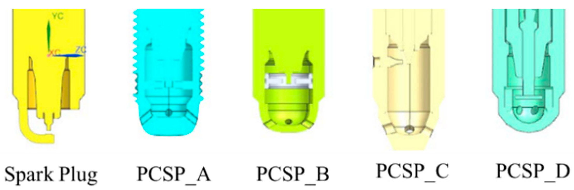
2.2. Pre-Chamber Spark Plugs
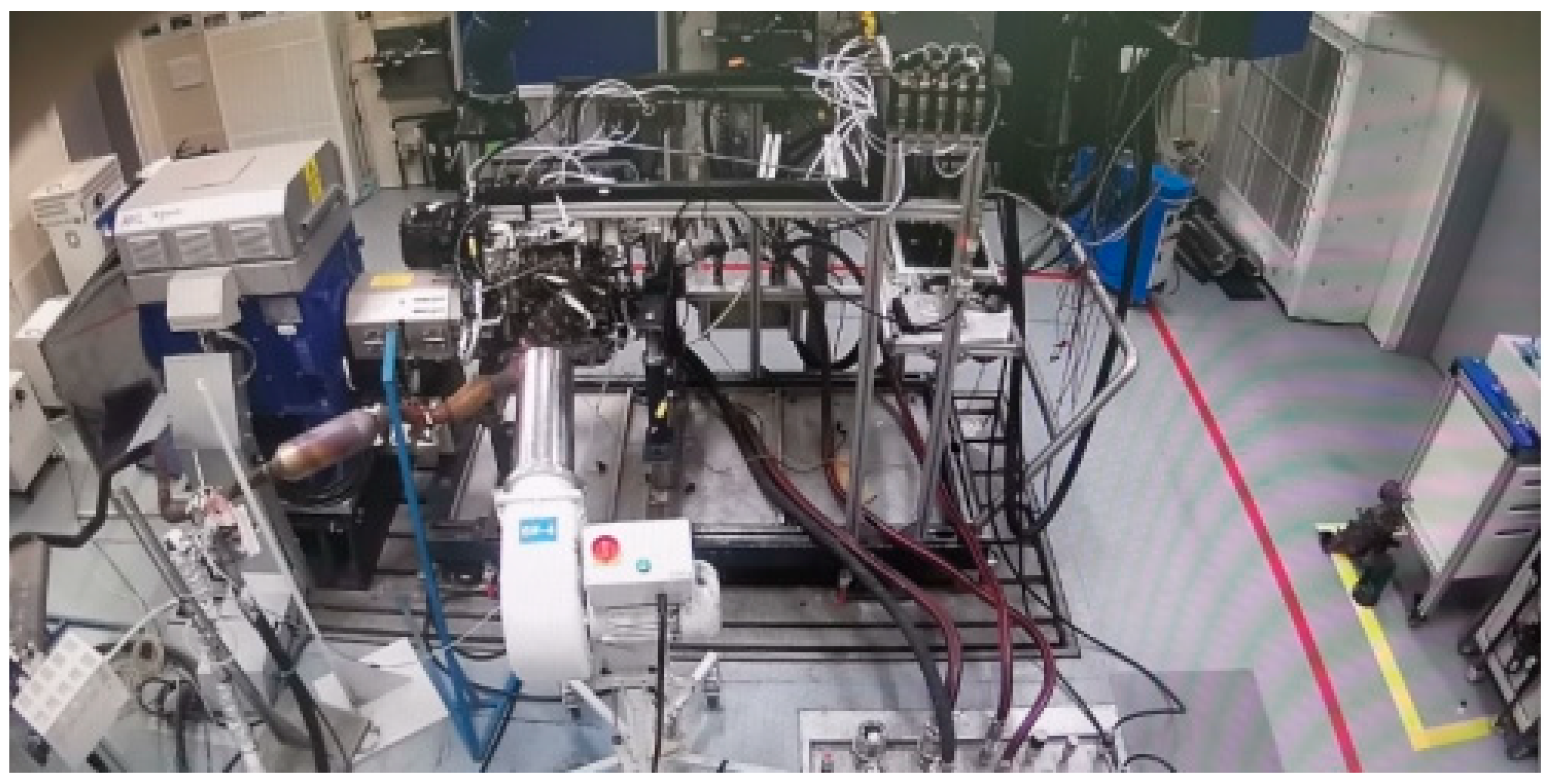
A total of five types of spark plugs were used in the experiment, including conventional spark plugs and four types of pre-chamber spark plugs. These different pre-chamber structures were representative designs obtained after analysis.
Figure 2 shows five types of spark plugs arranged simultaneously on the cylinder head mounting datum to show the exterior characteristics of different spark plugs.
Figure 3 shows the firing section structures of the five types of spark plugs. For pre-chamber spark plugs, the head configuration is the pre-chamber design feature. Pre-chamber spark plugs A, B, C, D have a separate chamber at the tip of the firing end compared with conventional spark plugs.
Figure 4 shows the electrode design of these five spark plugs. The electrode characteristics of different spark plugs are obtained by vertical cross-sectioning along the mounting axis of the spark plugs. We can see that pre-chamber A and B have two ground electrodes inside the pre-chamber and C has only one ground electrode, while D has NO ground electrode.
Table 2 shows the structural characteristics of the five types of spark plugs in the experiment.
Figure 5 shows the relative positions of spark plugs, injectors, intake valves, and exhaust valves on the cylinder head. As shown here, this experimental engine is designed with four valves per cylinder and side-mounted injectors.

2.3. Test Setup

Figure 6 shows the layout of the experimental bench to investigate the performance of a turbo-charged direct-injection gasoline engine based on different pre-chamber structures, and the list of measurement equipment used for the experiments is shown in Table 3.
The ambient temperature of the laboratory was controlled at 25 ± 3 °C. The water temperature was 90 ± 5 °C. The oil temperature was 85 ± 5 °C, and the upper limit of the catalytic converter temperature at 950 °C. During the experiments, the EGR rate was measured based on the data from the emission analyzer.
The environment parameters are controlled in standard conditions by the test cell, and the different spark plugs are tested under the same environment parameters.
The manufacturer of dynamometer, control system, fuel cosumption meter, oil/cooling trolley is AVL (Graz, Austria). The manufacturer of Emission Analyzer and PN Analyzer is HORIBA (Kyoto, Japan).

2.4. Test Conditions and Methods

The experiments were conducted in the AVL Power Dynamometer Bench Lab under multi-operating conditions, specified as follows:
(1)
Load characterization tests were performed at 2000 r/min speed; the load started from BMEP 2 bar up to 20 bar and WOT condition.
(2)
Characteristic point tests were performed at 3000 r/min speed; the characteristic point loads were BMEP 10 bar and 20 bar, respectively.
(3)
Characteristic point tests were conducted at 3200 r/min speed; the characteristic point load at 3200 r/min was BMEP 12 bar, which is the optimum fuel consumption point.
(4)
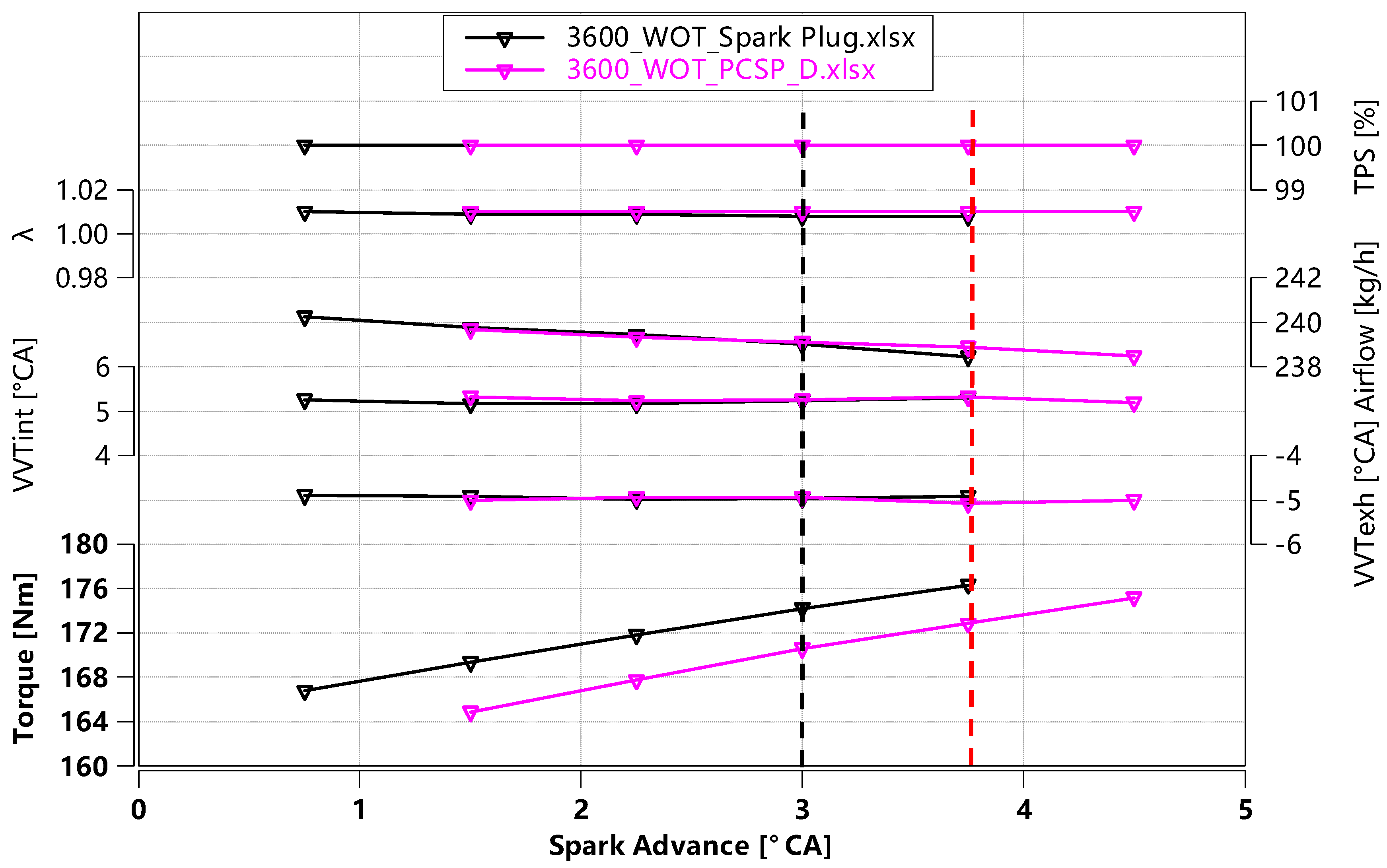
Spark angle scans for WOT conditions were performed at 3600 r/min speed to compare the dynamics performance of pre-chamber spark plug D and conventional spark plug.
In order to study the effect of different pre-chamber structures on engine performance, attention needs to be paid to the assembly of various spark plugs on the cylinder head. To ensure the relative consistency of the mounting height of various types of spark plugs on the cylinder head, the gaskets of the spark plugs were uniformly set. All types of spark plugs, including conventional spark plugs and pre-chamber spark plugs, use copper gaskets with a height of 1.5 mm, similar to the cylinder pressure spark plugs, and at the same time, they adopt a uniform installation torque. The ignition position of the spark plugs is kept consistent after installation on the cylinder head so as to avoid additional disturbances caused by differences in gaskets or installation torques.
For the passive pre-chamber, if the jet holes are evenly distributed and the centerlines of the spark plug mounting position and that of the cylinder coincide, the uniform arrangement of the jet flame in the cylinder after installation will create smaller impacts. However, if the above conditions are not met, the spatial distribution of the jet flame in the cylinder after installation will turn out to be more complicated.
In this study, the jet holes of pre-chamber spark plug C are not evenly distributed mainly due to the non-uniform diameters of the four jet holes, which are labeled as 1#, 2#, 3#, and 4# in sequence, where 1# is a large hole with a diameter of 1.75 mm, and 2#, 3#, and 4# are small holes with a diameter of 1.5 mm. In order to make full use of the gas flow in the cylinder to promote exhaust gas sweeping inside the pre-chamber and to improve the reliability of injection ignition, it is necessary to use a thin gasket with a 0.5 mm thickness and repeatedly adjust the installation torque to ensure the alignment of hole 1# with the intake side in the assembly process.
Figure 7 shows the installation of the pre-chamber spark plug C. The diameter of the larger jetting hole 1# is 1.75 mm, which is facing the intake side as in the figure. The other three smaller holes’ diameter is only 1.5 mm, which is marked as 2#, 3#, 4# in Figure 7. After completing the proper installation of the various spark plugs on the cylinder head, bench tests were carried out following the steps below.
Firstly, the external characteristics of the engine were tested to ensure its normal functioning.
Secondly, with the use of conventional spark plugs, experiments were conducted at multiple speeds and loads; during the experiments, BMEP was kept stable, and spark angle sweeping was conducted. For non-burst conditions, the optimal torque point—MBT point—was used as the sweeping target, and for burst conditions, the KBL point—the boundary point of the burst—was used as the sweeping target.
Next, the above experiments were repeated using spark plugs A, B, C, D with different pre-chamber structures in sequence.
Finally, the data were organized and analyzed.
It should be noted that the experiments in this study were carried out on the product engine for its reliable hardware and calibration and stable performance, which means that the impact of pre-chamber spark plugs on engine performance is closer to engineering practice. However, the shortcomings include small engine single-cylinder displacement and limited space on the engine, meaning that the cylinder pressure sensor cannot be fixed onto the cylinder head, except for the original spark plug. Thus, data regarding the combustion analyzer were unavailable. In this study, the acceleration sensor was used to monitor the vibration, and the speaker was adopted for the real-time monitoring of engine operation, especially vibration under heavy load conditions.
The fuel grade used in this study is RON 92.

3. Test Results Analysis

3.1. Dynamic Performance Analysis

Given that the external characteristic torque of an engine is a major indicator of its dynamics, this paper studies the dynamics of different pre-chamber structures based on external characteristic torque. In the external characteristic experiment, the pedal APS and throttle valve plate TPS were kept fully open; the air–fuel ratio was kept at the theoretical air–fuel ratio, i.e., the excess air coefficient λ = 1; the injection opening moment was unified with the closing moment; and the VVTint and VVTexh positions were constant. Under these conditions, the spark angle scan was carried out to obtain the variation curves of the external characteristic torque along with the spark angle.
Figure 8 shows the external characteristics at 2000 r/min, which apply to pre-chambers A, B, and C. The experimental external characteristics of pre-chamber D are presented at 3600 r/min, as shown in Figure 9.
The external characteristics at 3600 r/min in Figure 9 include conventional spark plug and pre-chamber spark plug D.
In order to make a comparison of the dynamics under different pre-chamber structures, two dashed lines in black and red are added as reference lines in Figure 8 and Figure 9, from which the following conclusions are derived:
(1)
As shown in the performance data at the red dashed line in Figure 8, the dynamics of the pre-chamber spark plug meet the external characteristic torque requirements. Its power is increased by 1.6% relative to a conventional spark plug.
(2)
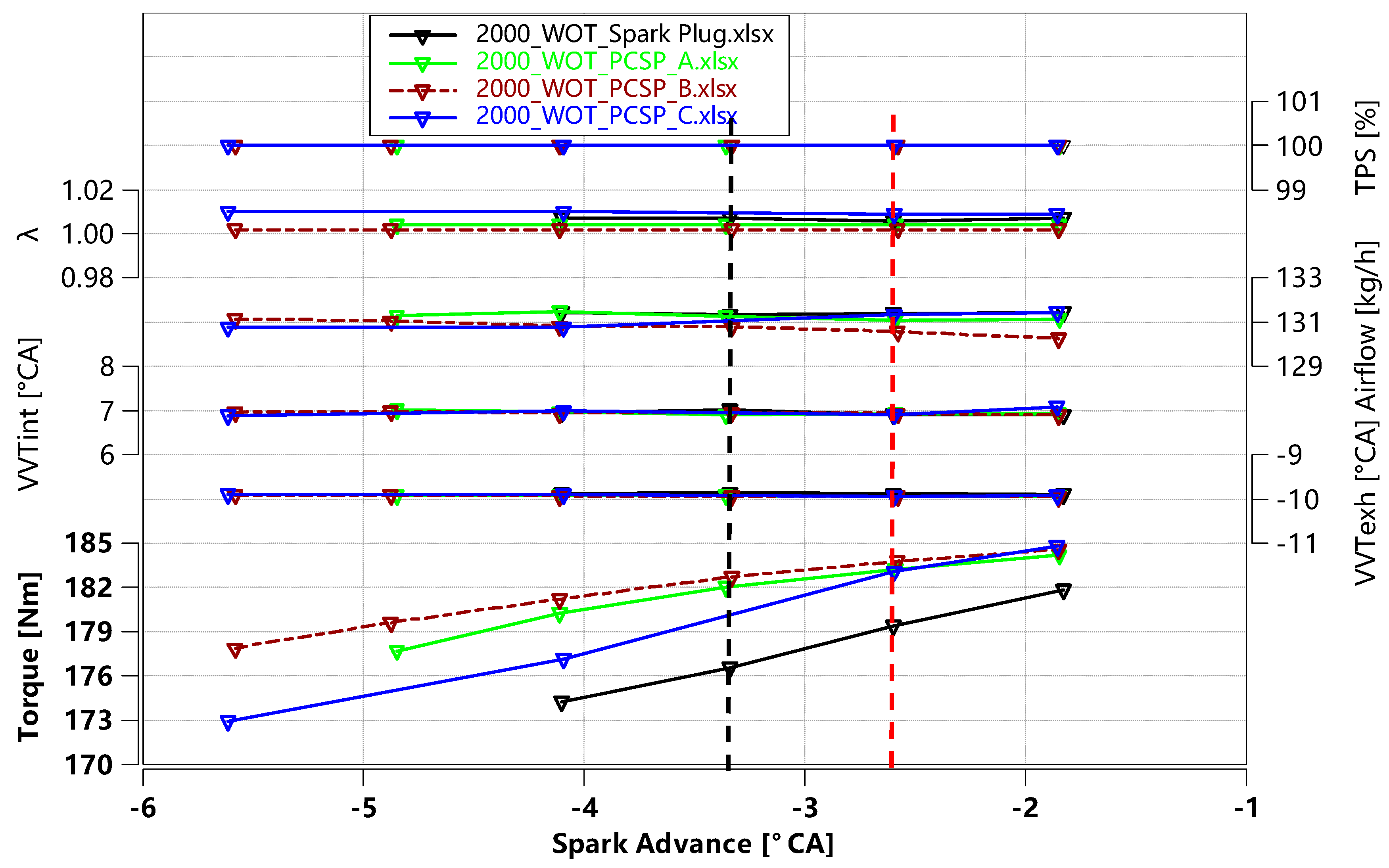
Combining the performance data at the black dashed line shown in Figure 8 and Figure 9, the power under the same spark angle conditions is ranked as follows: B > A > C > Base > D, i.e., pre-chamber spark plugs B, A, and C are more powerful, and D is slightly less powerful compared with conventional spark plugs.
Based on the above analysis, in-cylinder flow under the external characteristic condition is strong, the gas in the main combustion chamber has a significant sweeping effect on the residual exhaust gas in the pre-chamber, and the ignition reliability is high. At the same time, the space jet ignition mode of the pre-chamber ignition accelerates the combustion speed in the main combustion chamber, which, in turn, improves the pre-chamber spark plug dynamics.
As can be seen from Table 2, the structures of the four pre-chambers are different, which are reflected in the design of ground electrodes, the volume of the pre-chamber, and the number and diameter of jet holes. Considering the perspective of the ground electrode, only pre-chamber D does not have a separate ground electrode. Instead, the wall inside the pre-chamber is used as the ground electrode, as shown in the sectional view in Figure 3 and Figure 4. In terms of the ignition principle, under the same dielectric density, voltage breakdown occurs first at the place with the shortest path. Therefore, the smooth inner wall surfaces of the ground electrodes can become the ignition voltage breakdown point in pre-chamber D. This non-fixed ignition voltage breakdown point can lead to varying distances between the ignition point generated within the pre-chamber and the jet holes of each pre-chamber. This will bring about inconsistency at the moment when the jet flame in the pre-chamber enters the main combustion chamber, further causing poor combustion in the main combustion chamber and affecting the dynamics of the engine. Turbulence Kinetic Energy (TKE) in the pre-chamber is extremely important to combustion in the main chamber. Therefore, the root cause of the slightly poorer power of the pre-chamber spark plug D lies in poor TKE and then poor combustion, which is largely determined by the ground electrode design.

3.2. Economic Analysis

As the specific fuel consumption of an engine is a major reflection of its economy, this paper studies the economy of different pre-chamber structures based on their specific fuel consumption. For a comprehensive comparison, three loads of 2 bar, 8 bar, and 16 bar at 2000 r/min are selected for economic analysis.

3.2.1. Economy of 2000 r/min and BMEP 2 bar

The following conclusions can be drawn from Figure 10.
(1)
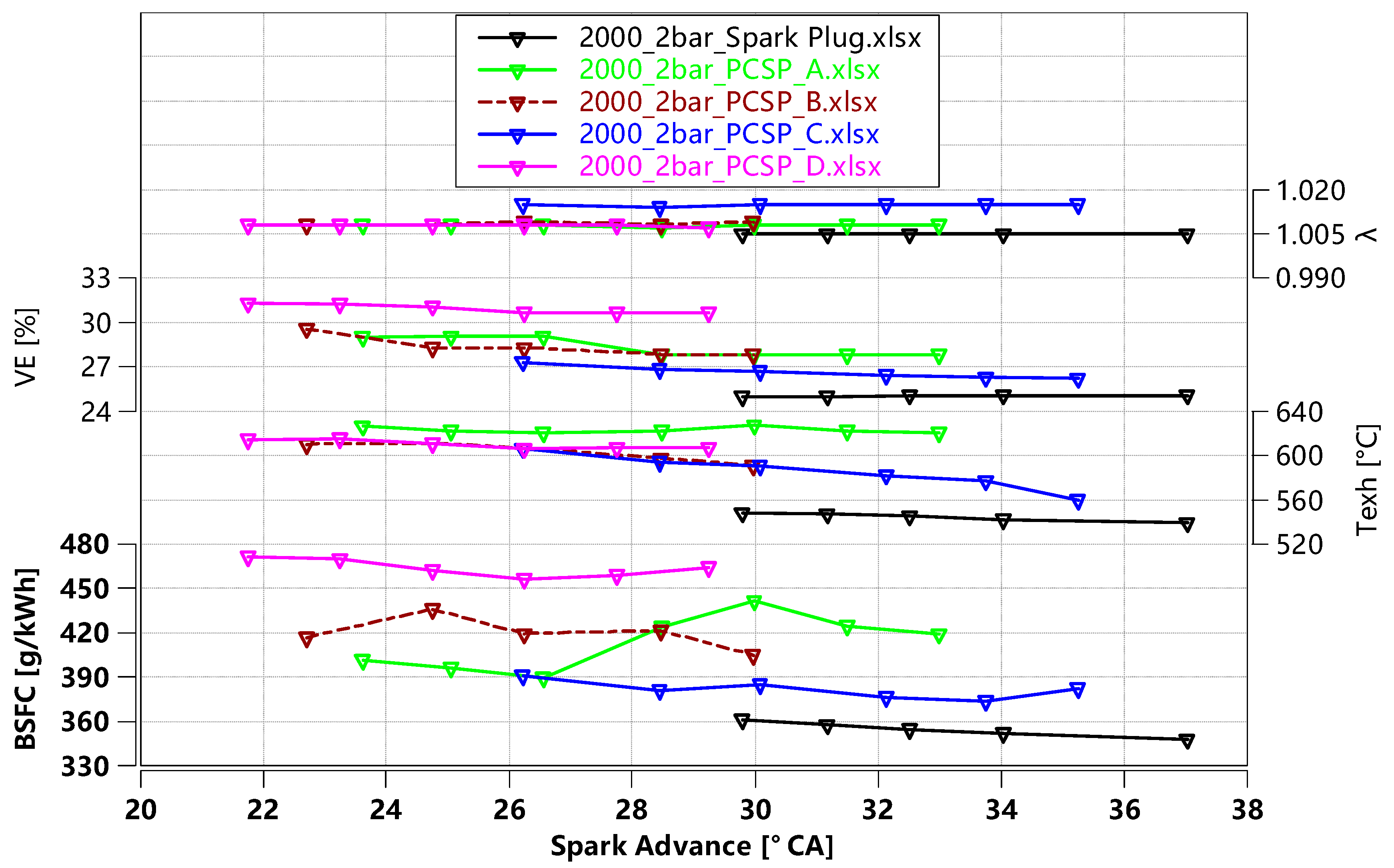
At a 2 bar load, the fluctuations in the mean effective pressure and relative charge Volumetric Efficiency (VE) of the pre-chamber spark plugs are significantly larger, and the specific fuel consumption is significantly higher compared to the conventional spark plugs.
(2)
At a 2 bar load, the exhaust temperature of pre-chamber spark plugs is higher than that of conventional spark plugs.
(3)
At a 2 bar load, the economy of the four pre-chamber spark plugs is ranked as C > A > B > D, i.e., the fuel economy of pre-chamber C is the best, and that of D is the worst.
(4)
Although pre-chamber C has the best BSFC among the pre-chamber spark plugs, it is still with a 6% deterioration of BSFC. It is a long way from a conventional spark plug.
Based on the above analysis, the flow in the cylinder under the 2 bar condition is weak, and the gas in the main combustion chamber does not have a significant sweeping effect on the residual exhaust gases in the pre-chamber. The ignition lagging period is long, the combustion phase lags, and the exhaust temperature rises, as confirmed by the exhaust temperature curves in Figure 10.
The economy of pre-chamber spark plugs A, B, C, and D were analyzed. Pre-chambers A, B, and C have separate ground electrode designs, as shown in the cross-section in Figure 4. The difference lies in that the pre-chamber A and B have two ground electrodes, while pre-chamber C has only one ground electrode. The design of two ground electrodes inside the pre-chamber is based on the ignition principle that with comparable dielectric density, the voltage breakdown occurs first in the place with the shortest path that is easy to break down. Therefore, the design of two ground electrodes can improve the stability of ignition. However, the pre-chamber has a narrow internal volume, accounting for less than 5% of the whole combustion chamber volume. Compared with pre-chamber C with only one ground electrode, the extra ground electrode in pre-chamber A and B is not favorable for internal sweeping and flame growth, especially at a small load of 2 bar. Even with two ground electrodes, for each specific ignition event, the breakdown occurs only on one of the ground electrodes, and the other ground electrode will hinder flame growth in the small space. Therefore, the design of two ground electrodes is not conducive to jet flame growth inside the pre-chamber, resulting in lower economy in pre-chamber A and B than in pre-chamber C. In addition, the diameter of jetting holes helps improve the economy of pre-chamber C. The jetting holes of pre-chamber C and their arrangement on the engine are featured by a large diameter near the intake side and a small diameter near the exhaust side. This is conducive to fully utilizing the in-cylinder gas flow field to sweep the pre-chamber during the intake stroke, reducing the residual exhaust gas coefficient inside the pre-chamber and lowering the probability of misfire, which is useful for controlling COV and beneficial for improving the economy of pre-chamber ignition.
The reason for the unsatisfying economic performance of pre-chamber spark plug D arises from poor combustion, which is largely due to ground electrode designs.

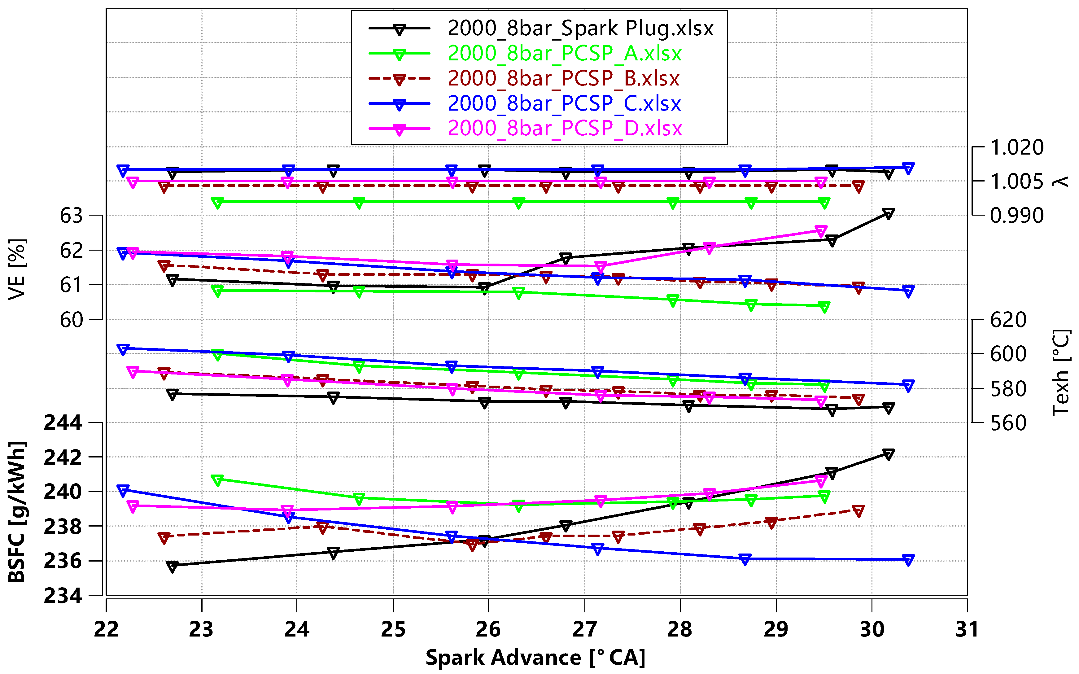
3.2.2. Economy of 2000 r/min and BMEP 8 bar

The following conclusions can be drawn from Figure 11.
(1)
Compared to 2 bar load, the range of fluctuations in the mean effective pressure and relative charge of pre-chamber spark plugs and the difference in specific fuel consumption relative to ordinary spark plugs were significantly reduced.
(2)
The economy of the four pre-chamber spark plugs is ranked as C > B > A > D, i.e., the fuel economy of pre-chamber C is the best, and that of D is the worst.
(3)
The economy of pre-chamber C is the best among the pre-chamber spark plugs, reaching a level comparable to that of conventional spark plugs.
As the above analysis shows, compared to a 2 bar load, the flow in the cylinder at an 8 bar load is enhanced, and the gas in the main combustion chamber effectively sweeps the residual exhaust gas in the pre-chamber. Ignition reliability is improved, with a significantly lowered possibility of engine misfire and poor combustion and reduction of specific fuel consumption, which contributes to the improvement of fuel economy.
The underperformance of spark plug D in the pre-chamber at an 8 bar load is largely due to the ground electrode design. Better fuel consumption in pre-chamber C, as aforementioned, is attributable to the fact that its structural design helps make full use of the in-cylinder gas flow field to sweep the pre-chamber during the intake stroke, reducing the residual exhaust gas coefficient inside the pre-chamber and lowering the probability of misfire, which can further enhance the economy of pre-chamber ignition.

3.2.3. Economy of 2000 r/min and BMEP 16 bar

Figure 12 shows the trend of engine performance index changes in relation to spark advance angle at 2000 r/min–16 bar.
The following conclusions can be drawn from Figure 12.
(1)
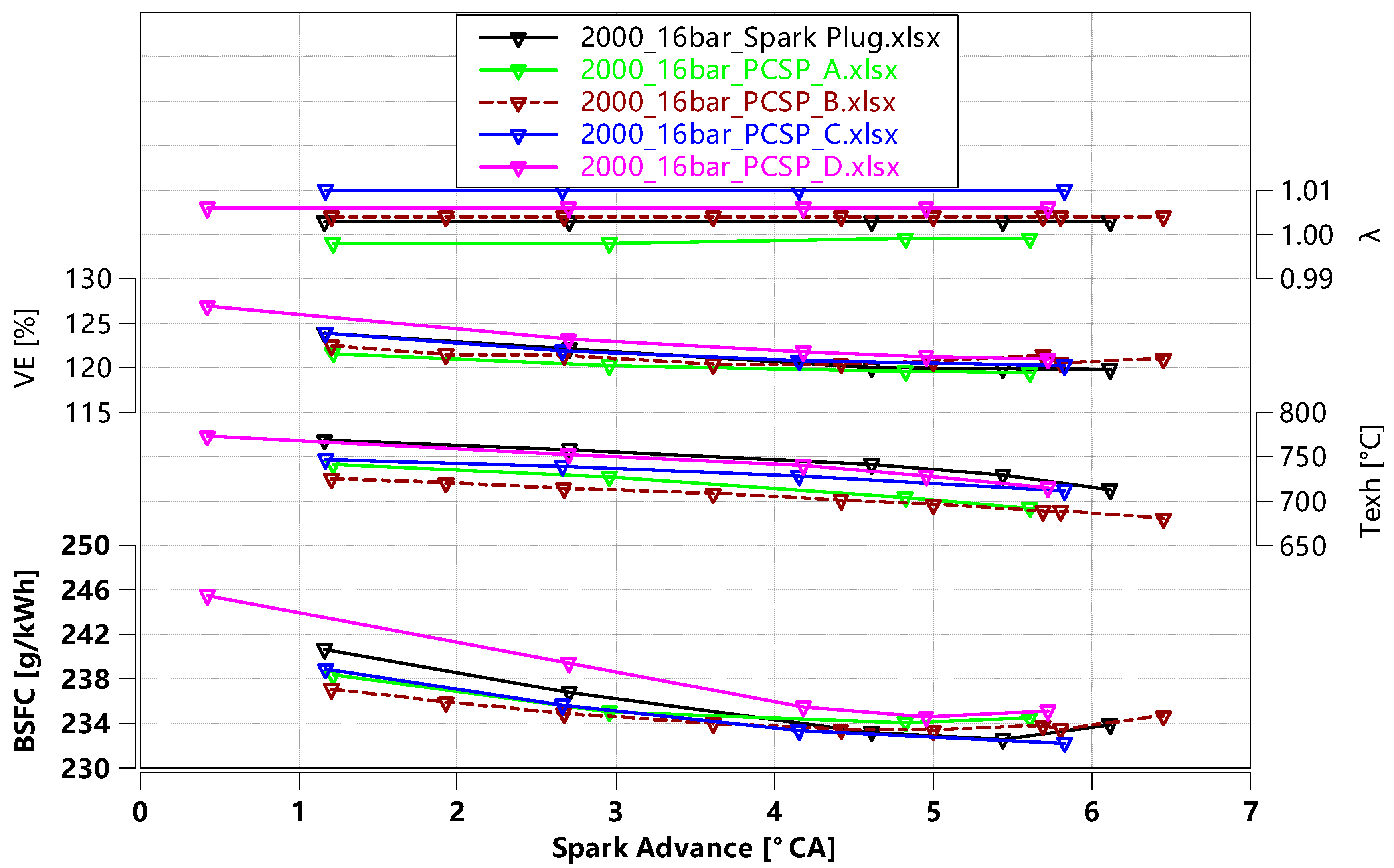
At this load, pre-chamber spark plugs outperform conventional spark plugs.
(2)
Similar to that at 2 bar and 8 bar loads, the fuel consumption of pre-chamber C remains the best, and that of pre-chamber D is the worst.
Therefore, it can be concluded that at a 16 bar load, the flow in the cylinder is strong, and the gas in the main combustion chamber has a remarkable sweeping effect on the residual exhaust gas in the pre-chamber, with high ignition reliability. Meanwhile, the space jet ignition mode in the pre-chamber accelerates the combustion speed in the main combustion chamber, which further improves the economy of pre-chamber spark plugs.
The following conclusions are reached based on the results of Figure 10, Figure 11 and Figure 12.
The effect of pre-chamber jet ignition technology on engine economy is related to the load. As the load increases, the advantages of pre-chamber jet ignition in terms of fuel economy become apparent, specified as follows.
(1)
At a small load like 2 bar, the ignition economy of the pre-chamber is not as satisfactory as that of conventional spark plugs, with a 6% difference.
(2)
At a medium load like 8 bar, both are economically comparable.
(3)
At a large load like 16 bar, the fuel economy of the pre-chamber is more satisfactory.

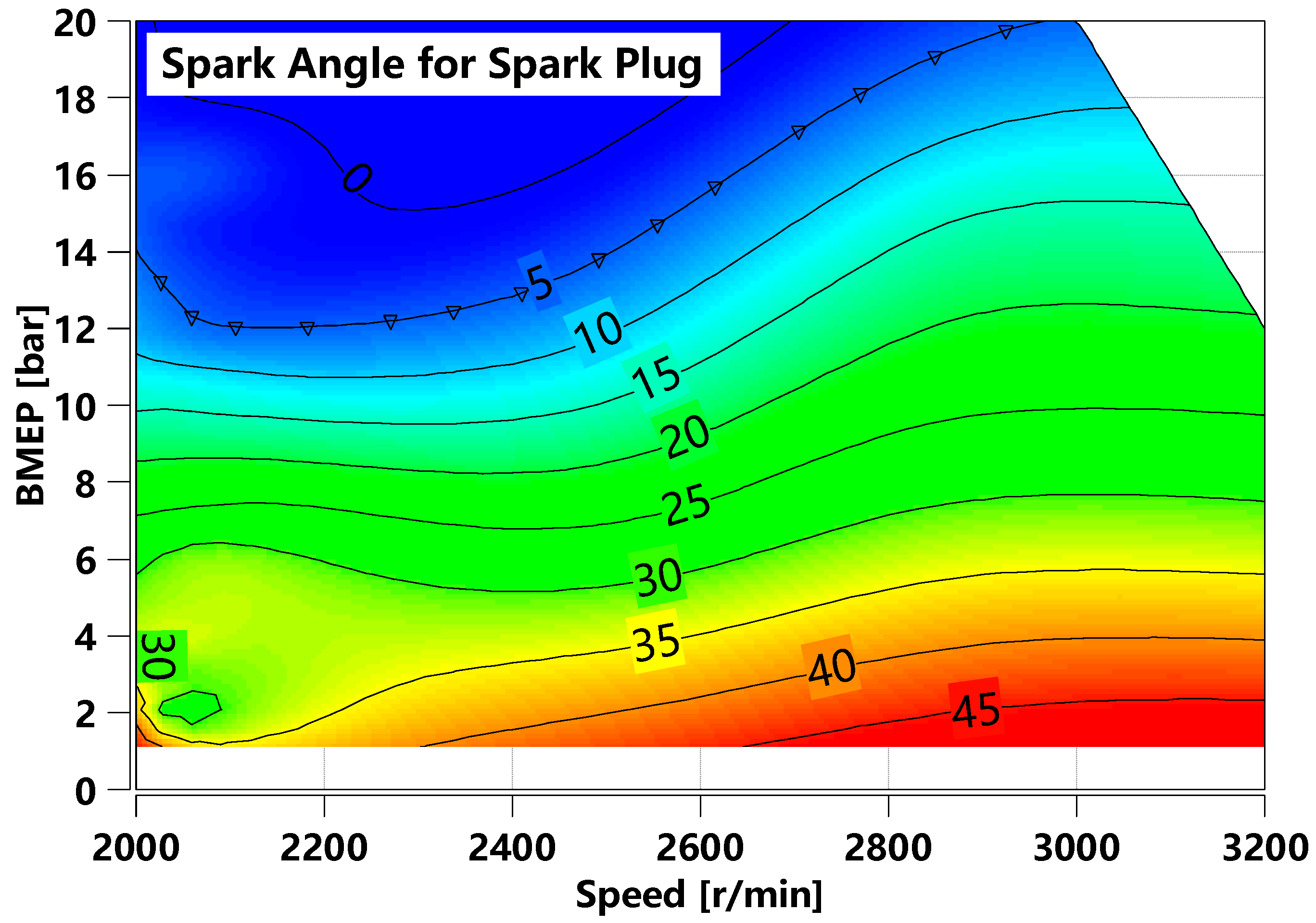
3.2.4. Engine Spark Angle MAP Diagram

As mentioned earlier, the cylinder pressure sensor was not used in this test and the combustion analyzer parameters could not be used as combustion boundaries. Instead, the acceleration sensor signal and the burst speaker signal were used as the burst boundary and combustion boundary for spark angle scanning at different speeds and loads. Specific fuel consumption was utilized for determining the optimal spark angle for each operating condition.
It should be noted that the large load boundary in the spark angle MAP diagram was set at 20 bar for the purpose of consistency.
As shown in Figure 13 and Figure 14, the spark angle is analyzed based on the coordinate axes of speed and load, and the spark angle contour is drawn. Additionally, to facilitate the comparison between the conventional spark plugs and the four types of pre-chamber spark plugs, A, B, C, and D, the 5 °CA spark angle contour was used as a marker, indicated by a thickened curve.
Combining Figure 13 and Figure 14, the following pattern can be identified.
(1)
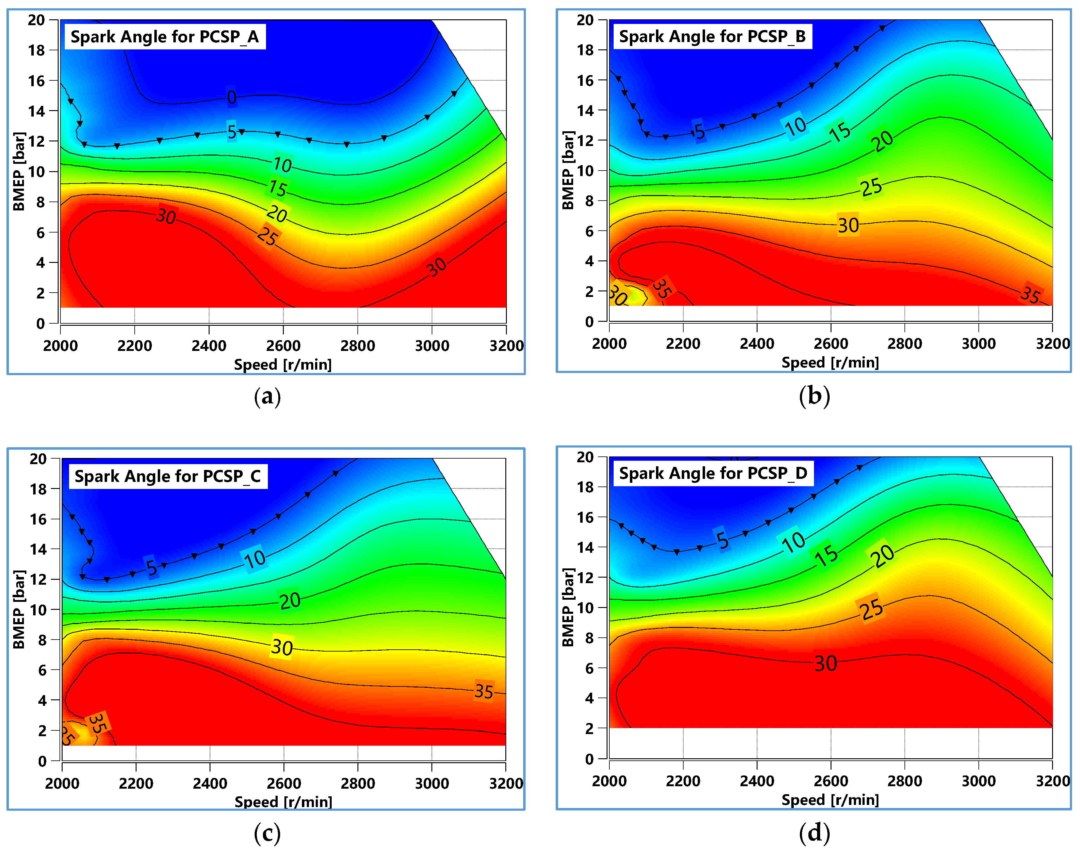
The spark angle change pattern of pre-chamber spark plugs is similar to that of conventional spark plugs; i.e., under the same rotational speed, the small load corresponds to the large spark angle, the large load corresponds to the small spark angle, and the spark angle decreases with the increase in load, which is in line with the general law of engines. This is due to the fact that the pre-chamber volume generally accounts for less than 5% of the whole combustion chamber volume, and pre-chamber combustion only stands as the source for the main combustion chamber, with the latter as the major area for cylinder combustion.
(2)
For conventional spark plug, the spark angle is 5 °CA at 2000 r/min and 14 bar, while for pre-chamber spark plugs, the same spark angle corresponds to a load of 16~17 bar, which means that the spark angle can be advanced for pre-chamber spark plugs. Through analysis, the spark angle of pre-chamber spark plugs can be advanced by 2~3 °CA relative to conventional spark plugs.
(3)
For pre-chamber spark plugs, in terms of the 30 °CA spark angle contour located in the low- and medium-load area, it can be seen that the 30 °CA contour of pre-chamber C occupies the largest proportion of the working area, followed by pre-chamber B, D, and A in a declining order. This shows that under the same conditions, pre-chamber C features a larger spark angle at the same rotational speed and load. Combined with the structure of pre-chamber C and the orientation of its jet holes in the engine, the design of the pre-chamber structure needs to take into account the direction of the in-cylinder airflow and needs to be matched with the design of the combustion chamber.

3.2.5. Engine Fuel Economy MAP Diagram
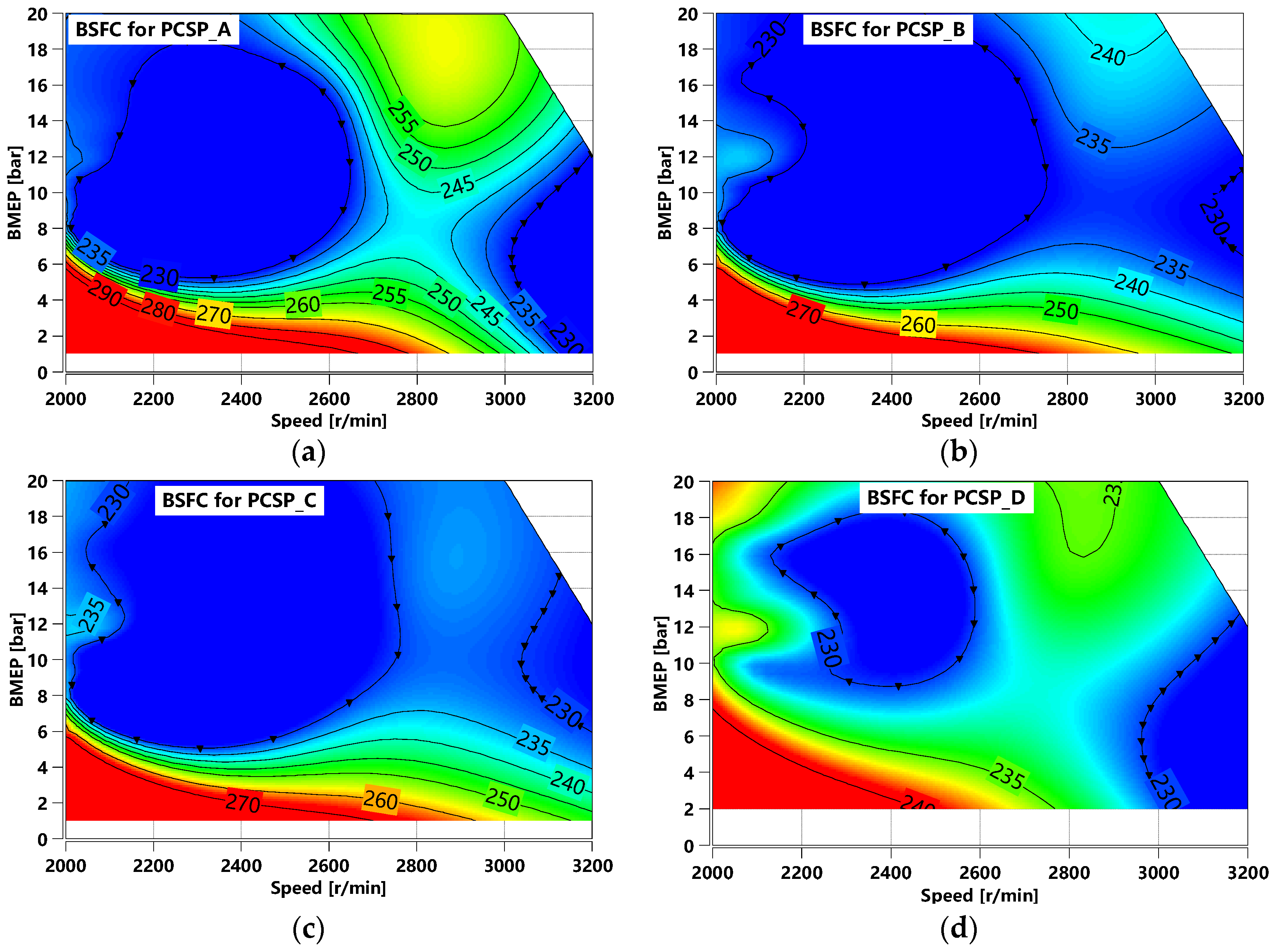
The specific fuel consumption is used as an indicator for economic analysis. As shown in Figure 15 and Figure 16, a specific fuel consumption contour is drawn on the basis of the coordinates of speed and load. Meanwhile, in order to facilitate the comparison between the conventional spark plugs and the four types of pre-chamber spark plugs A, B, C, and D, the 230 g/kWh contour is used as a marker line, which is indicated by a thickened black line made using a marker. The following pattern can be clearly derived from Figure 15 and Figure 16.
(1)
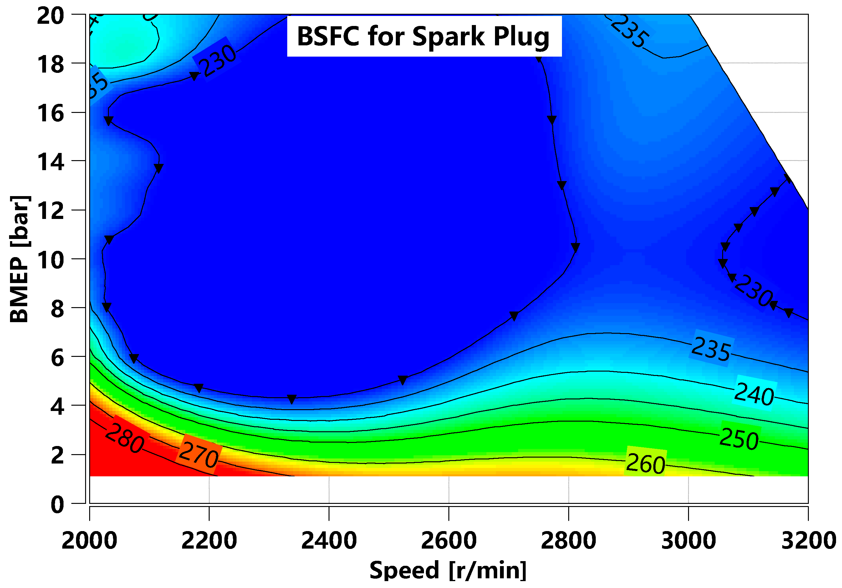
As shown in Figure 16, pre-chamber C has the largest area enclosed by the 230 g/kWh contour, and pre-chamber T is the smallest. The areas enclosed by the spark plugs of the four pre-chambers are ranked as C > B > A > D. Therefore, in terms of the economy represented by the specific fuel consumption, the economy of the four pre-chamber structures is ranked as C > B > A > D. This is consistent with the results of the pre-chambers at 2000 r/ min and 8 bar.
(2)
To analyze the economy of the spark plugs of pre-chamber C and conventional spark plugs, the 230 g/(kW·h) specific fuel consumption curve is still used as a reference. Figure 15 shows that the 230 g/(kW·h) curve is close to 5 bar through the low-load region of the conventional spark plugs. Figure 16c indicates that the 230 g/(kW·h) curve is close to 6 bar through the low-load region of pre-chamber C. Thus, for the low-load region, the pre-chamber spark plugs are less economical than the conventional ones. Based on the distribution pattern of specific fuel consumption contour, it can be seen that this gap is 5~10 g/(kW·h) in the low-load region. Similarly, the economy at 20 bar in the high-load region is analyzed. From Figure 16, the fuel consumption curve of pre-chamber spark plug C crosses the speed range roughly from 2100 r/min to 2700 r/min, while that of the conventional spark plug covers the speed range roughly from 2400 r/min to 2700 r/min. It can be concluded that the speed range covered by the pre-chamber spark plug C is wider than that of the conventional spark plug, i.e., the economy of pre-chamber spark plug C is better than that of the conventional spark plug in the high-load region.
The pre-chamber structure can be examined for economic analysis. According to the previous analysis, the poor economic performance of pre-chamber spark plug D is rooted in poor combustion, which is largely due to the design characteristics of the ground electrodes. The structure of pre-chamber C is conducive to making full use of the in-cylinder gas flow field in the intake stroke to sweep the pre-chamber, reducing the residual exhaust gas coefficient inside the pre-chamber and lowering the probability of misfire, which is important for improving the reliability of pre-chamber ignition and economy.
The reason for the difference in economy can be analyzed from the principle of ignition in the pre-chamber. Under small load conditions, the flow in the cylinder is weak, and the gas in the main combustion chamber is not effective in sweeping the residual exhaust gases in the pre-chamber, which may easily cause misfire, resulting in poor combustion and poor economy. Under large load conditions, the flow in the cylinder is enhanced, and the gas sweeping effect of the main combustion chamber on the residual exhaust gases in the pre-chamber is improved, which increases ignition reliability; at the same time, the spatial jet ignition mode of the pre-chamber ignition accelerates the combustion speed in the main combustion chamber, which improves the economy of the pre-chamber spark plug C.

3.3. Emission Characteristic Analysis

The emission characteristic analysis, following the working conditions of the economic analysis, was carried out by selecting BMEP of 2 bar, 8 bar, and 16 bar at 2000 r/min and examining THC, CO, NOx, and PN.

3.3.1. THC Emission Characteristics
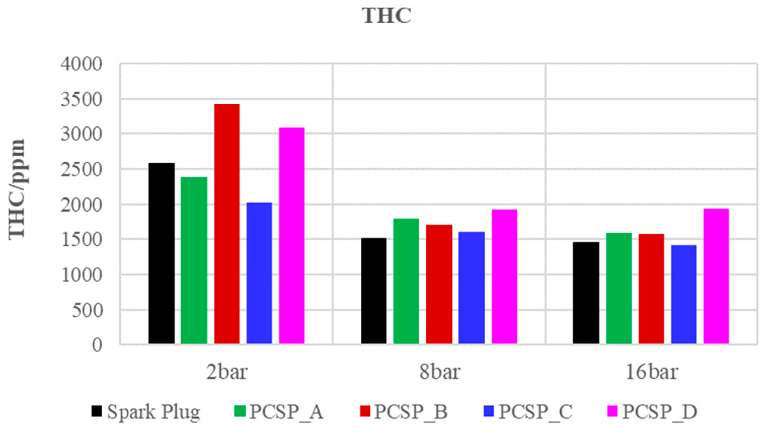
Figure 17 shows the THC emission characteristics for different pre-chamber structures, from which the following conclusions can be drawn:
(1)
THC emissions are load-dependent and significantly higher at small loads than at medium and large loads.
(2)
THC emissions from the pre-chambers are overall comparable to those of conventional spark plugs.
(3)
THC emissions of pre-chambers with different structures are similar, with pre-chamber C having the lowest THC emissions at all loads.
Regardless of pre-chambers or conventional spark plug, the in-cylinder flow is weak at 2 bar load, with a higher proportion of residual exhaust gas volume in the combustion chamber and poor ignition reliability, which is likely to result in poor combustion of the engine, a strong in-cylinder residual gap effect, and a rise in THC emissions. When the engine is operated at a medium or large load, the flow in the cylinder is enhanced, with a lower proportion of residual exhaust gas and improved ignition reliability and combustion stability, contributing to reduced THC emissions.
With reference to the economy analysis, the characteristics of the pre-chamber structure bring forth low THC emissions from pre-chamber C.

3.3.2. CO Emission Characteristics
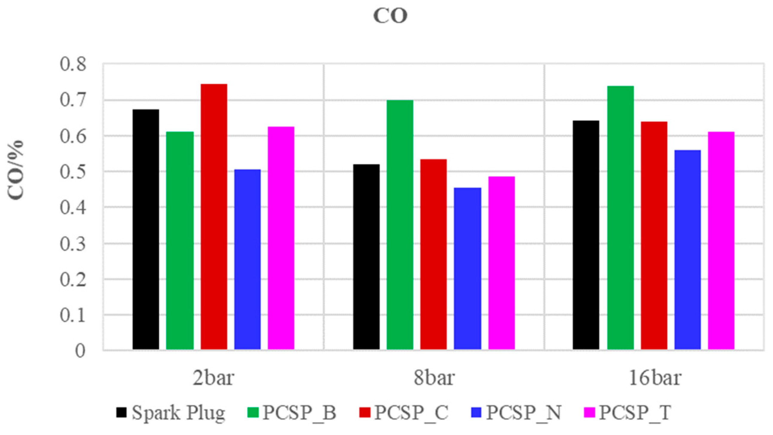
Figure 18 shows the CO emission characteristics of different pre-chamber structures, from which the following conclusions can be drawn:
(1)
CO emissions are independent of load, with no significant emission difference at small, medium, and large loads.
(2)
CO emissions from the pre-chambers are overall comparable to those of conventional spark plugs.
(3)
CO emissions of pre-chambers with different structures are similar, with pre-chamber N having the lowest CO emissions at all loads.
Based on the above analysis, CO production is mainly related to the air–fuel ratio and excess air coefficient. The experiments were carried out at the theoretical air–fuel ratio for all loads. Therefore, CO generation is stable at different loads.
With reference to the economy analysis, the characteristics of the pre-chamber structure bring forth low CO emissions from pre-chamber C.

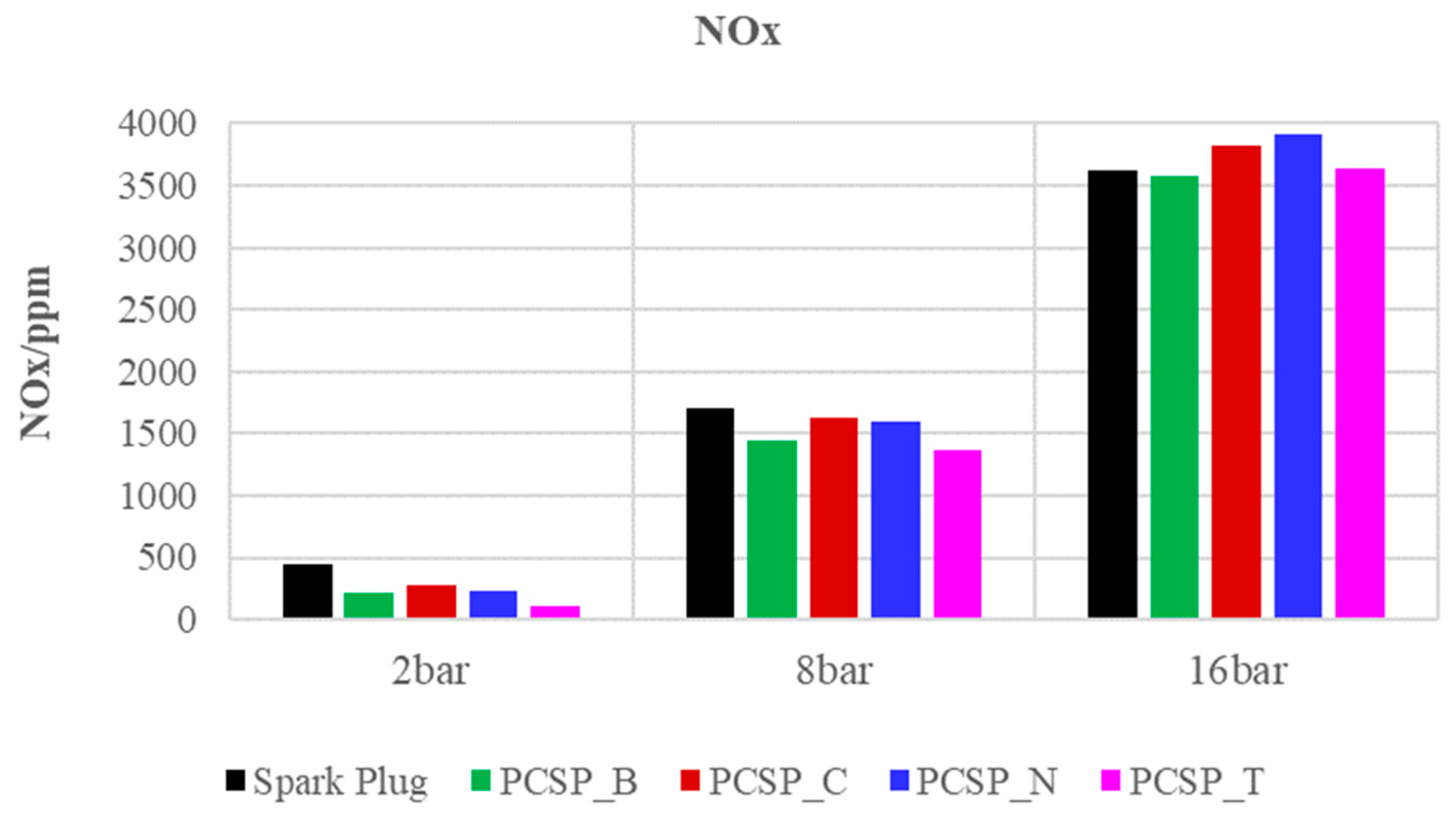
3.3.3. NOx Emission Characteristics

Figure 19 shows the NOx emission characteristics of different pre-chamber structures, from which the following conclusions can be drawn.
(1)
NOx emissions are strongly correlated with load and increase with load.
(2)
NOx emissions of pre-chambers are overall comparable to those of conventional spark plugs.
(3)
NOx emissions of different pre-chamber structures are similar.
Based on the above analysis, NOx emissions are mainly related to high temperature and oxygen enrichment. The experiments were carried out at the theoretical air–fuel ratio for all loads, with stable oxygen content in the cylinder. Therefore, NOx emissions are affected by temperature. As can be seen from the economy analysis data in Figure 10, Figure 11 and Figure 12, as engine load increases, the in-cylinder combustion temperature increases and the exhaust temperature rises, which favors NOx generation.

3.3.4. PN Emission Characteristics
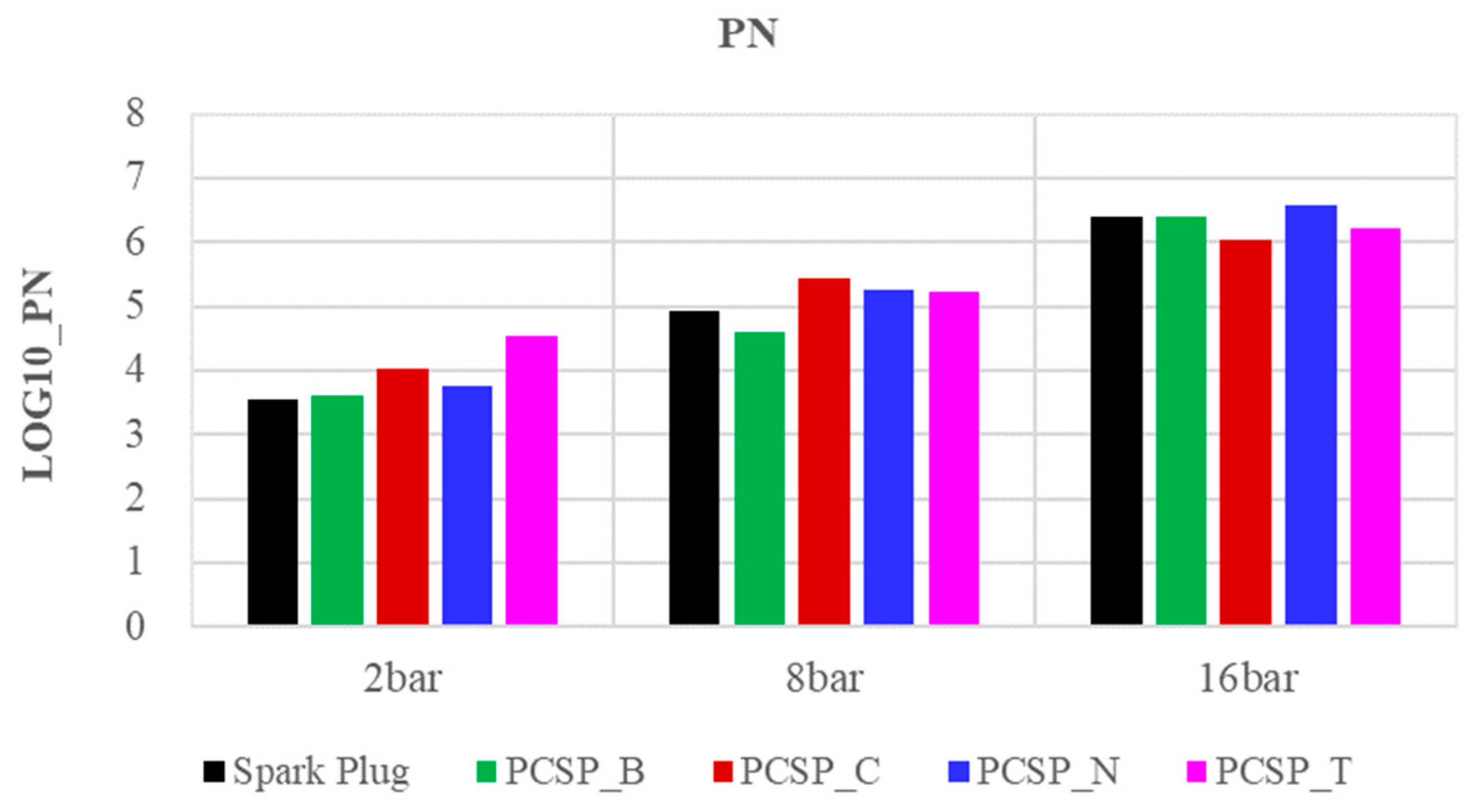
Figure 20 shows the PN emission characteristics for different pre-chamber structures, from which the following conclusions can be drawn.
(1)
PN emissions are positively correlated with load and increase with load.
(2)
PN emissions from the pre-chambers are overall comparable to those of conventional spark plugs.
(3)
PN emissions of pre-chambers with different structures are similar.
PN emission is closely related to fuel atomization. In this study, the direct-injection spray pressure was always maintained at 35 MPa, so the spray effect is relatively uniform and the PN emissions of various spark plugs are similar. In addition, as the load rises, the amount of cyclic fuel injection increases, resulting in a tendency for PN emissions to increase with the load.

4. Conclusions

In this paper, experiments were carried out on a turbo-charged direct-injection mass-production engine based on different pre-chamber structures. The different pre-chamber spark plugs used have significant differences in ground electrodes, electrode gaps, pre-chamber volume, and the number and diameter of jet holes. The study conditions included all loads in steps of 2 bar at 2000 r/min and characteristic loads at different speeds, including 3000 r/min, 3200 r/min, and 3600 r/min. The BMEP was kept stable during the experiments under each working condition, and data related to dynamics, economy, and emission were collected and analyzed. Based on the definition of GDI engine and pre-chamber spark plugs and test setting in this paper, the main conclusions of this paper are as follows.
(1)
The pre-chamber structure has a direct impact on engine performance, and there is a clear load demarcation line for the impact. Under the WOT condition, the dynamics of pre-chamber ignition are 1.6% higher than that of conventional spark plugs. At the small load of 2 bar, the economy of pre-chamber ignition is degraded by 6%; at the medium load of 8 bar, the two have comparable economy; and at the large load of 16 bar, pre-chamber ignition has favorable economy.
(2)
The pattern of the spark angle of pre-chamber jet ignition is similar to that of conventional spark plugs; namely, the spark angle decreases with the increase in load at the same rotational speed. By analyzing the MAP diagrams of spark angle, it is derived that the spark angle of pre-chamber spark plugs can be advanced by 2~3 °CA relative to conventional spark plugs.
(3)
The pre-chamber needs to be designed with separate ground electrodes to improve ignition reliability. On this basis, the integration of the pre-chamber with the main combustion chamber should be taken into account, especially utilizing the flow field of the main combustion chamber to improve the sweeping of gas in the pre-chamber and to improve the fuel economy and emissions of pre-chamber ignition.
(4)
The pre-chamber technology can meet the power requirements of the engine, and the emission level at each load is comparable to that of conventional spark plugs. From the point of view of technology application, pre-chamber ignition technology has potential application prospects.
The breakthroughs for future research lie in the following directions.
(1)
Fuel economy improvement for small load conditions represented by 2 bar.
(2)
The influence of the pre-chamber structure on combustion characteristics; investigation with CFD simulation on the influence of the pre-chamber structure on the in-cylinder flow field, mixture distribution, jet flame spread, and combustion process.
(3)
Further study on active pre-chamber to improve poor ignition ability during ultra-lean combustion, especially at low BMEP.

Author Contributions

Software, C.Y.; Resources, X.Z., Y.S. and C.Y.; Writing—original draft, X.Z.; Supervision, Y.S. and Z.Z.; Project administration, Y.S.; Funding acquisition, Z.Z. All authors have read and agreed to the published version of the manuscript.

Funding

This research was funded by [Shanghai Science and Technology Plan Project] grant number [21010503000]. And The APC was funded by [21010503000]. And The APC was funded by [21010503000].

Data Availability Statement

Data are contained within the article.

Conflicts of Interest

The authors declare no conflict of interest.

Definitions/Abbreviations

ACActive Chamber
APSAcceleration Pedal Position
BMEPBrake Mean Effective Pressure
BSFCBrake-Specific Fuel Consumption
°CACrank Angle Degree
CFDComputational Fluid Dynamics
COCarbon monoxide
CO2Carbon dioxide
COVCoefficient of Variation
CRCompression Ratio
EGRExhaust Gas Recirculation
GDIGasoline Direct Injection
HCHydrocarbons
KBLKnock Boundary Limit
λAir–Excess ratio
MBTMinimum Advance for Best Torque
NOxNitrogen Oxides
PCPassive Chamber
PCSPPre-Chamber Spark Plug
PNParticulate Number
RCEMRapid Compression Expansion Machine
VEVolumetric Efficiency
TexhTemperature for Exhaust port
TJITurbulent Jet Ignition
TKETurbulence Kinetic Energy
TPSThrottle Position Sensor
VVTintVariable Valve Timing for Intake
VVTexhVariable Valve Timing for Exhaust
WOTWide Open Throttle

References

  1. Ayala, F.; Heywood, J. Lean SI Engines: The Role of Combustion Variability in Defining Lean Limits; SAE Tech Paper, 2007-24-0030; SAE International: Warrendale, PA, USA, 2017. [Google Scholar]
  2. Salvi, B.L.; Subramanian, K.A. Experimental investigation and phenomenological model development of flame kernel growth rate in a gasoline fueled spark ignition engine. Appl. Energy 2015, 139, 93–103. [Google Scholar] [CrossRef]
  3. Pires, M.A.M.; Roso, V.R.; Alvarez, C.E.C.; Duarte, V.F.; Santos, N.D.S.A.; Valle, R.M. Effects of Operation Temperature on Exhaust Emissions in a Spark Ignition System Using Pre-Chamber Stratified System; SAE Technical Paper, 2019-36-0130; SAE International: Warrendale, PA, USA, 2019. [Google Scholar]
  4. Santos, N.D.S.A.; Alvarez, C.E.C.; Roso, V.R.; Baeta, J.G.C.; Valle, R.M. Combustion analysis of a SI engine with stratified and homogeneous pre-chamber ignition system using ethanol and hydrogen. Appl. Therm. Eng. 2019, 160, 113985. [Google Scholar] [CrossRef]
  5. Toulson, E.; Schock, H.; Attard, W. A Review of Pre-Chamber Initiated Jet Ignition Combustion Systems; SAE Technical Paper 2010-01-2263; SAE International: Warrendale, PA, USA, 2010. [Google Scholar]
  6. Badawy, T.; Bao, X.C.; Xu, H. Impact of spark plug gap on flame kernel propagation and engine performance. Appl. Energy 2017, 191, 311–327. [Google Scholar] [CrossRef]
  7. Turkish, M.C. 3-Valve Stratified Charge Engines: Evolvement, Analysis and Progression; SAE Technical Paper 741163; SAE International: Warrendale, PA, USA, 1974. [Google Scholar]
  8. Sandoval, M.H.B.; Alvarez, C.E.C.; Roso, V.R.; Santos, N.D.S.A.; Valle, R.M. The influence of volume variation in a homogeneous pre-chamber ignition system in combustion characteristics and exhaust emissions. J. Braz. Soc. Mech. Sci. Eng. 2020, 42, 72. [Google Scholar] [CrossRef]
  9. Noguchi, N.; Sanda, S.; Nakamura, N. Development of Toyota Lean Burn Engine; SAE Technical Paper 760757; SAE International: Warrendale, PA, USA, 1976. [Google Scholar]
  10. Adams, T.G. Torch Ignition for Combustion Control of Lean Mixtures; SAE Technical Paper 790440; SAE International: Warrendale, PA, USA, 1979. [Google Scholar]
  11. Brandstetter, W. The Volkswagen Lean Burn Pc-Engine Concept; SAE Technical Paper 800456; SAE International: Warrendale, PA, USA, 1980. [Google Scholar]
  12. Date, T.; Yagi, S. Research and Development of Honda CVCC Engine; SAE Technical Paper 740605; SAE International: Warrendale, PA, USA, 1974. [Google Scholar]
  13. Alvarez, C.E.; Couto, V.R.; Roso, A.B.; Thiriet; Valle, R.M. A review of pre-chamber ignition systems as lean combustion technology for SI engines. Appl. Therm. Eng. 2018, 128, 107–120. [Google Scholar]
  14. Yamaguchi, S.; Ohiwa, N.; Hasegawa, T. Ignition and burning process in a divided chamber bomb. Combust. Flame 1985, 59, 177–187. [Google Scholar] [CrossRef]
  15. Yasuhiro, U.; Takashi, K.; Toru, T. Combustion Technologies for Latest Automobile Engines and the Future Directions. J. Combust. Soc. Jpn. 2018, 60, 18–26. [Google Scholar]
  16. Attard, W.; Fraser, N.; Parsons, P.; Toulson, E. A Turbulent Jet Ignition Pre-Chamber Combustion System for Large Fuel Economy Improvements in a Modern Vehicle Powertrain; SAE Technical Paper 2010-01-1457; SAE International: Warrendale, PA, USA, 2010. [Google Scholar]
  17. Attard, W.; Bassett, M.; Parsons, P.; Blaxill, H. A New Combustion System Achieving High Drive Cycle Fuel Economy Improvements in a Modern; SAE Technical Paper 2011-01-0664; SAE International: Warrendale, PA, USA, 2011. [Google Scholar]
  18. Attard, W.; Bassett, M.; Parsons, P.; Blaxill, H. A Lean Burn Gasoline Fueled Pre-Chamber Jet Ignition Combustion System Achieving High Efficiency and Low NOx at Part Load; SAE Technical Paper 2012-01-1146; SAE International: Warrendale, PA, USA, 2012. [Google Scholar]
  19. Bunce, M.; Blaxill, H.; Kulatilaka, W.; Jiang, N. The Effects of Turbulent Jet Characteristics on Engine Performance Using a Pre-Chamber Combustor; SAE Technical Paper 201401-1195; SAE International: Warrendale, PA, USA, 2014. [Google Scholar]
  20. Chinnathambi, P.; Bunce, M.; Cruff, L. RANS Based Multidimensional Modeling of an Ultra-Lean Burn Pre-Chamber Combustion System with Auxiliary Liquid Gasoline Injection; SAE Technical Paper 2015-010386; SAE International: Warrendale, PA, USA, 2014. [Google Scholar]
  21. Sens, M.; Binder, E.; Benz, A.; Kramer, L.; Schultalbers, M.; Blumenröde, K. Pre-chamber Ignition as a Key Technology for Highly Efficient SI Engines New Approaches and Operating Strategies. In Proceedings of the 39th International Vienna Motor Symposium, Vienna, Austria, 26–27 April 2018. [Google Scholar]
  22. Sens, M.; Binder, E. Pre-chamber Ignition as a Key Technology for Future Powertrain Fleets. MTZ Worldw. 2019, 80, 44–45. [Google Scholar] [CrossRef]
  23. Attard, W.P.; Parsons, P. Flame Kernel Development inside a Pre-Chamber of a Turbulent jet Ignition Combustion System in a Modern Vehicle Powertrain; SAE Tech Paper, 2010-01-2260; SAE International: Warrendale, PA, USA, 2010. [Google Scholar]
  24. Millo, F.; Rolando, L.; Piano, A.; Sementa, P.; Catapano, F.; Di Iorio, S.; Bianco, A. Experimental and Numerical Investigation of a Passive Pre-Chamber Jet Ignition Single-Cylinder Engine; SAE Technical Paper 2021-24-0010; SAE International: Warrendale, PA, USA, 2021. [Google Scholar]
  25. Frasci, E.; Sementa, P.; Arsie, I.; Jannelli, E.; Vaglieco, B.M. Experimental and Numerical Investigation of a Lean SI Engine to Be Operated as Range Extender for Hybrid Powertrains; SAE Technical Paper 2021-24-0005; SAE International: Warrendale, PA, USA, 2021. [Google Scholar]
  26. Marquez, M.E.; Hlaing, P.; Houidi, M.B.; Magnotti, G.; Johansson, B.; Cenker, E. Optical Diagnostics of Pre-Chamber Combustion with Flat and Bowl-In Piston Combustion Chamber. Combustion Chamber; SAE Technical Paper 2021-01-0528; SAE International: Warrendale, PA, USA, 2021. [Google Scholar]
  27. Yu, X.; Zhang, A.; Baur, A.; Engineer, N. The Impact of Pre-Chamber Design on Part Load Efficiency and the Impact of Pre-Chamber Design on Part Load Efficiency and Emissions of a Miller Cycle Light Duty Gasoline Engine; SAE Technical Paper 2021-01-0479; SAE International: Warrendale, PA, USA, 2021. [Google Scholar]
Figure 1. Comparison of (a) passive pre-chamber and (b) active pre-chamber structure.
Energies 17 01773 g001
Figure 2. Appearance characteristics of experimental spark plugs.
Energies 17 01773 g002
Figure 3. Firing section configuration of experimental spark plugs.
Energies 17 01773 g003
Figure 4. Electrode design of experimental spark plugs.
Energies 17 01773 g004
Figure 5. Schematic diagram of the assembly of spark plugs on cylinder head.
Energies 17 01773 g005
Figure 6. Pre-chamber spark ignition engine test bench.
Energies 17 01773 g006
Figure 7. Installation of pre-chamber spark plug C.
Energies 17 01773 g007
Figure 8. WOT characteristics of the engine at 2000 r/min.
Energies 17 01773 g008
Figure 9. WOT characteristics of the engine at 3600 r/min.
Energies 17 01773 g009
Figure 10. Economy of 2000 r/min and 2 bar engine.
Energies 17 01773 g010
Figure 11. Engine economy of 2000 r/min and 8 bar.
Energies 17 01773 g011
Figure 12. Engine economy of 2000 r/min and 16 bar.
Energies 17 01773 g012
Figure 13. MAP diagram of spark angle for conventional spark plug.
Energies 17 01773 g013
Figure 14. MAP diagram of spark angle for pre-chamber spark plugs.
Energies 17 01773 g014
Figure 15. MAP diagram of specific fuel consumption for conventional spark plug.
Energies 17 01773 g015
Figure 16. MAP diagram of specific fuel consumption of pre-chamber spark plugs.
Energies 17 01773 g016
Figure 17. THC emission characteristics.
Energies 17 01773 g017
Figure 18. CO emission characteristics.
Energies 17 01773 g018
Figure 19. NOx emission characteristics.
Energies 17 01773 g019
Figure 20. PN emission characteristics.
Energies 17 01773 g020
Table 1. Characteristic parameters of the experimental engine.
ParameterParameter Value
Spark Ignition typeConventional Spark Plug and Pre-chamber Spark Plug
Engine displacement0.996 L
Bore diameter72.6 mm
Stroke80.2 mm
Connecting rod length141.9 mm
Stroke bore ratio1.10
Number of valves per cylinder4
Compression Ratio (CR)10.5
Intake methodexhaust gas turbo-charged
Injecting methodGasoline Direct Injection (GDI)
Maximum injection pressure350 bar
EGR systemWater-cooled EGR
Rated power85 kW
Rated torque175 Nm
Table 2. Structural characteristics of spark plugs.
Design FeatureGround
Electrode
GapPre-Chamber
Volume
NumberDiameter
Spark PlugJ-type0.75 mm---
PCSP_Aindependent
electrode × 2
0.3 mm376 mm341.0 mm
PCSP_Bindependent
electrode × 2
0.65 mm618 mm341.2 mm
PCSP_Cindependent
electrode × 1
0.7 mm558 mm34one is 1.75 mm,
others are 1.5 mm
PCSP_DPre-chamber inner surface0.45 mm280 mm361.2 mm
Table 3. Experimental measurement equipment and specification.
Measuring DeviceEquipment Specification
DynamometerAC asynchronous dynamometer 202/12
Measurement and control systemPUMA (error: 0.3%)
Fuel consumption meterAVL740 (error: 0.3%)
Oil/Cooling TrolleyAVL577 (error: 3 °C)
Emissions AnalyzerMEXA-ONED2EGR
PN AnalyzerMEXA-2100SPCS
Disclaimer/Publisher’s Note: The statements, opinions and data contained in all publications are solely those of the individual author(s) and contributor(s) and not of MDPI and/or the editor(s). MDPI and/or the editor(s) disclaim responsibility for any injury to people or property resulting from any ideas, methods, instructions or products referred to in the content.

