
Enhancing Electric Vehicle Charger Performance with Synchronous Boost and Model Predictive Control for Vehicle-to-Grid Integration


Abstract
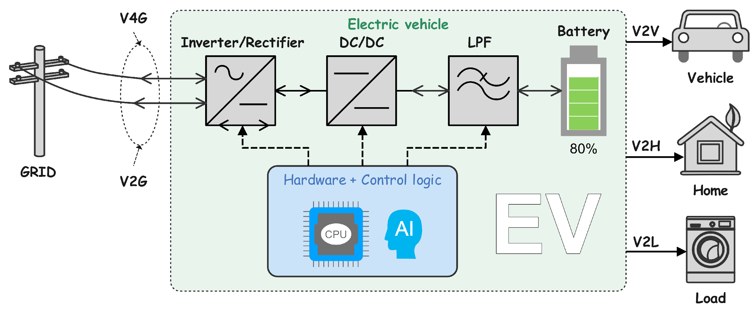
1. Introduction
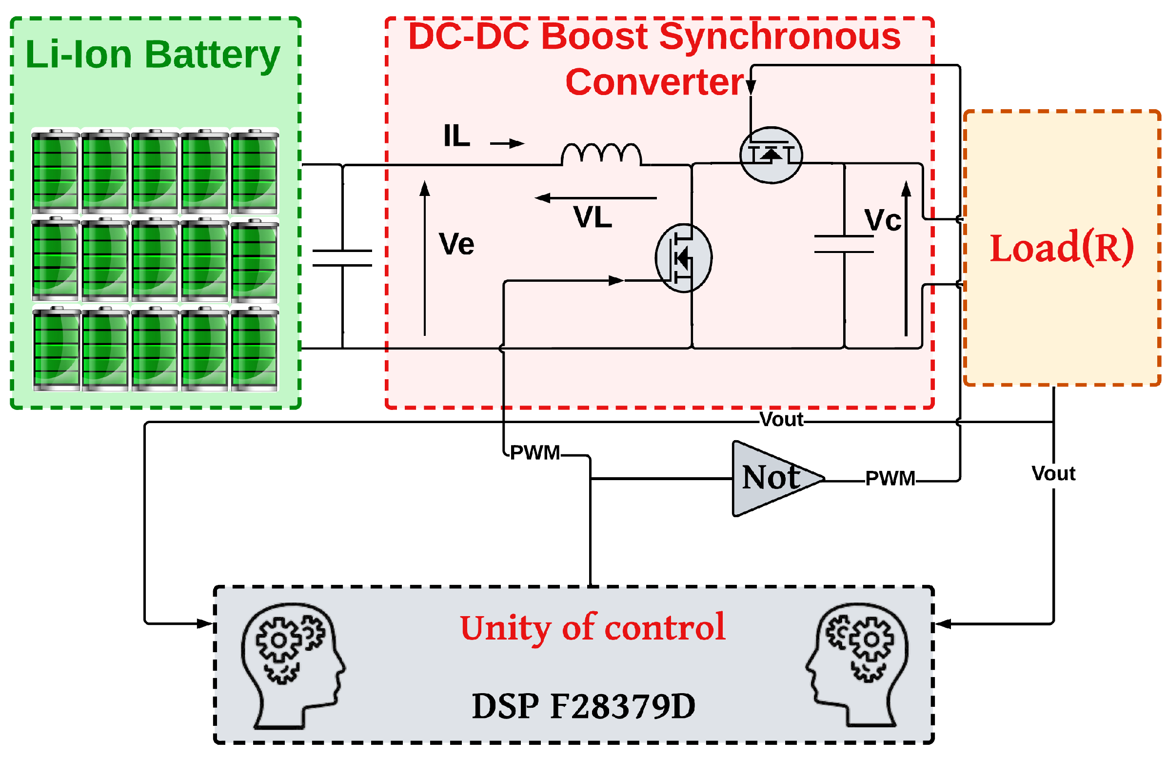
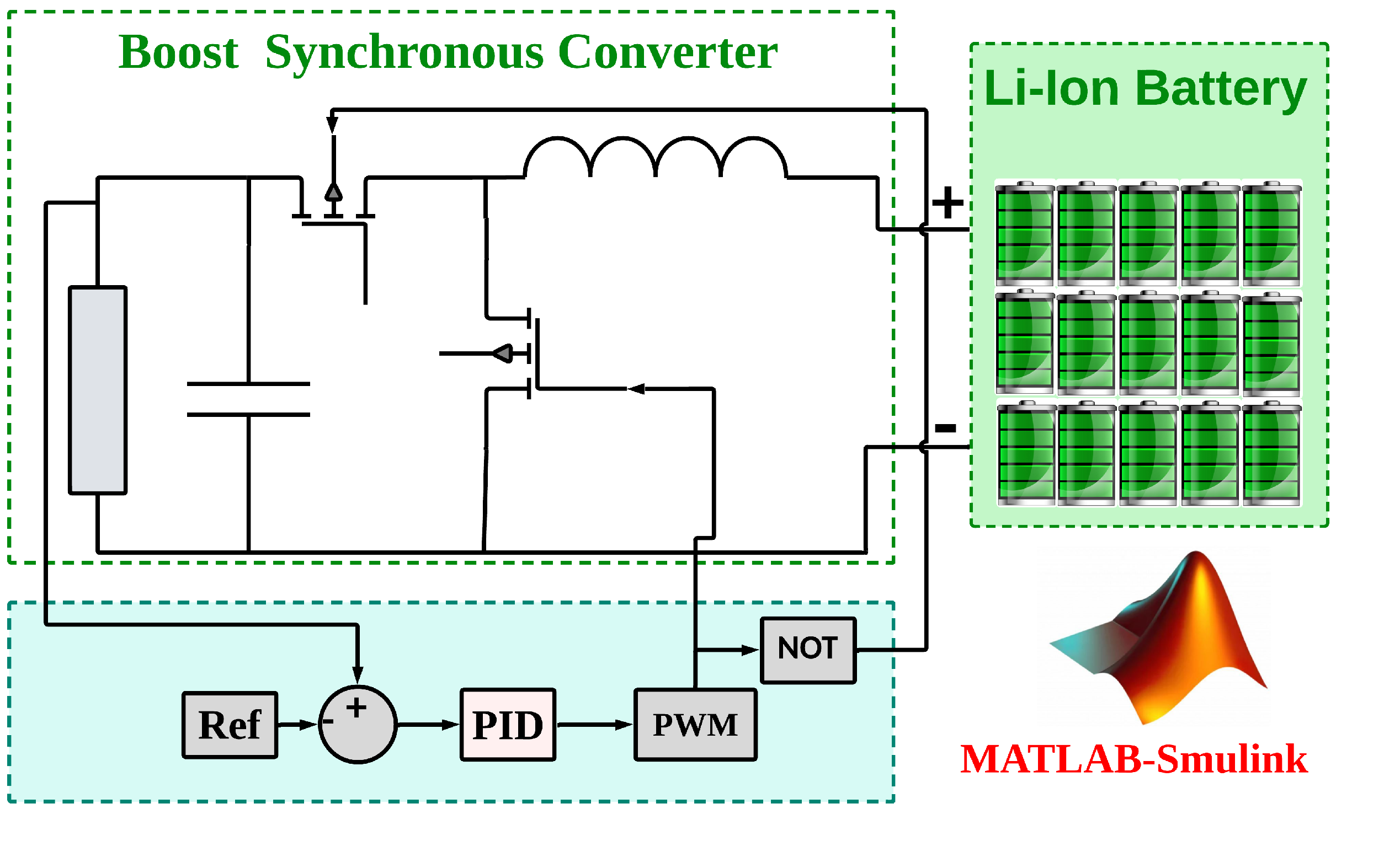
2. DC-DC Boost Converter
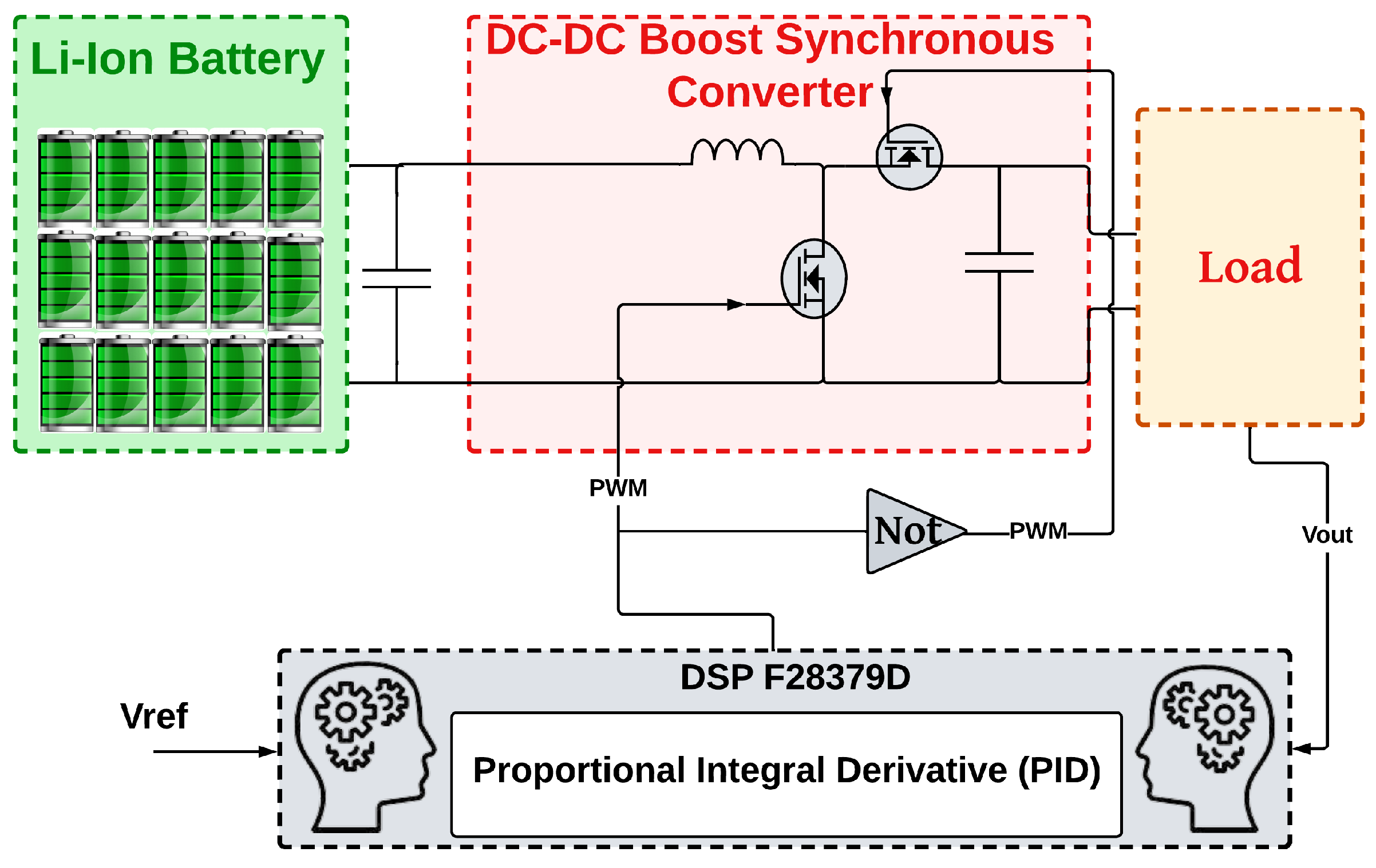
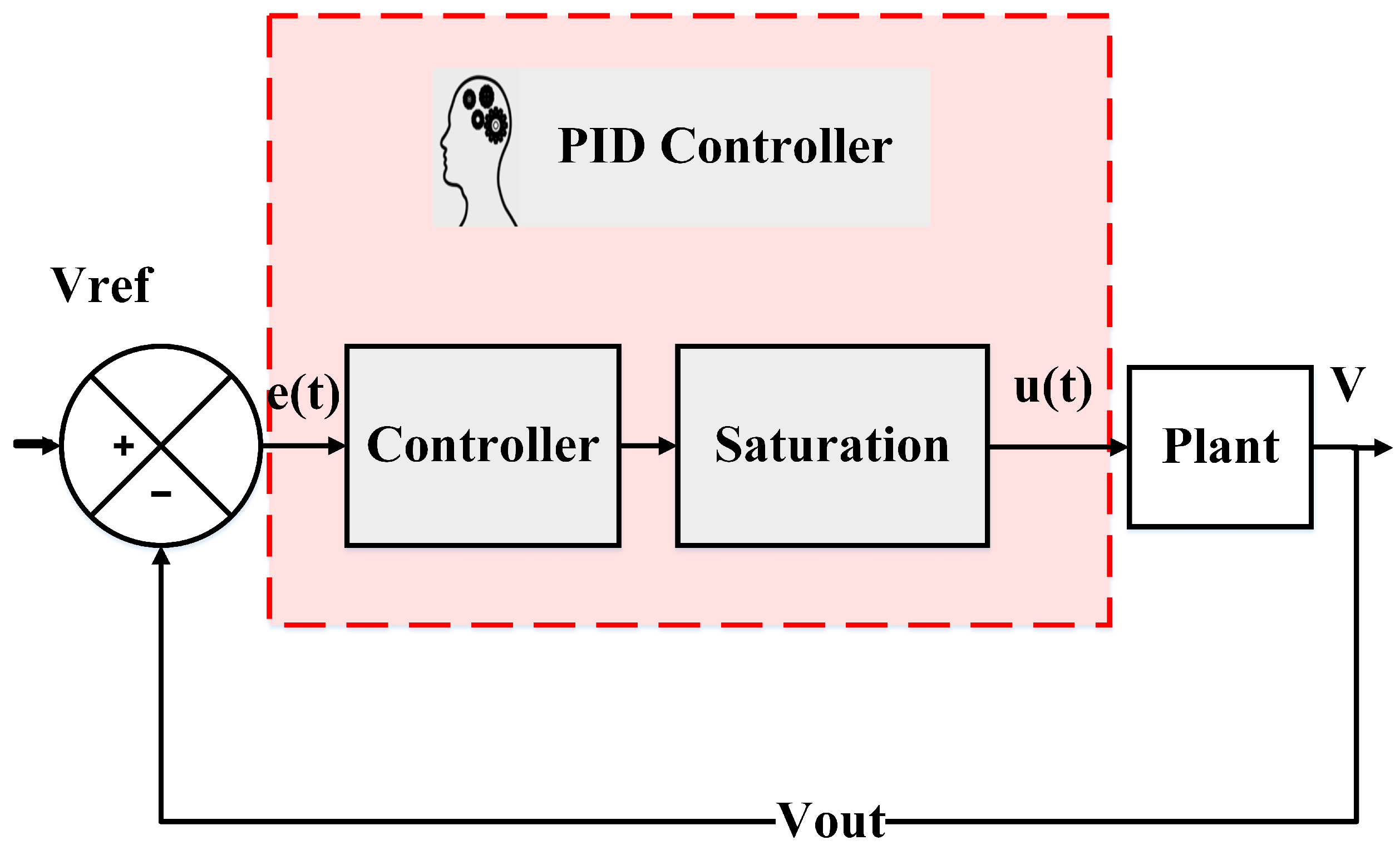
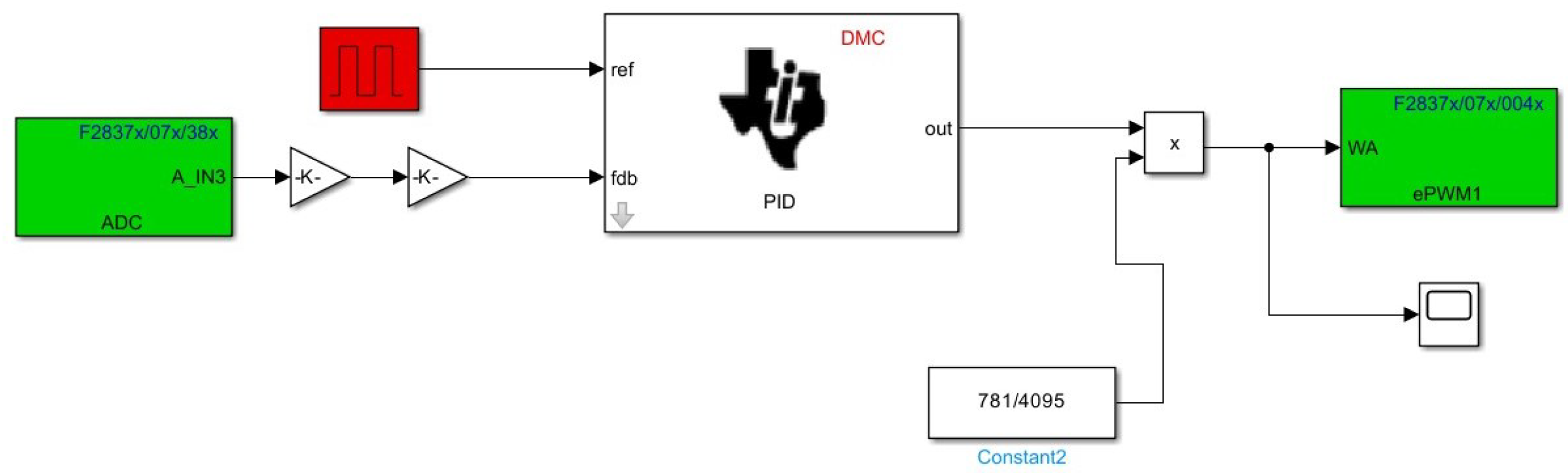
3. PID Controller
- (1)
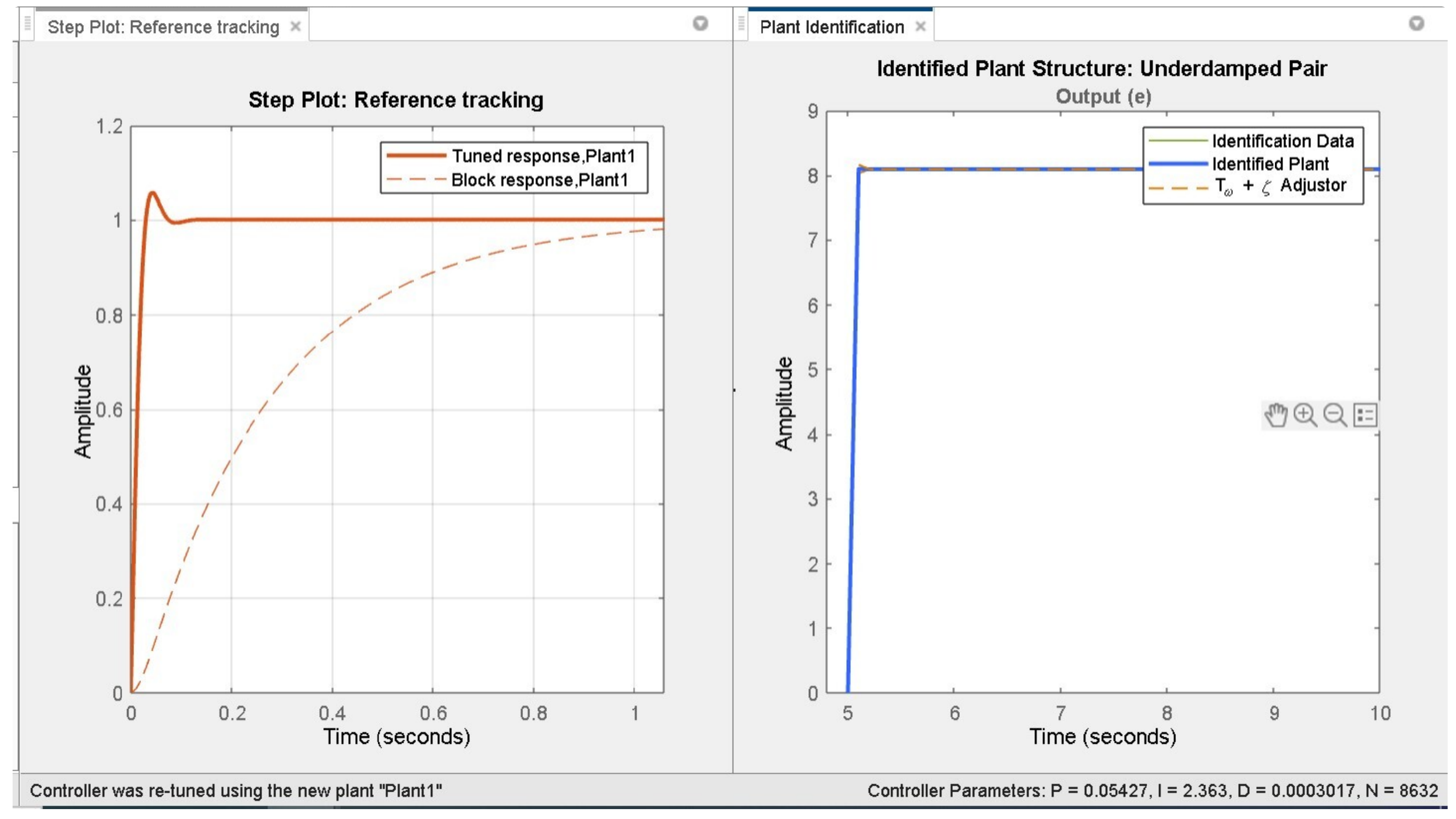
- Initiating the PID tuner, which automatically derives a linear plant model from the Simulink model and crafts an initial controller design.
- (2)
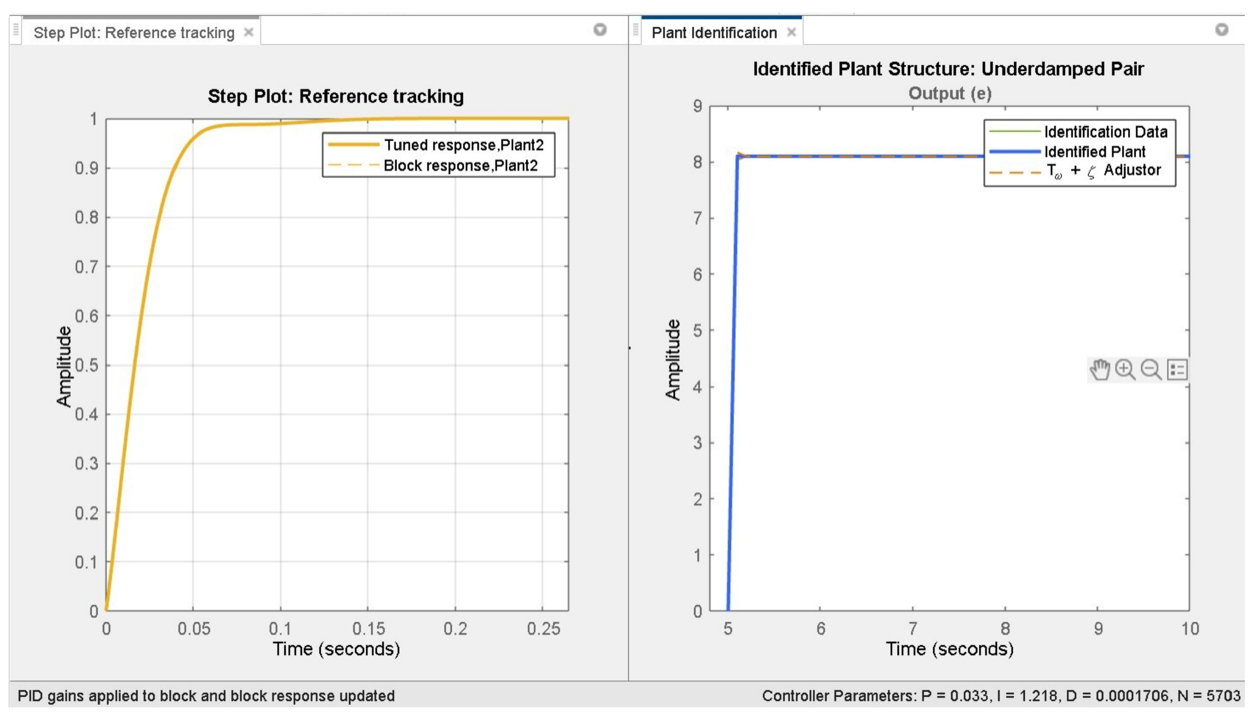
- Adjusting the controller within the PID tuner by modifying design parameters across two design modes. The tuner then calculates PID settings that effectively stabilize the system.
- (3)
- Transferring the tuned controller parameters to the PID controller block and evaluating the controller’s performance within Simulink.
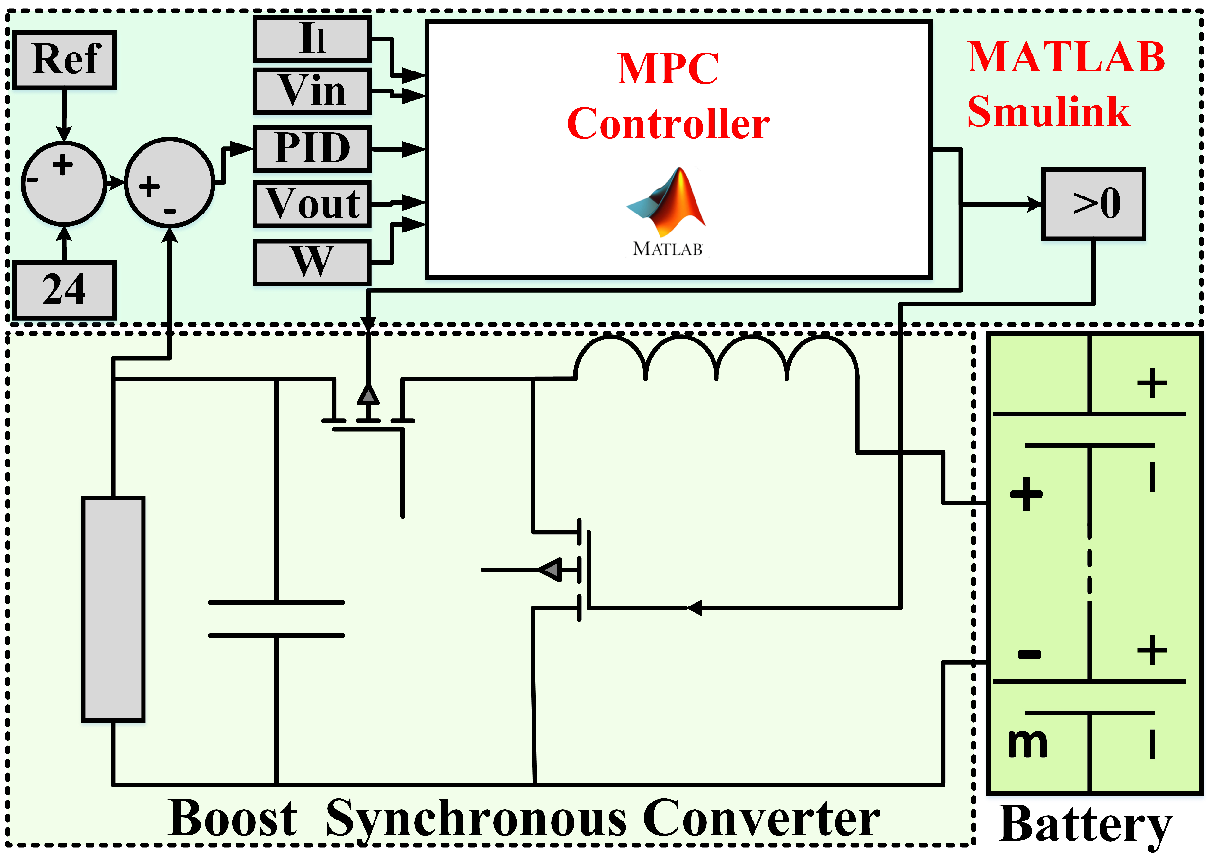
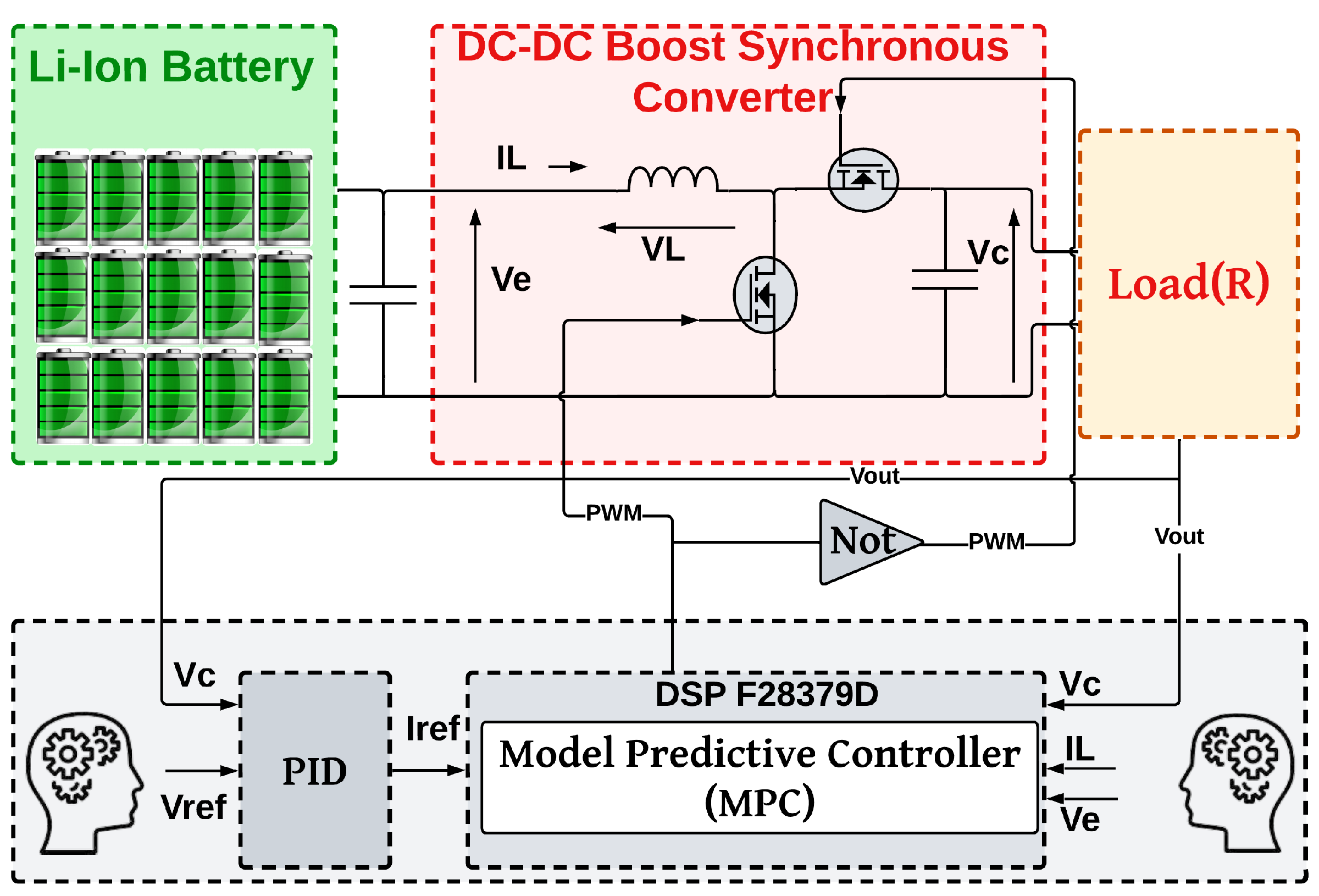
4. Model Predictive Controller (MPC)
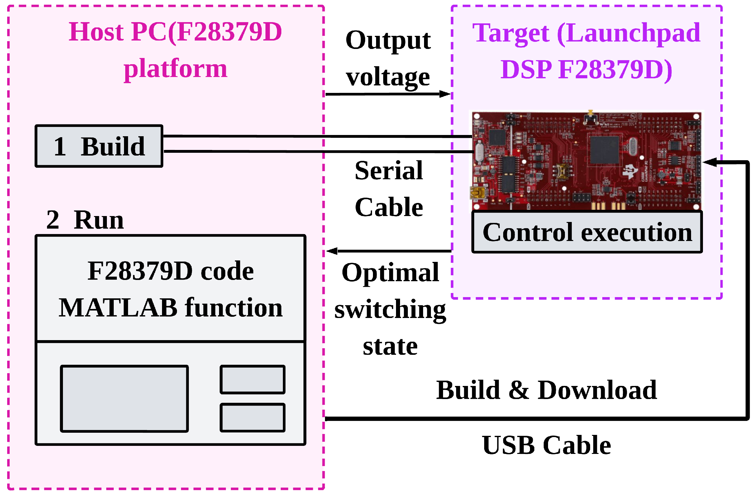
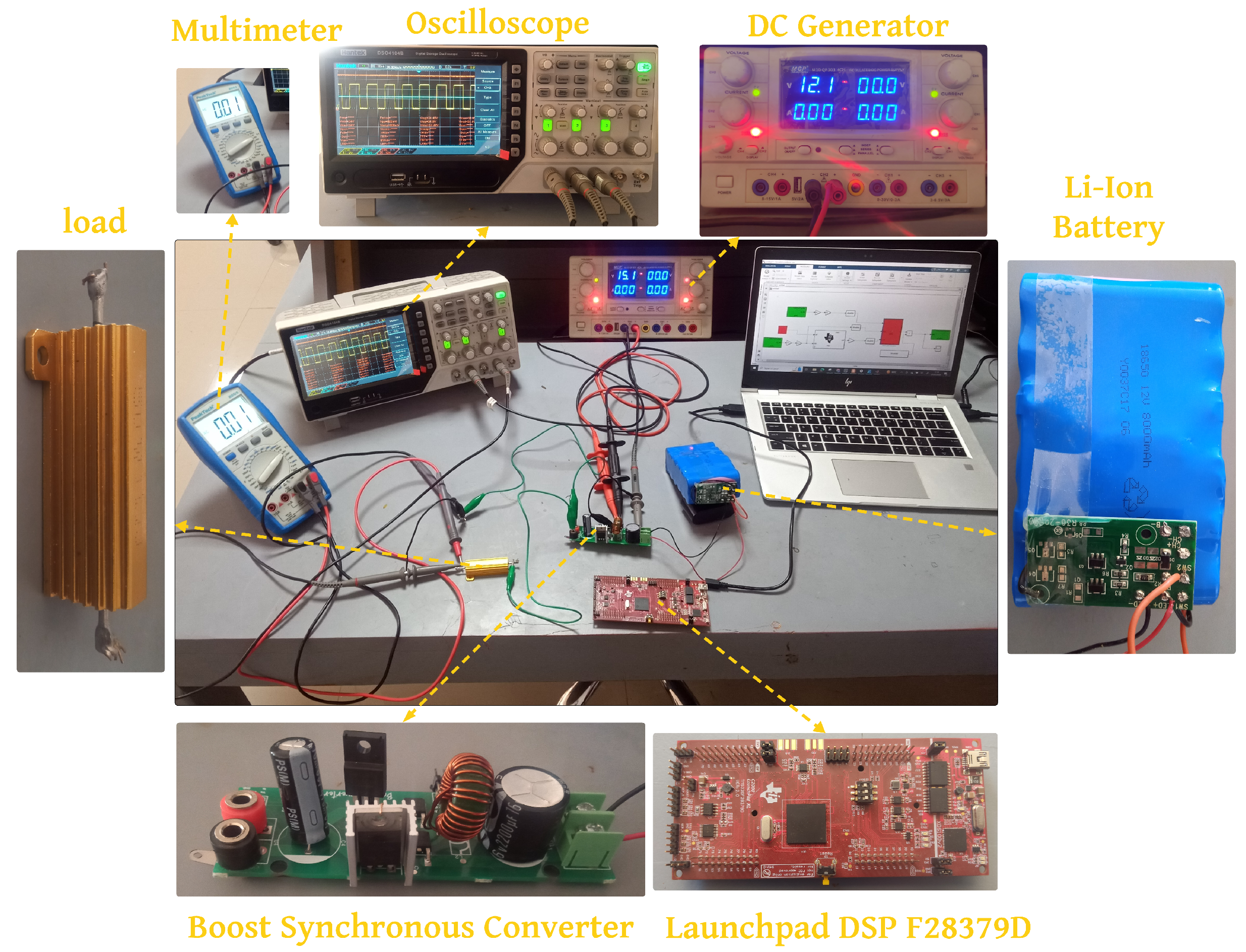
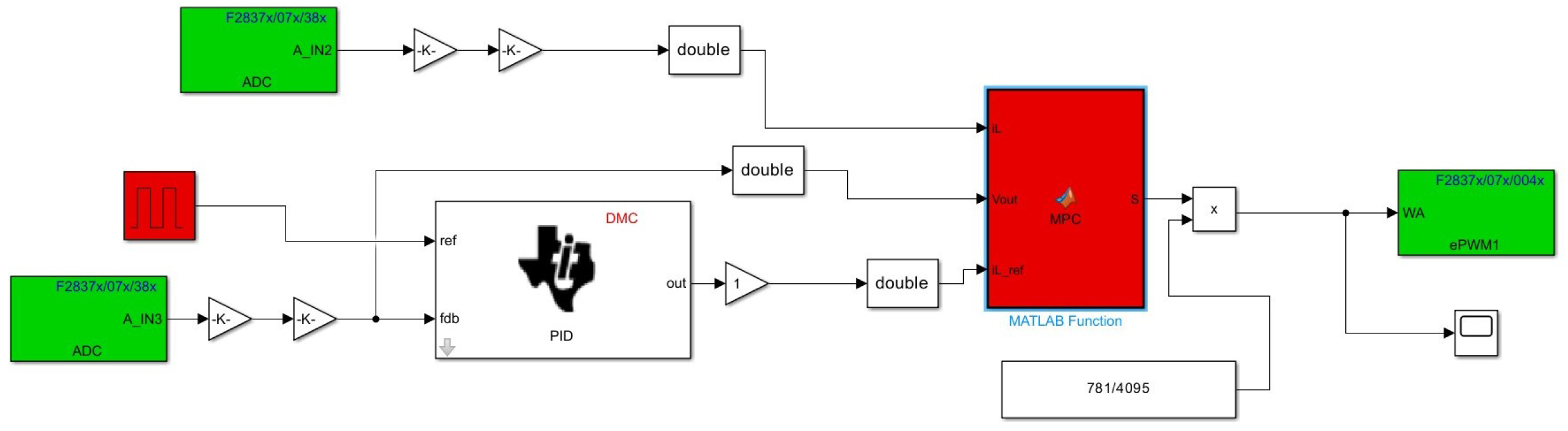
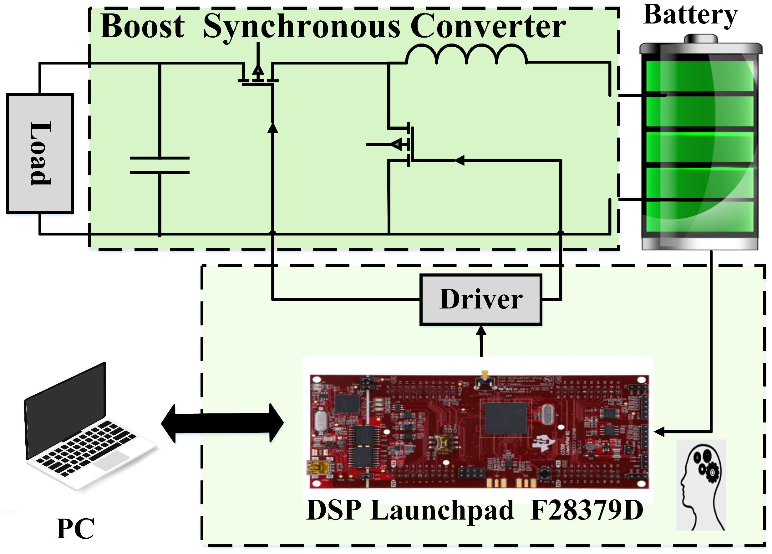
5. Hardware in the Loop
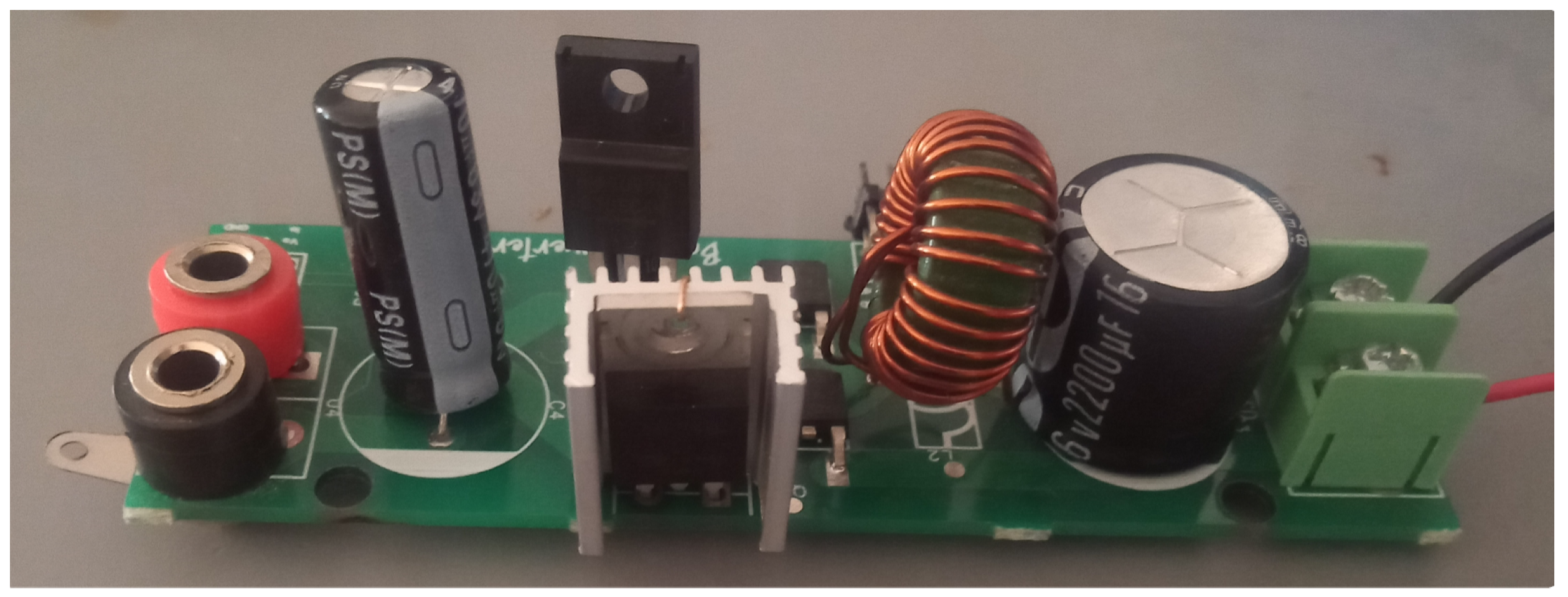
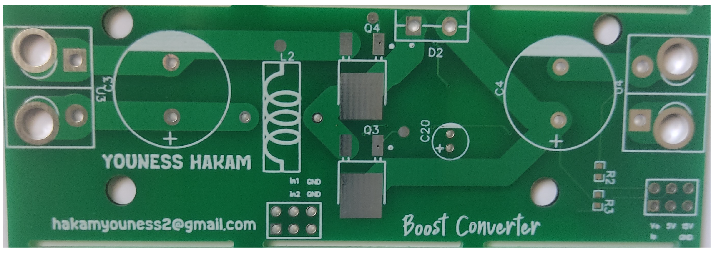
6. Implementation of DC-DC
7. Results and Discussion
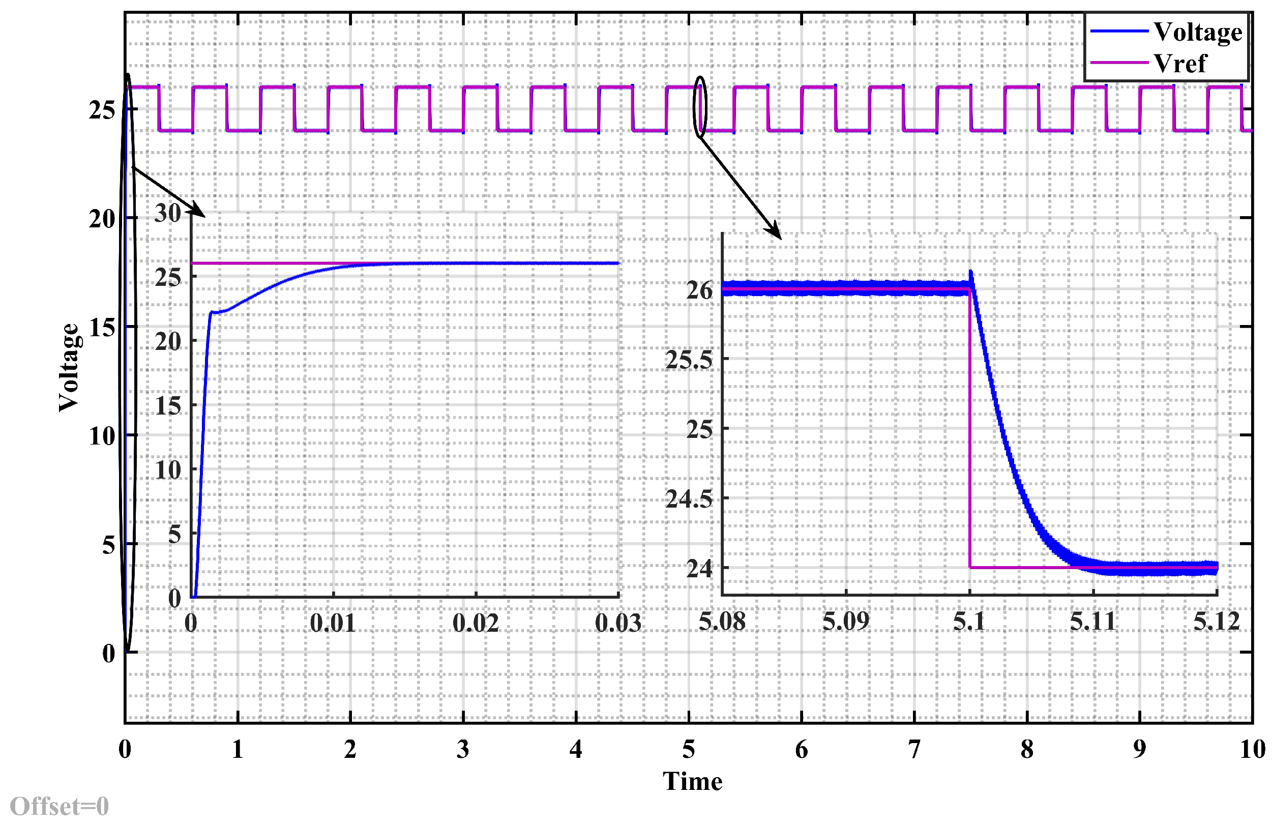
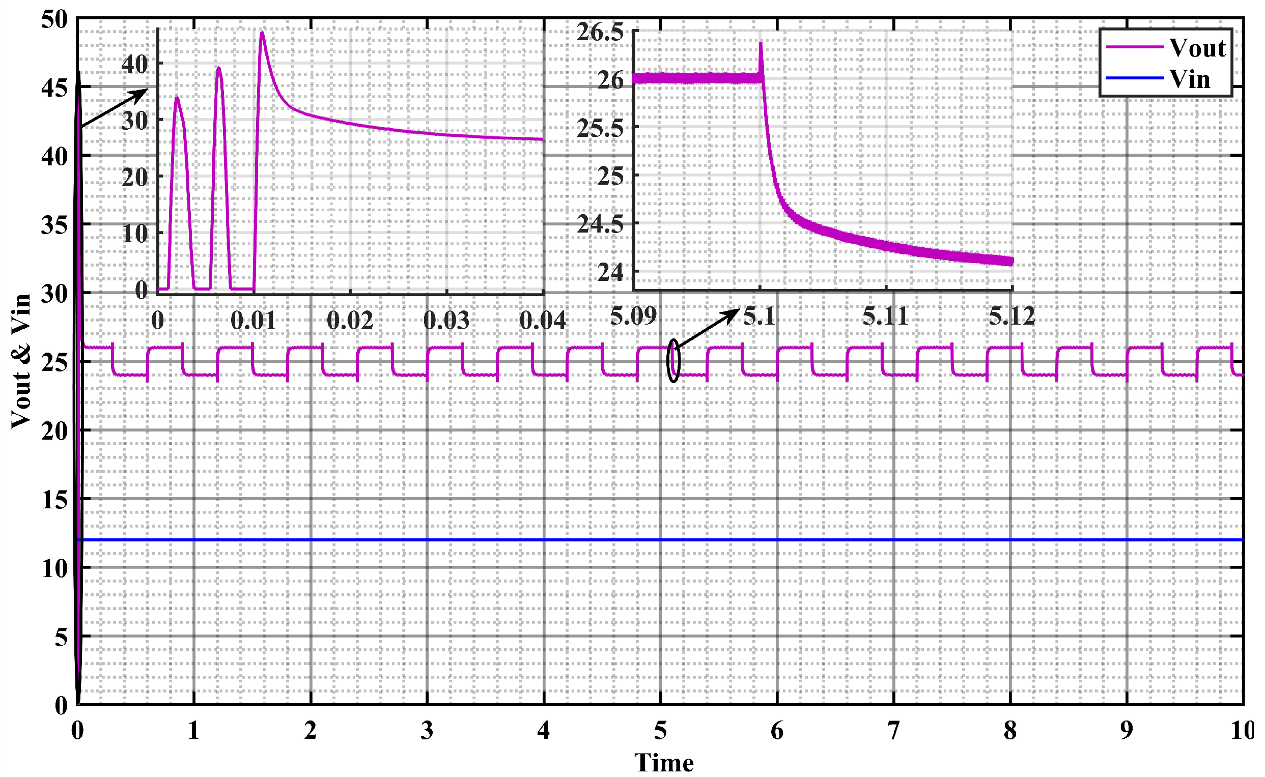
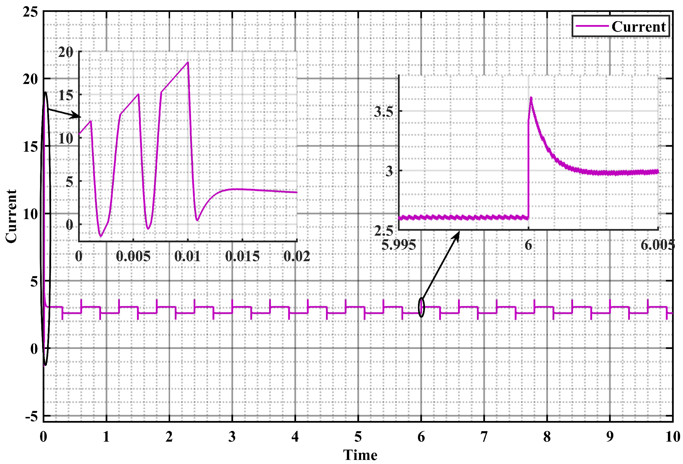
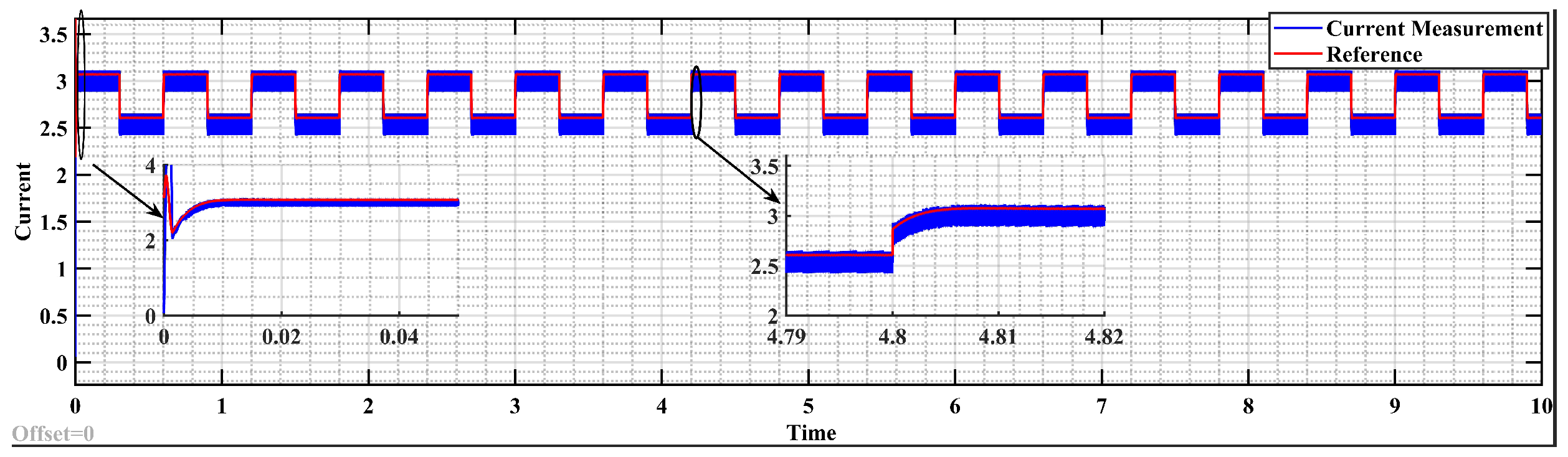
7.1. Results of Simulation
7.2. Experimental Results
8. Conclusions
- Model predictive control (MPC) addresses challenges in DC-DC boost converters by considering system dynamics and constraints in real time.
- Experimental validation of synchronous boost converters and MPC involves hardware-in-the-loop simulations, benchtop testing, and field trials.
- Transitioning from diodes to MOSFETs in boost converters enhances efficiency by minimizing conduction losses, but may introduce challenges like increased switching losses.
- The TMS320F28379D digital signal processor enables real-time control of boost converters with high PWM frequencies and precise sensor readings.
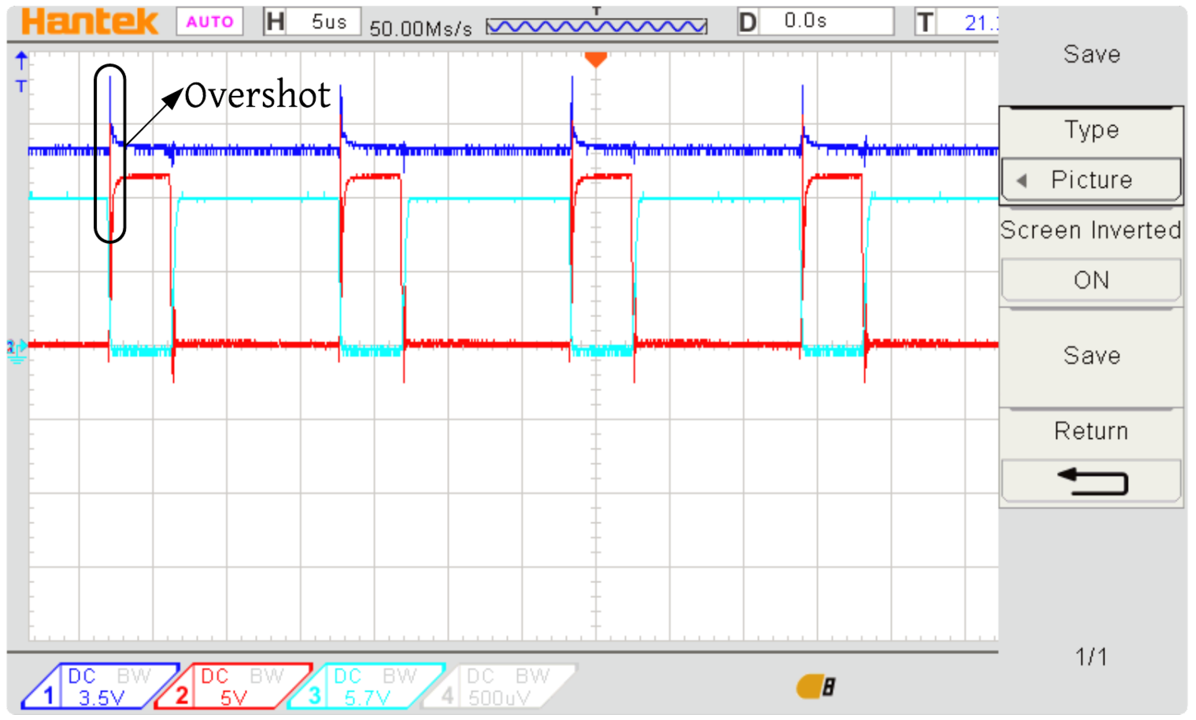
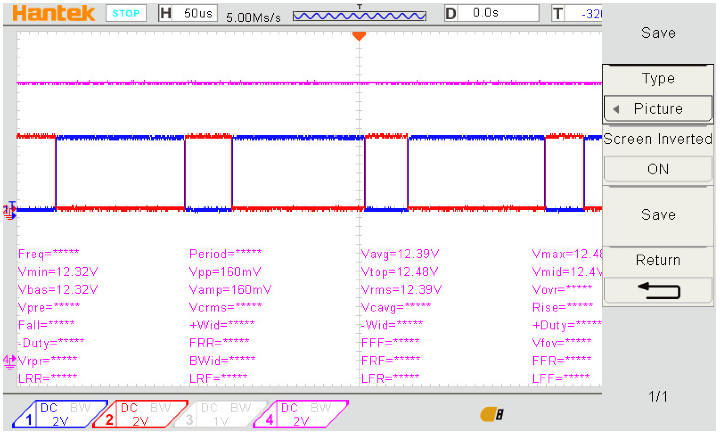
- MPC outperforms PID control in simulation and experimental settings by providing improved transient response, reduced overshoot by , and enhanced disturbance rejection.
- Boost converter simulation parameters are determined based on component datasheets and system requirements, with validation against real-world measurements.
- The overshot in output voltage with PID control may result from inherent limitations like integral windup and slow response, which MPC effectively mitigates.
Author Contributions
Funding
Data Availability Statement
Conflicts of Interest
References
- Jaman, S.; Chakraborty, S.; Tran, D.-D.; Geury, T.; El Baghdadi, M.; Hegazy, O. Review on Integrated On-Board ChargerTraction Systems: V2G Topologies, Control Approaches, Standards and Power Density State-of-the-Art for Electric Vehicle. Energies 2022, 15, 5376. [Google Scholar] [CrossRef]
- Rathore, A.K.; Prasanna, U.R. Comparison of soft-switching voltage-fed and current-fed bi-directional isolated dc/dc converters for fuel cell vehicles. In Proceedings of the2012 IEEE International Symposium on Industrial Electronics, Hangzhou, China, 28–31 May 2012; pp. 252–257. [Google Scholar]
- Yazdani, A.; Iravani, R. Voltage-Sourced Converters in Power Systems: Modeling, Control, and Applications; Wiley-IEEE Press: New York, NY, USA, 2010. [Google Scholar]
- Longo, M.; Foiadelli, F.; Yaïci, W. Electric vehicles integrated with renewable energy sources for sustainable mobility. In New Trends in Electrical Vehicle Powertrains; Martinez, L.R., Ed.; IntechOpen: Winchester, UK, 2019. [Google Scholar]
- Pinto, J.G.; Monteiro, V.; Gonçalves, H.; Afonso, J.L. Onboard reconfigurable battery charger for electric vehicles with traction-to-auxiliary mode. IEEE Trans. Veh. Technol. 2014, 63, 1104–1116. [Google Scholar] [CrossRef]
- Karami, Z.; Shafiee, Q.; Sahoo, S.; Yaribeygi, M.; Bevrani, H.; Dragicevic, T. Hybrid Model Predictive Control of DC–DC Boost Converters With Constant Power Load. IEEE Trans. Energy Convers 2021, 36, 1347–1356. [Google Scholar] [CrossRef]
- Gu, B.; Dominic, J.; Lai, J.; Zhao, Z.; Liu, C. High Boost Ratio Hybrid Transformer DC– DC Converter for Photovoltaic Module Applications. IEEE Trans Power Electron 2013, 28, 2048–2058. [Google Scholar] [CrossRef]
- Dragičević, T.; Vazquez, S.; Wheeler, P. Advanced Control Methods for Power Converters in DG Systems and Microgrids. IEEE Trans. Ind. Electron. 2021, 68, 5847–5862. [Google Scholar] [CrossRef]
- Cheng, L.; Acuna, P.; Aguilera, R.P.; Jiang, J.; Wei, S.; Fletcher, J.E.; Lu, D.D.C. Model Predictive Control for DC–DC Boost Converters With Reduced-Prediction Horizon and Constant Switching Frequency. IEEE Trans. Power Electron. 2018, 33, 9064–9075. [Google Scholar] [CrossRef]
- Xu, Q.; Yan, Y.; Zhang, C.; Dragicevic, T.; Blaabjerg, F. An Offset-Free Composite Model Predictive Control Strategy for DC/DC Buck Converter Feeding Constant Power Loads. IEEE Trans. Power Electron. 2020, 35, 5331–5342. [Google Scholar] [CrossRef]
- Jia, Y.; Dong, Z.Y.; Sun, C.; Chen, G. Distributed Economic Model Predictive Control for a Wind–Photovoltaic–Battery Microgrid Power System. IEEE Trans. Sustain. Energy 2020, 11, 1089–1099. [Google Scholar] [CrossRef]
- Vazquez, S.; Rodriguez, J.; Rivera, M.; Franquelo, L.G.; Norambuena, M. Model Predictive Control for Power Converters and Drives:Advances and Trends. IEEE Trans. Ind. Electron. 2016, 64, 935–947. [Google Scholar] [CrossRef]
- Raviraj, V.S.C.; Sen, P.C. Comparative study of proportional-integral, sliding mode, and fuzzy logic controllers for power converters. IEEE Trans. Ind. Appl. 1997, 33, 518–524. [Google Scholar] [CrossRef]
- Meena, R. Simulation study of boost converter with various control techniques. Int. J. Sci. Res. (IJSR) 2014, 3, 74–79. [Google Scholar]
- Mitra, L.; Swain, N. Closed loop control of solar powered boost converter with PID controller. In Proceedings of the 2014 IEEE International Conference on Power Electronics, Drives and Energy Systems (PEDES), Mumbai, India, 16–19 December 2014. [Google Scholar]
- Verma, P.; Patel, N.; Nair, N.K.C.; Sikander, A. Design of PID controller using cuckoo search algorithm for buck-boost converter of LED driver circuit. In Proceedings of the 2016 IEEE 2nd Annual Southern Power Electronics Conference (SPEC), Auckland, New Zealand, 5–8 December 2016; pp. 1–4. [Google Scholar]
- Andrés-Martínez, O.; Flores-Tlacuahuac, A.; Ruiz-Martinez, O.F.; Mayo-Maldonado, J.C. Nonlinear Model Predictive Stabilization of DC–DC Boost Converters With Constant Power Loads. IEEE J. Emerg. Sel. Topics Power Electron. 2021, 9, 822–830. [Google Scholar] [CrossRef]
- Ayad, A.; Karamanakos, P.; Kennel, R. Direct Model Predictive Current Control Strategy of Quasi-Z-Source Inverters. IEEE Trans. Power Electron. 2017, 32, 5786–5801. [Google Scholar] [CrossRef]
- Villarroel, F.A.; Espinoza, J.R.; Pérez, M.A.; Ramírez, R.O.; Baier, C.R.; Sbárbaro, D.; Silva, J.J.; Reyes, M.A. Stable Shortest Horizon FCS-MPC Output Voltage Control in Non-Minimum Phase BoostType Converters Based on Input-State Linearization. IEEE Trans. Energy Convers. 2021, 36, 1378–1391. [Google Scholar] [CrossRef]


| Parameter | Value |
|---|---|
| 24 V | |
| Capacitor C | 47 µF |
| Inductor L | 2.5 mH |
| Sampling time | 34 µs |
| Parameters | Values |
|---|---|
| 0.334 | |
| 1.2 |
| Parameter | Value |
|---|---|
| 24 V | |
| Capacitor C | 470 µF |
| Inductor L | 5 mH |
| 50 KHz | |
| Input DC | 12 V |
| Sampling time | 34 µs |
| Technique | Response Time | Overshot |
|---|---|---|
| = 0.01 s | D = 0 V | |
| = 0.5 s | D = 3.45 V |
Disclaimer/Publisher’s Note: The statements, opinions and data contained in all publications are solely those of the individual author(s) and contributor(s) and not of MDPI and/or the editor(s). MDPI and/or the editor(s) disclaim responsibility for any injury to people or property resulting from any ideas, methods, instructions or products referred to in the content. |
© 2024 by the authors. Licensee MDPI, Basel, Switzerland. This article is an open access article distributed under the terms and conditions of the Creative Commons Attribution (CC BY) license (https://creativecommons.org/licenses/by/4.0/).
Share and Cite
Hakam, Y.; Gaga, A.; Tabaa, M.; El hadadi, B. Enhancing Electric Vehicle Charger Performance with Synchronous Boost and Model Predictive Control for Vehicle-to-Grid Integration. Energies 2024, 17, 1787. https://doi.org/10.3390/en17071787
Hakam Y, Gaga A, Tabaa M, El hadadi B. Enhancing Electric Vehicle Charger Performance with Synchronous Boost and Model Predictive Control for Vehicle-to-Grid Integration. Energies. 2024; 17(7):1787. https://doi.org/10.3390/en17071787
Chicago/Turabian StyleHakam, Youness, Ahmed Gaga, Mohamed Tabaa, and Benachir El hadadi. 2024. "Enhancing Electric Vehicle Charger Performance with Synchronous Boost and Model Predictive Control for Vehicle-to-Grid Integration" Energies 17, no. 7: 1787. https://doi.org/10.3390/en17071787
APA StyleHakam, Y., Gaga, A., Tabaa, M., & El hadadi, B. (2024). Enhancing Electric Vehicle Charger Performance with Synchronous Boost and Model Predictive Control for Vehicle-to-Grid Integration. Energies, 17(7), 1787. https://doi.org/10.3390/en17071787