Article

Multi-Objective Optimization of an Organic Rankine Cycle (ORC) for a Hybrid Solar–Waste Energy Plant

1
School of Marine Technology and Environment, Dalian Ocean University, Dalian 116023, China
2
Department of Basic, Dalian Naval Academy, Dalian 116013, China
*
Author to whom correspondence should be addressed.
Energies 2024, 17(8), 1810; https://doi.org/10.3390/en17081810
Submission received: 17 March 2024 / Revised: 30 March 2024 / Accepted: 9 April 2024 / Published: 10 April 2024
(This article belongs to the Special Issue Modeling Analysis and Optimization of Energy System)

Abstract

:
In pursuit of sustainable development and mitigation of the intermittency challenge associated with solar energy, this study proposes a hybrid solar system integrating waste heat incineration alongside solar power generation and distinct heat provision. Leveraging the superior energy efficiency of the organic Rankine cycle (ORC) in medium- and low-temperature scenarios, a parabolic trough collector (PTC) is selected for its cost-effectiveness and long-term operational reliability. Dowtherm A and toluene are identified as the optimal working fluids for the PTC and ORC, respectively. To optimize this complex system, a combination of artificial neural networks (ANNs) and multi-objective optimization via non-dominated sorting genetic algorithm II (NSGA-II) is employed, streamlining the optimization process. Thermal dynamic simulations are executed using Engineering Equation Solver (EES, V11) to validate the proposed system’s performance. TOPSIS is employed to identify the optimal solution from the Pareto frontier. The results indicate that the hourly cost of the system stands at USD 43.08, with an exergy efficiency of 22.98%. The economic analysis reveals that the solar collector constitutes the most significant portion of the total initial cost, representing 53.2%, followed by the turbine, thermoelectric generator (TEG), and waste heat incineration, in descending order of costliness.

1. Introduction

To achieve the ambitious goal of attaining net-zero greenhouse gas emissions, numerous nations have diligently honored their legal obligations. This objective demands the widespread adoption of diverse renewable energy technologies. Solar energy, owing to its abundant and sustainable nature, stands out as a promising solution. Through solar-integrated energy systems, solar radiation is converted into thermal energy, which is then used in a series and logically structured to increase efficiency [1]. The concentrating solar power (CSP) technique efficiently converts solar energy into thermal energy, employing four of the most advanced technologies: a parabolic trough collector (PTC), a linear Fresnel reflector (LFR), a solar power tower (SPT), and a parabolic dish collector (PDC). The PDC is recommended for smaller generating capacities between 0.01 and 0.4 MW, whereas the PTC, LFR, and SPT are well suited for power generation capacities ranging from 10 to 200 MW [2].
The most widely employed technology is the PTC, which is approximately 75% of the installed capacity of the CSP technology [3]. Elfeky et al. conducted a comparative analysis between a photovoltaic power plant and a solar thermal system based on a PTC. Their findings reveal that the PTC-based CSP plant achieved an impressive capacity utilization factor of 48.7%. In contrast, the photovoltaic plant lagged behind, utilizing only 29.2% of its capacity. This discrepancy underscored the superior efficiency of the PTC-based CSP technology in harnessing solar energy [4]. Ghozouani et al. presented the optimization results derived from the integration of a PTC within an industrial process. The findings underscored the viability and cost-effectiveness of employing a PTC in industrial heat processes as a sustainable alternative to fossil fuels. Each optimized PTC system yielded approximately 12.84 MWh annually, with an average cost of less than 0.022 USD/kWh [5].
In Europe, waste incineration stands out as a widely embraced method for managing municipal solid waste (MSW), gaining increasing popularity in numerous other countries, including China [6]. The EU Directive 2018/851 establishes aggressive goals for recycling and reuse readiness, which must be met by 2025 (55%), 2030 (60%), and 2035 (65%) [7]. The EU27 produced about 231 million tons of MSW in 2020 [8]. In Europe in 2021, landfills constituted approximately 23% of MSW disposal. Around 30% of MSW underwent material recovery processes, while 19% underwent biological treatment specifically for organic waste. Moreover, 26% of MSW was incinerated for energy recovery purposes. The remaining 2% was allocated to other disposal methods [9]. Pan et al. conducted a thorough investigation into a waste-to-energy power plant employing an organic Rankine cycle. The outcomes revealed a noteworthy enhancement in energy efficiency, surging to an impressive 41.22%. Additionally, the study demonstrated a substantial reduction in the payback period, plummeting from 6 years to a mere 1.1 years. These findings underscore the promising viability and economic feasibility of the proposed waste-to-energy system, signaling its potential as a sustainable and efficient energy solution [10]. Amulen et al. presented a case study in Kampala city based on a municipal solid waste power plant. Considered a USD 157 million capital expenditure with a project duration of 25 years, the project’s net present value came to USD 30 million, with a payback period of 6 years [11].
The organic Rankine cycle (ORC) is the most effective and adaptable power cycle below 400 °C and is extensively utilized in the industry for low-temperature waste heat recovery [12]. Wang et al. introduced a pioneering hybrid system that combines a PTC with a waste incineration power plant. Under optimization conditions, the levelized cost of energy for this innovative system was reported to be 23.96 EUR /MWh [13]. In a parallel effort, Alirahmi et al. presented the design of a hybrid green energy system seamlessly integrated with an ORC. The exergy efficiency achieved by this system stands at an impressive 50.6%, while the total cost rate is reported as 322.8 USD/h [14]. An innovative solar–geothermal system based on the ORC was introduced by Li et al. In this study, four locations in China were carefully selected as case studies. In comparison to conventional single solar energy power plants, the hybrid ORC system exhibited a remarkable improvement in thermal efficiency. The annual electricity generation witnessed a substantial increase of 25.34%, underscoring the system’s enhanced performance and potential for sustainable energy production [15].
The inherent benefits of self-adaptation, self-learning, nonlinear mapping, and fault tolerance have propelled the artificial neural network (ANN) method to the forefront of design and performance enhancement in the realm of thermal energy engineering in recent years [16]. Feng et al. developed an ORC model leveraging data from 950 experimental sets. The model was simulated using an ANN and subsequently validated for a comprehensive bi-objective optimization [17]. Alirahmi et al. integrated an ANN with multi-objective optimization to reveal the optimal solution for the proposed system. Through the optimization process, the cost rate and output power were determined as 28.5 USD/GJ and 1368 kW, respectively [18]. Palagi et al. meticulously crafted a compact ORC system, augmented by the utilization of an ANN for performance prediction. Remarkably, the prediction accuracy achieved within a 10 s timeframe exhibited an impressively low error rate, remaining below 5% [19].
To address multi-objective optimization problems effectively, the non-dominated sorting genetic algorithm II (NSGA-II) stands out as a powerful decision space exploration engine grounded in the principles of genetic algorithms [20]. NSGA-II stands out for its structured methodology, which aims to enhance the convergence rate iteratively while preserving population diversity. It achieves this through the integration of fast-non-dominated sorting, an intelligent maintenance strategy, and efficient crowding distance measurement [21]. NSGA-II efficiently constructs a diverse and optimal Pareto frontier through the strategic incorporation of elitism. By combining elitism with a selective function, the algorithm generates a new population by blending parent and child populations via mutation operators. It subsequently identifies the most favorable solution by assessing the fitness, extent, and distribution of the responses [22]. Ozahi and Tozlu conducted a comprehensive simulation of a real MSW power plant, employing the NSGA-II method for system performance optimization. The resulting exergy efficiency reached an impressive 24.15%, accompanied by an output power of 954.6 kW. Post NSGA-II optimization, the power output experienced a noteworthy increase of 3.62%, concurrently leading to a commendable reduction in the total cost rate by 1.47% (USD/h) [23]. Alirahmi et al. conducted a case study in Dezful City, Iran, utilizing NSGA-II for optimization solutions. The exergy efficiency was 31.66%, accompanied by a cost rate of 21.9 USD/GJ. Additionally, the optimization calculation time was compared under conditions with and without an ANN. When employing an ANN, the optimization time was reduced to 5 min, while in the absence of an ANN, it was extended to 10 h [24]. This article’s distinctiveness and novelty are highlighted by the following elements, which are mostly attributed to this approach:
  • The co-optimization of district heat and power generation is achieved through the synergistic application of an ANN and NSGA-II, aimed at minimizing optimization time while identifying the optimal operational conditions of the system.
  • The integration of waste incineration with solar thermal energy effectively addresses the challenge of energy intermittency, concurrently contributing to a reduction in carbon dioxide emissions.
  • To discern the influence of decision factors on the objective functions, a parametric research phase is conducted before the optimization process.
  • The ORC system attains its optimal design and operational parameters through the utilization of NSGA-II. This integration is pivotal for enhancing the system’s economic viability and maximizing its exergy efficiency.
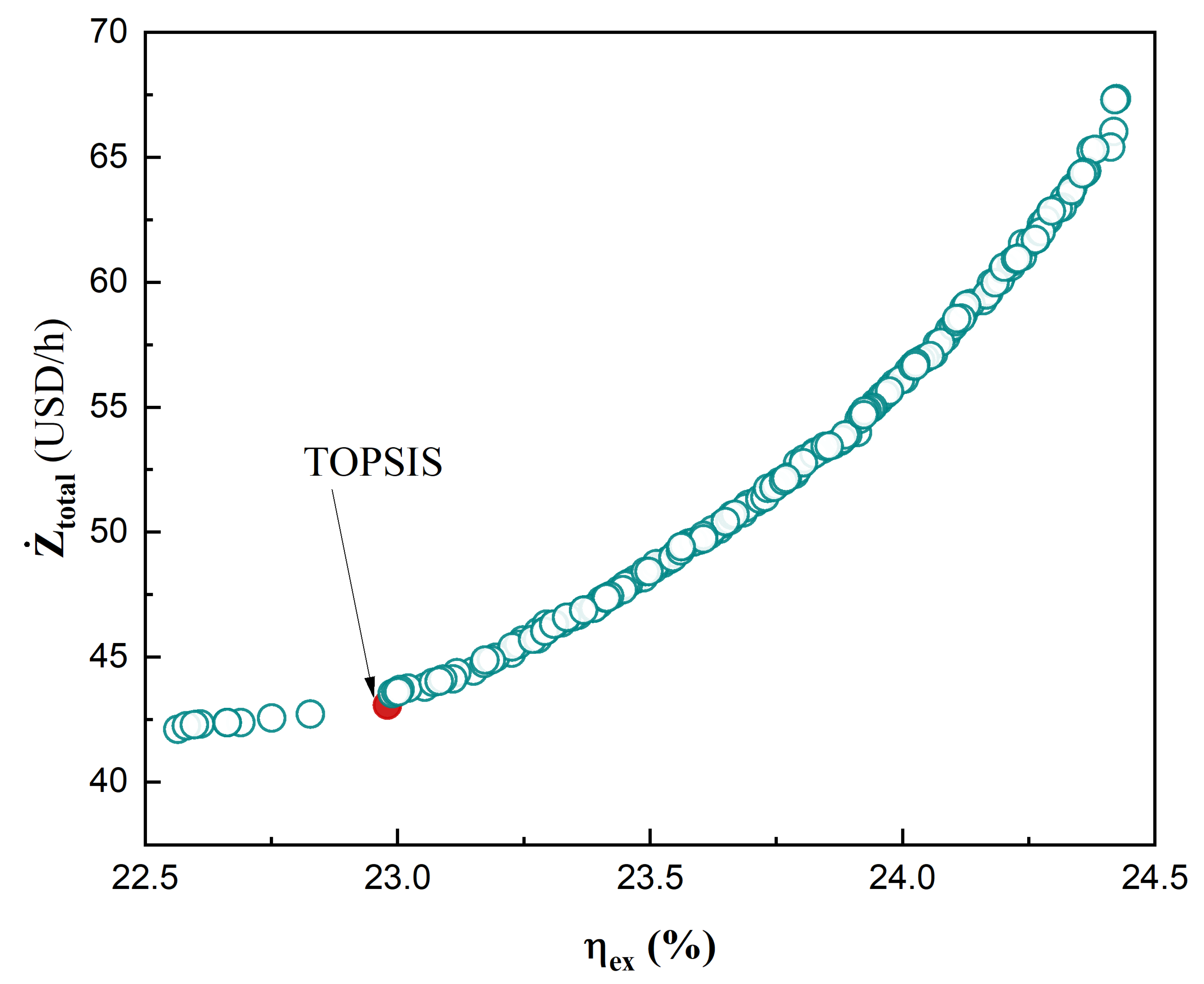
  • The technique for order preference by similarity to ideal situation (TOPSIS) method is employed as a decision-making tool to determine the optimal configuration for the cogeneration system.

2. Materials and Methods

The schematic diagram of the cogeneration hybrid system is illustrated in Figure 1. The operational process of the system can be elucidated as follows: the working fluid (WF) of the PTC, specifically Dowtherm A, undergoes heating through solar radiation when exposed to sunlight. The working fluid (WF), Dowtherm A, undergoes a process wherein it passes through the evaporator. Following a heat exchange with the waste incineration’s WF, Dowtherm A is then returned to the solar collector to complete the cycle. In the waste incineration cycle, utilizing Therminol VP-1 as the WF, the fluid is overheated at point 5. Subsequently, it proceeds through a heat exchanger. During nighttime, in the absence of solar irradiation, the heat transfer oil is directly heated by the waste incineration system, ensuring that the temperature at point 6 reaches the predetermined set temperature. The WF in the ORC (Toluene) is in a superheated state at point 9. After going through the turbine, the generated power goes to the industry. The introduction of the third heat exchanger (HE3) is to improve the energy efficiency of the system. For the ORC, the thermoelectric generator (TEG) is used instead of the condenser to improve the overall efficiency of the hybrid system. After condensation for TEG, the medium temperature heat (for distinct heat) at point 16 is going to the resident, and after the three HEs, the WF is back to point 9 to complete the cycle.

2.1. Parabolic Trough Collector (PTC)

When exposed to solar radiation, the solar collectors efficiently absorb an increased amount of heat from the sun. Subsequently, this accumulated heat is transferred to the WF as it passes through the PTCs. The design parameters of the PTC are shown in Table 1. The calculation of the rate at which collectors generate useful energy can be determined as [25]:
Q ˙ u = N · F R · [ ( S AR · A a ) ( A r · U L · ( T in T 0 ) ) ]
Q ˙ u = m ˙ 1 ( h 1 h 4 )
where A r and A a denote the areas of receiver and aperture, N is the number of solar collectors. T 0 represents the room temperature, meanwhile, and T in refers to the inlet temperature of the PTC. Furthermore, U L represents the heat loss coefficient, F R is the heat loss factor, and S AR , which is the absorbed solar radiation, can be determined as [26]
S AR = G b · τ p · τ c · α · γ
F R = m ˙ C · C p , C A r · U L · ( 1 exp ( F CL · A r · U L m ˙ C · C p , C ) )
where C p , C is the specific heat of the WF in the solar cycle, and m ˙ C is the mass flow rate of Dowtherm A. F CL is the efficiency factor of solar collector and can be calculated as follows [27]:
F CL = 1 / U L 1 / U L + D o , r h fi + ( D o , r 2 k · ln D o , r D i , r )
where D o , r is the outside diameter of the PTC, and D i , r denotes the inside diameter. Additionally, the receiver’s thermal conductivity is denoted by k. The following method can be used to calculate the aperture’s area [27]:
A a = L · ( W D o , r )
where W and L denote the width and length of the receiver.

2.2. Waste Incineration Cycle (WI)

The average lower heating value (LHV) of the waste source is an efficient method of determining the energy level discharged in the waste incineration (WI) unit. The reported LHV, assuming uniform waste distribution, is around 12,500 kJ/kg [28]. The following is a description of this process’s thermal power:
Q ˙ WI = η WI · m ˙ WI · LHV
where m ˙ WI is the mass flow rate of the solid waste, and η WI is the efficiency of the WI unit, which is assumed to be 80% in this work. For the WI unit, the chemical exergy should be calculated during the process. The chemical exergy of the municipal solid waste can be described as [29]:
E ˙ xWI = LHV × m ˙ WI ( 1.0064 + 0.1519 H / C + 0.0616 O / C + 0.0429 N / C )
where nitrogen, carbon, hydrogen, and oxygen are represented by N, C, H, and O, respectively. The weight percentage of the solid waste is shown in Table 2.

2.3. Organic Rankine Cycle (ORC)

The organic Rankine cycle (ORC) normally contains four parts which are a turbine, pump, evaporator, and condenser; in the present work, to improve the energy efficiency of the system, a TEG was employed instead of the condenser. The parameter that describes the ability of the TEG is efficiency, which can be described as [31]:
η TEG = η C 1 + ZT m 1 1 + ZT m + T L T H
η C = 1 T L T H
T H = 1 2 ( T 11 + T 12 )
T L = 1 2 ( T 16 + T 17 )
where η C denotes the Carnot efficiency, and ZT m is the thermoelectric figure of merit. The energy balance equation of TEG unit is represented by:
m ˙ 11 h 11 + m ˙ 17 h 17 = m ˙ 12 h 12 + m ˙ 16 h 16 + W ˙ TEG
η TEG = W ˙ TEG m ˙ 11 ( h 11 h 12 )
The energy balance equations of the ORC are presented in Table 3.

2.4. Exergy Analysis

A useful method for assessing a thermodynamic system’s performance is exergy analysis. Exergy analysis considers the availability and quality of energy present in the system, enabling a more thorough evaluation of its functionality and efficiency. Typically, exergy is dissected into four distinct components. However, in the current study, our analysis focused exclusively on the physical and chemical facets of exergy, neglecting the consideration of kinetic and potential exergy components. The following formula can be used to determine the physical and chemical exergy rate [31].
E ˙ xi ph = m ˙ [ ( h i h 0 ) T 0 ( s i s 0 ) ]
ex ¯ ch = i = 1 n x i ex ¯ ch i + RT 0 n = 1 n x i ln ( x i )
where h i and s i represent the enthalpy and entropy of the ith component, respectively. The subscript 0 signifies parameters corresponding to the reference state. x i denotes the mole fraction and ex ¯ ch i represents the standard exergy of the constituents. The proposed system’s rate of exergy destruction can be stated as follows [32]:
E ˙ x Q + m ˙ in ex ¯ in = E ˙ x W + m ˙ out ex ¯ out + E ˙ x D
The system’s exergy efficiency can be represented as follows:
η ex = ( W ˙ net + E ˙ x 16 ) × t Day E ˙ xsun × t sun + E ˙ x 17 × t Day + E ˙ x WI
The exergy balance equations of each unit are shown in Table 4.

2.5. Economic Analysis

Accounting for economic analyses—especially hourly costs—will yield a comprehensive knowledge of the proposed systems. The total investment cost encompasses capital expenditures and ongoing operation and maintenance costs. The formula utilized to ascertain the total investment rate is as follows [34]:
Z ˙ k = Z k · CRF φ τ
where φ denotes the maintenance factor, which is assumed to be 1.06 in this work; Z k stands for the capital invested in each component, CRF for the capital recovery factor (0.11), and τ for the number of working hours annually (7446 h).
CRF = i · ( 1 + i ) n ( 1 + i ) n 1
where i is the interest rate, which is 0.1, and n is the life time of the system (20 years). The cost of a heat exchanger is heavily influenced by the heat transfer area. One approach to determining this area is to use the following formulas [35]:
A i = Q ˙ i Δ T m U i
Δ T m = Δ T 1 Δ T 2 ln Δ T 1 Δ T 2
where Q ˙ i represents the flow rate of heat transfer, U i denotes the heat transfer coefficient, Δ T m means the Logarithmic Mean Temperature Difference (LMTD). The capital investment of each component is given in Table 5.

3. Results and Discussion

3.1. Validation

Regarding the novel aspect of the suggested system, a thorough verification of its essential elements was carried out to maintain the precision of the analytical findings. The data in our system were validated against the findings reported in the articles authored by Yu et al. [12], and Yang et al. [37]. During the validation process, the ORC was utilized as the benchmark. To enhance system efficiency, the TEG was integrated into our present work. However, to maintain consistency between the two systems, the output power of the TEG was not considered. With identical input parameters, the exergy efficiencies of the three systems were measured at 22.2%, 24.3%, and 24.3%, respectively. The validation results show remarkable alignment with the conclusions presented in the referenced works. Table 6 represents the details of the validation results.

3.2. ANN

The thermodynamic properties and modeling of the system were simulated using Engineering Equation Solver (EES). The working fluids for the PTC, WI, and ORC were Dowtherm A, Therminol VP1, and Toluene, respectively. The flowchart of the proposed system is shown in Figure 2. The simulation process can be outlined as follows: after thermodynamic modeling, 1000 randomly generated datasets were inputted into an ANN. By leveraging the ANN, the system demonstrates its capability to predict outputs accurately, with optimal precision, minimal complexity, and reduced computational expense. The ANN serves as a dependable tool in energy systems for predicting outputs based on primary input characteristics.
The 1000 random data points were divided into three subsets: training (70%), testing (15%), and validation (15%). To achieve optimal system performance, the NSGA II algorithm was employed for system optimization. Following optimization, the Pareto frontier revealed several viable solutions. Subsequently, the TOPSIS decision-making method was employed to select the best solution. The optimization criteria included the hourly cost of the system ( Z ˙ tot ) and the exergy efficiency of the system ( η ex ). Given that both parameters were of equal importance, equal weights were assigned to them.
The validation result of the ANN is presented in Figure 3. The coefficient of determination (R), which has the highest accuracy at the value of 1 on the y = x line, shows the difference between the actual and predicted outputs. The values of the correlation coefficient (R) for the hourly cost and exergy efficiency are 1 and 0.99998, respectively. This high level of consistency between the actual and predicted values serves as compelling evidence of the accuracy of the ANN.

3.3. Parametric Analysis

To ascertain the influence of different input parameters on exergy efficiency and the hourly cost rate of the system, a parametric study was conducted. The total area of the PTC ( A tot ) and the inlet temperature of the evaporator ( T 2 ) were sensitive to Z ˙ tot and η ex . Figure 4 presents the influence of the A tot and T 2 on the performance of the system. The cost of the PTC was included in the initial investment, and an increase in the number of collectors led to a rise in the hourly cost. A peak value was observed at 9000 m 2 , with a corresponding hourly cost rate of USD   69.13 / h . According to Equation (18), there exists a linear relationship between exergy efficiency and net output power. An increase in the number of collectors leads to a rise in net output power, consequently increasing exergy efficiency. A peak value was also observed at 9000 m 2 , where the exergy efficiency reached 24.49%. The parameter T 2 exerted a significant impact on the system’s performance. T 2 ranged from 350 °C to 380 °C, with the minimum efficiency ( η ex ) observed at 380 °C, registering at 21.31%. Correspondingly, the Z ˙ tot exhibited a similar pattern. At T 2 = 350 °C, Z ˙ tot peaked at USD   42.84 / h .
Two additional crucial parameters significantly impacting the system’s performance were the turbine inlet temperature ( T 9 ) and the output temperature of the WI unit ( T 6 ). The impact of these parameters is graphically depicted in Figure 5. As the T 9 and the T 6 increased, the output parameters Z ˙ tot and η ex demonstrated a corresponding increase. This rise in T 9 and T 6 led to an increase in net output power, consequently boosting the exergy efficiency. Moreover, the elevated temperatures led to a larger heat transfer area, consequently driving up the initial investment costs.

3.4. Multi-Objective Optimization

Deb [38] introduced the widely used multi-objective optimization method NSGA-II in 2002. The main concept of NSGA-II can be succinctly articulated as follows. Initially, a population is randomly generated, and through the fundamental genetic algorithm procedures of selection, crossover, and mutation, an offspring population is produced. Secondly, from the second generation onward, the parent and offspring populations are merged for expedited, non-dominated sorting. This sorting process is pivotal in ascertaining the crowding degree of each individual within every layer. Ultimately, until the termination criteria for the program are met, new offspring populations are iteratively generated utilizing the core functions of the genetic algorithm [39].
In the current study, to achieve optimal system performance, NSGA-II was implemented for system optimization. Based on the parametric analysis, four input parameters were selected as the optimized input variables: A tot , T 2 , T 9 , and T 6 . The output optimization variables were Z ˙ tot and η ex . The respective ranges of variation for these parameters are detailed in Table 7. For the NSGA-II process, the following parameters were employed: a population size of 200 individuals, a crossover fraction of 0.7, a migration fraction of 0.4, and a maximum of 100 generations.
Figure 6 depicts the Pareto optimal solutions frontier, illustrating a trade-off between the hourly cost of the system and the exergy efficiency. Through non-dominated sorting and crowding distance analysis in the goal space, this front reveals a comprehensive set of solutions for the system. It is evident from Figure 6 that any alteration in one response has a consequential impact on the other response. Specifically, an increase in exergy efficiency correlates with an increase in the hourly cost. The Pareto frontier indeed presents a collection of equivalent solutions, necessitating the intervention of a decision-maker to discern the optimal solution.
Utilizing distances to both ideal and anti-ideal points, TOPSIS emerges as a robust multi-criteria decision analysis technique adept at ranking items on a scale from ideal to non-ideal solutions. Vectors are commonly employed to furnish descriptions of options regarding the features under consideration [40]. This method aims to select the alternative with the smallest distance to the ideal solutions, thereby optimizing the decision outcome. The TOPSIS point of this work is marked in Figure 6, and the relevant details are present in Table 8. The best solution chosen by TOPSIS shows that the exergy efficiency of the system is 22.98% and the initial hourly cost is USD 43.08/h.

3.5. Economic Analysis

Figure 7 illustrates the hourly cost distribution for each component of the system. The system was categorized into seven main parts: the evaporator, turbine, HEX, TEG, solar collector, pump, and the WI unit. The total hourly cost amounts to USD 43.08, with the solar collector emerging as the costliest component at USD 22.9/h, which accounts for 53.2% of the total hourly cost. The ORC turbine, priced at USD 8.566 per hour, constitutes the second-largest hourly expense, amounting to 19.9% of the total initial hourly cost. Next are the TEG, WI unit, and evaporator, which account for 11.2%, 8.7%, and 3.8% of the total initial hourly cost, respectively. The ones that cost the least are the HEX and pump, which occupy 2% and 1.2%, respectively. The corresponding details are given in Table 9.
Based on Figure 7, it is evident that the cost of solar collectors influenced the economic performance. Therefore, future efforts will focus on mitigating the investment required for solar collectors. This may involve exploring avenues such as optimizing working fluid selection or integrating nanoparticles into the working fluid.

4. Conclusions

The primary focus of this investigation centered around designing a pioneering hybrid solar–waste power plant utilizing an ORC. The WI unit was integrated to solve the intermittent challenge of solar energy. The TEG was incorporated into the system, replacing the traditional condenser in the ORC, to enhance the cycle’s output power. The created models were optimized by combining NSGA II and ANN optimization techniques, and the Pareto optimal frontier was used to show the best results. In the set of optimization results, the TOPSIS decision-making method was employed to select the optimal solution for the system.
The parametric analysis reveals that four input parameters—the total area of the solar collector ( A tot ), the output temperature of the PTC ( T 2 ), the inlet temperature of the turbine ( T 9 ), and the outlet temperature of the WI ( T 6 )—significantly influence the performance of the system. The hourly cost of the initial investment ( Z ˙ tot ) and the exergy efficiency ( η ex ) increase with the A tot , T 6 , and T 9 , but decrease as the T 2 increases. The Pareto frontier also presents a set of optimal points that choose the Z ˙ tot and η ex as optimization variables. TOPSIS identifies the best solution as the one with an hourly cost of the initial investment at USD 43.08/h and an exergy efficiency of 22.98%. Under this condition, the A tot , T 2 , T 9 , and T 6 are 5705.82 m2, 348.27 °C, 279.83 °C, and 394.33 °C, respectively.
The economic analysis reveals that the solar collector constitutes the most significant portion of the total initial hourly cost, accounting for 53.2%, equivalent to USD 22.9/h. The ranking of the remaining components in terms of their contribution to the total initial hourly cost is as follows: turbine (19.9%), TEG (11.2%), WI (8.7%), evaporator (3.8%), HEX (2%), and pump (1.2%). Future work can focus on reducing the cost of the solar collector, for instance, by exploring alternative working fluids to enhance its efficiency.

Author Contributions

Conceptualization, methodology, software, and writing—original draft preparation, L.W.; validation, formal analysis, and investigation, J.Y.; resources, data curation, and writing—review and editing, B.Q.; visualization, supervision, and project administration, C.P. All authors have read and agreed to the published version of the manuscript.

Funding

This research received no external funding.

Data Availability Statement

The original contributions presented in the study are included in the article, further inquiries can be directed to the corresponding author.

Acknowledgments

The authors express their gratitude to Seyed Mojtaba Alirahmi for technical support.

Conflicts of Interest

The authors declare no conflicts of interest.

References

  1. Zhang, Y.; Ma, S.; Yue, W.; Tian, Z.; Yang, C.; Gao, W. Energy, Exergy, Economic and Environmental (4E) Evaluation of a Solar-Integrated Energy System at Medium–High Temperature Using CO2 as the Parabolic Trough Collector (PTC) Working Medium. Energy Convers. Manag. 2023, 296, 117683. [Google Scholar] [CrossRef]
  2. Belgasim, B.; Aldali, Y.; Abdunnabi, M.J.R.; Hashem, G.; Hossin, K. The Potential of Concentrating Solar Power (CSP) for Electricity Generation in Libya. Renew. Sustain. Energy Rev. 2018, 90, 1–15. [Google Scholar] [CrossRef]
  3. Alami, A.H.; Olabi, A.G.; Mdallal, A.; Rezk, A.; Radwan, A.; Rahman, S.M.A.; Shah, S.K.; Abdelkareem, M.A. Concentrating Solar Power (CSP) Technologies: Status and Analysis. Int. J. Thermofluids 2023, 18, 100340. [Google Scholar] [CrossRef]
  4. Elfeky, K.E.; Wang, Q. Techno-Environ-Economic Assessment of Photovoltaic and CSP with Storage Systems in China and Egypt under Various Climatic Conditions. Renew. Energy 2023, 215, 118930. [Google Scholar] [CrossRef]
  5. Ghazouani, M.; Bouya, M.; Benaissa, M. Thermo-Economic and Exergy Analysis and Optimization of Small PTC Collectors for Solar Heat Integration in Industrial Processes. Renew. Energy 2020, 152, 984–998. [Google Scholar] [CrossRef]
  6. Bisinella, V.; Hulgaard, T.; Riber, C.; Damgaard, A.; Christensen, T.H. Environmental Assessment of Carbon Capture and Storage (CCS) as a Post-Treatment Technology in Waste Incineration. Waste Manag. 2021, 128, 99–113. [Google Scholar] [CrossRef] [PubMed]
  7. Council of the European Union. Directive (EU) 2018/851 of the European Parliament and of the Council of 30 May 2018 amending Directive 2008/98/EC on waste. Off. J. Eur. Union 2018, 150, 109–140. [Google Scholar]
  8. Lombardi, L.; Castaldi, M.J. Energy Recovery from Residual Municipal Solid Waste: State of the Art and Perspectives within the Challenge to Climate Change. Energies 2024, 17, 395. [Google Scholar] [CrossRef]
  9. Eurostat. Municipal Waste Statistics. Available online: https://ec.europa.eu/eurostat/statistics-explained/index.php?title=Municipal_waste_statistics#Municipal_waste_treatment (accessed on 10 February 2024).
  10. Pan, M.; Chen, X.; Li, X. Multi-Objective Analysis and Optimization of Cascade Supercritical CO2 Cycle and Organic Rankine Cycle Systems for Waste-to-Energy Power Plant. Appl. Therm. Eng. 2022, 214, 118882. [Google Scholar] [CrossRef]
  11. Amulen, J.; Kasedde, H.; Serugunda, J.; Lwanyaga, J.D. The Potential of Energy Recovery from Municipal Solid Waste in Kampala City, Uganda by Incineration. Energy Convers. Manag. X 2022, 14, 100204. [Google Scholar] [CrossRef]
  12. Yu, H.; Helland, H.; Yu, X.; Gundersen, T.; Sin, G. Optimal Design and Operation of an Organic Rankine Cycle (ORC) System Driven by Solar Energy with Sensible Thermal Energy Storage. Energy Convers. Manag. 2021, 244, 114494. [Google Scholar] [CrossRef]
  13. Wang, L.; Teles, M.P.R.; Yu, H.; Silva, B.V.F.; Arabkoohsar, A. Waste Incineration and Heat Recovery Hybridized with Low-Focus Fresnel Lens Solar Collectors for Sustainable Multi-Generation; A Thorough Techno-Economic-Environmental Analysis and Optimization. Chemosphere 2024, 346, 140409. [Google Scholar] [CrossRef] [PubMed]
  14. Alirahmi, S.M.; Gundersen, T.; Arabkoohsar, A.; Klemeš, J.J.; Sin, G.; Yu, H. Process Design, Integration, and Optimization of a Novel Compressed Air Energy Storage for the Coproduction of Electricity, Cooling, and Water. Renew. Sustain. Energy Rev. 2024, 189. [Google Scholar] [CrossRef]
  15. Li, D.; Rao, Z.; Zhuo, Q.; Chen, R.; Dong, X.; Liu, G.; Liao, S. Case Studies in Thermal Engineering Resource Endowments Effects on Thermal-Economic Efficiency of ORC-Based Hybrid Solar-Geothermal System. Case Stud. Therm. Eng. 2023, 52, 103739. [Google Scholar] [CrossRef]
  16. Yang, F.; Cho, H.; Zhang, H.; Zhang, J.; Wu, Y. Artificial Neural Network (ANN) Based Prediction and Optimization of an Organic Rankine Cycle (ORC) for Diesel Engine Waste Heat Recovery. Energy Convers. Manag. 2018, 164, 15–26. [Google Scholar] [CrossRef]
  17. Feng, Y.; Liu, Y.Z.; Wang, X.; He, Z.X.; Hung, T.C.; Wang, Q.; Xi, H. Performance Prediction and Optimization of an Organic Rankine Cycle (ORC) for Waste Heat Recovery Using Back Propagation Neural Network. Energy Convers. Manag. 2020, 226, 113552. [Google Scholar] [CrossRef]
  18. Alirahmi, S.M.; Gundersen, T.; Yu, H. A Comprehensive Study and Tri-Objective Optimization for an Efficient Waste Heat Recovery from Solid Oxide Fuel Cell. Int. J. Hydrogen Energy 2024, 52, 663–680. [Google Scholar] [CrossRef]
  19. Palagi, L.; Pesyridis, A.; Sciubba, E.; Tocci, L. Machine Learning for the Prediction of the Dynamic Behavior of a Small Scale ORC System. Energy 2019, 166, 72–82. [Google Scholar] [CrossRef]
  20. Verma, S.; Pant, M.; Snasel, V. A Comprehensive Review on NSGA-II for Multi-Objective Combinatorial Optimization Problems. IEEE Access 2021, 9, 57757–57791. [Google Scholar] [CrossRef]
  21. Cao, Y.; Dhahad, H.A.; Alsharif, S.; El-Shorbagy, M.A.; Sharma, K.; Anqi, A.E.; Rashidi, S.; Shamseldin, M.A.; Shafay, A.S. Predication of the Sensitivity of a Novel Daily Triple-Periodic Solar-Based Electricity/Hydrogen Cogeneration System with Storage Units: Dual Parametric Analysis and NSGA-II Optimization. Renew. Energy 2022, 192, 340–360. [Google Scholar] [CrossRef]
  22. Bedakhanian, A.; Maleki, A.; Haghighat, S. Multi-Objective Optimization of a Cogeneration System Based on Solar Energy for Clean Hydrogen, Cooling, and Electricity Production. Case Stud. Therm. Eng. 2024, 54, 103990. [Google Scholar] [CrossRef]
  23. Özahi, E.; Tozlu, A. Optimization of an Adapted Kalina Cycle to an Actual Municipal Solid Waste Power Plant by Using NSGA-II Method. Renew. Energy 2020, 149, 1146–1156. [Google Scholar] [CrossRef]
  24. Alirahmi, S.M.; Assareh, E. Energy, Exergy, and Exergoeconomics (3E) Analysis and Multi-Objective Optimization of a Multi-Generation Energy System for Day and Night Time Power Generation—Case Study: Dezful City. Int. J. Hydrogen Energy 2020, 45, 31555–31573. [Google Scholar] [CrossRef]
  25. Wang, L.; Zhou, C.; Rahbari, H.R. Optimizing Solar Energy Harvesting through Integrated Organic Rankine Cycle–Reverse Osmosis Systems: A Techno–Economic Analysis. Sustainability 2023, 15, 13602. [Google Scholar] [CrossRef]
  26. Alirahmi, S.M.; Rahmani Dabbagh, S.; Ahmadi, P.; Wongwises, S. Multi-Objective Design Optimization of a Multi-Generation Energy System Based on Geothermal and Solar Energy. Energy Convers. Manag. 2020, 205, 112426. [Google Scholar] [CrossRef]
  27. Assareh, E.; Alirahmi, S.M.; Ahmadi, P. A Sustainable Model for the Integration of Solar and Geothermal Energy Boosted with Thermoelectric Generators (TEGs) for Electricity, Cooling and Desalination Purpose. Geothermics 2021, 92, 102042. [Google Scholar] [CrossRef]
  28. Arabkoohsar, A.; Nami, H. Thermodynamic and Economic Analyses of a Hybrid Waste-Driven CHP–ORC Plant with Exhaust Heat Recovery. Energy Convers. Manag. 2019, 187, 512–522. [Google Scholar] [CrossRef]
  29. Sajid Khan, M.; Huan, Q.; Lin, J.; Zheng, R.; Gao, Z.; Yan, M. Exergoeconomic Analysis and Optimization of an Innovative Municipal Solid Waste to Energy Plant Integrated with Solar Thermal System. Energy Convers. Manag. 2022, 258, 115506. [Google Scholar] [CrossRef]
  30. Nami, H.; Arabkoohsar, A. Improving the Power Share of Waste-Driven CHP Plants via Parallelization with a Small-Scale Rankine Cycle, a Thermodynamic Analysis. Energy 2019, 171, 27–36. [Google Scholar] [CrossRef]
  31. Alirahmi, S.M.; Assareh, E.; Arabkoohsar, A.; Yu, H.; Hosseini, S.M.; Wang, X. Development and Multi-Criteria Optimization of a Solar Thermal Power Plant Integrated with PEM Electrolyzer and Thermoelectric Generator. Int. J. Hydrogen Energy 2022, 47, 23919–23934. [Google Scholar] [CrossRef]
  32. Sadreddini, A.; Fani, M.; Ashjari Aghdam, M.; Mohammadi, A. Exergy Analysis and Optimization of a CCHP System Composed of Compressed Air Energy Storage System and ORC Cycle. Energy Convers. Manag. 2018, 157, 111–122. [Google Scholar] [CrossRef]
  33. Alirahmi, S.M.; Bashiri Mousavi, S.; Razmi, A.R.; Ahmadi, P. A Comprehensive Techno-Economic Analysis and Multi-Criteria Optimization of a Compressed Air Energy Storage (CAES) Hybridized with Solar and Desalination Units. Energy Convers. Manag. 2021, 236, 114053. [Google Scholar] [CrossRef]
  34. Alenezi, A.; Vesely, L.; Kapat, J. Exergoeconomic Analysis of Hybrid SCO2 Brayton Power Cycle. Energy 2022, 247, 123436. [Google Scholar] [CrossRef]
  35. da Silva Morais, P.H.; Lodi, A.; Aoki, A.C.; Modesto, M. Energy, Exergetic and Economic Analyses of a Combined Solar-Biomass-ORC Cooling Cogeneration Systems for a Brazilian Small Plant. Renew. Energy 2020, 157, 1131–1147. [Google Scholar] [CrossRef]
  36. Alirahmi, S.M.; Ebrahimi-Moghadam, A. Comparative Study, Working Fluid Selection, and Optimal Design of Three Systems for Electricity and Freshwater Based on Solid Oxide Fuel Cell Mover Cycle. Appl. Energy 2022, 323, 119545. [Google Scholar] [CrossRef]
  37. Yang, J.; Li, J.; Yang, Z.; Duan, Y. Thermodynamic Analysis and Optimization of a Solar Organic Rankine Cycle Operating with Stable Output. Energy Convers. Manag. 2019, 187, 459–471. [Google Scholar] [CrossRef]
  38. Deb, K.; Pratap, A.; Agarwal, S.; Meyarivan, T. A Fast and Elitist Multiobjective Genetic Algorithm: NSGA-II. IEEE Trans. Evol. Comput. 2002, 6, 182–197. [Google Scholar] [CrossRef]
  39. Xu, C.; Ke, Y.; Li, Y.; Chu, H.; Wu, Y. Data-Driven Configuration Optimization of an off-Grid Wind/PV/Hydrogen System Based on Modified NSGA-II and CRITIC-TOPSIS. Energy Convers. Manag. 2020, 215, 112892. [Google Scholar] [CrossRef]
  40. Susmaga, R.; Szczech, I.; Brzezinski, D. Towards Explainable TOPSIS: Visual Insights into the Effects of Weights and Aggregations on Rankings. Appl. Soft Comput. 2023, 153, 111279. [Google Scholar] [CrossRef]
Figure 1. The schematic of the cogeneration hybrid system.
Energies 17 01810 g001
Figure 2. The flowchart of the proposed system.
Energies 17 01810 g002
Figure 3. The ANN validation of the two output parameters.
Energies 17 01810 g003
Figure 4. The influence of A tot (a) and T 2 (b) on the system’s hourly cost and exergy efficiency.
Energies 17 01810 g004
Figure 5. The influence of T 9 (a) and T 6 (b) on the system’s hourly cost and exergy efficiency.
Energies 17 01810 g005
Figure 6. The optimal points of the system (Pareto frontier).
Energies 17 01810 g006
Figure 7. The hourly cost diagram of the system.
Energies 17 01810 g007
Table 1. Design parameters and input values for the PTC [26].
ParametersValueUnit
Absorptivity of the receiver ( α )0.96-
Effective transmissivity of PTC ( τ p )0.94-
Heat loss coefficient ( U L )3.82W/m2°C
Correction factor for diffuse radiation ( γ )0.95-
Thermal conductivity of the receiver (K)16W/m2°C
Heat transfer coefficient inside the receiver ( h fi )300W/m2°C
Receiver inside diameter ( D i , r )0.066m
Receiver outside diameter ( D o , r )0.07m
Transmissivity of the cover glazing ( τ c )0.96-
Single collector length (L)12.27m
Single collector width (W)5.76m
Direct normal irradiance ( G b )850W/m2
Table 2. The weight percentage of the municipal solid waste [30].
ParametersValue (%)
Carbon47.18
Oxygen39.57
Hydrogen6.25
Ash5.91
Nitrogen0.91
Sulphur0.18
Table 3. The energy balance equations of the ORC.
ComponentsEnergy Balance Equations
IHE1 m ˙ 7 ( h 6 h 7 ) = m ˙ 15 ( h 9 h 15 )
IHE2 m ˙ 7 ( h 7 h 8 ) = m ˙ 15 ( h 15 h 14 )
Turbine W ˙ Tur = m ˙ 9 h 9 m ˙ 10 h 10
IHE3 m ˙ 10 ( h 10 h 11 ) = m ˙ 14 ( h 14 h 13 )
Pump3 W ˙ Pump 3 = m ˙ 13 ( h 13 h 12 )
Table 4. The exergy balance equations of the system [33].
ComponentExergy Balance Equations
PTC E ˙ x Sun + E ˙ x 4 = E ˙ x 1 + E ˙ x Sun D
Pump1 E ˙ x 1 + W ˙ Pump 1 = E ˙ x 2 + E ˙ x P 1 D
Pump2 E ˙ x 3 + W ˙ Pump 2 = E ˙ x 4 + E ˙ x P 2 D
Evaporator E ˙ x 8 + E ˙ x 2 = E ˙ x 5 + E ˙ x 3 + E ˙ x Eva D
WI E ˙ x WH + E ˙ x 5 = E ˙ x 6 + E ˙ x WI D
IHE1 E ˙ x 6 + E ˙ x 15 = E ˙ x 7 + E ˙ x 9 + E ˙ x IHE 1 D
IHE2 E ˙ x 7 + E ˙ x 14 = E ˙ x 8 + E ˙ x 15 + E ˙ x IHE 2 D
Turbine E ˙ x 9 = E ˙ x 10 + W ˙ Tur + E ˙ x Tur D
IHE3 E ˙ x 10 + E ˙ x 13 = E ˙ x 11 + E ˙ x 14 + E ˙ x IHE 3 D
Turbine E ˙ x 10 = E ˙ x 11 + E ˙ x 13 + W ˙ Tur + E ˙ x DTur
Pump3 E ˙ x 12 + W ˙ Pump 3 = E ˙ x 13 + E ˙ x P 3 D
TEG E ˙ x 11 + E ˙ x 17 = E ˙ x 12 + E ˙ x 16 + E ˙ x TEG D
Table 5. Each component’s investment cost rate, based on references [29,36].
ComponentCapital Expense Function (USD)
PTC Z SC = 240   A a N
Evaporator Z Eva = 276   A Eva 0.88
WI Z WI = 2567   ( 3600   m WI ) 0.67
Pumps Z Pump = 3540   W ˙ Pump 0.71
TEG Z TEG = 1500   W ˙ TEG
Turbine Z Tur = 4750   W ˙ Tur 0.7
IHE Z IHE = 12000   ( A IHE 100 ) 0.6  
Table 6. The validation results of the proposed system with Toluene as the working fluid.
P E V A   ( b a r ) T T u r i n l e t   ( ° C ) η O R C (%)
Yang et al. [37]37.12311.522.2
Yu et al. [12]37.12313.324.3
This work37.12313.324.3
Table 7. The input and output parameters for NSGA II.
Input Range Output Aim
The total area of the PTC 5000 A tot 8000 Z ˙ tot To be minimized
The inlet temperature of the evaporator 350   T 2 380   η ex To be maximized
The inlet temperature of the turbine 260   T 9 280  
The outlet temperature of the WI 380   T 6 400  
Table 8. The relevant details of the TOPSIS point.
ParametersTOPSIS Value
T 9   (°C)279.83
T 2   (°C)348.27
T 6   (°C)394.33
A Tol   ( m 2 )5705.82
η ex (%)22.98
Z ˙ tot   (USD/h)43.08
Table 9. The economic analysis detail of each component.
ElementsHourly Cost (USD/h)Percentage (%)
Evaporator1.6253.8
Turbine8.56619.9
HEX0.8742
TEG4.82111.2
Solar collector22.953.2
Pump0.5291.2
WI3.7668.7
Disclaimer/Publisher’s Note: The statements, opinions and data contained in all publications are solely those of the individual author(s) and contributor(s) and not of MDPI and/or the editor(s). MDPI and/or the editor(s) disclaim responsibility for any injury to people or property resulting from any ideas, methods, instructions or products referred to in the content.

