

Future Distribution Networks: A Review


1
Department of Electrical and Electronics Engineering, The Hong Kong Polytechnic University, Hung Hom, Kowloon, Hong Kong
2
School of Engineering, Manchester Metropolitan University, John Dalton Building, Chester Street, Manchester M15 GD, UK
3
Department of Electrical and Electronics Engineering, Middle East Technical University, Ankara 06800, Turkey
*
Author to whom correspondence should be addressed.
Energies 2024, 17(8), 1822; https://doi.org/10.3390/en17081822
Submission received: 8 February 2024
/
Revised: 2 April 2024
/
Accepted: 6 April 2024
/
Published: 10 April 2024
(This article belongs to the Collection Review Papers in Energy and Environment)
Abstract
:This manuscript presents a comprehensive review of recent advancements in electrical distribution networks, with a specific focus on the incorporation of direct current (DC) applications. The research aims to comprehensively address the current and future aspects of DC, spanning from the distribution level to the utilization level. The renewed interest in DC power systems has led to the investigation of several transitional challenges in recent years. A significant portion of these efforts has been dedicated to determining the feasibility of applying DC to specific use cases. Additionally, the literature has explored design considerations such as system architecture and voltage levels, the integration of DC into existing distribution networks, load flow (LF) computations, and the distinct safety concerns associated with DC power systems. In this paper, the various research endeavors are categorized, evaluated, and scrutinized to assess the current state of the transition from a purely alternating current (AC) distribution system to a solely DC or hybrid AC/DC distribution system. A bibliometric analysis is conducted, constructing a network of co-occurrence based on author-provided keywords, which reveals the primary research foci in this domain. The barriers hindering the widespread adoption of DC distribution systems and potential solutions are also discussed. Moreover, this article synthesizes ongoing efforts to address these obstacles and delineates future research directions by emphasizing the existing knowledge gaps.
1. Introduction
In recent times, a renewed discussion has emerged regarding the utilization of alternating current (AC) and direct current (DC) in power distribution systems. This topic can be traced back to a fervent disagreement that arose at the dawn of the twentieth century, concerning the most efficient means of generating, transmitting, and distributing electrical power. This historical dispute, commonly referred to as the “War of Currents”, involved prominent figures such as George Westinghouse and Nikola Tesla, who advocated for AC, in opposition to Thomas Edison, a staunch proponent of DC. The universal adoption of AC distribution settled the argument for reasons that made perfect sense at the time [1]. The advent of transformers, which offered a simple and effective way of regulating the voltage levels of AC, was one of the reasons. The DC technology at that time was inadequate for regulating voltage levels in transmission and distribution [2].
For over a century, single-phase AC distribution at either 110 V, 60 Hz, or 220 V, 50 Hz has been the prevailing standard, primarily because of the simplicity of voltage conversion through transformers and the advancement of machinery designed for poly-phase AC systems [3]. Nevertheless, it would be prudent to re-evaluate our engineering methods regularly. In the past, such re-evolution has led to efficient and cost-effective high-voltage DC (HVDC) transmission systems for long-distance power transmission [4]. HVDC transmission has established its merit in the modern power system, employing kV-range voltages (hence, small currents), to reduce line losses, and utilizing the whole cross-sectional area of the conductor owing to the elimination of skin effects, thereby transmitting more power than high-voltage AC (HVAC) [5]. In a distribution network for long distribution lines, the impact of inductance and capacitance is significant, and the skin effect must also be taken into consideration. However, for typical residential and commercial voltage drop calculations, these factors may not have much influence.
Since the advent of advanced electronics, most daily use devices, such as phones, televisions, laptops, computers, and even automobiles, have transitioned to DC [6]. DC motors have found their way into washing machines, refrigerators, fans, and heating and cooling systems, enabling greater speed control and efficiency [7]. The widespread adoption of renewable energy power systems based on solar and wind energy is another factor in shifting the power system paradigm to DC [8]. As battery technology has advanced, DC has become the most common type of energy storage [9]. In developed countries, the primary motivations for DC are to increase energy efficiency and conversion to renewable energy sources [10]. However, DC provides the chance to significantly raise the standard of living in developing nations [11]. So, a renewed focus on DC distribution is prompted by the proliferation of DC loads and sources and the resulting ease with which DC voltage can be regulated because of advancements in power electronics. Three significant developments in the last two decades have led to this surge in interest in DC distribution networks. First, the power from solar photovoltaics (PVs) has dropped dramatically in price and is likely to fall more [12]. Second, LED lighting has become widespread globally, making traditional incandescent and fluorescent light bulbs obsolete [13,14,15]. The third and potentially most impactful advancement involves the transition from fossil fuels to more environmentally friendly and efficient methods for electricity generation [16]. Moreover, surveys indicate that economies of scale and technological advancements have contributed to the recent precipitous decline in battery prices [17]. Another factor contributing to the decline in battery prices is the fierce rivalry between major manufacturers.
This study offers a comprehensive literature review and analysis of research centered on DC networks at the distribution and utilization levels, encompassing system design, control, operation, stability, load flow (LF) solutions, protection, and safety issues. It is noteworthy that certain sections of this article incorporate discussions on HVDC to address the broader scope of the subject matter; however, this should not obfuscate the primary focus of this review. This review specifically concentrates on DC and hybrid AC/DC distribution networks. The objectives of this article are to present a cohesive overview of previous work in this field, to indicate potential future research directions, and to provide a framework for locating relevant information. Additionally, this paper aims to offer a streamlined cognitive approach to new researchers regarding the challenges in the widespread adoption of DC in distribution networks and potential solutions.
The rest of this paper is organized as follows: the bibliometric analysis of keywords is presented in Section 2. The motivations to reconsider DC are addressed in Section 3. Feasibility studies on DC distribution are presented in Section 4. Section 5 summarizes LF calculation challenges and the related literature for DC and hybrid AC/DC networks. Protection, safety issues, grounding methods, power quality, and some other challenges for DC are discussed in Section 6. A discussion of DC voltage levels is presented in Section 7. Section 8 presents the possible configurations of DC networks and the adoption of DC into existing AC distribution networks. A summary of research gaps is provided in Section 9. Finally, conclusions are drawn in Section 10.
2. Bibliometric Analysis
Based on 2000 studies published over the last 8 years, VOSviewer software version 1.6.18 [18] was used to construct a network of term co-occurrence linked to “DC distribution network” and “DC distribution system”, which appear in article titles, abstracts, and keywords. The Scopus database was searched using a search within the article title, abstract, and keyword option. VOSviewer has the ability to provide an insightful view of text-mining, and it was utilized to create a co-occurrence of keywords, as shown in Figure 1. There are a total of 4663 keywords, out of which 158 meet the threshold of minimum occurrence for a keyword of more than five times. There are a total of 13 clusters in the network, with a total of 1033 links, and the total link strength is 1585. The 13 clusters are based on 158 selected keywords, and each cluster represents one main area (keyword), as shown in Table 1. The significance of the research is shown by the cumulative keyword network that emerged over time. Table 1 shows the detailed bibliometric analysis based on the authors’ keywords and their relationship with which they appeared in titles, abstracts, and index keywords. This will help readers examine the areas of interest in this research field; moreover, it also highlights the research gaps. Take, for example, cluster number 12, where power flow is the main keyword. It is the weakest among all clusters, which may indicate that it is either overlooked in the literature or there is less interest in this topic for various reasons such as a perceived lack of challenges.
3. Motivations to Reconsider DC
Recent progress in semiconductor technology and power electronic converters has significantly enhanced the capabilities of DC voltage regulation. The proliferation of DC loads, renewable energy sources (RESs), and energy storage systems (ESSs) has stimulated a re-examination of the suitability of DC deployment. These factors will be considered when discussing the superiority of AC or DC systems. Given the current landscape, it is reasonable that DC may emerge as the preferred choice, ousting AC in various applications. DC systems may be used to reduce dependency on fossil fuels and greenhouse gas emissions since they improve the efficiency of energy distribution and make it easier to integrate decentralized RESs. Furthermore, DC will make the Vehicle-to-grid (V2G) operation of electric vehicles (EVs) straightforward [19]. New demand for DC networks at the consumer end will be sparked by the widespread use of distributed generation like PV and the adoption of EVs. Directly connecting PV to an EV’s DC charging port reduces the necessary conversion stages [20]. Interestingly, DC requires fewer outlets because of the widespread usage of USB connections to power portable electronic devices like smartphones, laptops, tablets, etc. Power transfers of up to 100 W are possible through the USB Type-C connection, which is compliant with the new USB Power Delivery 2.0 Standard (20 V at 5 A). Because of differing standards of AC worldwide, universal sockets and plugs can only be utilized with DC [21]. However, standard AC household outlets and plugs cannot be used for DC, and it needs standardization. The necessity to standardize new plugs and sockets stems from the problem of hazardous arcing when removing an active load.
In general, power quality and control are often considered to be more straightforward in AC distribution systems compared with DC distribution systems. This is due to several factors including the following: 1—AC power systems have been in use for a longer time and have well-established standards, equipment, and control mechanisms for managing power quality issues such as voltage regulation, frequency control, and reactive power compensation. The infrastructure and technology for monitoring and controlling AC power systems are more mature and widely available. 2—AC systems inherently support the flow and management of reactive power, which is essential for voltage control and stability. Devices such as capacitors and synchronous condensers can be easily integrated into AC systems to manage reactive power and improve power factors, contributing to better power quality. 3—AC systems are the standard for grid-level power transmission and distribution, and they are well-suited for integrating with existing grid infrastructure. The ability to synchronize and connect AC systems to the grid, as well as the availability of grid codes and standards, makes it easier to control and maintain power quality in AC distribution systems. On the other hand, while DC distribution systems offer advantages such as lower transmission losses and the ability to integrate with certain types of renewable energy sources and energy storage systems, they present unique challenges for power quality and control. These challenges include the need for specialized equipment for voltage and current regulation, fault protection, inrush phenomena, harmonics of upstream converters, and switching components. It is important to note that advancements in power electronics and control technologies are making DC distribution systems more viable and are enabling improved power quality and control. As a result, the ease of power quality and control in AC versus DC distribution systems may evolve as technology advances and as DC systems become more prevalent in certain applications.
It is important to conduct a thorough assessment of the merits of DC in comparison to the traditional AC power system, encompassing considerations of efficiency, stability, and controllability. The existing literature has predominantly concentrated on these aspects. The investigation into the maximum power transfer capability of DC versus AC was explored in [22], revealing that the utilization of DC could potentially enhance the transmittable power. Reference [23] demonstrated that in a 13.8 kV system, DC incurred greater losses than AC. Conversely, for systems with voltage levels of 18 kV and above, DC exhibited lower losses, with a notable disparity. It is crucial to acknowledge that the author assumed equal resistance for AC and DC lines, whereas, in reality, DC resistance is consistently lower than AC resistance. If the analysis had factored in accurate DC resistance, the results may have further favored DC. Reference [24] discussed the impact of series conversion losses on DC and AC distribution, presenting a systematic approach for conducting an equitable comparison. Reference [25] demonstrated that the current in a 380 V DC network was 61% of the current in a 230 Vac network, leading to conduction losses in DC being 37% of those in an AC network. This could potentially result in a 1–2% efficiency gain for the DC system. However, this finding raises the question of whether the DC grid demands more power (380 × 0.61 > 230 × 1). For the same test system (230 Vac vs. 380 Vdc), the findings in reference [26] revealed that the AC system outperformed the DC system, showing a minimum efficiency advantage of approximately 2% and a maximum advantage of around 6% for a residential system. Additionally, the study examined the incorporation of VSD in building air-conditioning loads, which utilize an intermediate DC power stage. If the building’s power supply were to be DC instead of AC, it could eliminate the need for an intermediate AC/DC conversion stage. However, this transition to a DC power supply would roughly double the building’s DC power demand if the air-conditioning were to operate as a DC load. Interestingly, the DC system demonstrated slightly higher efficiency (approximately 1%) in the case of VSD air-conditioning. This observation suggests that, historically, the efficiency of power transfer played a significant role in the displacement of DC by AC. Similarly, in the present context, efficiency may once again emerge as a decisive factor in the renewed competition between AC and DC. Reference [27] also utilized the same test systems (230 Vac vs. 380 Vdc) to compare efficiency. The study asserted that for buildings lacking access to an AC power source (e.g., islanded buildings with PV and storage), DC distribution could enhance efficiency by 3.4%. Furthermore, applications that incorporate both AC and DC sources with self-consumption and frequent battery use may see an improvement of up to 1.3% with DC.
In the literature, discrepancies exist in the findings of DC distribution efficiency studies. For instance, references [25,26,27] suggested little or no advantage of DC over AC, while references [28,29,30,31,32,33] presented favorable results for DC (the specifics of these references are presented in various sections of this paper based on the relevant context). Moreover, references [34] mentioned approximately 2% energy savings with DC in the commercial sector. Reference [35] demonstrated that the efficiency of medium and small buildings with DC are 11.9% and 9.9%, respectively, and the best-case scenarios elevate these values to 18.5% and 17.9%. A detailed review of efficiency and energy-saving analysis in the DC power distribution can be found in [36].
In a comparative study of AC and DC systems, it is essential to ensure fairness. The reported efficiency gap in various papers may be misleading. For instance, in references [2], the comparison of a 230 Vac system with a 380 Vdc system does not solely demonstrate a fair comparison as DC has a higher system voltage level. Reference [31] only considered DC lighting in the comparison and neglected other factors. A comparison was made in reference [32] between a 400 Vac system and an 800 V (+400, 0, −400 V) DC system. The study’s conclusion indicated that the three conductors’ DC supply enables the transportation of electric power greater than that of AC, by approximately 30%.
To accurately assess the benefit of DC, it should be compared with an equivalent AC system of the same voltage. Additionally, a fair comparison should consider the same conductor, insulation, and realistic efficiencies of power electronic converters in both systems. Apart from efficiency comparisons, it is crucial to investigate different scenarios for improving the efficiency of DC networks. One such scenario can be the utilization of multiple voltage levels, where a residential DC network can provide 380 V for larger loads and 12, 24, and/or 48 V for smaller loads. Another scenario involves the implementation of a modular approach for the distribution-level DC/DC converter. This method can enable the integration of a large-sized distribution converter with smaller powered modules, with only the necessary number of modules being activated at a given time, aiming to operate the modular converter at optimal efficiency.
3.1. DC Loads
The majority of electronic devices used in homes and workplaces require DC power, such as phones, laptops, computers, tablets, microwave ovens, TVs, etc. [37,38,39]. Using a DC distribution system is preferable for implementing newer, more energy-efficient lighting technology like compact fluorescent fixtures and solid-state [39,40]. Among other applications, DC is utilized in variable-speed drives (VSDs) for pumps, mills HVAC units, traction systems fans, elevators, etc. DC electric arc furnaces are more efficient and produce less light flicker as compared with AC ones [41]. The electrochemical industry predominantly relies on DC [42,43]. The majority of the loads are DC these days, and powering up these loads with AC needs conversion stages that result in conversion losses [44]. Currently, every electronic load has its own power source. Such redundancies can be eliminated with a DC bus, and it can improve the system’s overall efficiency. Studies demonstrated that around 30% of the produced AC power is converted through a power electronic converter before consumption [45]. The precise amount of wasted energy can vary; it usually varies from 10 to 30 percent [46,47].
In 2004, researchers at the Lawrence Berkley National Laboratory (LBNL) started investigating the effectiveness of DC distribution in data centers. The study revealed that DC distribution uses 28% less power than standard AC distribution in data centers [28,29,30]. For applications that use VSDs, AC is converted to DC by a rectifier, which is followed by another converter that creates variable AC (VAC). A DC system improves overall efficiency by eliminating the need for the rectifier stage. A power conversion plan for DC and AC power systems is available in [48]. It is still uncertain whether EVs will be charged at home, at a smart charging park (which centrally coordinates EVs at a smart garage, enabling the vehicle-to-vehicle (V2V) and V2G operations), or at a fast-charging station [49,50,51]. The pros and cons of each of these approaches are out of the scope of this review. However, some specialists in the field of smart charging parks suggested that these locations should function as DC networks, with a shared DC bus that can accommodate EV batteries and any distributed generator (DG) units [52,53]. DC EV charging stations would be preferable over AC EV charging stations since electric vehicles need periodic recharging and their batteries are inherently DC-powered. According to [54,55,56], DC charging stations may be able to fully charge EVs more quickly than AC charging stations owing to higher efficiency. Figure 2 demonstrates the decrease in conversion stages for loads, storage, and generation sources during the transition from an AC to a DC distribution network [10]. It is important to note that Figure 2 should not mislead readers regarding the complexity and simplicity of AC or DC lines. It simply illustrates the reduction in conversion stages in a DC system compared with an AC system in a single-line diagram. The authors of [46] present a mathematical method to help evaluate the advantages and disadvantages of using AC vs. DC power distribution systems.
DC power voltage levels (24, 48, and 125) are becoming more popular in lighting because of their compatibility with battery storage and solar PV panels [14,15]. According to research, companies might lower their energy use by 15% if they ceased employing the DC-AC-DC inversion process [31,57]. Reference [58] conducted load models for steady-state and transient analysis of DC networks and concluded that most of the loads used today can operate equally well with a DC supply as with an AC supply.
3.2. Renewable Energy Sources (RES) and Distributed Generators (DGs)
The typical AC power distribution scheme is supported by large-scale power plants, and the power generated by these plants is transmitted by HV lines. The “last mile” of the public power distribution network is supplied by a last low-voltage conversion after the energy has been distributed by medium-voltage (MV) overhead wires to smaller sites. Distributed power sources are challenging the existing structure. DC might transform the characteristics of future power networks. The goal is to produce and use our own energy around the houses. In addition to becoming energy consumers, homes and other structures will start producing their own electricity. Power can be traded in and out through the connection to the public distribution network during peak demand hours. Trading of energy resources is feasible on a local, regional, or national scale [59,60]. Instead of depending on centralized power plants, the future power grid will be structured as a network that connects and exchanges energy between several distributed power sources and loads. Most of these entities will be able to generate enough energy for their own needs and will participate in power trading to manage excess and deficiency capacity.
DC distribution is more cost-effective for residential/building usage than AC distribution since DG installations at the point of consumption are becoming more prevalent. Most RESs inherently have DC output at distribution voltage levels like PV and fuel cell (FC). Even wind turbines (WTs), which are inherently AC generators, may be incorporated into a DC network more efficiently since extra conversions can be avoided [61]. There is a worldwide trend toward increasing the utilization rate of RESs at the distribution level, driven by economic and environmental factors [62,63]. So, the presence of DC in the distribution system will make integrating decentralized and RESs easier. It is challenging to establish precise criteria for assessing the competencies of DGs since there are several diverse schools of thought on the definition of a DG, which varies from country to country. Most scholars agree that the low-voltage (LV) network is the best location for a DG plant since this is where consumers would find it most straightforward to use the energy while experiencing the fewest system losses [64]. However, some postulate that an HV network could also host a DG plant [65]. Generally, the term “distributed generation” refers to a particular type of energy technology, like non-renewable or renewable energy.
3.3. Energy Storage Systems (ESSs)
ESSs and batteries are DC devices as well. Batteries and ultracapacitors are the two most used energy storage types. Even though flywheels and permanent magnet synchronous machines are mechanical energy storage devices, they are often connected through a DC connection that is part of the distribution system [66]. Nippon Telegraph and Telephone Corporation, a Japanese telecommunications operator, reported that DC uninterruptible power supplies (UPSs) are more reliable in terms of availability than their AC counterparts [25]. A comprehensive review of battery energy storage system (BESS) integration within DC distribution networks is detailed in [67].
4. Feasibility Studies and Potential Applications
The possibility of using DC for power distribution has drawn the attention of many researchers recently. The feasibility of supplying DC to commercial facilities is analyzed in reference [68]. Efficiency played a significant role in choosing DC over AC. This explains why comparing AC versus DC in terms of performance, losses, and financial advantages has received so much attention. For instance, the Hammerstrom model [24] comprehensively examines the energy transfer efficacy of DC and AC distribution topologies. According to the author, each stage of energy conversion wastes 2.5% of the applied energy. It has been shown that conversion losses are decreased in DC systems that use fuel cells or other local DC sources. The study published in reference [69] lent credence to this conclusion. To study DC distribution system losses, the authors presented a mathematical model. It was also shown that an increase in power capacity or load leads to higher converter efficiency.
In [23], the authors compared the losses of DC and AC distribution networks. The study discussed two models, one AC, and the other, DC, to simulate a large distribution system with 714 buses and 235 loads. The comparative findings revealed that in a DC network, the current can be 1.22 times greater than the AC current for an equivalent conductor cross-sectional area. However, the comparison was oversimplified since it neglected the skin effect and assumed that the resistance of the cable was the same. Similarly, the study presented in [70] made similar assumptions. Because of these oversimplified assumptions, these studies led to the conclusion that DC distribution systems are not recommended. Different results were found in later investigations; one such example is the research given in [66], which uses precise DC resistance in its calculations. The results demonstrated that the AC resistance of a cable will always be larger than its DC resistance. As frequency increases, the skin is permeated more deeply, resulting in a greater disparity between AC and DC resistances and ultimately higher losses at higher frequencies in AC.
A comprehensive examination of the efficiency of DC power distribution networks is detailed in [36]. Reference [71] demonstrated the feasibility of DC distribution networks for commercial buildings with electronic loads, while the feasibility of DC for industrial applications can be found in [72]. Reference [32] provides a comprehensive comparison of the electrical capabilities of cables used in DC and AC systems. The study revealed that, for distances where a cable’s performance is hindered by the voltage drop limit, the DC solution allows for the transmission of power 1.7 times more than AC, depending on the conductor configuration or the DC distribution system. The study made the assumption that the DC pole-to-ground voltage equals the RMS value of the AC line voltage, which is 400 V. Additionally, the study demonstrated that the three conductors’ DC supply (+400, 0, −400 V) enables the transportation of electric power greater than that of AC, by approximately 30%. It was also shown that DC distribution provides advantages beyond reduced losses, including higher safety, decreased electromagnetic fields, and improved power quality. Indeed, similar views were expressed in [23,68,73,74]. As part of a load flow (LF) analysis, the authors of [75] investigated the losses in the DC distribution network with both AC and DC resistance. Consistent with the prior findings, their research confirmed that a DC distribution system’s power loss and transfer capacity are better than an AC distribution system. The authors of [76] investigated the feasibility of linking several AC microgrids through a DC connection and concluded that doing so improves the systems’ efficiency and reliability. Case studies involving implementing a DC distribution system for household appliances were empirically examined in [77], along with the associated risks and potential solutions.
The authors of [19] use MT-DC in the distribution network to distribute EV charging demand over several transformers, easing network congestion and supporting more EV adoption. The authors of [78] examined how LV distribution systems have developed through time, beginning with conventional AC passive networks and moving on to the anticipated use of hybrid AC/DC systems. Last-mile distribution systems now have the technical and financial wherewithal to revive DC networks and integrate new technologies. However, the authors believe that the most cost-effective method of incorporating the latest technologies into the existing AC networks is the harmonious cohabitation of both systems via the development of hybrid AC/DC networks. Another example of a typical application is a field test of an LVDC distribution network at 750 Vdc, conducted in Finland [79]. In rural parts of Finland, the 20/0.4 kV AC distribution system becomes more expensive than the LVDC distribution system once the distance between substations approaches one kilometer. Reference [61] suggested control algorithms for a multi-voltage-level DC network to enhance the utilization of renewable energies and address the coordinated and interconnected challenges associated with distributed renewable energies and urban power load.
At the Lawrence Berkeley National Laboratory (LBNL), two DC system demonstrations were tested [33]. The results showed a 10% energy reduction for the whole data center when compared with an AC baseline example. Singapore’s Water and Energy Research Laboratory (WERL), in collaboration with Nanyang Technological University (NTU) and Schneider Electric Singapore, developed a hybrid AC/DC network [48]. This hybrid grid was designed as a test bed for various hybrid grid infrastructures to determine what voltage levels are best for the DC network to connect various DC sources and loads. It also serves to study any new issues that arise from such connections and to evaluate any resulting DC protection and metering equipment. Reference [80] compared the recently released IEC standards [81,82] (IEC 62052-11:2020 and IEC 62053-41:2021)for DC energy meters with local standards in China. The standardization of DC electricity meter testing does not fully address immunity to DC-specific disturbances. In this context, an arbitrary waveform testbed was created in [83] for testing DC electricity meters. This testbed can assess meters in the presence of broadband disturbance signals with frequency components up to 150 kHz. It can handle DC voltage and current levels up to 1500 V and 600 A. Despite the seemingly less challenging nature of standardizing DC energy metering compared with the current DC metering standards, industry stakeholders are engaged in ongoing discussions regarding the specific requirements for various applications [84].
The authors of [38] experimented and demonstrated that commercially available appliances might operate adequately in DC distribution networks. They supplied DC power for electronics such as TVs, laptops, and small motor drives, as well as energy-efficient light bulbs such as compact fluorescent lamps (CFLs) and LEDs. Positive results and improved power quality substantiated the practicability of directly powering appliances with DC voltage. The authors underscored the importance of coexisting AC and DC distribution networks to expedite the transition to DC. In [85], the authors proposed a system for residential applications where power is produced and distributed through a DC distribution line (three-wire, 170 V) found in cogeneration systems. For laboratory testing, the authors developed a small replica of the real system. The system’s performance during a power fluctuation was verified using the utility grid’s common coupling, separation, and reconnection point. Their experimental results demonstrated that the system could continue to provide reliable, high-quality power to the loads.
A small naval power system was used as a model in [72] to investigate the standard DC/AC power grid to address the neutral voltage shift issue. The proposed research involved the utilization of a DC/DC buck converter with an isolation transformer and a high-resistance ground. As a component of the National Science Foundation-funded Future Renewable Electric Energy Delivery and Management Systems Center (FREEDM), a non-arcing DC connection was developed for a 380 Vdc [86]. In another study that was part of the same project, the traditional electromagnetic transformer was replaced with an SST [87]. Another study showed that DC loads can be integrated at the DC bus, reducing conversion losses due to the DC intermediate stage provided by SST [88].
In 2018, the International Electrotechnical Commission (IEC) polled organizations and enterprises throughout the globe to evaluate the market potential for such networks [16]. Considering all the factors, DC networks are expected to impact both developing and developed economies significantly. In the former, DC is increasingly recognized as a solution for achieving greener and more sustainable energy, while in the latter, it will establish the framework for extending electricity access even in the most remote locations. An investigation of the underlying immaturities of DC use in public energy distribution systems and some design aspects can be found in [89]. A summary of market assessment and expert feedback on DC distribution systems can be found in [90].
CIRED Working Group 2019-1 focused their efforts on the question “DC networks on distribution level—a new trend or a vision?”. The results of surveys conducted all around the globe by educational institutions, organizations, and scientific and technological institutions are compiled in the 2020 technical report [91]. This technical report by CIRED WG-2019 summarizes 14 worldwide pilot projects with MVDC and LVDC grid-related potential (future) DC network use cases. Europe, East Asia, and North America were the main areas where the developments transpired. The Hybrid Provision of Energy based on Reliability and Resiliency by Integration of DC Equipment (HYPERRIDE) project under this working group addresses the field implementation of DC and hybrid AC/DC networks [92]. The principal objective of this project was to demonstrate an MVDC/LVDC and AC/DC hybrid network architecture using a DC underlay grid to connect micro- and nano-grids. H2020 TIGON is another initiative that falls within this team’s purview. This project aimed to improve the reliability, robustness, and performance of DC-based hybrid grids intelligently and affordably by using cutting-edge DC technology. To accomplish this, an MVDC connection between the primary grid and the LV hybrid network was recommended as part of a modular model of DC-based grid design, as shown in Figure 3. TIGON demonstrations will use this concept to integrate distributed RES, ESS, and various loads more effectively, such as EVs [93].
An important shared goal of HYPERRIDE and TIGON is the integration of hybrid AC/DC networks in European distribution power grids to support the decarbonization of the energy industry, as shown by their innovative actions with planned technological demonstrations. TIGON promotes MVDC grid technology and utility applications (DC/DC converters, SSTs). HYPERRIDE exploits Aachen’s MVDC campus grid infrastructure and innovates LVDC microgrids for other clients in the country (ASM Terni demonstration). Both initiatives intend to promote hybrid AC/DC grid integration technologies such as DC protection, system grounding, sensors, and interoperability concerns to integrate a large proportion of RES (PV, Wind), new DC loads (e.g., EVs), and storage for grid flexibilization. A prototype DC distribution system for industrial application has been simulated to investigate the interaction between power converters [72].
A demonstration facility for the DC distribution network was built in the island city of Fukuoka, Japan. It comprises renewable energy sources and an energy management system accommodating various loads. The 380 V common DC bus connects the renewable generation to the ESSs [10,44]. Taiwan has transitioned to DC for enhanced distribution systems, leading to the establishment of a demonstration facility by the Elegant Power Application Research Center to showcase the advancements in power applications [94]. While several Asian countries have already implemented DC distribution systems for domestic use, Europe is trailing behind. Intelligent DC homes are being introduced at Aalborg University in Denmark. Boosting research and the engagement of firms and industry in developing DC technologies for residential applications, the Danish council for strategic research on sustainable energy environment has granted funding for the initiative to establish a pioneer facility in Europe [95].
This facility is a test bed for appliances, DC/DC converters, management algorithms, and communications systems. It also investigated the possible energy savings, benefits, and obstacles associated with utilizing locally generated electricity in DC form, as opposed to converting it to AC for distribution. Researchers from Lappeenranta University of Technology, Elenia Oy, and Ensto Finland Oy began collaborating on the “LVDC RULES” project in 2015 [96,97]. The final product of this study was a pilot installation integrated into Elenia Oy’s distribution network [98]. The ultimate objective of “LVDC RULES” was to implement LVDC distribution on an industrial scale. Prior utility-scale LVDC installations in Finland used two separate methods as follows: one employed modified commercial component to offer a flexible research platform, while the other employed custom-built converters.
5. Load Flow Studies for DC Distribution Networks
It is feasible to shift gradually from AC to DC in the distribution paradigm, starting with hybrid AC/DC networks and advancing to fully DC networks. Additionally, hybrid AC/DC networks may represent the future distribution system. This section will concentrate on LF techniques and challenges for DC and hybrid AC/DC networks and discuss the research gaps that need further attention.
5.1. LF Methods for DC Distribution Networks
The LF analysis in AC networks has been extensively researched since the 1960s. However, the exploration of LF in DC networks has recently emerged, coinciding with the resurgence of interest in DC networks. It is crucial to recognize that LF in DC networks differs from the LF in conventional power systems [99]. In a DC distribution network, LF refers to the presence of DC, while the term DC-LF represents a linearization of the LF equations in AC grids. In DC networks, LF equations are maintained in the real domain. The Ybus matrix in DC networks consistently exhibits diagonal dominance, and the Zbus is monotonic because of the pure resistive characteristics of the DC network. A matrix is said to be diagonally dominant if the magnitude of the diagonal elements is greater than the sum of the magnitudes of the off-diagonal elements in each row. Diagonally dominant matrices are more likely to lead to a convergent solution in iterative numerical methods. In the context of DC load flow analysis, a diagonally dominant Ybus matrix can contribute to the convergence of the solution, making it easier to obtain a stable and accurate solution. The diagonally dominant property ensures that the self-impedance or admittance of each node or bus in the network has a significant impact on the overall solution. This property helps in stabilizing the iterative solution process by giving more weight to the local characteristics of each node, which can lead to a more stable and accurate solution. A matrix is said to be monotone if it is non-singular and all its principal minors (determinants of submatrices) are non-negative. A monotone Zbus matrix contributes to the stability of the DC LF solution. It ensures that the impedance matrix has consistent and non-negative properties, which can help in maintaining the stability and accuracy of the solution. This property helps in ensuring that the impedance matrix accurately represents the network’s characteristics, contributing to a stable and reliable solution.
The unknown variables in DC networks are solely voltage magnitudes. The analysis of DC distribution networks presents several challenges that necessitate the application of the most current methodologies for resolution [100]. The presence of a CPL in the system causes the DC network’s LF equations to become non-linear. Consequently, solving the LF equations necessitates iterative techniques [101,102,103]. Numerous operational and control optimization problems need accurate and efficient LF solutions. In addition, when LF equations are nonlinear, the LF method’s convergence is not always guaranteed. Several LF approaches in the literature for DC networks have their origins in the well-studied and well-established AC-type [17] LF methods.
LF methods proposed for DC networks in the literature include the classical incidence matrix (CIM)-based method [104], the monotone mapping method (MMM), the Z-bus method, the energy function method (EFM) [105], successive approximation (SA)-based methods [106,107], the backward/forward sweep (BFS) method [108], classical Newton Raphson (NR)-based methods [103,109,110], the Quasi NR (Q-NR) method [111], the upper triangular matrix (UTM) method [112]; linear methods based on loop analysis (LA) [113], approximation of hyperbolic constraint (A-oHC) [111,114], Taylor series expansion (TSE) [106,111,115], and hyperbolic and straight line approximation (SLA) [116] with logarithmic transform of voltage magnitudes (LT-oVM); graph theory methods based on Laplacian Matrix (LM) [75], improved LM (ILM) [117], extended ILM (e-ILM) [118], and fixed-point iteration (FPI) [119]; and methods based on modified augmented nodal analysis (MANA) [120] and extended MANA (e-MANA) [121]. In the literature, LF in bipolar DC networks was also addressed recently [109,119].
The computational time of SA-based LF solvers is less when compared with classical NR methods in terms of function evaluations, but they require more iterations than the NR method [122]. On the other hand, the classical NR method has limitations in solving non-differentiable LF equations (the overcurrent protection of power electronic converters can create non-differentiable equations in the LF problem) [119]. The LA method proposed in [113] employs injected power rather than injected currents for both radial and mesh DC networks. The LA method proposed in [113] has fewer errors as compared with the LT-oVM method proposed in [116], but it requires more processing time. The BFS method proposed in [108] only considers radial DC network configuration. The BFS class of solvers was initially developed for radial networks and then extended to meshed networks at the expense of additional iterations and/or increased divergence risks. In addition, they have topological limitations and a lack of generality, which is reflected in numerous case-by-case treatments in the literature for AC networks [123]. The UTM method proposed in [112] has network topology limitations (cannot be applied to meshed networks) and it requires a large number of iterations for convergence. The TSE-based linear formulation proposed in [115] considers only radial configurations. That study was extended to account for meshed DC networks [106] and bipolar DC network configurations [111]. The speed and accuracy of TSE-based methods depend on the order of terms used in the LF equation for linearization. The lower-order terms may result in fast simulation speed at the cost of accuracy, and vice versa, for the higher-order terms [124]. Although the LM-based LF method proposed in [75] can solve both radial and meshed network configurations, it requires one extra matrix to solve the meshed configuration. The ILM method, proposed in [117], is the improved formulation of the LM method, and it can solve both radial and meshed configurations with one incidence matrix. The ILM method was further extended (e-ILM) to accommodate DC/DC converter models [118]. The LM and ILM have linear convergence when compared with the MANA method, whose convergence is quadratic as it uses the NR algorithm. The MANA method proposed in [120] uses the MANA formulation and the NR algorithm and was extended to accommodate DC/DC converter models into LF equations [121]. The convergence characteristics of the NR method are dependent on its implementation techniques. The study in [125] demonstrated that the NR method has better convergence characteristics when implemented with MANA, as compared with classical nodal analysis (NA), by inspecting the Jacobian condition number.
It is important to note that the LF equations in DC-DNs become non-linear and/or non-convex if CPL is present in the network. The non-linear and non-convex nature of the LF equations means that the uniqueness of the solution cannot be assumed. An LF solver based on the convergence conditions and the amount of constant-power generation and load for DC meshed networks was proposed in [105]. The study used contraction mapping to verify the uniqueness of the solution but did not define the conditions for the contraction constant. Moreover, the uniqueness of the solution can only be established if the LF equations are strictly convex. There are some other LF methods that have been successfully applied to AC networks. However, their application to DC networks needs further research. For instance, regarding the Holomorphic Embedding PF method (HE-PFM) [126,127], although the HE-PFM proposed in [128] is for hybrid AC/DC grids, it can solve DC networks as well. Moreover, HE-PFM was considered in [120] for convergence and simulation time comparison. Therefore, the HE-PFM is included in this survey.
It is crucial to determine the optimal solution strategy that yields the highest performance in both solution quality and computational effort for radial and mesh configurations. The selection of an LF solver is contingent upon its specific application. For instance, in scenarios where simulation speed takes precedence over accuracy, approximate or linear LF methods may be utilized. A comprehensive overview of DC LF methods, categorized based on four different metrics, is provided in Table 2.
5.2. LF Methods for Hybrid AC/DC Distribution Networks
Two good examples of hybrid AC/DC networks in power systems are hybrid AC/DC microgrids (MGs) and HVDC networks. The hybrid AC/DC MG architecture may incorporate both AC and DC subgrids linked to the primary grid via an island interconnection converter or switch [129,130]. The DC subgrid is often connected to the main grid and AC subgrid bus through an interlinking converter (IC) (VSC, for example). The hybrid microgrid has the capability to operate in either grid-connected or islanded mode. It is apparent that the conventional LF formulation must be modified to include new types of constraints and components. The partial list includes AC droop, DC droop, IC, and the DC network [130,131]. There are two approaches for hybrid AC/DC network LF solution as follows: 1—AC and DC networks are solved iteratively and sequentially and 2—AC and DC networks are solved simultaneously. The sequential approach may be advantageous for its simplicity, but it typically encounters convergence problems and is also time-consuming. A simultaneous method is presented in [131] using mismatch equations and the Newton trust-region solution. It is applicable only to balanced AC subgrids. Improvements over [131], including an IC droop gain, are presented in [132]. An optimization problem was presented in [133] and solved using a generalized reduced gradient method (GRGM). The methodology of [130] was extended to eliminate limitations in control schemes for DGs and allow unbalanced AC LF in [134].
The BFS method in [135] is extended to AC/DC MGs in [136] using a sequential approach. In [131], the authors claimed to eliminate limitations in network topologies and DG control schemes of [132,133,134,136] by proposing a sequential algorithm using symmetrical component models. In parallel to the research on MGs, AC/DC LF solution problems have also been researched for HVDC systems. Initial work using a sequential algorithm was presented in [137] for multiterminal DC (MTDC) systems. More recent research is available in [138,139,140]. The work in [138] is based on mismatch equations and accounts for AC and DC networks and VSC station models. It also uses a unified DC voltage control expression for solving different control modes. The simulation of MTDC-HVDC grids faces different challenges in the control and complexity of converters.
It should be emphasized that, unlike the VSC station model in [138], the DG representations in the LF research disregard the substation details (such as DG transformer) and assume balanced voltage at the point of interconnection (POI). In an unbalanced system, the voltage at the POI will be unbalanced as well. Moreover, if DG is an inverter-based resource (IBR), then even inverter output will also be unbalanced. For example, a grid inverter with traditional coupled sequence control (CSC) will not supply any negative sequence current to an unbalanced grid [141]. As the reactive power capacity is different at the DG terminal and POI, the substation details of DG are also essential to account for the DG operating limits precisely. The above-presented literature is based on the classic formulation of mismatch equations or on some variants of BFS. The limitations of BFS techniques are well known. The derivation of mismatch equations is often complicated. Some other nodal analysis type techniques typically encounter convergence problems and lack of generality. Distribution networks and microgrids differ from transmission networks in several ways. They typically feature stressed networks with high R/X ratios and a greater number of connection points for loads, generators, and converters. The classical nodal analysis (NA) formulation and NR-based LF solver may fail to converge while simulating stressed distribution networks with tight voltage regulation requirements. Moreover, the research on AC/DC microgrids considers simple topologies (for example, no DC/DC converters) and disregards the converter’s negative sequence behavior. Reference [125] proposed a unified LF algorithm that incorporates different types of AC/DC and DC/DC converters. This method is based on the NR algorithm and makes use of the MANA formulation. The suggested formulation is capable of solving a wide range of hybrid AC/DC configurations and permits the integration of arbitrary devices and converter controllers. It is constructed on the summation of line flows and their corresponding derivatives, offering a simple approach to managing connections with different types of buses. It is apparent from the presented literature that there are still many research gaps in this area that need to be addressed.
6. Stability, Protection, Safety, Grounding, Power Quality, and Other Challenges
Power system stability, protection, safety, and power quality have historically been the fundamental objectives of power system engineers. There has been much work on the protection, stability, and safety aspects of AC systems. In contrast, there is still much to learn about DC power systems.
6.1. Stability
Early in the 1970s, Sokal and Middlebrook identified a potential cause of instability in DC power networks. The authors claimed that DC converters could potentially generate a negative input resistance, potentially causing instability if it exceeds the positive resistance of the input LC filter [142]. A switch mode converter and input filter were developed to address the oscillations, ensuring that the output impedance of the filter remained lower than the input impedance of the converter, thereby maintaining the integrity of the system [143,144]. Feng et al. used the same method of impedance analysis and established a forbidden zone for the impedance ratio [145]. The forbidden region and impedance criteria were established for the individual load [146]. Routh–Hurwitz criteria were used to examine the stability of a DC/DC converter and its related input filter in [147]. The study determined that when the ratio of load impedance to source impedance exceeds unity, the system is stable for VSCs, and when it is less than unity, the system is stable for current source converters.
Active stabilization was developed in [148] to ensure the stability of unconnected MGs when loaded with direct online induction motors (IM). The research focused on isolated AC MGs supplied by DC or DG sources through voltage source inverters (VSIs). Therefore, this survey considers it noteworthy. Moreover, the same authors provided the proactive mitigation method for interactions in hybrid AC/DC distribution networks in another study [149]. Based on their findings, the authors concluded that overall system stability cannot be guaranteed in distribution networks dominated by converters, even if individual converters are stable. The authors of [150] evaluated the current-controlled DC-based distributed generating unit’s instabilities caused by grid parameter variations using VSI as a grid interface. The issue was resolved by implementing a high-bandwidth predictive current controller with an adaptive model of the grid current and dynamics of the capacitor voltage. A small signal stability evaluation of a zonal shipboard power system by comparing MVAC and MVDC systems revealed that the MVDC system has better damping and is more stable for various exciter types [151]. The authors of [152] delivered a signal stability analysis for an airplane, in which the factors impacting system stability are explicitly addressed.
Widespread usage of DC devices might have unforeseen effects on the electrical grid. Several research studies have been performed to discover methods for mitigating the intensity of these effects. Because of low inertia, it has been noted that DG-based DC microgrids have a destabilizing effect on utility grids, potentially leading to instability [153]. Zhong and his team recommended using synchronverters as a possible solution to this issue [154]. A modified control inverter that emulates the characteristics of a conventional synchronous generator is referred to as a synchronverter. The control system of the synchronverter has undergone two significant advancements, enabling it to achieve grid synchronization without requiring a phase-locked loop (PLL) [155]. A centralized AC/DC power-electronic converter enables a DC distribution system to efficiently accommodate PV modules and interface with the power grid. However, because of the constant power characteristic of DC/DC converters [156,157], they become unstable if the power absorbed by the battery chargers exceeds a particular threshold [52]. The solution developed in [158] enhances stability by addressing the issues of instability through adjustment to the power setpoints of the battery chargers, without necessitating modifications to system parameters or hardware.
6.2. Protection
DC distribution offers numerous advantages over AC distribution, yet it also presents certain challenges, particularly in the area of protection. In both AC and DC systems, circuit breakers and fuses are typical safety devices. In DC networks, the line impedance is significantly lower than in AC networks. This results in a rapid increase in fault current, reaching hundreds of amps within a very short timeframe. Therefore, fast and precise fault detection and clearance are essential for the safe operation of DC networks. Moreover, DC systems endure an added burden upon interrupting the current because of the arc’s long-term nature. The selection of an appropriate DC circuit breaker is considerably difficult because DC fault currents present several difficulties that necessitate sophisticated electrical protection requirements [159]. The authors of [160] described experimental findings of an improved protection method to allow DC distribution networks for utility applications by addressing these key protection challenges. In reference [161], a rapid fault detection method was suggested, utilizing mathematical morphology, a nonlinear signal transformation technique in the time domain, to prevent damage to the diodes of power electronic equipment in DC networks. Fujitsu component limited and Nippon Telegraph and Telephone (NTT) corporation created a 400 Vdc, 10 A plug, and socket designed for the DC distribution network [162].
High-speed circuit breakers for DC distribution networks are essential for understanding the advancements and challenges in this field. The concepts for future high-power DC applications, emphasizing the need for innovative circuit breaker designs to meet the requirements of emerging DC systems, were demonstrated in [163]. The study highlighted the importance of reliable fault interruption and the development of high-speed circuit breakers to ensure the safety and stability of DC distribution networks. In a more recent review, the authors provided a comprehensive overview of DC circuit breaker applications [164]. The review covered various aspects of DC circuit breakers, including their design, operation, and challenges. The authors emphasized the significance of DC circuit breakers in enabling the expansion of DC power systems and identified the need for advanced technologies to address the unique characteristics of DC networks. The current status and future trends in solid-state circuit breakers for DC, emphasizing the potential of these devices in enhancing the performance and reliability of DC power systems, can be found in [165]. In a related study [166], the authors focused on solid-state circuit breakers for MV DC power applications. A comprehensive review of solid-state circuit breakers, covering various aspects of these devices, including their design, operation, and applications, can be found in [167]. The authors emphasized the potential of solid-state circuit breakers in addressing the limitations of traditional mechanical circuit breakers and highlighted the advancements in solid-state technology for DC power systems.
The operation of a DC circuit breaker can lead to overvoltage transients, particularly in the presence of a CPL present in the system. Insufficient damping within the system may result in the destabilizing effects of the CPL, potentially leading to system instability [168]. If CPLs account for a large portion of the load, the negative impedance of CPLs might result in undesirable voltage oscillations, especially under fault conditions. The majority of power converters are equipped with internal protection against overvoltage. Consequently, the converter protection may trip at voltage levels that are not necessarily harmful to other types of equipment, resulting in healthy loads being tripped. Various solutions have been proposed in the literature to mitigate the adverse effects of these occurrences. The authors of [169,170] proposed that a short fault-clearing time may solve this issue, but this strategy requires ultra-fast protection and complicates device coordination. Surge arresters are an alternative approach for mitigating transient overvoltage in DC systems. However, these devices’ technology is not mature enough for DC systems with tight voltage limits [171,172]. External passive dampers are also a potential solution [173,174]. However, this will increase power loss and decrease system performance. Active dampening solutions are also proposed in [175], and adaptations to the CPL converter’s control structure are presented as alternative active damping approaches in [176,177], but these methods compromise power quality. Although passive dampers enhance power dissipation, they are externally used to stabilize the system. Active dampening solutions are also available; however, they can compromise power quality. The entire system should be examined, including the ground, the insulation, and the various safety measures. Technical challenges associated with DC include arc removal, overcurrent, and short-circuit protection. Since DC networks are composed of many components and may transition among several operating modes, the techniques are insufficient for DC networks and need further investigations and up-to-date protection methods.
In DC networks, the arc persists until the arc current diminishes to zero, posing a significant risk of fire hazard and serious damage. To address arc faults in DC systems, it is essential to analyze the arc’s characteristics. Reference [178] examined the characteristics of a series-breaking arc in a DC circuit breaker. The DC breaking arc exhibits two primary behaviors as follows: active behavior, in which the arc voltage is inversely related to the arc current for a specific gap distance, and passive behavior, where the arc voltage is inversely proportional to the arc current in accordance with Kirchhoff’s voltage rule. Reference [179] integrated these two arc characteristics to formulate a DC-breaking arc model and presented a methodology for estimating the arc extinction distance. The short-circuit protection scheme for a converter-fed low-voltage distribution network was proposed in [180]. The suggested approach employed a control scheme to manage short-circuit currents and enable fault ride-through operation. It also utilized alternative protection implementations, leveraging a low-current compact circuit breaker to address the challenge of high-fault current injection. Impedance-based protection methods to detect and isolate faults in DC distribution networks were also proposed in [181]. Reference [182] focused on ground fault detection and location in ungrounded DC traction power systems. The proposed protection scheme utilizes advanced fault detection algorithms to accurately locate ground faults in DC traction power systems. The study demonstrated the effectiveness of the proposed protection scheme in improving the safety and reliability of DC traction power systems. In [183], the authors proposed a novel grounding system design to enhance the safety and reliability of DC power supply systems. The study highlighted the importance of proper grounding in mitigating the impact of ground faults in DC power systems. Reference [184] presented the development of an efficient protection coordination system that takes into account the current limiting operation of power electronic converters during faults. This protection algorithm showed reliable system operation and fault isolation for overcurrent and short-circuit faults. Details about fault detection, stray current, and fault ride-through in DC networks can be found in [185].
Fault currents in a DC distribution system can induce large amplitude transients, potentially causing damage to sensitive equipment [71,186]. Further research is required to develop new DC distribution system protection techniques. The associated literature focuses mainly on DC fault currents, fault detection, high-speed circuit breaker technology, and technologies for limiting fault currents [161,187].
6.3. Safety
The human body reacts differently to DC than it does to AC, so it is crucial to comprehend the impact of DC and AC currents on the human body in order to ascertain the personal protection and safety prerequisites for DC and AC systems. The intensity of an electric shock is determined by the current magnitude, current duration, current direction, and voltage type (AC or DC). The most serious side effect of an electric shock is ventricular fibrillation. Preventative measures against hazards besides electric shocks, such as burns and chemical impacts, require investigation. Values for local and international DC voltage for distribution networks are not logically determined; rather, they are simply implemented to account for operational and risk factors. Although there is still much to argue and verify regarding the terms of safety, the following assertions have a good chance of being accurate given the volume of sources cited. The dielectric strength of an insulating material is greater for DC than AC [188,189]. In addition, DC offers a substantially lower risk to human life than AC [190]. It is also challenging to identify the exact and theoretical link between DC and AC currents; even at the same voltage levels, there are significant differences between the two types [191,192].
International Standard [193] (IEC 60479-1) addresses the difference between DC and AC in terms of the possibility of electric shock [194]. The correlation between the amount of electric current passing through a person’s body and the time it takes to energize has been inferred to be distinct from the body’s response to touching a charging device and receiving a shock. The value of current for AC that can cause numbness in the human body is over 0.5 milliamperes (mA) at 50 or 60 hertz, while for DC, this value is over 2 mA. If the AC value exceeds 10 mA, severe symptoms, such as breathing difficulties, may occur; for DC, this threshold is 30 mA. A typical curve of body current (AC and DC) as a function of time can be found in [194,195]. Each scenario in DC would be different from its counterpart AC; it is neither fully safe nor completely harmful. As the use of DC supply power distribution systems becomes more prevalent, the idea that “DC = dangerous” is frequently stated in different domains, especially among end users. Actually, DC is less dangerous than AC as all thresholds for fibrillation and muscular contractions are higher compared with AC. Reference [96] provides the technical safety standards for public DC distribution networks, whereas IEEE-recommended practices for the design of DC power systems can be found in [196].
The touch voltage (also known as common-mode voltage) in DC networks presents another challenging safety issue. The voltage level becomes a concern if it surpasses a specific standard value established based on safety considerations. The induced voltage manifests in the following two forms: touch voltage and step voltage (on the railroad area). Therefore, prioritizing safety requirements is essential during the design of DC networks [197]. The influence of climate on step and touch voltages in terms of magnitudes of shock currents (in the event of a short-circuit current flowing to the grounding) in the DC network is detailed in [198]. The DC voltage limits within the range of relevant touch voltage values are unambiguous. The assessment of exposure can be conducted using body impedance and body current models, as outlined in [199]. Reference [200] introduced a solution for railway electric infrastructure that involves touch voltage control and stray current monitoring. This solution employs thyristor-based grounding to limit touch voltage and to monitor and report stray currents.
In DC systems, touch voltages can be easier to manage compared with AC systems, and with proper design and insulation, touch voltages in DC networks can be effectively controlled and minimized. On the other hand, DC networks may require more stringent safety measures and insulation to mitigate the risk of electric shock. Establishing safe touch voltage necessitates a comprehensive understanding of the maximum safe body current concept. The prevailing approach among designers and engineers suggests a misconception that if a piece of equipment is directly grounded, it can be touched safely. However, personnel safety is fundamentally contingent on the current that flows through the body.
6.4. Grounding Schemes in DC
In distribution networks, grounding is very important because it protects humans and lowers the risk of fire accidents. The literature on DC distribution networks addressed several grounding methods for DC distribution networks [194,195,201,202,203,204,205,206,207]. These grounding methods are shown in Figure 4.
6.4.1. Direct Grounding Schemes
This method of grounding entails the physical connection of one of the wires to the ground. There are three methods for implementing direct grounding [208]. In this grounding scheme, the current during an electric shock is the largest among all grounding methods because of the lower impedance of the circuit. The fault current, however, can potentially be interrupted more accurately because of its magnitude. Although the negative line grounding is similar, the magnitude of the shock current is still high but lower than that of positive line grounding. The current is large when a short circuit or ground fault occurs on the negative line. To interrupt the fault current, it is essential to simultaneously disconnect both the positive and negative lines, which is why such grounding systems have a high initial cost. High fault currents can potentially cause significant stress on the system and equipment. The configuration of this grounding system creates a path with the lowest resistance for the flow of common mode (CM) currents, rendering the drive systems highly vulnerable to damage from CM currents. The advantages of this grounding method include the following: 1—It can limit fault currents, reducing the potential damage caused by faults in the system. 2—It can simplify protection schemes by providing a clear path for fault current to ground, aiding in fault detection and isolation. 3—It can help mitigate arc flash hazards by providing a low-impedance path for fault currents to dissipate. 4—The presence of a ground with a path in the circuit enables the current to return to the source, therefore ensuring electromagnetic compatibility. On the other hand, this method may lead to overvoltages in the system, which may require additional protective measures to prevent equipment damage. This grounding method offers a low-resistance path, significantly reducing the risk of harm to humans from leakage current.
6.4.2. Mid-Point Grounding Scheme with High Resistance
The voltage magnitude is halved in this grounding scheme, and it provides more safety against electric shock. It needs a voltage balancer between positive and negative terminals. The magnitude of the fault current in this system is minimal because of the high resistive path, posing challenges in accurately detecting the fault. However, if the number of loads in the system increases, it will decrease the total resistance of the system, and ultimately, the fault current will be higher. Comparing this procedure to other grounding techniques for higher DC voltages, it offers increased human safety (by restricting fault currents to harmless values). In order to guarantee the secure operation of DC distribution systems, the authors of [194] advocated the adoption of a high-resistance mid-point grounding scheme. A technical report published by [209] (IEC TC 60479-5) compared the safety of AC with DC. The report concluded that up to 200 Vdc, the same safety level could be assumed for 200 Vac. NTT Facilities, France Telecom, and Emerson Network Power have selected and endorsed this grounding scheme for 400 Vdc distribution networks [194] . High-resistance grounding can improve safety by reducing the risk of electrical hazards during ground faults. High-resistive grounding limits the fault current during an earth fault, which reduces the risk of overvoltage issues. The presence of a high-resistance path in the circuit can lead to electromagnetic compatibility problems. This grounding method offers a high-resistance path, significantly increasing the risk of harm to humans from leakage current.
6.4.3. One-End Grounding Scheme with High Resistance
This type of grounding method provides a very simple and easier way to detect and break fault current as compared with direct grounding methods. It is possible to disconnect the one line separately as one end is grounded. The fault current is small and, as the number of loads increases in the system, the magnitude of the fault current increases. With the presence of a resistive grounding path, the touch voltages and personnel safety concerns can be effectively managed. The presence of a high-resistance path in the circuit can lead to electromagnetic compatibility problems. This grounding method offers a high-resistance path, significantly increasing the risk of harm to humans from leakage current.
6.4.4. Floating System
In this grounding scheme, there is no path for the fault current to return, so the shock current is almost zero. Similar to high-resistance grounding methods, this system is unsafe because the cumulative insulation of the resistance decreases with the increased number of loads in the system. Moreover, in this grounding scheme, devices require complete isolation, so its cost is very high. Furthermore, the detection of the earth’s fault is challenging. However, the absence of a flowing path for CM currents makes it well-suited for drive applications. In an ungrounded system, the faulted line is isolated from the ground, which can lead to transient overvoltage issues during an earth fault. The absence of the ground path in the circuit can lead to electromagnetic compatibility problems. It is worth noting that DC generally produces less electromagnetic interference compared with AC. In the absence of the grounding path for leakage current, it can potentially flow from any conductive part or the surface of non-conductive parts to ground through a human body.
6.5. Power Quality
The literature on power quality in DC distribution networks encompasses various aspects related to the analysis, standards, and metrics for ensuring the quality and reliability of DC power systems. Several studies have addressed power quality phenomena, standards, and metrics for DC networks, emphasizing the need for comprehensive guidelines to assess and maintain power quality in DC networks [210]. Furthermore, the critical examination of power quality standards and definitions used in DC microgrids emphasizes the significance of establishing precise and consistent standards. This is essential to address the distinctive characteristics of DC networks. Reference [211] demonstrated the real-time operation and harmonic analysis of DC networks, aiming to comprehend the influence of power quality on grid performance. The assessment of DC meters for electromagnetic disturbances was investigated in [83] to guarantee the precise measurement and monitoring of power quality in DC networks.
6.6. Other Challenges
The interaction between DC-DC converters and cables in a DC network presents technical challenges such as the propagation of ripple currents [212]. Reference [213] introduced a model for static power loss in PV panels caused by switching-frequency ripples. It used small-signal modeling to determine voltage ripple amplitude. This can help designers in selecting critical input filter components for DC-DC converters.
In the event of a grid voltage disturbance, a significant inrush current may occur as a result of the substantial difference between the grid and converter output pulse width modulation voltages [214,215]. The inrush current may present a higher risk in the event of faster switching, as it may require only a small filter inductance to meet its standard operational requirements, such as harmonics and peak ripple currents. However, it is important to note that slowing down the switching process could potentially limit the inrush current, but this may lead to overheating while closing the contacts. Understanding inrush currents and their impact on switches and connectors is one of the challenges associated with implementing DC power in data centers [216].
Another issue encountered in DC networks is the presence of supraharmonic or high-frequency (HF) emissions, which typically occur within the frequency range of 2 kHz to 150 kHz. These emissions are attributed to the emission characteristics of various devices such as electronic mass-market equipment or EV chargers. The interaction of these devices with each other and with the LV network can be found in [217,218].
7. DC Voltage Levels
The selection of voltage levels for DC distribution networks is a complex matter, and the ongoing debate on acceptable voltage levels reflects this complexity. Careful consideration is required to optimize system performance and safety, minimize costs, and enhance adaptability to existing power systems [219]. The Safety extra-low-voltage (SELV) standards set by UL 1950 and the European telecommunications standard EN41003 limit the operating voltage to 60 Vdc [28,220]. This limitation is the reason why 48 Vdc is the standard practice in data centers and telecommunications infrastructure. Although higher system voltages are preferred for the reasons mentioned above, there are concerns related to system safety and protection. Telecom New Zealand installed a 220 Vdc system to replace the existing 50 V DC system to improve the power capacity [221]. The new 220 V DC system reduced the copper costs and maximized the space as the battery size was reduced by 30–40%. Another research study looked at switching to a 110 V DC system to replace an existing single-phase 220 V AC system or three three-phase 380 V AC system so that existing appliances can be utilized with fewer modifications [222]. The authors of [123] examined the new industry specification and global standard for data centers at 380 Vdc [29].
DC power voltage levels (24, 48, 96, 110, and 125) are becoming more popular in lighting because of their compatibility with battery storage and solar PV panels [14,15]. In addressing the requirement to manage power levels, ±400 V are utilized in PV systems. Additionally, solar panels have a maximum system voltage limit, which is typically either 600 V or 1000 V (or 1500 V in utility-scale systems). Reference [68] estimated the voltage drop and power loss at various DC voltage levels (326 V, 230 V, 120 V, and 48 V) and concluded that 326 V is the best voltage level for DC distribution networks. EVs previously operated at 42 V, but now their voltage levels have increased to 400 V, while electric trains and trams utilize voltage levels of 600, 750, 1500, and 3000 V. On-board distribution circuits within the rolling stock typically operate at 24 V, 96 V, and 110 V.
Reference [223] analyzed the bidirectional capabilities of the DC nano-grid and looked at practical DC network topologies for domestic loads considering two bus structures at 380 V and 24 Vdc. In contrast to conventional AC distribution systems, the (DC)2 TM concept was developed to boost system reliability and efficiency for DC-integrated data centers. The (DC)2 TM, also known as “DC square”, is a distributed DC solution that enhances reliability and energy efficiency compared with traditional AC data centers. It directly converts medium voltage to a distribution voltage range of 500–600 Vdc within the data center and employs DC/DC converters at the row level to provide high-density racks with −48 Vdc. To increase the operational availability of data centers, various distributed energy sources and energy storage systems can be used as a backup. The distribution bus voltage ranges from 500 to 550 Vdc, and the use of distributed energy sources improved system reliability. The increase in system efficiency that lowers the amount of energy needed for cooling systems has also been claimed to account for a 21% drop in overall energy consumption when compared with the AC system [224].
Reference [225] summarized the requirements for DC power equipment, encompassing low- and medium-voltage levels. Reference [208] demonstrated that the 270 V DC system has a lower equipment cost compared with the 48 V DC system because of the fewer conversion stages required. The use of smaller diameter wires also reduces cabling costs compared with 48 V DC networks. However, a 270 V DC system requires more battery cells, leading to increased costs. The efficiency comparison of five distribution voltage levels was presented in [30,208].
The use of DC distribution offers unique opportunities for expanding networks. For instance, over the same distance and with the same voltage drop, a 1.5 kV DC system can transfer 16 times as much power as compared with a 0.4 kV AC system [226]. Reference [90] detailed the efficiency improvements for various load types and DC distribution system configurations. The growing interest in DC distribution is evidenced by the proliferation of demonstration sites and early adopters. Various organizations, such as the European Telecommunications Standard Institute (ETSI), the International Telecommunications Union (ITU), the Alliance for Telecommunications Industry Solutions (ATIS), the eMerge Alliance, and the International Electrotechnical Commission (IEC), have released and are in the process of developing standards for DC distribution. The standard voltage levels for DC networks are given in Table 3. The suggested nominal voltages and voltage bands with their applications are shown in Figure 5.
The IEC International Standards have established the following two voltage standards: low voltage, defined as 0 to 1500 V, and extra-low voltage, defined as 0 to 120 V. Reference [238] proposed a set of sequence values for DC, including 48 V/60 V/220 V/400 V/750 V/1500 V/3 kV/6 kV/10 kV/24 kV/49 kV/100 kV. A detailed review of standard voltage levels for residential applications can be found in [239]. According to the IEC definition, low voltage is associated with the risk of electric shock, while extra-low voltage presents different risks related to arc discharge [16]. In comparison with AC, the DC voltage range is significantly broader. However, there are currently no defined tolerances or preferred voltages for specific applications. The lack of comprehensive standards for DC networks can present challenges for the industry, potentially leading to inconsistencies, uncertainties, and safety or operational risks while adopting DC at the distribution and utilization level. Addressing the unique requirements of DC grids is essential. This involves the development of standards that encompass the entire DC grid ecosystem, including generation, transmission, distribution, and utilization. Additionally, standards are needed to address the interface between AC and DC systems at medium-, low-, and extra-low-voltage levels.
7.1. The ≤48 V Band
This range comes under the extra-low-voltage band. This voltage band is used to provide power to light loads, such as lights, fans, and media gadgets, as well as actuators for automation systems [68]. It is often connected with systems designed to provide access to solar-powered energy and technologies that combine communication and electrical infrastructure. There are four main voltage levels in this band, i.e., 5 V is for microprocessors and electronics, 12 V is the standard for the automotive industry, and 24 V is the occupied standard by Emerge Alliance and is also used for lighting public spaces. For the previous decade, DC distribution systems have only been seen in telecommunications and data centers that operate on 48 Vdc [240]. As a direct consequence of California’s energy concerns, research on high-tech buildings such as telecommunications and data centers started in the early 2000s. The power range of this band is up to 1 kW.
7.2. The 60–230 V Band
This range comes under the low-voltage band. This voltage band is utilized in communication networks, data centers, lighting, and household equipment. This band is suggested for DC installations in residential and commercial buildings, DC networks in remote areas, and MGs [10]. Because of its compatibility, 230 V is recommended for pure resistive loads.
7.3. The 350–450 V Band
This range comes under the low-voltage band. This band is used as mains for residential and commercial building installations and small industrial applications [241]. It is used in data centers and EVs and is suggested for MGs and nano-grids at the building size [242]. With a voltage level of 325 V in this band, minimum modifications are required for loads with input rectifier [243]. The 380 V and 400 V levels are used as a standard in data centers [29,47,56,244,245]. A demonstration 380 V DC distribution system was installed in Newark, California. Two years later, in 2008, it was shown that its technology was 28% and 7% more efficient than 208 V and 408 V AC systems in data centers, respectively [28,29]. By 2009, researchers worldwide had begun implementing and analyzing new facilities that used DC distribution, with voltages ranging from 220 V to 550 Vdc. More facilities were using 380 V DC distribution by the end of 2014 [34,246,247]. An efficiency comparison of conventional 480 V AC architecture versus rack-level DC architecture and facility-level DC architecture can be found in [245]. The power range of this band is up to 5 kW.
7.4. The 600–900 V Band
This range comes under the low-voltage band. This voltage band is mostly associated with industry, transportation (mainly traction), and PV generation. Trams, metros, and light rails use 600–750 V. The CIRED test bed operates on 750 V. Fast chargers for EVs operate at constant power, with the DC voltage typically falling within the range of 200 to 1000 V. It is also recommended for power distribution, microgrids, and mini-grids. The power range of this band varies for different applications such as metro trains, which consume around 3000 to 4000 kW, and trams, which consume more than 1000 kW.
7.5. The ≥1000 V Band
This band is of main voltage for traction, marine, and aviation systems, ship power supply networks, last-mile power distribution, and street lighting [248]. It is typically linked to the preceding two three-voltage bands and operated as a bipolar system (±700 to ±750 V system whose two halves provide ±350 to ±375 V systems) [249]. The DC power system enables the integration of a ship’s DC power supply (BESS) and DC power demand (radar) because of its adaptability; zonal layout predominates in this sort of application [250,251]. The power range of this band is up to tens of megawatts. Because of the accessibility of DC motors and the ease with which their speed can be controlled, railways used DC energy and continue to do so today. Bus companies also utilize DC energy since it is cleaner. In addition, DC current is employed inside urban transportation vehicles for motors and auxiliary circuits. As a result, the major power grid of a city often provides DC power to the urban transportation system. Since the majority of city power systems are AC, AC/DC conversion is required for urban vehicles. Voltage levels in transportation applications may range from 750 V to 3000 V; however, 1500 V and 3000 V are common examples [252]. The Hong Kong MTR operates electric trains utilizing two distinct technologies as follows: 1500 V DC for the urban rail lines and 25 kV AC for the former network. The ongoing electrification throughout Hong Kong is centered on the 1500 V DC railway. The 6 kV voltage level can be used for the ship power supply network and for 6 kV AC distribution renovation. The 10 kV voltage level can be used for access and for 10 kV AC distribution renovation. The 24 kV voltage level can be used to access distributed energy sources and for 10 kV AC distribution renovation. The 49 kV voltage level can be used to access distributed energy sources and for 66 kV AC distribution renovation. The 100 kV voltage level can be used for 110 kV AC distribution renovation. Table 4 details a variety of DC-equipped facilities located all over the world operating at different DC voltage levels.
8. DC Distribution Network Configurations
A DC distribution system can be conceptualized as a DC bus linked to different sources (AC network, RES, and ESS) and loads (electronics, lighting, VSDs, etc.), with the AC network typically functioning as the primary supply source. Reference [254] analyzed the effect of different DC distribution network configurations on overall network efficiency. Before continuing with a discussion of DC network configurations, it is important to define the following two primary categories of configurations: (a) configurations without SST and (b) configurations with SST.
8.1. Distribution Network Configurations without SST
It is essential to discuss the DC/DC converter classifications and power system architectures for the DC distribution network before moving to DC distribution network configurations. For MVDC networks, the classification of DC/DC is given in Figure 6 [255]. This categorization of DC/DC converters is determined by the following three factors: power flow directionality, galvanic isolation, and modularity. A fundamental distinction between a DC/DC converter in DC systems and a transformer in AC systems is the direction of power flow. However, the DC/DC converter can be either unidirectional or bidirectional, while the transformer is inherently bidirectional. These DC/DC converters can offer the following:
- -
- Bidirectional power flow (MVDC to MVDC);
- -
- Unidirectional power flow (HVDC to MVDC);
- -
- Unidirectional power flow (LVDC to MVDC).
Figure 7 shows different possible power system architectures for DC distribution networks, and their details can be found in [208,220]. Reference [208] also provides an overview of various DC configurations at different voltage levels. The authors examined the four DC network configurations including radial, ring, ladder, and meshed with respect to reliability, system efficiency, and cost. Reference [248] considered the following DC network configurations: (a) radial series, (b) radial parallel, (c) ring, (d) meshed, (e) interconnected, and (f) zonal configurations.
Figure 8 shows the possible network configurations with different converter operations (buck, boost, and buck–boost), and their implementation can be found in [118], where the authors modeled DC/DC converters for LF calculations. The authors of [202,258] considered different unipolar and bipolar DC network configurations to explain the new LVDC concept. In another study, the authors investigated the bipolar DC configuration to address the neutral-point imbalance problem [259].
Another example of a bipolar DC distribution network can be found in [260], where the authors recommended two different voltage levels for domestic and industrial applications. The state–space modeling of bipolar DC distribution network can be found in [261]. Another study demonstrated a bipolar-type DC network for high-quality distribution [85]. A multiterminal concept for DC distribution networks can be found in [19], which provides a detailed analysis of multiterminal DC (MTDC) connections among various feeders or transformers. Reference [262] calculated the power transfer capacity using a unipolar point-to-point LVDC distribution configuration with four-wire ground cables. The purpose of the study was to determine how many MV branch lines could be converted to LVDC using a single transformer. The system developed in [256] used a “star” network design with three separate AC power sources to investigate the power transfer function and enhance the power distribution network’s power supply reliability.
Another study used the same configuration to enhance the power quality of the AC power distribution network connected to the DC power distribution system [257]. A VSC linked the three-terminal AC system with the MVDC distribution bus, as shown in Figure 9. It was recommended to use the connection transformer in the DC distribution system. A fault in the absence of the connection transformer has a significant effect on both AC and DC systems, as well as increasing the cost of converter valves and DC reactors. The authors propose that this type of configuration has the potential to provide reliable and high-quality power.
8.2. Distribution Network Configurations with SST
In 1968, McMurray first proposed the concept of SST, outlining a device utilizing solid-state switches with high-frequency isolation to mimic the functionality of a traditional transformer [263]. An SST is capable of compensating voltage sags, harmonic distortions, and reactive power. It also aids in the interconnection of asynchronous networks, interfacing DC and AC port(s), regulating voltage magnitude, isolating disturbances from the source and load, or vice versa, and obviates the necessity for mechanical actuators or tap changers. It is important to discuss the different SST classifications before moving forward to configurations with SST. Figure 10 shows the classifications of the SST according to the number of power conversion stages and modularity. Here, the focus of this section is to identify distribution network configurations with SST; readers interested in other details regarding SST (applications, ancillary services, SST control, communication infrastructure, SST design topologies, etc.) are referred to [87,264,265,266,267,268]. The commonly discussed three-stage SST model in the literature is shown in Figure 11.
Using back-to-back VSCs to provide DC loads from the DC bus constitutes the simplest hybrid AC/DC network. However, it is also possible to create advanced power systems in the future. These systems would be made up of several hybrid AC/DC subnetworks connected by multiple power electronic converters. Reference [269] proposed an intriguing taxonomy of the various extant topologies including a comparison based on various technical aspects, as shown in Figure 12. Reference [270] explored the power management capabilities of the SST with an integrated BESS to improve the power handling capacity of the MV radial feeder. The configuration is shown in Figure 13. Reference [271] reconfigured the distribution network to ensure the reduction in SST LV converter size, distribution losses, converter losses, and control complexity of the DG converters. The network configuration proposed in [271] is a meshed architecture with SST, as shown in Figure 14.
In a typical DC distribution network with both LVDC and MVDC buses, the DC units, including PV, ESSs, and DC loads, are linked to the LVDC bus through LVDC converters. In this setup, galvanic isolation is not preserved, necessitating two power conversion stages to connect the DC units to the MVDC network. Consequently, more converters are needed, leading to increased overall costs. Reference [272] introduced a new multiport DC solid-state transformer (M-DC-SST) designed to directly connect DC units to the MVDC bus. The M-DC-SST featured multiple modules connected in series on the MV side of the MVDC bus, while on the LV side, the DC units were independently connected. The increasing electrification of transportation and heating will impose a greater demand on LV networks, which could cause MV/LV transformers and LV cables to become overloaded.
This setup allowed for the DC units to be directly linked to the MVDC bus, eliminating the need for an extra converter or an LVDC bus. This innovative approach not only reduces costs but also minimizes the number of converters required compared with a conventional DC distribution network. Deploying an SST at MV/LV substations and utilizing LVDC distribution networks have the potential to effectively address these issues. However, the limited short-circuit capabilities of SST will significantly alter LV fault behavior and protection requirements. An SST delivers low fault currents, rendering current-based protection (widely used in LV networks) less reliable. To address this problem, the authors of [273] designed a protection scheme that does not rely on communication and is able to identify and locate DC faults at low fault levels. The protection scheme developed overcomes the selectivity limits of LVDC voltage-based protection approaches. It achieves this by utilizing a combination of DC voltage magnitude, voltage concavity, and the sign of the rate of change in current, irrespective of the current magnitudes, as shown in Figure 15. Compared with a simple overcurrent element, this method is complicated and expensive. Simple and affordable solutions are required.
Reference [274] proposed a new topology for an SST-based AC/DC modular multilevel converter (MMC). This type of configuration with SST enables simultaneous interconnection of DC with single-phase and three-phase AC networks, as shown in Figure 16. Reference [268] examined the various applications of SST in future distribution networks and presented the future distribution system paradigm with SSTs. Figure 17 shows where we stand now with low-frequency conventional transformers and what will be the future of the power system with SST. SST could be a revolutionary concept in the DC and hybrid AC/DC networks domain. However, additional research is needed to explore its full potential in the hybrid AC/DC paradigm. For instance, SST can also provide reactive power support to the network, and it will make the interconnection between AC and DC networks easier.
8.3. Integration of DC into Existing AC System
Transitioning from a standard AC distribution system to a DC or hybrid AC/DC distribution system is a topic of attention in order to develop cost-effective methods for utilizing the existing AC distribution system. However, there is limited literature available on this particular topic. The authors of [275] explored different methods for converting existing AC MV lines into DC lines to create a hybrid AC/DC distribution network, thereby enhancing the line’s power transfer capacity. References [69,276] attempted to convert existing AC lines to DC lines to improve current carrying capacity. In a retrofit DC system, an existing five-wire AC cable can be reused in two possible configurations. The initial choice involves using two wires per pole and one wire for the ground. The alternative approach involves utilizing one wire for each pole and ground and two for the neutral [71]. Reference [262] calculated the power transfer capacity using a unipolar point-to-point LVDC distribution configuration with four wire ground cables. The purpose of the study was to determine how many MV branch lines could be converted to LVDC using a single transformer.
To ensure the effective implementation of hybrid AC/DC networks, designers must adhere to the following two fundamental principles: (1) make significant use of the existing AC network’s architecture in accordance with [269] and (2) employ as few power devices as possible. As depicted in Figure 6 of reference [78], these foundational principles can be applied to effectively establish an LV hybrid AC/DC distribution network by integrating DC conductors into the existing four-wire AC network. The additional conduits in underground installations can accommodate the placement of new conductors. In this configuration, the DC network is energized by a central VSC in the secondary substation and distributed AC/DC links. AC loads are typically supplied in the usual manner, while DC loads are directly connected to the DC network, utilizing DC/DC converters. It is essential to underscore that the interfaces between the AC and DC networks facilitate bidirectional active power flow. This capability allows for the optimization of power flow between the AC and DC sides to achieve the highest operational efficiency in terms of power losses while upholding power quality for the end user. It is important to note that the additional DC lines added to an original AC network in Figure 6 of reference [78] will boost the network’s loading capacity. However, this loading capacity is limited by the secondary substation’s rated power of the MV/LV transformer.
Figure 7 in reference [78] provides a potential solution that preserves the current LV line infrastructure. In this scenario, two AC lines were converted to DC lines. Three-phase loads can be supplied by three-phase VSCs through a DC bus. Single-phase AC and DC loads can be directly fed from the corresponding AC and DC networks. The secondary substation supplies a three-phase, four-wire central VSC that feeds the DC network. Additionally, single-phase VSCs can serve as a bridge between the AC and DC sides.
9. Summary of Research Gaps
Before integrating DC into the existing distribution system, several research gaps must be addressed. DC will be present at user outlets, and human interaction is inevitable. Standard AC household outlets and plugs cannot be utilized with DC, and standardization is required. The need to standardize new plugs and sockets stems from the hazard posed by arcing when an active load is disconnected. The underlying immaturity of DC utilization and related design features in public energy distribution networks must be addressed. The entire system should be evaluated, including grounding, insulation, and numerous safety precautions. DC presents technical issues such as arc removal, overcurrent protection, and short circuit protection. Because DC networks are made up of many components and can switch between many operating modes, the strategies are insufficient for DC networks and require more research and up-to-date protection solutions.
It seems likely that the broad adoption of DC will significantly contribute to the faster reversal of climate change. Before DC can be successfully incorporated into traditional AC networks, further study must be performed to ensure the correct and appropriate design of equipment and devices that can operate both on AC and DC. More research should be completed to take full advantage of the existing AC distribution infrastructure to incorporate DC.
LF methods for DC and hybrid AC/DC networks also need further research; for instance, LF solutions for bipolar DC networks and SST integration are the topics that were overlooked in the literature. In both bipolar DC and hybrid AC/DC network settings, the true difficulties in calculating LF, such as converter models, saturation limits of converters, distribution network components, an accurate model of DGs and converters, ESSs, EV operation, SST, and multiphase LF, have not yet been fully explored. SST losses are extremely dependent on the SST configuration and switching strategies of the semiconductors. The depiction of losses is an aspect of the SST that requires special attention. Research on an SST model capable of estimating the SST losses for all operating scenarios, including load and generation modes, is an area that requires further investigation. The DG and converter models for LF calculations are not formulated accurately, and some of the details are overlooked in the literature. In addition, the literature only considers the basic converter operation and disregards the converter’s negative sequence behavior. The converter’s negative sequence characteristics are significantly influenced by the current loop control method. As a result, existing AC/DC converter models in the literature must be expanded to incorporate diverse converter negative sequence control strategies for unbalanced/multi-phase formulations.
The unresolved debate on the comparative efficiency of AC and DC systems is complicated by potentially misleading efficiency gap reports in various studies. The potential for energy savings in DC distribution networks, as opposed to AC, is contingent upon factors such as system configuration and load type. A precise evaluation of the advantages of DC necessitates a comparison with an equivalent AC system, taking into account matching voltage levels, conductors, insulation, and realistic efficiencies of power electronic converters in both systems. Before contemplating large-scale implementation, it is essential to undertake comprehensive individual case studies to evaluate the feasibility and efficiency of DC over AC systems at both the distribution and utilization levels for specific applications. These comparisons should also encompass the hybrid AC/DC option.
10. Conclusions
This manuscript presents a comprehensive analysis of DC distribution systems, highlighting their increasing prominence in modern electrical networks. While AC remains the predominant choice for electrical networks worldwide, advancements in technology and engineering have overcome many of the challenges that previously rendered DC distribution less viable than AC. At both the HV and LV ends of the spectrum, DC systems are becoming more common for power transmission and distribution. The adoption of DC simplifies systems, enhances efficiency, and reduces costs at the HV and LV levels by facilitating the operation of converters at the required DC voltages for transmission, distribution, and consumption. The practicality of implementing DC systems is evident, particularly given the significant prevalence of DC-powered loads and the availability of contemporary power electronics technologies.
This article investigates various aspects of DC distribution networks, providing insights into ongoing research in the field and discussing the motivation and reasons to reconsider DC at the distribution and utilization levels. Feasibility studies from around the world are covered, along with potential applications of DC. Different DC LF techniques are summarized based on their limitations and various indicators. The challenges associated with DC stability, protection, and human safety are discussed in detail. A comprehensive discussion of DC voltage levels, their applications, and standards is included, along with a detailed examination of different network configurations and their pros and cons, as well as a discussion on how DC can be integrated into existing AC networks.
Cited sources indicate that replacing AC networks with DC networks in data centers can increase efficiency by 10% to 28%, reduce conversion losses (AC to DC conversion) by 15% to 30%, and improve overall system efficiency by 7% to 30% at different voltage levels. The ongoing debate regarding higher efficiency between AC and DC remains unresolved because the efficiency gap reported in various papers may be misleading. The possibility of energy savings in DC distribution networks, as opposed to AC, hinges on variables such as system configuration and load type. A precise evaluation of the advantages of DC requires a comparison with an equivalent AC system of matching voltage level, conductor, insulation, and realistic efficiencies of power electronic converters in both systems. Further research and development are required for the widespread practical implementation of various parameters in DC networks. These encompass the establishment of appropriate protection schemes for the system, guaranteeing its reliability and stability, integration with renewable energy sources and modern energy storage equipment, and exploring the efficiency and economic benefits of employing DC in contrast to AC.
To make DC advantageous, reducing power electronic conversions is crucial, which can be achieved through multi-voltage power distribution and standardizing DC input voltages. Despite the increasing presence of DC at the distribution and utilization level (due to DC RES and DC loads), if voltage levels do not match and require power electronic conversions, the difference between AC and DC may be negligible. Additionally, the prevalence of AC systems in household loads may require DC to provide substantial justification for a paradigm shift.
The absence of comprehensive standards for DC networks poses challenges for the industry, potentially resulting in inconsistencies, uncertainties, and safety risks when transitioning to DC. It is crucial to address the unique requirements of DC by developing standards that cover the entire DC grid ecosystem, from generation to utilization. Additionally, standards are required to address the interface between AC and DC systems at the MV, LV, and ELV levels. The potential application of DC networks at the distribution and utilization levels hinges on the pivotal component of the DC/DC converter. Substantial advancements in DC/DC converter technology are essential to validate the implementation of DC networks. The potential use of equipment originally designed for AC operation in DC systems requires thorough examination. To enable the adoption of DC at the utilization level, it is crucial to create devices capable of operating on both AC and DC.
Further research is required to address the identified research gaps in this paper. A thorough examination of the practical aspects and implications of a comprehensive DC system design is essential. The following aspects need to be considered before implementing DC at the distribution and utilization levels: (1) equipment standards and applications, (2) understanding the application of DC at the building distribution level, (3) differences in protection and safety devices between DC and AC, (4) establishing a robust ecosystem to support the use of DC at the utilization level, and (5) establishing a clear pathway for transitioning from AC-dominated systems to DC-dominated systems.
Author Contributions
Z.J.: conceptualization, methodology, formal analysis, and writing—original draft preparation; I.K.: writing—review and editing; W.H.: review; U.K.: review and supervision. All authors have read and agreed to the published version of the manuscript.
Funding
This work was supported by the Hong Kong Research Grant Council for the Research Project under Grant 15229421.
Acknowledgments
Zahid Javid would like to acknowledge the support of the Hong Kong Ph.D. Fellowship Scheme (HKPFS) in his research.
Conflicts of Interest
The authors declare no conflicts of interest.
References
- McNichol, T. AC/DC: The Savage Tale of the First Standards War; John Wiley & Sons: Hoboken, NJ, USA, 2011. [Google Scholar]
- Fairley, P. DC versus AC: The second war of currents has already begun [in my view]. IEEE Power Energy Mag. 2012, 10, 103–104. [Google Scholar] [CrossRef]
- Elsayed, A.T.; Mohamed, A.A.; Mohammed, O.A. DC microgrids and distribution systems: An overview. Electr. Power Syst. Res. 2015, 119, 407–417. [Google Scholar] [CrossRef]
- Van Hertem, D.; Gomis-Bellmunt, O.; Liang, J. HVDC Grids: For Offshore and Supergrid of the Future; John Wiley & Sons: Hoboken, NJ, USA, 2016. [Google Scholar]
- Rudervall, R.; Charpentier, J.; Sharma, R. High voltage direct current (HVDC) transmission systems technology review paper. In Proceedings of the Energy Week 2000, Washington, DC, USA, 7–8 March 2000; pp. 1–19. [Google Scholar]
- Nandini, K.; Jayalakshmi, N.; Jadoun, V.K. An overview of DC Microgrid with DC distribution system for DC loads. Mater. Today Proc. 2022, 51, 635–639. [Google Scholar] [CrossRef]
- Sabry, A.H.; Shallal, A.H.; Hameed, H.S.; Ker, P.J. Compatibility of household appliances with DC microgrid for PV systems. Heliyon 2020, 6, e05699. [Google Scholar] [CrossRef] [PubMed]
- Sivakumar, S.; Sathik, M.J.; Manoj, P.; Sundararajan, G. An assessment on performance of DC–DC converters for renewable energy applications. Renew. Sustain. Energy Rev. 2016, 58, 1475–1485. [Google Scholar] [CrossRef]
- Boicea, V.A. Energy storage technologies: The past and the present. Proc. IEEE 2014, 102, 1777–1794. [Google Scholar] [CrossRef]
- Rodriguez-Diaz, E.; Vasquez, J.C.; Guerrero, J.M. Intelligent DC homes in future sustainable energy systems: When efficiency and intelligence work together. IEEE Consum. Electron. Mag. 2015, 5, 74–80. [Google Scholar] [CrossRef]
- El-Bahloul, A.A.M.; Ali, A.H.H.; Ookawara, S. Performance and sizing of solar driven dc motor vapor compression refrigerator with thermal storage in hot arid remote areas. Energy Procedia 2015, 70, 634–643. [Google Scholar] [CrossRef]
- Aanesen, K.; Heck, S.; Pinner, D. Solar power: Darkest before dawn. In McKinsey on Sustainability & Resource Productivity; McKinsey & Company: Chicago, IL, USA, 2012; Volume 14. [Google Scholar]
- Mahmoud, M.M. Economic Applications for LED Lights in Industrial Sectors. In Light-Emitting Diodes and Photodetectors-Advances and Future Directions; IntechOpen: London, UK, 2021. [Google Scholar]
- Kamat, A.S.; Khosla, R.; Narayanamurti, V. Illuminating homes with LEDs in India: Rapid market creation towards low-carbon technology transition in a developing country. Energy Res. Soc. Sci. 2020, 66, 101488. [Google Scholar] [CrossRef]
- Normark, B.; Shivakumar, A.; Welsch, M. DC Power Production and Consumption in Households. Eur. Energy Transit. 2017, 237–248. [Google Scholar] [CrossRef]
- IEC. LVDC: Electricity for the 21st Century, Technical Report 2018. Available online: https://www.iec.ch/basecamp/lvdc-electricity-21stcentury (accessed on 6 February 2023).
- Curry, C. Lithium-ion battery costs and market. Bloom. New Energy Financ. 2017, 5, 43. [Google Scholar]
- Van Eck, N.J.; Waltman, L. VOSviewer Manual: Manual for VOSviewer Version 1.6. 15; Centre for Science and Technology Studies (CWTS) of Leiden University: Leiden, The Netherlands, 2020. [Google Scholar]
- Pei, W.; Deng, W.; Zhang, X.; Qu, H.; Sheng, K. Potential of using multiterminal LVDC to improve plug-in electric vehicle integration in an existing distribution network. IEEE Trans. Ind. Electron. 2014, 62, 3101–3111. [Google Scholar] [CrossRef]
- Hamilton, C.; Gamboa, G.; Elmes, J.; Kerley, R.; Arias, A.; Pepper, M.; Shen, J.; Batarseh, I. System architecture of a modular direct-DC PV charging station for plug-in electric vehicles. In Proceedings of the IECON 2010-36th Annual Conference on IEEE Industrial Electronics Society, Glendale, AZ, USA, 7–10 November 2010; pp. 2516–2520. [Google Scholar]
- Taylor, D. Plugging in: Power sockets, standards and the valencies of national habitus. J. Mater. Cult. 2015, 20, 59–75. [Google Scholar] [CrossRef]
- Starke, M.; Li, F.; Tolbert, L.M.; Ozpineci, B. AC vs. DC distribution: Maximum transfer capability. In Proceedings of the 2008 IEEE Power and Energy Society General Meeting-Conversion and Delivery of Electrical Energy in the 21st Century, Pittsburgh, PA, USA, 20–24 July 2008; pp. 1–6. [Google Scholar]
- Starke, M.; Tolbert, L.M.; Ozpineci, B. AC vs. DC distribution: A loss comparison. In Proceedings of the 2008 IEEE/PES Transmission and Distribution Conference and Exposition, Chicago, IL, USA, 21–24 April 2008; pp. 1–7. [Google Scholar]
- Hammerstrom, D.J. AC versus DC distribution systemsdid we get it right? In Proceedings of the 2007 IEEE Power Engineering Society General Meeting, Tampa, FL, USA, 24–28 June 2007; pp. 1–5. [Google Scholar]
- Becker, D.J.; Sonnenberg, B. DC microgrids in buildings and data centers. In Proceedings of the 2011 IEEE 33rd International Telecommunications Energy Conference (INTELEC), Amsterdam, The Netherlands, 9–13 October 2011; pp. 1–7. [Google Scholar]
- Dastgeer, F.; Gelani, H.E. A Comparative analysis of system efficiency for AC and DC residential power distribution paradigms. Energy Build. 2017, 138, 648–654. [Google Scholar] [CrossRef]
- Brenguier, J.; Vallet, M.; VAILLANT, F. Efficiency gap between AC and DC electrical power distribution system. In Proceedings of the 2016 IEEE/IAS 52nd Industrial and Commercial Power Systems Technical Conference (I&CPS), Detroit, MI, USA, 1–5 May 2016; pp. 1–6. [Google Scholar]
- Xu, C.; Cheng, K.W.E. A survey of distributed power system—AC versus DC distributed power system. In Proceedings of the 2011 4th International Conference on Power Electronics Systems and Applications, Hong Kong, China, 8–10 June 2011; pp. 1–12. [Google Scholar]
- AlLee, G.; Tschudi, W. Edison redux: 380 Vdc brings reliability and efficiency to sustainable data centers. IEEE Power Energy Mag. 2012, 10, 50–59. [Google Scholar] [CrossRef]
- Rasmussen, N.; Spitaels, J. A quantitative comparison of high efficiency ac vs. dc power distribution for data centers. White Paper 2007, 127, 21. [Google Scholar]
- Mandell, D. Three (3) “Whys” of DC Lighting. Available online: https://energycentral.com/c/em/three-3-%E2%80%9Cwhys%E2%80%9D-dc-lighting (accessed on 5 October 2022).
- Borioli, E.; Brenna, M.; Faranda, R.; Simioli, G. Comparison between the electrical capabilities of the cables used in LV AC and DC power lines. In Proceedings of the 2004 11th International Conference on Harmonics and Quality of Power (IEEE Cat. No. 04EX951), Lake Placid, NY, USA, 12–15 September 2004; pp. 408–413. [Google Scholar]
- Vossos, E.; Gaillet-Tournier, M.; Gerber, D.; Nordman, B.; Brown, R.; Bernal, W.; Ghatpande, O.; Saha, A.; Deru, M.; Frank, S. Direct-DC Power in Buildings: Identifying the Best Applications Today for Tomorrow’s Building Sector; Lawrence Berkeley National Lab.(LBNL): Berkeley, CA, USA, 2021. [Google Scholar]
- Boeke, U.; Wendt, M. DC power grids for buildings. In Proceedings of the 2015 IEEE First International Conference on DC Microgrids (ICDCM), Atlanta, GA, USA, 7–10 June 2015; pp. 210–214. [Google Scholar]
- Gerber, D.L.; Vossos, V.; Feng, W.; Marnay, C.; Nordman, B.; Brown, R. A simulation-based efficiency comparison of AC and DC power distribution networks in commercial buildings. Appl. Energy 2018, 210, 1167–1187. [Google Scholar] [CrossRef]
- Dastgeer, F.; Gelani, H.E.; Anees, H.M.; Paracha, Z.J.; Kalam, A. Analyses of efficiency/energy-savings of DC power distribution systems/microgrids: Past, present and future. Int. J. Electr. Power Energy Syst. 2019, 104, 89–100. [Google Scholar] [CrossRef]
- Amin, M.; Arafat, Y.; Lundberg, S.; Mangold, S. Low voltage DC distribution system compared with 230 V AC. In Proceedings of the 2011 IEEE Electrical Power and Energy Conference, Winnipeg, MB, Canada, 3–5 October 2011; pp. 340–345. [Google Scholar]
- Techakittiroj, K.; Wongpaibool, V. Co-existance between AC-distribution and DC-distribution: In the view of appliances. In Proceedings of the 2009 Second International Conference on Computer and Electrical Engineering, Dubai, United Arab Emirates, 28–30 December 2009; Volume 1, pp. 421–425. [Google Scholar]
- Yu, W.; Lai, J.-S.; Ma, H.; Zheng, C. High-efficiency DC–DC converter with twin bus for dimmable LED lighting. IEEE Trans. Power Electron. 2011, 26, 2095–2100. [Google Scholar] [CrossRef]
- Thomas, B.A. Edison revisited: Impact of DC distribution on the cost of LED lighting and distributed generation. In Proceedings of the 2010 Twenty-Fifth Annual IEEE Applied Power Electronics Conference and Exposition (APEC), Palm Springs, CA, USA, 21–25 February 2010; pp. 588–593. [Google Scholar]
- Lazaroiu, G.; Zaninelli, D. A control system for dc arc furnaces for power quality improvements. Electr. Power Syst. Res. 2010, 80, 1498–1505. [Google Scholar] [CrossRef]
- Heitz, E. DC electrochemical methods. Corros. Technol. 2006, 22, 435. [Google Scholar]
- Maniscalco, P.S.; Scaini, V.; Veerkamp, W.E. Specifying DC chopper systems for electrochemical applications. IEEE Trans. Ind. Appl. 2001, 37, 941–948. [Google Scholar] [CrossRef]
- Rodriguez-Diaz, E.; Savaghebi, M.; Vasquez, J.C.; Guerrero, J.M. An overview of low voltage DC distribution systems for residential applications. In Proceedings of the 2015 IEEE 5th International Conference on Consumer Electronics-Berlin (ICCE-Berlin), Berlin, Germany, 6–9 September 2015; pp. 318–322. [Google Scholar]
- Reed, G.F.; Grainger, B.M.; Sparacino, A.R.; Mao, Z.-H. Ship to grid: Medium-voltage DC concepts in theory and practice. IEEE Power Energy Mag. 2012, 10, 70–79. [Google Scholar] [CrossRef]
- Siraj, K.; Khan, H.A. DC distribution for residential power networks—A framework to analyze the impact of voltage levels on energy efficiency. Energy Rep. 2020, 6, 944–951. [Google Scholar] [CrossRef]
- Patterson, B.T. Dc, come home: Dc microgrids and the birth of the “enernet”. IEEE Power Energy Mag. 2012, 10, 60–69. [Google Scholar] [CrossRef]
- Wang, P.; Goel, L.; Liu, X.; Choo, F.H. Harmonizing AC and DC: A hybrid AC/DC future grid solution. IEEE Power Energy Mag. 2013, 11, 76–83. [Google Scholar] [CrossRef]
- Liu, C.; Chau, K.; Wu, D.; Gao, S. Opportunities and challenges of vehicle-to-home, vehicle-to-vehicle, and vehicle-to-grid technologies. Proc. IEEE 2013, 101, 2409–2427. [Google Scholar] [CrossRef]
- Gao, S.; Zhang, Z.; Chunhua, L. Vehicle-to-home, vehicle-to-vehicle, and vehicle-to-grid energy systems. In Energy Systems for Electric and Hybrid Vehicles; IET: Stevenage, UK, 2016; pp. 431–460. [Google Scholar]
- Ota, Y.; Taniguchi, H.; Baba, J.; Yokoyama, A. Implementation of autonomous distributed V2G to electric vehicle and DC charging system. Electr. Power Syst. Res. 2015, 120, 177–183. [Google Scholar] [CrossRef]
- Tabari, M.; Yazdani, A. A DC distribution system for power system integration of plug-in hybrid electric vehicles. In Proceedings of the 2013 IEEE Power & Energy Society General Meeting, Vancouver, BC, Canada, 21–25 July 2013; pp. 1–5. [Google Scholar]
- Noriega, B.E.; Pinto, R.T.; Bauer, P. Sustainable DC-microgrid control system for electric-vehicle charging stations. In Proceedings of the 2013 15th European Conference on Power Electronics and Applications (EPE), Lille, France, 2–6 September 2013; pp. 1–10. [Google Scholar]
- Vaidya, M.; Stefanakos, E.; Krakow, B.; Lamb, H.; Arbogast, T.; Smith, T. Direct DC-DC electric vehicle charging with a grid connected photovoltaic system. In Proceedings of the Conference Record of the Twenty Fifth IEEE Photovoltaic Specialists Conference-1996, Washington, DC, USA, 13–17 May 1996; pp. 1505–1508. [Google Scholar]
- Aggeler, D.; Canales, F.; Zelaya-De La Parra, H.; Coccia, A.; Butcher, N.; Apeldoorn, O. Ultra-fast DC-charge infrastructures for EV-mobility and future smart grids. In Proceedings of the 2010 IEEE PES Innovative Smart Grid Technologies Conference Europe (ISGT Europe), Gothenburg, Sweden, 11–13 October 2010; pp. 1–8. [Google Scholar]
- Dragicevic, T.; Vasquez, J.C.; Guerrero, J.M.; Skrlec, D. Advanced LVDC electrical power architectures and microgrids: A step toward a new generation of power distribution networks. IEEE Electrif. Mag. 2014, 2, 54–65. [Google Scholar] [CrossRef]
- Feng, W.; Brown, R.; Nordman, B. Direct Current (DC) Buildings & Smart Grid. Available online: https://www.energy.gov/sites/default/files/2018/06/f52/94150c_Brown_050118-1100.pdf (accessed on 3 October 2022).
- Salomonsson, D.; Sannino, A. Load modelling for steady-state and transient analysis of low-voltage DC systems. IET Electr. Power Appl. 2007, 1, 690–696. [Google Scholar] [CrossRef]
- Wang, J.; Li, K.-J.; Liang, Y.; Javid, Z. Optimization of multi-energy microgrid operation in the presence of PV, heterogeneous energy storage and integrated demand response. Appl. Sci. 2021, 11, 1005. [Google Scholar] [CrossRef]
- Wang, J.; Li, K.-J.; Javid, Z.; Sun, Y. Distributed optimal coordinated operation for distribution system with the integration of residential microgrids. Appl. Sci. 2019, 9, 2136. [Google Scholar] [CrossRef]
- Blaabjerg, F.; Chen, Z.; Kjaer, S.B. Power electronics as efficient interface in dispersed power generation systems. IEEE Trans. Power Electron. 2004, 19, 1184–1194. [Google Scholar] [CrossRef]
- Sun, K.; Li, K.-J.; Lee, W.-J.; Wang, Z.-D.; Liu, Z.; Wang, M.; Javid, Z. Operation and control for multi-voltage-level dc network to improve the utilization rate of renewable energies. In Proceedings of the 2017 IEEE Industry Applications Society Annual Meeting, Cincinnati, OH, USA, 1–5 October 2017; pp. 1–8. [Google Scholar]
- Toklu, E. Overview of potential and utilization of renewable energy sources in Turkey. Renew. Energy 2013, 50, 456–463. [Google Scholar] [CrossRef]
- Colmenar-Santos, A.; Reino-Rio, C.; Borge-Diez, D.; Collado-Fernández, E. Distributed generation: A review of factors that can contribute most to achieve a scenario of DG units embedded in the new distribution networks. Renew. Sustain. Energy Rev. 2016, 59, 1130–1148. [Google Scholar] [CrossRef]
- Ackermann, T.; Andersson, G.; Söder, L. Distributed generation: A definition. Electr. Power Syst. Res. 2001, 57, 195–204. [Google Scholar] [CrossRef]
- Kenny, B.H.; Jansen, R.; Kascak, P.; Dever, T.; Santiago, W. Integrated power and attitude control with two flywheels. IEEE Trans. Aerosp. Electron. Syst. 2005, 41, 1431–1449. [Google Scholar] [CrossRef]
- Stecca, M.; Elizondo, L.R.; Soeiro, T.B.; Bauer, P.; Palensky, P. A comprehensive review of the integration of battery energy storage systems into distribution networks. IEEE Open J. Ind. Electron. Soc. 2020, 1, 46–65. [Google Scholar] [CrossRef]
- Sannino, A.; Postiglione, G.; Bollen, M.H. Feasibility of a DC network for commercial facilities. In Proceedings of the Conference Record of the 2002 IEEE Industry Applications Conference. 37th IAS Annual Meeting (Cat. No. 02CH37344), Pittsburgh, PA, USA, 13–18 October 2002; Volume 3, pp. 1710–1717. [Google Scholar]
- Seo, G.-S.; Baek, J.; Choi, K.; Bae, H.; Cho, B. Modeling and analysis of DC distribution systems. In Proceedings of the 8th International Conference on Power Electronics-ECCE Asia, Jeju, Republic of Korea, 30 May–3 June 2011; pp. 223–227. [Google Scholar]
- Engelen, K.; Shun, E.L.; Vermeyen, P.; Pardon, I.; D’hulst, R.; Driesen, J.; Belmans, R. The feasibility of small-scale residential DC distribution systems. In Proceedings of the IECON 2006-32nd Annual Conference on IEEE Industrial Electronics, Paris, France, 6–10 November 2006; pp. 2618–2623. [Google Scholar]
- Salomonsson, D.; Sannino, A. Low-voltage DC distribution system for commercial power systems with sensitive electronic loads. IEEE Trans. Power Deliv. 2007, 22, 1620–1627. [Google Scholar] [CrossRef]
- Baran, M.E.; Mahajan, N.R. DC distribution for industrial systems: Opportunities and challenges. IEEE Trans. Ind. Appl. 2003, 39, 1596–1601. [Google Scholar] [CrossRef]
- Rodriguez-Diaz, E.; Chen, F.; Vasquez, J.C.; Guerrero, J.M.; Burgos, R.; Boroyevich, D. Voltage-level selection of future two-level LVdc distribution grids: A compromise between grid compatibiliy, safety, and efficiency. IEEE Electrif. Mag. 2016, 4, 20–28. [Google Scholar] [CrossRef]
- Le Métayer, P.; Paez, J.; Touré, S.; Buttay, C.; Dujic, D.; Lamard, E.; Dworakowski, P. Break-even distance for MVDC electricity networks according to power loss criteria. In Proceedings of the 2021 23rd European Conference on Power Electronics and Applications (EPE’21 ECCE Europe), Ghent, Belgium, 6–10 September 2021; pp. 1–9. [Google Scholar]
- Javid, Z.; Karaagac, U.; Kocar, I.; Chan, K.W. Laplacian Matrix-Based Power Flow Formulation for LVDC Grids with Radial and Meshed Configurations. Energies 2021, 14, 1866. [Google Scholar] [CrossRef]
- Majumder, R. Aggregation of microgrids with DC system. Electr. Power Syst. Res. 2014, 108, 134–143. [Google Scholar] [CrossRef]
- Jeon, J.-Y.; Kim, J.-S.; Choe, G.-Y.; Lee, B.-K.; Hur, J.; Jin, H.-C. Design guideline of DC distribution systems for home appliances: Issues and solution. In Proceedings of the 2011 IEEE International Electric Machines & Drives Conference (IEMDC), Niagara Falls, ON, Canada, 15–18 May 2011; pp. 657–662. [Google Scholar]
- Maza-Ortega, J.M.; Mauricio, J.M.; Barragán-Villarejo, M.; Demoulias, C.; Gómez-Expósito, A. Ancillary services in hybrid AC/DC low voltage distribution networks. Energies 2019, 12, 3591. [Google Scholar] [CrossRef]
- Kaipia, T.; Nuutinen, P.; Pinomaa, A.; Lana, A.; Partanen, J.; Lohjala, J.; Matikainen, M. Field test environment for LVDC distribution-implementation experiences. In Proceedings of the CIRED 2012 Workshop: Integration of Renewables into the Distribution Grid, Lisbon, Portugal, 29–30 May 2012. [Google Scholar]
- Chunping, Y.; Yongxian, D.; Jing, M.; Xiong, L.; Wei, L.; Wei, C. Comparative Study on Domestic and International Standards of DC Energy Meter. In Proceedings of the 2021 IEEE 4th International Conference on Renewable Energy and Power Engineering (REPE), Beijing, China, 9–11 October 2021; pp. 11–16. [Google Scholar]
- IEC Std 62053-41:2021; Electricity Metering Equipment—Particular Requirements—Part 41: Static Meters for DC Energy (Classes 0, 5 and 1). International Electrotechnical Commission: Worcester, MA, USA, 2021.
- IEC Std 62052-11:2020; Electricity Metering Equipment—General Requirements, Tests and Test Conditions—Part 11: Metering Equipment. International Electrotechnical Commission: Worcester, MA, USA, 2020.
- van den Brom, H.; Marais, Z.; van Leeuwen, R. Testing of dc electricity meters with broadband conducted electromagnetic disturbances. In Proceedings of the 2022 20th International Conference on Harmonics & Quality of Power (ICHQP), Naples, Italy, 29 May–1 June 2022; pp. 1–6. [Google Scholar]
- Martini, L. DC Energy Metering Applications; Arrow: London, UK, 2021; Volume 55. [Google Scholar]
- Kakigano, H.; Miura, Y.; Ise, T. Low-voltage bipolar-type DC microgrid for super high quality distribution. IEEE Trans. Power Electron. 2010, 25, 3066–3075. [Google Scholar] [CrossRef]
- FREEDM. FREEDM System 2014. Available online: https://www.freedm.ncsu.edu/ (accessed on 10 October 2022).
- She, X.; Yu, X.; Wang, F.; Huang, A.Q. Design and demonstration of a 3.6-kV–120-V/10-kVA solid-state transformer for smart grid application. IEEE Trans. Power Electron. 2013, 29, 3982–3996. [Google Scholar] [CrossRef]
- She, X.; Huang, A.Q.; Lukic, S.; Baran, M.E. On integration of solid-state transformer with zonal DC microgrid. IEEE Trans. Smart Grid 2012, 3, 975–985. [Google Scholar] [CrossRef]
- Karppanen, J. Assessing the Applicability of Low Voltage Direct Current in Electricity Distribution: Key Factors and Design Aspects. Ph.D. Thesis, Lahti University of Technology LUT, Lappeenranta, The Netherlands, 2020. [Google Scholar]
- Vossos, V.; Gerber, D.L.; Gaillet-Tournier, M.; Nordman, B.; Brown, R.; Bernal Heredia, W.; Ghatpande, O.; Saha, A.; Arnold, G.; Frank, S.M. Adoption pathways for DC power distribution in buildings. Energies 2022, 15, 786. [Google Scholar] [CrossRef]
- Makkieh, A.; Burt, G.; Pena Alzola, R.; Jambrich, G.; Fuchs, N.; Kazerooni, A.; Allais, A.; Preve, C.; Bećirović, E.; Yu, J. DC Networks on the Distribution Level–New Trend or Vision? Strathprints: Glasgow, UK, 2021. [Google Scholar]
- Group, C.W. Hybrid Provision of Energy based on Reliability and Resiliency by Integration of DC Equipment (HYPERRIDE). Available online: https://hyperride.eu/about/ (accessed on 21 November 2022).
- TIGON. TIGON Is All about Renewable Energy and Efficient Power Systems for a Sustainable Future. Available online: http://tigon-project.eu/what-is-tigon/ (accessed on 21 November 2022).
- Wu, T.-F.; Chen, Y.-K.; Yu, G.-R.; Chang, Y. Design and development of DC-distributed system with grid connection for residential applications. In Proceedings of the 8th International Conference on Power Electronics-ECCE Asia, Jeju, Republic of Korea, 30 May–3 June 2011; pp. 235–241. [Google Scholar]
- Diaz, E.R.; Su, X.; Savaghebi, M.; Vasquez, J.C.; Han, M.; Guerrero, J.M. Intelligent dc microgrid living laboratories-a chinese-danish cooperation project. In Proceedings of the 2015 IEEE First International Conference on DC Microgrids (ICDCM), Atlanta, GA, USA, 7–10 June 2015; pp. 365–370. [Google Scholar]
- Nuutinen, P.; Kaipia, T.; Karppanen, J.; Mattsson, A.; Lana, A.; Pinomaa, A.; Peltoniemi, P.; Partanen, J.; Luukkanen, M.; Hakala, T. LVDC rules–technical specifications for public LVDC distribution network. CIRED Open Access Proc. J. 2017, 2017, 293–296. [Google Scholar] [CrossRef]
- Hakala, T.; Lähdeaho, T.; Komsi, R. LVDC pilot implementation in public distribution network. In Proceedings of the 23rd International Conference on Electricity Distribution, Lyon, France, 15–18 June 2015; pp. 1–5. [Google Scholar]
- Kaipia, T.; Karppanen, J.; Nuutinen, P.; Pinomaa, A.; Mattsson, A.; Peltoniemi, P.; Silventoinen, P.; Partanen, J.; Hakala, T.; Lahdeaho, T. LVDC RULES-Towards industrial-scale application of low-voltage direct current in public power distribution. In Proceedings of the CIRED Workshop 2016, Helsinki, Finland, 14–15 June 2016. [Google Scholar]
- Stott, B.; Jardim, J.; Alsaç, O. DC power flow revisited. IEEE Trans. Power Syst. 2009, 24, 1290–1300. [Google Scholar] [CrossRef]
- Qi, L.; Pan, J.; Liljestrand, L.; Backman, M.; Antoniazzi, A.; Raciti, L.; Riva, M. DC power distribution: New opportunities and challenges. In Proceedings of the 2017 IEEE Second International Conference on DC Microgrids (ICDCM), Nuremburg, Germany, 27–29 June 2017; pp. 40–46. [Google Scholar]
- AL-Nussairi, M.K.; Bayindir, R.; Padmanaban, S.; Mihet-Popa, L.; Siano, P. Constant power loads (cpl) with microgrids: Problem definition, stability analysis and compensation techniques. Energies 2017, 10, 1656. [Google Scholar] [CrossRef]
- Purgat, P.; Mackay, L.; Schulz, M.; Han, Y.; Qin, Z.; März, M.; Bauer, P. Design of a power flow control converter for bipolar meshed lvdc distribution grids. In Proceedings of the 2018 IEEE 18th International Power Electronics and Motion Control Conference (PEMC), Budapest, Hungary, 26–30 August 2018; pp. 1073–1078. [Google Scholar]
- Garcés, A. On the convergence of Newton’s method in power flow studies for DC microgrids. IEEE Trans. Power Syst. 2018, 33, 5770–5777. [Google Scholar] [CrossRef]
- Montoya, O.D. On the existence of the power flow solution in DC grids with CPLs through a graph-based method. IEEE Trans. Circuits Syst. II Express Briefs 2019, 67, 1434–1438. [Google Scholar] [CrossRef]
- Taheri, S.; Kekatos, V. Power flow solvers for direct current networks. IEEE Trans. Smart Grid 2019, 11, 634–643. [Google Scholar] [CrossRef]
- Montoya, O.D.; Garrido, V.M.; Gil-González, W.; Grisales-Noreña, L.F. Power flow analysis in DC grids: Two alternative numerical methods. IEEE Trans. Circuits Syst. II Express Briefs 2019, 66, 1865–1869. [Google Scholar] [CrossRef]
- Montoya, O.D.; Gil-González, W.; Garcés, A. A successive approximations method for power flow analysis in bipolar DC networks with asymmetric constant power terminals. Electr. Power Syst. Res. 2022, 211, 108264. [Google Scholar] [CrossRef]
- Grisales-Noreña, L.F.; Garzon-Rivera, O.; Ramírez-Vanegas, C.; Montoya, O.; Ramos-Paja, C. Application of the backward/forward sweep method for solving the power flow problem in DC networks with radial structure. In Proceedings of the Journal of Physics: Conference Series, Cartagena de Indias, Colombia, 24–26 September 2019; p. 012012. [Google Scholar]
- Lee, J.-O.; Kim, Y.-S.; Jeon, J.-H. Generic power flow algorithm for bipolar DC microgrids based on Newton–Raphson method. Int. J. Electr. Power Energy Syst. 2022, 142, 108357. [Google Scholar] [CrossRef]
- Liu, Z.; Liu, R.; Zhang, X.; Su, M.; Sun, Y.; Han, H.; Wang, P. Further results on Newton-Raphson method in feasible power-flow for DC distribution networks. IEEE Trans. Power Deliv. 2021, 37, 1348–1351. [Google Scholar] [CrossRef]
- Sepúlveda-García, S.; Montoya, O.D.; Garcés, A. Power Flow Solution in Bipolar DC Networks Considering a Neutral Wire and Unbalanced Loads: A Hyperbolic Approximation. Algorithms 2022, 15, 341. [Google Scholar] [CrossRef]
- Montoya, O.D.; Grisales-Noreña, L.F.; Gil-González, W. Triangular matrix formulation for power flow analysis in radial DC resistive grids with CPLs. IEEE Trans. Circuits Syst. II Express Briefs 2019, 67, 1094–1098. [Google Scholar] [CrossRef]
- Li, H.; Zhang, L.; Shen, X. A loop-analysis theory based power flow method and its linear formulation for low-voltage DC grid. Electr. Power Syst. Res. 2020, 187, 106473. [Google Scholar] [CrossRef]
- Montoya, O.D. On linear analysis of the power flow equations for DC and AC grids with CPLs. IEEE Trans. Circuits Syst. II Express Briefs 2019, 66, 2032–2036. [Google Scholar]
- Montoya, O.D.; Grisales-Noreña, L.; González-Montoya, D.; Ramos-Paja, C.; Garces, A. Linear power flow formulation for low-voltage DC power grids. Electr. Power Syst. Res. 2018, 163, 375–381. [Google Scholar] [CrossRef]
- Montoya, O.D.; Gil-González, W.; Garces, A. Power flow approximation for DC networks with constant power loads via logarithmic transform of voltage magnitudes. Electr. Power Syst. Res. 2019, 175, 105887. [Google Scholar] [CrossRef]
- Javid, Z.; Karaagac, U.; Kocar, I. Improved Laplacian Matrix based power flow solver for DC distribution networks. Energy Rep. 2022, 8, 528–537. [Google Scholar] [CrossRef]
- Javid, Z.; Xue, T.; Ulas, K.; Kocar, I. Efficient Graph Theory Based Load Flow Solver for DC Distribution Networks Considering DC/DC Converter Models. In Proceedings of the 2022 IEEE 9th International Conference on Power Electronics Systems and Applications (PESA), Hong Kong, 20–22 September 2022; pp. 1–5. [Google Scholar]
- Garcés, A.; Montoya, O.D.; Gil-González, W. Power flow in bipolar DC distribution networks considering current limits. IEEE Trans. Power Syst. 2022, 37, 4098–4101. [Google Scholar] [CrossRef]
- Javid, Z.; Karaagac, U.; Kocar, I. MANA formulation based load flow solution for DC distribution networks. IEEE Trans. Circuits Syst. II Express Briefs 2023, 70, 2590–2594. [Google Scholar] [CrossRef]
- Javid, Z.; Karaagac, U.; Kocar, I.; Xue, T. DC grid load flow solution incorporating generic DC/DC converter topologies. Energy Rep. 2023, 9, 951–961. [Google Scholar] [CrossRef]
- Dewangan, K.K.; Panchal, A.K. Power flow analysis using successive approximation and adomian decomposition methods with a new power flow formulation. Electr. Power Syst. Res. 2022, 211, 108190. [Google Scholar] [CrossRef]
- Kirthiga, M.V.; Daniel, S.A. Computational techniques for autonomous microgrid load flow analysis. Int. Sch. Res. Not. 2014, 2014, 742171. [Google Scholar] [CrossRef]
- de Sousa, L.L.; Melo, I.D. Interval power flow analysis of microgrids with uncertainties: An approach using the second-order Taylor series expansion. Electr. Eng. 2022, 104, 1623–1633. [Google Scholar] [CrossRef]
- Javid, Z.; Xue, T.; Karaagac, U.; Kocar, I. Unified power flow solver for hybrid AC/DC distribution networks. IEEE Trans. Power Deliv. 2023, 38, 3322–3332. [Google Scholar] [CrossRef]
- Trias, A. The holomorphic embedding load flow method. In Proceedings of the 2012 IEEE Power and Energy Society General Meeting, San Diego, CA, USA, 22–26 July 2012; pp. 1–8. [Google Scholar]
- Rao, S.; Feng, Y.; Tylavsky, D.J.; Subramanian, M.K. The holomorphic embedding method applied to the power-flow problem. IEEE Trans. Power Syst. 2015, 31, 3816–3828. [Google Scholar] [CrossRef]
- Huang, Y.; Ai, X.; Fang, J.; Yao, W.; Wen, J. Holomorphic embedding approach for VSC-based AC/DC power flow. IET Gener. Transm. Distrib. 2020, 14, 6239–6249. [Google Scholar] [CrossRef]
- IEEE Std 1547.4-2011; IEEE Guide for Design, Operation, and Integration of Distributed Resource Island Systems with Electric Power Systems. IEEE Standards Association: Piscataway, NJ, USA, 2011.
- Eajal, A.; Abdelwahed, M.A.; El-Saadany, E.; Ponnambalam, K. A unified approach to the power flow analysis of AC/DC hybrid microgrids. IEEE Trans. Sustain. Energy 2016, 7, 1145–1158. [Google Scholar] [CrossRef]
- Allam, M.A.; Hamad, A.A.; Kazerani, M. A sequence-component-based power-flow analysis for unbalanced droop-controlled hybrid AC/DC microgrids. IEEE Trans. Sustain. Energy 2018, 10, 1248–1261. [Google Scholar] [CrossRef]
- Aprilia, E.; Meng, K.; Al Hosani, M.; Zeineldin, H.H.; Dong, Z.Y. Unified power flow algorithm for standalone AC/DC hybrid microgrids. IEEE Trans. Smart Grid 2017, 10, 639–649. [Google Scholar] [CrossRef]
- Ahmed, H.M.; Eltantawy, A.B.; Salama, M. A generalized approach to the load flow analysis of AC–DC hybrid distribution systems. IEEE Trans. Power Syst. 2017, 33, 2117–2127. [Google Scholar] [CrossRef]
- Allam, M.A.; Hamad, A.A.; Kazerani, M.; El-Saadany, E.F. A steady-state analysis tool for unbalanced islanded hybrid AC/DC microgrids. Electr. Power Syst. Res. 2017, 152, 71–83. [Google Scholar] [CrossRef]
- Nassar, M.E.; Salama, M. A novel branch-based power flow algorithm for islanded AC microgrids. Electr. Power Syst. Res. 2017, 146, 51–62. [Google Scholar] [CrossRef]
- Nassar, M.E.; Hamad, A.A.; Salama, M.; El-Saadany, E.F. A novel load flow algorithm for islanded AC/DC hybrid microgrids. IEEE Trans. Smart Grid 2017, 10, 1553–1566. [Google Scholar] [CrossRef]
- Beerten, J.; Cole, S.; Belmans, R. Generalized steady-state VSC MTDC model for sequential AC/DC power flow algorithms. IEEE Trans. Power Syst. 2012, 27, 821–829. [Google Scholar] [CrossRef]
- Chai, R.; Zhang, B.; Dou, J.; Hao, Z.; Zheng, T. Unified power flow algorithm based on the NR method for hybrid AC/DC grids incorporating VSCs. IEEE Trans. Power Syst. 2016, 31, 4310–4318. [Google Scholar] [CrossRef]
- Wang, W.; Barnes, M. Power flow algorithms for multi-terminal VSC-HVDC with droop control. IEEE Trans. Power Syst. 2014, 29, 1721–1730. [Google Scholar] [CrossRef]
- Baradar, M.; Ghandhari, M. A multi-option unified power flow approach for hybrid AC/DC grids incorporating multi-terminal VSC-HVDC. IEEE Trans. Power Syst. 2013, 28, 2376–2383. [Google Scholar] [CrossRef]
- Karaagac, U.; Mahseredjian, J.; Gagnon, R.; Gras, H.; Saad, H.; Cai, L.; Kocar, I.; Haddadi, A.; Farantatos, E.; Bu, S. A generic EMT-type model for wind parks with permanent magnet synchronous generator full size converter wind turbines. IEEE Power Energy Technol. Syst. J. 2019, 6, 131–141. [Google Scholar] [CrossRef]
- Sokal, N.O. System oscillations from negative input resistance at power input port of switching-mode regulator, amplifier, DC/DC converter, or DC/DC inverter. In Proceedings of the 1973 IEEE Power Electronics Specialists Conference, Pasadena, CA, USA, 11–13 June 1973; pp. 138–140. [Google Scholar]
- Middlebrook, R.D. Input filter considerations in design and application of switching regulators. In Proceedings of the PESC’76, IEEE Power Electronics Specialists, Conference 1976, Cleveland, OH, USA, 8–10 June 1976. [Google Scholar]
- Middlebrook, R. Design techniques for preventing input-filter oscillations in switched-mode regulators. In Proceedings of the Powercon, San Francisco, CA, USA, 4–6 May 1978; Volume 5, p. A3-1. [Google Scholar]
- Feng, X.; Liu, J.; Lee, F.C. Impedance specifications for stable DC distributed power systems. IEEE Trans. Power Electron. 2002, 17, 157–162. [Google Scholar] [CrossRef]
- Feng, X.; Ye, Z.; Xing, K.; Lee, F.C.; Borojevic, D. Individual load impedance specification for a stable DC distributed power system. In Proceedings of the APEC’99. Fourteenth Annual Applied Power Electronics Conference and Exposition. 1999 Conference Proceedings (Cat. No. 99CH36285), Dallas, TX, USA, 14–18 March 1999; Volume 2, pp. 923–929. [Google Scholar]
- Yu, X.; Salato, M. An optimal minimum-component DC–DC converter input filter design and its stability analysis. IEEE Trans. Power Electron. 2013, 29, 829–840. [Google Scholar]
- Radwan, A.A.A.; Mohamed, Y.A.-R.I. Stabilization of medium-frequency modes in isolated microgrids supplying direct online induction motor loads. IEEE Trans. Smart Grid 2013, 5, 358–370. [Google Scholar] [CrossRef]
- Radwan, A.A.A.; Mohamed, Y.A.-R.I. Assessment and mitigation of interaction dynamics in hybrid AC/DC distribution generation systems. IEEE Trans. Smart Grid 2012, 3, 1382–1393. [Google Scholar] [CrossRef]
- Mohamed, Y.A.-R.I. Mitigation of converter-grid resonance, grid-induced distortion, and parametric instabilities in converter-based distributed generation. IEEE Trans. Power Electron. 2010, 26, 983–996. [Google Scholar] [CrossRef]
- Rudraraju, S.R.; Srivastava, A.K.; Srivastava, S.C.; Schulz, N.N. Small signal stability analysis of a shipboard MVDC power system. In Proceedings of the 2009 IEEE Electric Ship Technologies Symposium, Baltimore, MD, USA, 20–22 April 2009; pp. 135–141. [Google Scholar]
- Griffo, A.; Wang, J. Modeling and stability analysis of hybrid power systems for the more electric aircraft. Electr. Power Syst. Res. 2012, 82, 59–67. [Google Scholar] [CrossRef]
- Benidris, M.; Elsaiah, S.; Sulaeman, S.; Mitra, J. Transient stability of distributed generators in the presence of energy storage devices. In Proceedings of the 2012 North American Power Symposium (NAPS), Champaign, IL, USA, 9–11 September 2012; pp. 1–6. [Google Scholar]
- Zhong, Q.-C.; Weiss, G. Synchronverters: Inverters that mimic synchronous generators. IEEE Trans. Ind. Electron. 2010, 58, 1259–1267. [Google Scholar] [CrossRef]
- Zhong, Q.-C.; Nguyen, P.-L.; Ma, Z.; Sheng, W. Self-synchronized synchronverters: Inverters without a dedicated synchronization unit. IEEE Trans. Power Electron. 2013, 29, 617–630. [Google Scholar] [CrossRef]
- Emadi, A.; Khaligh, A.; Rivetta, C.H.; Williamson, G.A. Constant power loads and negative impedance instability in automotive systems: Definition, modeling, stability, and control of power electronic converters and motor drives. IEEE Trans. Veh. Technol. 2006, 55, 1112–1125. [Google Scholar] [CrossRef]
- Marx, D.; Magne, P.; Nahid-Mobarakeh, B.; Pierfederici, S.; Davat, B. Large signal stability analysis tools in DC power systems with constant power loads and variable power loads—A review. IEEE Trans. Power Electron. 2011, 27, 1773–1787. [Google Scholar] [CrossRef]
- Tabari, M.; Yazdani, A. Stability of a dc distribution system for power system integration of plug-in hybrid electric vehicles. IEEE Trans. Smart Grid 2014, 5, 2564–2573. [Google Scholar] [CrossRef]
- Carling Technologies. DC Circuit Breaker. Available online: http://www.carlingtech.com/sites/default/files/documents/CX-Series_Details_%26_COS_010714.pdf (accessed on 31 October 2022).
- Emhemed, A.A.; Fong, K.; Fletcher, S.; Burt, G.M. Validation of fast and selective protection scheme for an LVDC distribution network. IEEE Trans. Power Deliv. 2016, 32, 1432–1440. [Google Scholar] [CrossRef]
- Oh, Y.-S.; Kim, C.-H.; Gwon, G.-H.; Noh, C.-H.; Bukhari, S.B.A.; Haider, R.; Gush, T. Fault detection scheme based on mathematical morphology in last mile radial low voltage DC distribution networks. Int. J. Electr. Power Energy Syst. 2019, 106, 520–527. [Google Scholar] [CrossRef]
- NTT Facilities, Inc. The world’ First: UL Certification for Socket-Outlet and Plug for 10 A 400 V Class DC Distribution System. Available online: https://www.ntt-f.co.jp/english/news/heisei26/h26-1208.html (accessed on 31 October 2022).
- Meyer, C.; Kowal, M.; De Doncker, R.W. Circuit breaker concepts for future high-power DC-applications. In Proceedings of the Fourtieth IAS Annual Meeting. Conference Record of the 2005 Industry Applications Conference, Hong Kong, China, 2–6 October 2005; Volume 2, pp. 860–866. [Google Scholar]
- Huo, Q.; Xiong, J.; Zhang, N.; Guo, X.; Wu, L.; Wei, T. Review of DC circuit breaker application. Electr. Power Syst. Res. 2022, 209, 107946. [Google Scholar] [CrossRef]
- Shen, Z.J.; Miao, Z.; Roshandeh, A.M. Solid state circuit breakers for DC micrgrids: Current status and future trends. In Proceedings of the 2015 IEEE First International Conference on DC Microgrids (ICDCM), Atlanta, GA, USA, 7–10 June 2015; pp. 228–233. [Google Scholar]
- Kempkes, M.; Roth, I.; Gaudreau, M. Solid-state circuit breakers for medium voltage DC power. In Proceedings of the 2011 IEEE Electric Ship Technologies Symposium, Alexandria, VA, USA, 10–13 April 2011; pp. 254–257. [Google Scholar]
- Rodrigues, R.; Du, Y.; Antoniazzi, A.; Cairoli, P. A review of solid-state circuit breakers. IEEE Trans. Power Electron. 2020, 36, 364–377. [Google Scholar] [CrossRef]
- Singh, S.; Gautam, A.R.; Fulwani, D. Constant power loads and their effects in DC distributed power systems: A review. Renew. Sustain. Energy Rev. 2017, 72, 407–421. [Google Scholar] [CrossRef]
- Fletcher, S.; Norman, P.; Galloway, S.; Burt, G. Overvoltage protection on a DC marine electrical system. In Proceedings of the 2008 43rd International Universities Power Engineering Conference, Padua, Italy, 1–4 September 2008; pp. 1–5. [Google Scholar]
- Salomonsson, D.; Soder, L.; Sannino, A. Protection of low-voltage DC microgrids. IEEE Trans. Power Deliv. 2009, 24, 1045–1053. [Google Scholar] [CrossRef]
- Fletcher, S.; Norman, P.; Galloway, S.; Burt, G. Evaluation of Overvoltage Protection Requirements for a DC UAV Electrical Network; SAE Technical Paper 0148-7191; SAE International: Warrendale, PA, USA, 2008. [Google Scholar]
- Paul, D. Light rail transit DC traction power system surge overvoltage protection. IEEE Trans. Ind. Appl. 2002, 38, 21–28. [Google Scholar] [CrossRef]
- Jusoh, A.B.; Abd Razak, M.F.; Saiful, M.H.B.; Sutikno, T. Passive damper network in a simple DC distribution power system. Int. J. Electr. Comput. Eng. 2018, 8, 544. [Google Scholar] [CrossRef]
- Cespedes, M.; Xing, L.; Sun, J. Constant-power load system stabilization by passive damping. IEEE Trans. Power Electron. 2011, 26, 1832–1836. [Google Scholar] [CrossRef]
- Radwan, A.A.A.; Mohamed, Y.A.-R.I. Linear active stabilization of converter-dominated DC microgrids. IEEE Trans. Smart Grid 2011, 3, 203–216. [Google Scholar] [CrossRef]
- Magne, P.; Marx, D.; Nahid-Mobarakeh, B.; Pierfederici, S. Large-signal stabilization of a DC-link supplying a constant power load using a virtual capacitor: Impact on the domain of attraction. IEEE Trans. Ind. Appl. 2012, 48, 878–887. [Google Scholar] [CrossRef]
- Moussa, S.; Ghorbal, M.J.-B.; Slama-Belkhodja, I.; Martin, J.-P.; Pierfederici, S. DC bus voltage instability detection and stabilization under constant power load variation. In Proceedings of the 2018 9th International Renewable Energy Congress (IREC), Hammamet, Tunisia, 20–22 March 2018; pp. 1–6. [Google Scholar]
- Kim, Y.-J.; Kim, H. Modeling for series arc of DC circuit breaker. IEEE Trans. Ind. Appl. 2018, 55, 1202–1207. [Google Scholar] [CrossRef]
- Kim, Y.-J.; Kim, H.-S. Modeling and estimation of break arc extinction distance in low voltage DC systems. Energies 2021, 14, 6646. [Google Scholar] [CrossRef]
- Nuutinen, P.; Peltoniemi, P.; Silventoinen, P. Short-circuit protection in a converter-fed low-voltage distribution network. IEEE Trans. Power Electron. 2012, 28, 1587–1597. [Google Scholar] [CrossRef]
- Wei, X.; Zou, G.; Zhang, S.; Xu, C. Frequency Domain Impedance Based Protection for Flexible DC Distribution Grid. IEEE Access 2022, 10, 114203–114213. [Google Scholar] [CrossRef]
- Park, J.-D. Ground fault detection and location for ungrounded DC traction power systems. IEEE Trans. Veh. Technol. 2015, 64, 5667–5676. [Google Scholar] [CrossRef]
- Tanaka, T.; Honma, Y.; Kuramoto, S.; Tanaka, T.; Babasaki, T.; Nozaki, Y. Basic study on grounding system for high-voltage direct current power supply system. In Proceedings of the INTELEC 2009-31st International Telecommunications Energy Conference, Incheon, Republic of Korea, 18–22 October 2009; pp. 1–4. [Google Scholar]
- Rachi, M.R.K.; Khan, M.A.; Husain, I. Protection coordination system for a converter dominated standalone dc microgrid. In Proceedings of the 2019 IEEE Energy Conversion Congress and Exposition (ECCE), Baltimore, MD, USA, 29 September–3 October 2019; pp. 6254–6261. [Google Scholar]
- Pourmirasghariyan, M.; Zarei, S.F.; Hamzeh, M. DC-system grounding: Existing strategies, performance analysis, functional characteristics, technical challenges, and selection criteria-a review. Electr. Power Syst. Res. 2022, 206, 107769. [Google Scholar] [CrossRef]
- Cairoli, P.; Dougal, R.A.; Ghisla, U.; Kondratiev, I. Power sequencing approach to fault isolation in dc systems: Influence of system parameters. In Proceedings of the 2010 IEEE Energy Conversion Congress and Exposition, Atlanta, GA, USA, 12–16 September 2010; pp. 72–78. [Google Scholar]
- Li, B.; He, J.; Li, Y.; Li, R. A novel solid-state circuit breaker with self-adapt fault current limiting capability for LVDC distribution network. IEEE Trans. Power Electron. 2018, 34, 3516–3529. [Google Scholar] [CrossRef]
- Seong, J.; Seo, I.; Hwang, J.; Lee, B. Comparative evaluation between DC and AC breakdown characteristic of dielectric insulating materials in liquid nitrogen. IEEE Trans. Appl. Supercond. 2011, 22, 7701504. [Google Scholar] [CrossRef]
- Wang, C.; Sun, Q.; Zhao, L.; Jia, J.; Yao, L.; Peng, Z. Mechanical and dielectric strength of laminated epoxy dielectric graded materials. Polymers 2020, 12, 622. [Google Scholar] [CrossRef] [PubMed]
- Lu, S.; Phung, B.; Zhang, D. A comprehensive review on DC arc faults and their diagnosis methods in photovoltaic systems. Renew. Sustain. Energy Rev. 2018, 89, 88–98. [Google Scholar] [CrossRef]
- Dalziel, C.F.; Massoglia, F.P. Let-go currents and voltages. Trans. Am. Inst. Electr. Eng. Part II Appl. Ind. 1956, 75, 49–56. [Google Scholar] [CrossRef]
- Wang, M.; Abedrabbo, M.; Leterme, W.; Van Hertem, D.; Spallarossa, C.; Oukaili, S.; Grammatikos, I.; Kuroda, K. A review on ac and dc protection equipment and technologies: Towards multivendor solution. In Proceedings of the CIGRE Winnipeg 2017 Colloquium, Winnipeg, MB, Canada, 30 September–6 October 2017; pp. 1–11. [Google Scholar]
- IEC Std 60479-1:2018; Effects of Current on Human Beings and Livestock—Part 1: General Aspects. International Electrotechnical Commission: Worcester, MA, USA, 2018.
- Hirose, K.; Tanaka, T.; Babasaki, T.; Person, S.; Foucault, O.; Sonnenberg, B.; Szpek, M. Grounding concept considerations and recommendations for 400VDC distribution system. In Proceedings of the 2011 IEEE 33rd International Telecommunications Energy Conference (INTELEC), Amsterdam, The Netherlands, 9–13 October 2011; pp. 1–8. [Google Scholar]
- Noritake, M.; Iino, T.; Fukui, A.; Hirose, K.; Yamasaki, M. A study of the safety of the DC 400 V distribution system. In Proceedings of the INTELEC 2009-31st International Telecommunications Energy Conference, Incheon, Republic of Korea, 18–22 October 2009; pp. 1–6. [Google Scholar]
- IEEE Std 1115-2000; IEEE Recommended Practice for Sizing Nickel-Cadmium Batteries for Stationary Applications. IEEE Standards Association: Piscataway, NJ, USA, 2000.
- Yu, J. The effects of earthing strategies on rail potential and stray currents in DC transit railways. In Proceedings of the International Conference on Developments in Mass Transit Systems, London, UK, 20–23 April 1998. [Google Scholar]
- Sikora, R.; Markiewicz, P.; Korzeniewska, E.; Nikitina, A.; Somka, O.; Nozhenko, V. Analysis of Climatic Conditions and the Values of Touch and Step Voltages on the Shock Currents Occurring During the Operation of the Grounding Grid in the LVDC Network. In Proceedings of the 2023 IEEE 5th International Conference on Modern Electrical and Energy System (MEES), Kremenchuk, Ukraine, 27–30 September 2023; pp. 1–5. [Google Scholar]
- Mariscotti, A. Electrical safety and stray current protection with platform screen doors in DC rapid transit. IEEE Trans. Transp. Electrif. 2021, 7, 1724–1732. [Google Scholar] [CrossRef]
- Turhan, M. Smart Touch Voltage Limitation. Sak. Univ. J. Sci. 2021, 25, 547–553. [Google Scholar] [CrossRef]
- Hirose, K. DC power demonstrations in Japan. In Proceedings of the 8th International Conference on Power Electronics-ECCE Asia, Jeju, Republic of Korea, 30 May–3 June 2011; pp. 242–247. [Google Scholar]
- Salonen, P.; Kaipia, T.; Nuutinen, P.; Peltoniemi, P.; Partanen, J. A study of lvdc distribution system grounding. In Proceedings of the Nordic Conference on Electricity Distribution System Management and Development (NORDAC), Bergen, Norway, 8–9 September 2008. [Google Scholar]
- Salonen, P.; Kaipia, T.; Nuutinen, P.; Peltoniemi, P.; Partanen, J. Fault analysis of LVDC distribution system. In Proceedings of the WESC, Iasi, Romania, 30 June–2 July 2008. [Google Scholar]
- Jayamaha, D.; Lidula, N.; Rajapakse, A. Protection and grounding methods in DC microgrids: Comprehensive review and analysis. Renew. Sustain. Energy Rev. 2020, 120, 109631. [Google Scholar] [CrossRef]
- Li, L.; Yong, J.; Zeng, L.; Wang, X. Investigation on the system grounding types for low voltage direct current systems. In Proceedings of the 2013 IEEE Electrical Power & Energy Conference, Halifax, NS, Canada, 21–23 August 2013; pp. 1–5. [Google Scholar]
- Li, B.; Li, Y.; Ma, T. Research on earthing schemes in LV microgrids. In Proceedings of the 2011 International Conference on Advanced Power System Automation and Protection, Beijing, China, 16–20 October 2011; Volume 2, pp. 1003–1007. [Google Scholar]
- Shabani, A.; Mazlumi, K. Studying grounding arrangements of the LVDC system through simulation. Simulation 2018, 94, 441–449. [Google Scholar] [CrossRef]
- Prabhala, V.A.; Baddipadiga, B.P.; Fajri, P.; Ferdowsi, M. An overview of direct current distribution system architectures & benefits. Energies 2018, 11, 2463. [Google Scholar] [CrossRef]
- IEC TR 60479-5:2007; IEC Effects of Current on Human Beings and Livestock—Part 5: Touch Voltage Threshold Values for Physiological Effects. International Electrotechnical Commission: Worcester, MA, USA, 2007. Available online: https://webstore.iec.ch/publication/2225 (accessed on 2 November 2022).
- Mariscotti, A. Power quality phenomena, standards, and proposed metrics for dc grids. Energies 2021, 14, 6453. [Google Scholar] [CrossRef]
- Farhadi, M.; Mohammed, O.A. Real-time operation and harmonic analysis of isolated and non-isolated hybrid DC microgrid. IEEE Trans. Ind. Appl. 2014, 50, 2900–2909. [Google Scholar] [CrossRef]
- Wood, T.; Macpherson, D.; Banham-Hall, D.; Finney, S. Ripple current propagation in bipole HVDC cables and applications to DC grids. IEEE Trans. Power Deliv. 2014, 29, 926–933. [Google Scholar] [CrossRef]
- Benavides, N.D.; Chapman, P.L. Modeling the effect of voltage ripple on the power output of photovoltaic modules. IEEE Trans. Ind. Electron. 2008, 55, 2638–2643. [Google Scholar] [CrossRef]
- Li, H.; Gao, Z.; Ji, S.; Ma, Y.; Wang, F. An Inrush Current Limiting Method for Grid-Connected Converters Considering Grid Voltage Disturbances. IEEE J. Emerg. Sel. Top. Power Electron. 2022, 10, 2608–2618. [Google Scholar] [CrossRef]
- Okilly, A.H.; Kim, N.; Baek, J. Inrush current control of high power density DC–DC converter. Energies 2020, 13, 4301. [Google Scholar] [CrossRef]
- Davies, B. Analysis of inrush currents for DC powered IT equipment. In Proceedings of the 2011 IEEE 33rd International Telecommunications Energy Conference (INTELEC), Amsterdam, The Netherlands, 9–13 October 2011; pp. 1–4. [Google Scholar]
- Waniek, C.; Wohlfahrt, T.; Myrzik, J.M.; Meyer, J.; Klatt, M.; Schegner, P. Supraharmonics: Root causes and interactions between multiple devices and the low voltage grid. In Proceedings of the 2017 IEEE PES Innovative Smart Grid Technologies Conference Europe (ISGT-Europe), Turin, Italy, 26–29 September 2017; pp. 1–6. [Google Scholar]
- Slangen, T.; van Wijk, T.; Ćuk, V.; Cobben, S. The propagation and interaction of supraharmonics from electric vehicle chargers in a low-voltage grid. Energies 2020, 13, 3865. [Google Scholar] [CrossRef]
- Karppanen, J.; Kaipia, T.; Nuutinen, P.; Lana, A.; Peltoniemi, P.; Pinomaa, A.; Mattsson, A.; Partanen, J.; Cho, J.; Kim, J. Effect of voltage level selection on earthing and protection of LVDC distribution systems. In Proceedings of the 11th IET International Conference on AC and DC Power Transmission, Birmingham, UK, 10–12 February 2015. [Google Scholar]
- Luo, S. A review of distributed power systems part I: DC distributed power system. IEEE Aerosp. Electron. Syst. Mag. 2005, 20, 5–16. [Google Scholar] [CrossRef]
- Foster, C.; Dickinson, M. High voltage DC power distribution for telecommunications facilities. In Proceedings of the INTELEC 2008-2008 IEEE 30th International Telecommunications Energy Conference, San Diego, CA, USA, 14–18 September 2008; pp. 1–4. [Google Scholar]
- Lee, P.-W.; Lee, Y.-Z.; Lin, B.-T. Power distribution systems for future homes. In Proceedings of the IEEE 1999 International Conference on Power Electronics and Drive Systems (PEDS’99) (Cat. No. 99TH8475), Hong Kong, 27–29 July 1999; Volume 2, pp. 1140–1146. [Google Scholar]
- Vazquez, A.; Martin, K.; Arias, M.; Sebastian, J. On Bidirectional DC Nano-Grids: Design Considerations and an Architecture Proposal. Energies 2019, 12, 3715. [Google Scholar] [CrossRef]
- Gross, P.; Godrich, K.L. Total DC integrated data centers. In Proceedings of the INTELEC 05-Twenty-Seventh International Telecommunications Conference, Berlin, Germany, 18–22 September 2005; pp. 125–130. [Google Scholar]
- Hua, C.; Gunawardane, K.; Lie, T. Investigation of Progressing Low and Medium Voltage DC Standards to Acquire the Implementation Scenarios for Domestic/Commercial and Industrial Converters and Enabling Technologies. In Proceedings of the 2021 6th Asia Conference on Power and Electrical Engineering (ACPEE), Chongqing, China, 8–11 April 2021; pp. 285–289. [Google Scholar]
- Kaipia, T.; Salonen, P.; Lassila, J.; Partanen, J. Possibilities of the low voltage DC distribution systems. In Proceedings of the Nordac, Nordic Distribution and Asset Management Conference, Stockholm, Sweden, 21–22 August 2006; pp. 1–10. [Google Scholar]
- Emerge Alliance Occupied Space Std, Version 1.1; Occupied Voltage Band for Data Centres; Emerge Alliance: Alexandria, VA, USA, 2012.
- IEEE Std 802.3bu-2016; Physical Layer and Management Parameters for Power over Data Lines (PoDL) of Single Balanced Twisted-Pair Ethernet. IEEE Standards Association: Piscataway, NJ, USA, 2015. Available online: https://www.emergealliance.org/standards/occupied-space-2/#:~:text=Occupied%20Space%20designed%20in%20compliance,controls%20on%20a%20common%20platform (accessed on 5 April 2024).
- EU Std EU LVD 2014/35/EU; Low Voltage Directive (LVD). European Commission: Brussels, Belgium, 2014. Available online: https://single-market-economy.ec.europa.eu/sectors/electrical-and-electronic-engineering-industries-eei/low-voltage-directive-lvd_en#:~:text=The%20low%20voltage%20directive%20(LVD)%20(2014%2F35%2F,applicable%20since%2020%20April%202016 (accessed on 5 April 2024).
- IEC Std 61140:2016; Protection against Electric Shock—Common Aspects for Installation and Equipment. International Electrotechnical Commission: Worcester, MA, USA, 2016. Available online: https://webstore.iec.ch/publication/23997 (accessed on 5 April 2024).
- Chinese Std YD/T 2378-2011; 240 V Direct Current Power Supple System for Telecommunications. Standardization Administration of China: Beijing, China, 2011. Available online: https://gbstandards.org/China_industry_standard_english_2.asp?id=25884 (accessed on 5 April 2024).
- ICT Std ETSI EN 300 132-3-1; Power Supply Interface at the Input to Telecommunications and Datacom (ICT) Equipment—Part 3: Operated by Rectified Current Source, Alternating Current Source or Direct Current Source up to 400 V—Sub-Part 1: Direct Current Source up to 400 V. European Defence Agency: Brussels, Belgium, 2012. Available online: https://edstar.eda.europa.eu/Standards/Details/bc0a0b35-f827-4123-9840-60026ce9f1fe (accessed on 5 April 2024).
- ICT Std ETSI EN 301 605; Earthing and Bonding of 400 VDC Data and Telecom (ICT) Equipment. European Commission: Brussels, Belgium, 2013. Available online: https://www.etsi.org/deliver/etsi_en/301600_301699/301605/01.01.01_20/en_301605v010101a.pdf (accessed on 5 April 2024).
- IT Std ITU-T L.1200; Direct Current Power Feeding Interface up to 400 V at the Input to Telecommunication and ICT Equipment. European Union: Brussels, Belgium, 2012. Available online: https://www.itu.int/ITU-T/recommendations/rec.aspx?rec=11638 (accessed on 5 April 2024).
- IEC Std 60038; IEC Standard Voltages. International Electrotechnical Commission: Worcester, MA, USA, 2018. Available online: https://webstore.iec.ch/publication/153 (accessed on 5 April 2024).
- IEEE Std 1709; Recommended Practice for 1 to 35 kV Medium Voltage DC Power Systems on Ships. IEEE Standards Association: Piscataway, NJ, USA, 2010.
- IEC Std 61975:2010; High-Voltage Direct Current (HVDC) Installations—System Tests. International Electrotechnical Commission: Worcester, MA, USA, 2010. Available online: https://webstore.iec.ch/publication/79661 (accessed on 5 April 2024).
- Duan, J.; Li, Z.; Zhou, Y.; Wei, Z. Study on the voltage level sequence of future urban DC distribution network in China: A Review. Int. J. Electr. Power Energy Syst. 2020, 117, 105640. [Google Scholar] [CrossRef]
- Li, L.; Li, K.-J.; Sun, K.; Liu, Z.; Lee, W.-J. A comparative study on voltage level standard for DC residential power systems. IEEE Trans. Ind. Appl. 2022, 58, 1446–1455. [Google Scholar] [CrossRef]
- Boroyevich, D.; Burgos, R.; Arnedo, L.; Wang, F. Synthesis and integration of future electronic power distribution systems. In Proceedings of the 2007 Power Conversion Conference-Nagoya, Nagoya, Japan, 2–5 April 2007; pp. K-1–K-8. [Google Scholar]
- Fregosi, D.; Ravula, S.; Brhlik, D.; Saussele, J.; Frank, S.; Bonnema, E.; Scheib, J.; Wilson, E. A comparative study of DC and AC microgrids in commercial buildings across different climates and operating profiles. In Proceedings of the 2015 IEEE First International Conference on DC Microgrids (ICDCM), Atlanta, GA, USA, 7–10 June 2015; pp. 159–164. [Google Scholar]
- Dong, D.; Cvetkovic, I.; Boroyevich, D.; Zhang, W.; Wang, R.; Mattavelli, P. Grid-interface bidirectional converter for residential DC distribution systems—Part one: High-density two-stage topology. IEEE Trans. Power Electron. 2012, 28, 1655–1666. [Google Scholar] [CrossRef]
- Spliid, F.M.; Ammar, A.M.; Knott, A. Analysis and design of a resonant power converter with a wide input voltage range for AC/DC applications. IEEE J. Emerg. Sel. Top. Power Electron. 2019, 8, 2056–2066. [Google Scholar] [CrossRef]
- Johnston, J.; Counsell, J.; Banks, G.; Stewart, M.J. Beyond power over Ethernet: The development of digital energy networks for buildings. In Proceedings of the CIBSE Technical Symposium 2012-Buildings Systems and Services for the 21st Century, London, UK, 18–19 April 2012; Session 5 Power and Energy Design. [Google Scholar]
- Pratt, A.; Kumar, P.; Aldridge, T.V. Evaluation of 400V DC distribution in telco and data centers to improve energy efficiency. In Proceedings of the INTELEC 07-29th International Telecommunications Energy Conference, Rome, Italy, 30 September–4 October 2007; pp. 32–39. [Google Scholar]
- Vossos, V.; Garbesi, K.; Shen, H. Energy savings from direct-DC in US residential buildings. Energy Build. 2014, 68, 223–231. [Google Scholar] [CrossRef]
- Weiss, R.; Ott, L.; Boeke, U. Energy efficient low-voltage DC-grids for commercial buildings. In Proceedings of the 2015 IEEE First International Conference on DC Microgrids (ICDCM), Atlanta, GA, USA, 7–10 June 2015; pp. 154–158. [Google Scholar]
- Fotopoulou, M.; Rakopoulos, D.; Trigkas, D.; Stergiopoulos, F.; Blanas, O.; Voutetakis, S. State of the art of low and medium voltage direct current (DC) microgrids. Energies 2021, 14, 5595. [Google Scholar] [CrossRef]
- Mackay, L.; Hailu, T.G.; Mouli, G.C.; Ramírez-Elizondo, L.; Ferreira, J.A.; Bauer, P. From dc nano-and microgrids towards the universal dc distribution system-a plea to think further into the future. In Proceedings of the 2015 IEEE Power & Energy Society General Meeting, Denver, CO, USA, 26–30 July 2015; pp. 1–5. [Google Scholar]
- Faddel, S.; Saad, A.A.; Mohammed, O. Decentralized energy management of hybrid energy storage on MVDC shipboard power system. In Proceedings of the 2018 IEEE Industry Applications Society Annual Meeting (IAS), Portland, OR, USA, 23–27 September 2018; pp. 1–7. [Google Scholar]
- Mills, A.J.; Ashton, R.W. Adaptive, sparse, and multi-rate LQR control of an MVDC shipboard power system with constant power loads. In Proceedings of the 2017 IEEE International Conference on Industrial Technology (ICIT), Toronto, ON, Canada, 22–25 March 2017; pp. 498–503. [Google Scholar]
- Verdicchio, A.; Ladoux, P.; Caron, H.; Courtois, C. New medium-voltage DC railway electrification system. IEEE Trans. Transp. Electrif. 2018, 4, 591–604. [Google Scholar] [CrossRef]
- Costea, S.D.; Orlando, S. LVDC microgrid topology, control and protection in the EU funded project Hyperride. In Proceedings of the 2023 IEEE PES Innovative Smart Grid Technologies Europe (ISGT EUROPE), Grenoble, France, 23–26 October 2023; pp. 1–6. [Google Scholar]
- Rekola, J.; Jokipii, J.; Suntio, T. Effect of network configuration and load profile on efficiency of LVDC distribution network. In Proceedings of the 2014 16th European Conference on Power Electronics and Applications, Lappeenranta, Finland, 26–28 August 2014; pp. 1–10. [Google Scholar]
- Dworakowski, P.; Le Métayer, P.; Dujic, D.; Buttay, C. Unidirectional step-up isolated DC-DC converter for MVDC electrical networks. In Proceedings of the CIGRE Session, Paris, France, 29 August–2 September 2022. [Google Scholar]
- Qu, L.; Yu, Z.; Song, Q.; Yuan, Z.; Zhao, B.; Yao, D.; Chen, J.; Liu, Y.; Zeng, R. Planning and analysis of the demonstration project of the MVDC distribution network in Zhuhai. Front. Energy 2019, 13, 120–130. [Google Scholar] [CrossRef]
- Liu, Y.; Chen, J.; Qu, L.; Yu, Z.; Nie, Z.; Zeng, R. Research on Access Mode of the Flexible DC Power Distribution System into AC System. Energies 2019, 12, 4002. [Google Scholar] [CrossRef]
- Salonen, P.; Nuutinen, P.; Peltoniemi, P.; Partanen, J. LVDC distribution system protection—Solutions, implementation and measurements. In Proceedings of the 2009 13th European Conference on Power Electronics and Applications, Barcelona, Spain, 8–10 September 2009; pp. 1–10. [Google Scholar]
- Kim, J.-Y.; Kim, H.-S.; Baek, J.-W.; Jeong, D.-K. Analysis of effective three-level neutral point clamped converter system for the bipolar LVDC distribution. Electronics 2019, 8, 691. [Google Scholar] [CrossRef]
- Mackay, L.; Hailu, T.; Ramirez-Elizondo, L.; Bauer, P. Towards a DC distribution system-opportunities and challenges. In Proceedings of the 2015 IEEE First International Conference on DC Microgrids (ICDCM), Atlanta, GA, USA, 7–10 June 2015; pp. 215–220. [Google Scholar]
- van der Blij, N.H.; Ramirez-Elizondo, L.M.; Spaan, M.T.; Bauer, P. A state-space approach to modelling DC distribution systems. IEEE Trans. Power Syst. 2017, 33, 943–950. [Google Scholar] [CrossRef]
- Hakala, T.; Jarventausta, P.; Lahdeaho, T. The utilization potential of LVDC distribution. In Proceedings of the 22nd International Conference and Exhibition on Electricity Distribution (CIRED 2013), Stockholm, Sweden, 10–13 June 2013. [Google Scholar]
- Mcmurray, W. Power Converter Circuits Having a High Frequency Link. U.S. Patent 3,517,300, 23 June 1970. [Google Scholar]
- Liserre, M.; Buticchi, G.; Andresen, M.; De Carne, G.; Costa, L.F.; Zou, Z.-X. The smart transformer: Impact on the electric grid and technology challenges. IEEE Ind. Electron. Mag. 2016, 10, 46–58. [Google Scholar] [CrossRef]
- Shamshuddin, M.A.; Rojas, F.; Cardenas, R.; Pereda, J.; Diaz, M.; Kennel, R. Solid state transformers: Concepts, classification, and control. Energies 2020, 13, 2319. [Google Scholar] [CrossRef]
- She, X.; Burgos, R.; Wang, G.; Wang, F.; Huang, A.Q. Review of solid state transformer in the distribution system: From components to field application. In Proceedings of the 2012 IEEE Energy Conversion Congress and Exposition (ECCE), Raleigh, NC, USA, 15–20 September 2012; pp. 4077–4084. [Google Scholar]
- Kolar, J.W.; Ortiz, G. Solid-state-transformers: Key components of future traction and smart grid systems. In Proceedings of the International Power Electronics Conference-ECCE Asia (IPEC 2014), Hiroshima, Japan, 18–21 May 2014; pp. 18–21. [Google Scholar]
- She, X.; Huang, A. Solid state transformer in the future smart electrical system. In Proceedings of the 2013 IEEE Power & Energy Society General Meeting, Vancouver, BC, Canada, 21–25 July 2013; pp. 1–5. [Google Scholar]
- Unamuno, E.; Barrena, J.A. Hybrid AC/DC microgrids—Part I: Review and classification of topologies. Renew. Sustain. Energy Rev. 2015, 52, 1251–1259. [Google Scholar] [CrossRef]
- Hrishikesan, V.; Deka, A.K.; Kumar, C. Capacity enhancement of a radial distribution grid using smart transformer. IEEE Access 2020, 8, 72411–72423. [Google Scholar] [CrossRef]
- Das, D.; Hrishikesan, V.; Kumar, C. Smart transformer-based hybrid lvac and lvdc interconnected microgrid. In Proceedings of the 2018 IEEE 4th Southern Power Electronics Conference (SPEC), Singapore, 10–13 December 2018; pp. 1–7. [Google Scholar]
- Zhuang, Y.; Liu, F.; Huang, Y.; Wang, S.; Pan, S.; Zha, X.; Diao, X. A Multiport DC Solid-State Transformer for MVDC Integration Interface of Multiple Distributed Energy Sources and DC Loads in Distribution Network. IEEE Trans. Power Electron. 2021, 37, 2283–2296. [Google Scholar]
- Wang, D.; Emhemed, A.A.; Burt, G.M. Improved voltage-based protection scheme for an LVDC distribution network interfaced by a solid state smart transformer. IET Gener. Transm. Distrib. 2019, 13, 4821–4829. [Google Scholar] [CrossRef]
- Rojas, F.; Diaz, M.; Espinoza, M.; Cárdenas, R. A solid state transformer based on a three-phase to single-phase modular multilevel converter for power distribution networks. In Proceedings of the 2017 IEEE Southern Power Electronics Conference (SPEC), Puerto Varas, Chile, 4–7 December 2017; pp. 1–6. [Google Scholar]
- Zhang, L.; Liang, J.; Tang, W.; Li, G.; Cai, Y.; Sheng, W. Converting AC distribution lines to DC to increase transfer capacities and DG penetration. IEEE Trans. Smart Grid 2018, 10, 1477–1487. [Google Scholar] [CrossRef]
- Larruskain, D.M.; Zamora, I.; Abarrategui, O.; Aginako, Z. Conversion of AC distribution lines into DC lines to upgrade transmission capacity. Electr. Power Syst. Res. 2011, 81, 1341–1348. [Google Scholar] [CrossRef]
Figure 1.
Co-occurrence network of keywords.

Figure 2.
Reduction in conversion stages: (a) DC distribution system and (b) AC distribution system [10].
Figure 2.
Reduction in conversion stages: (a) DC distribution system and (b) AC distribution system [10].

Figure 3.
TIGON’s main concept [93].
Figure 3.
TIGON’s main concept [93].

Figure 4.
Grounding schemes: (a) positive line grounding scheme, (b) negative line grounding scheme, (c) mid-point line grounding scheme, (d) mid-point grounding scheme with high resistance, (e) one-end grounding scheme with high resistance, and (f) floating system [195,208].


Figure 8.
Possible network configurations with different converter operations [118].
Figure 8.
Possible network configurations with different converter operations [118].


Figure 11.
Detailed three-stage SST model.
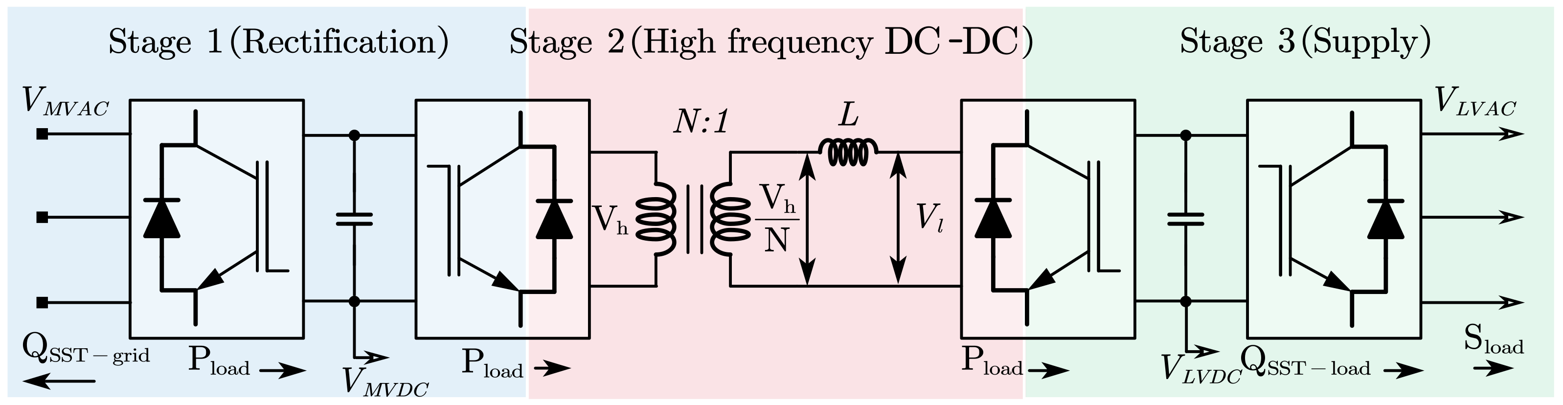
Figure 12.
Hybrid AC/DC distribution network configurations with SST: (a) two-stage completely isolated configuration, (b) two-stage partially isolated configuration, and (c) three-stage partially isolated configuration [269].
Figure 12.
Hybrid AC/DC distribution network configurations with SST: (a) two-stage completely isolated configuration, (b) two-stage partially isolated configuration, and (c) three-stage partially isolated configuration [269].

Figure 13.
Radial configuration with a three-stage SST [270].
Figure 13.
Radial configuration with a three-stage SST [270].

Figure 14.
Hybrid AC/DC meshed network configuration with SST and LVDC line [271].
Figure 14.
Hybrid AC/DC meshed network configuration with SST and LVDC line [271].
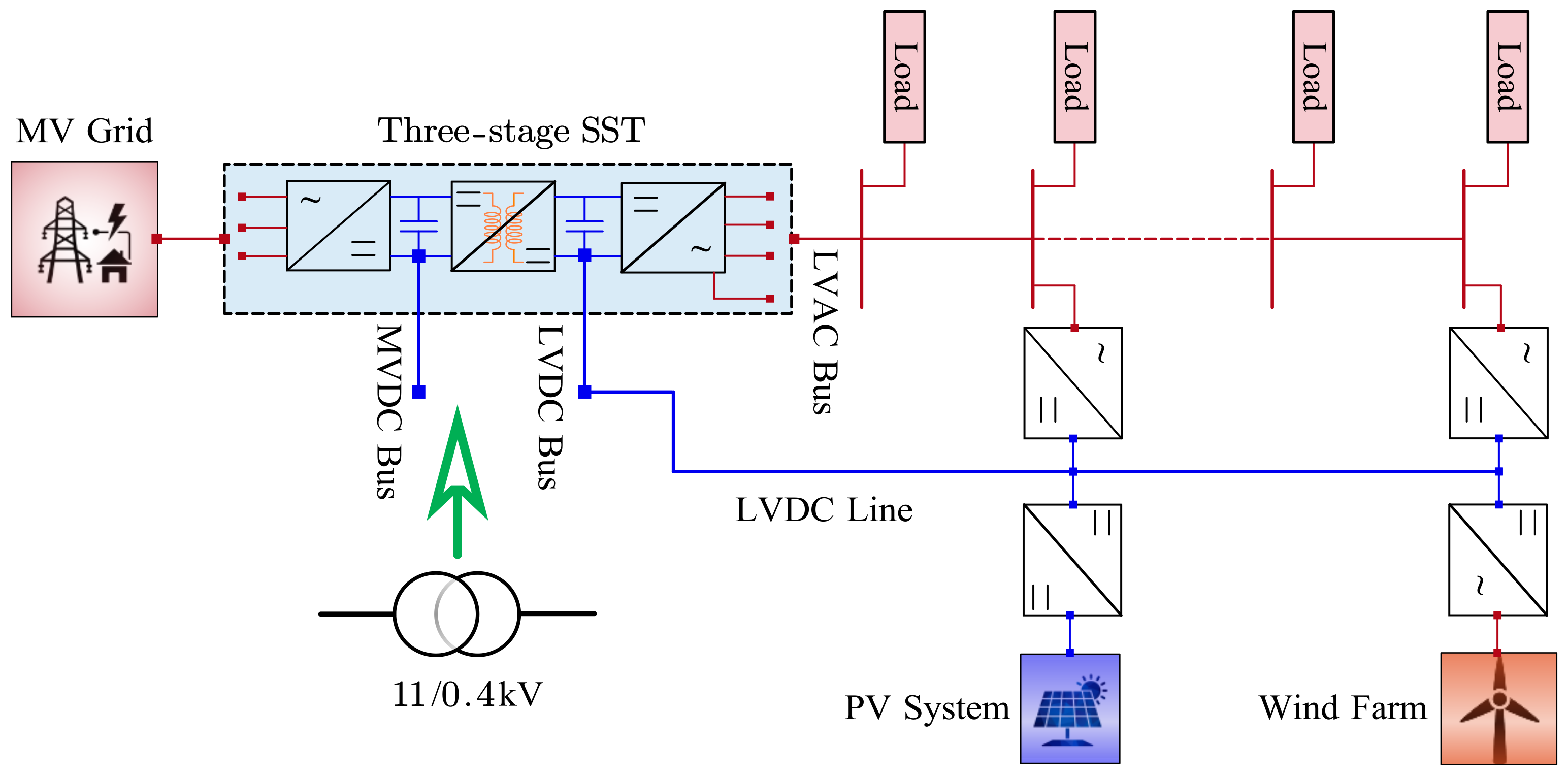
Figure 15.
Meshed DC network configuration with SST and tie line [273].
Figure 15.
Meshed DC network configuration with SST and tie line [273].

Figure 16.
Hybrid AC/DC network configuration with two SSTs with standard passive transformer (T/F) [274].
Figure 16.
Hybrid AC/DC network configuration with two SSTs with standard passive transformer (T/F) [274].
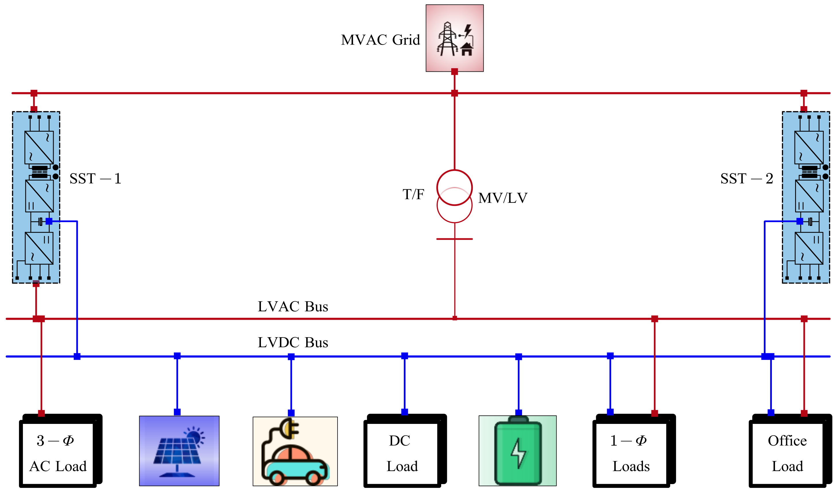
Figure 17.
Present and future of power system [268].
Figure 17.
Present and future of power system [268].
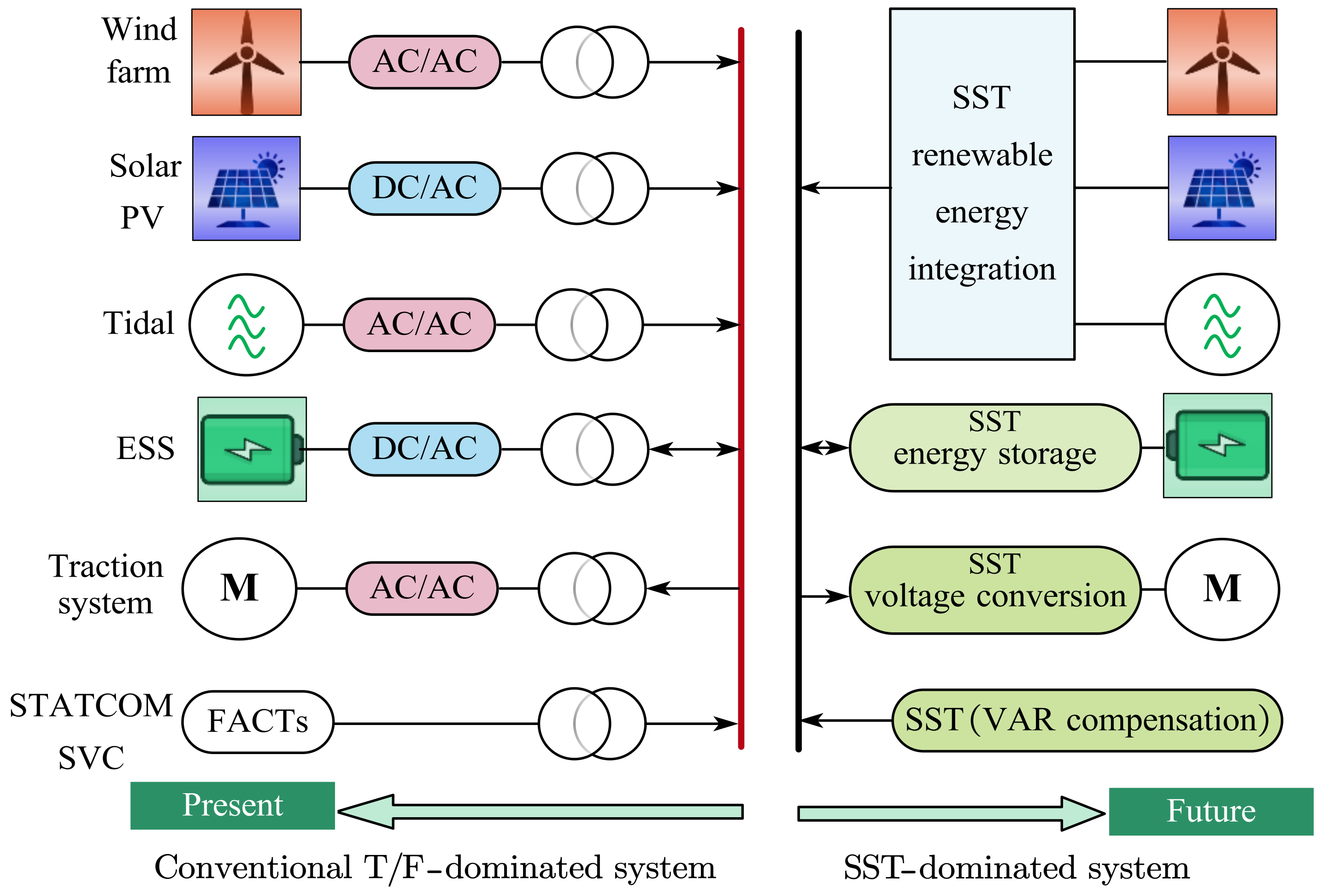

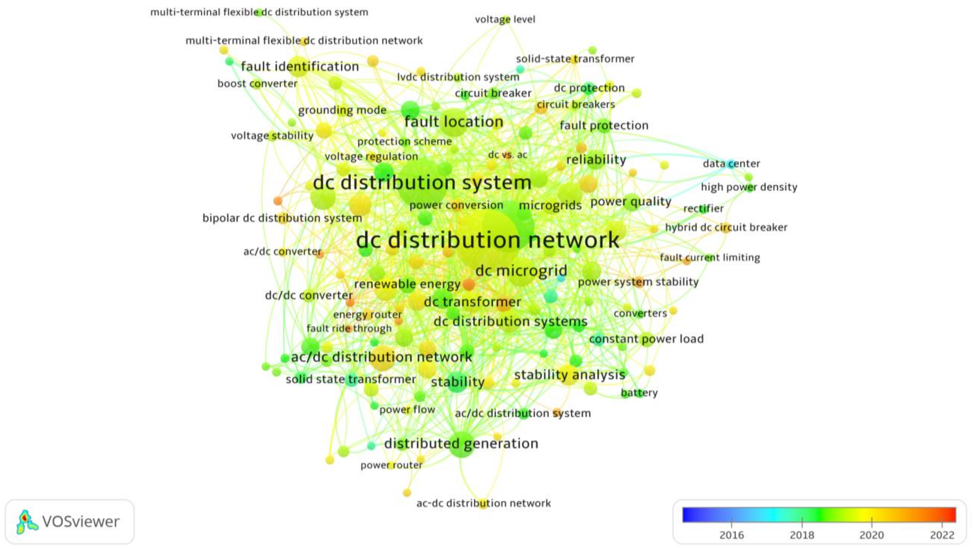
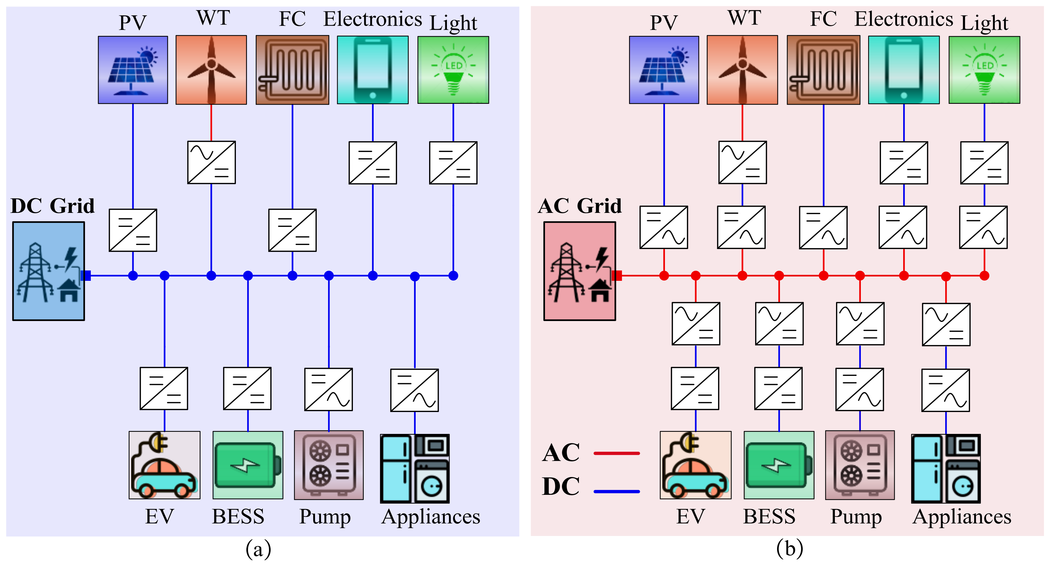
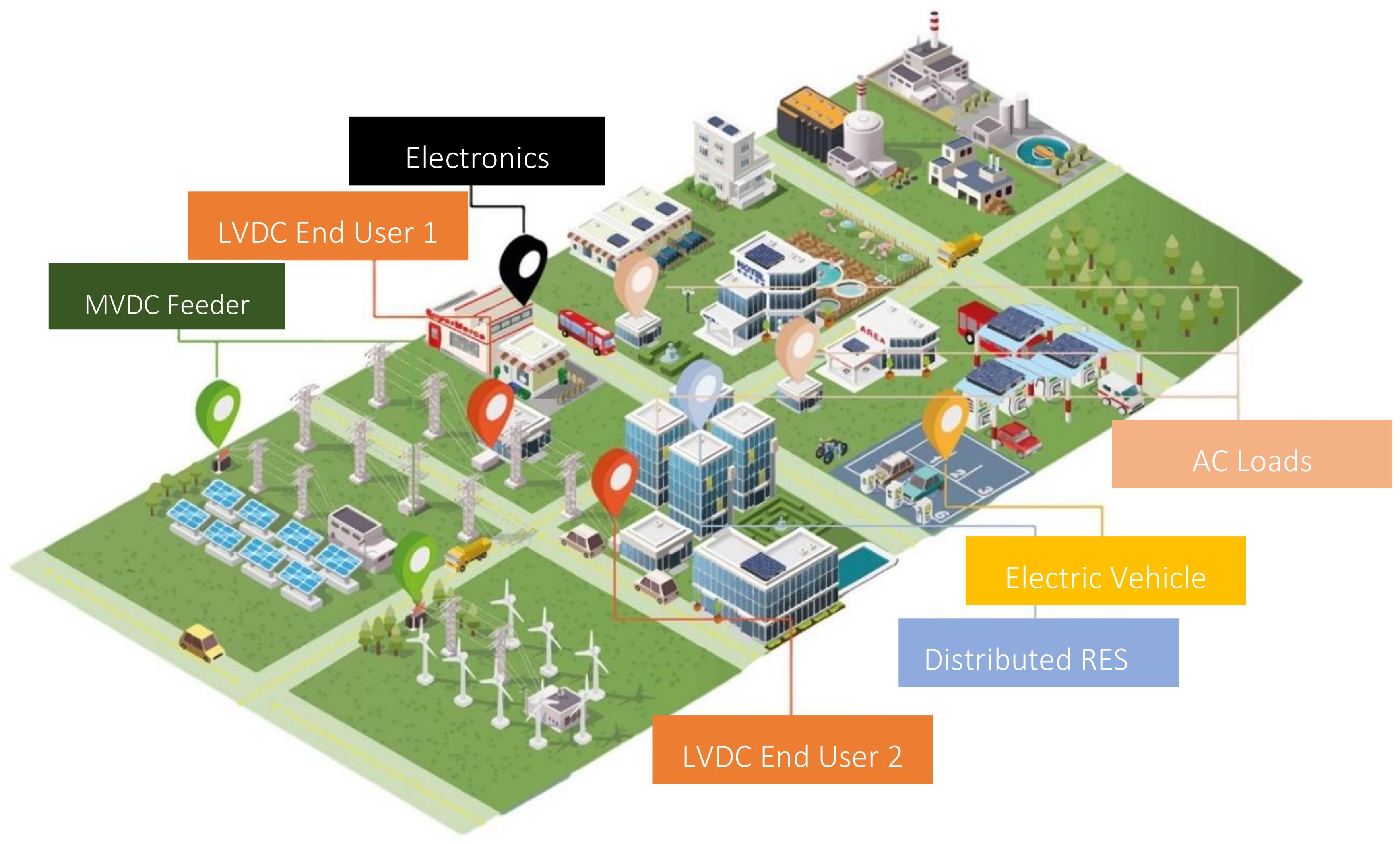
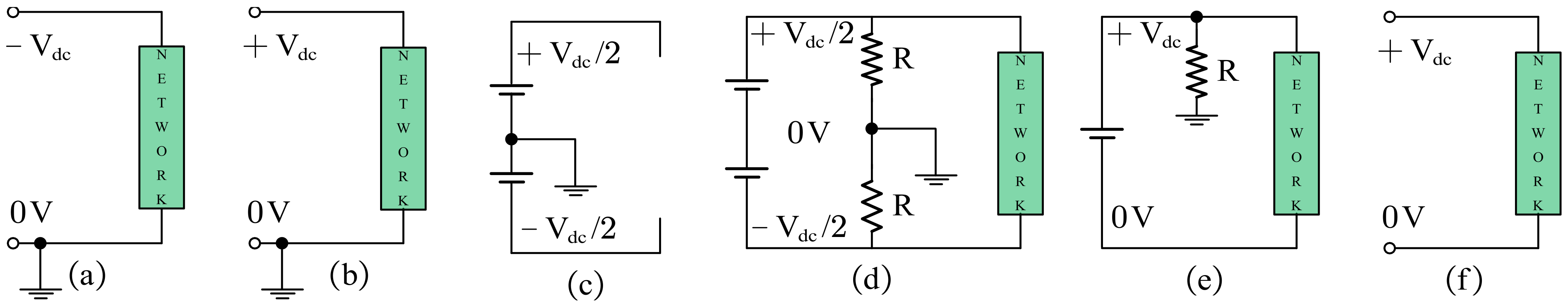
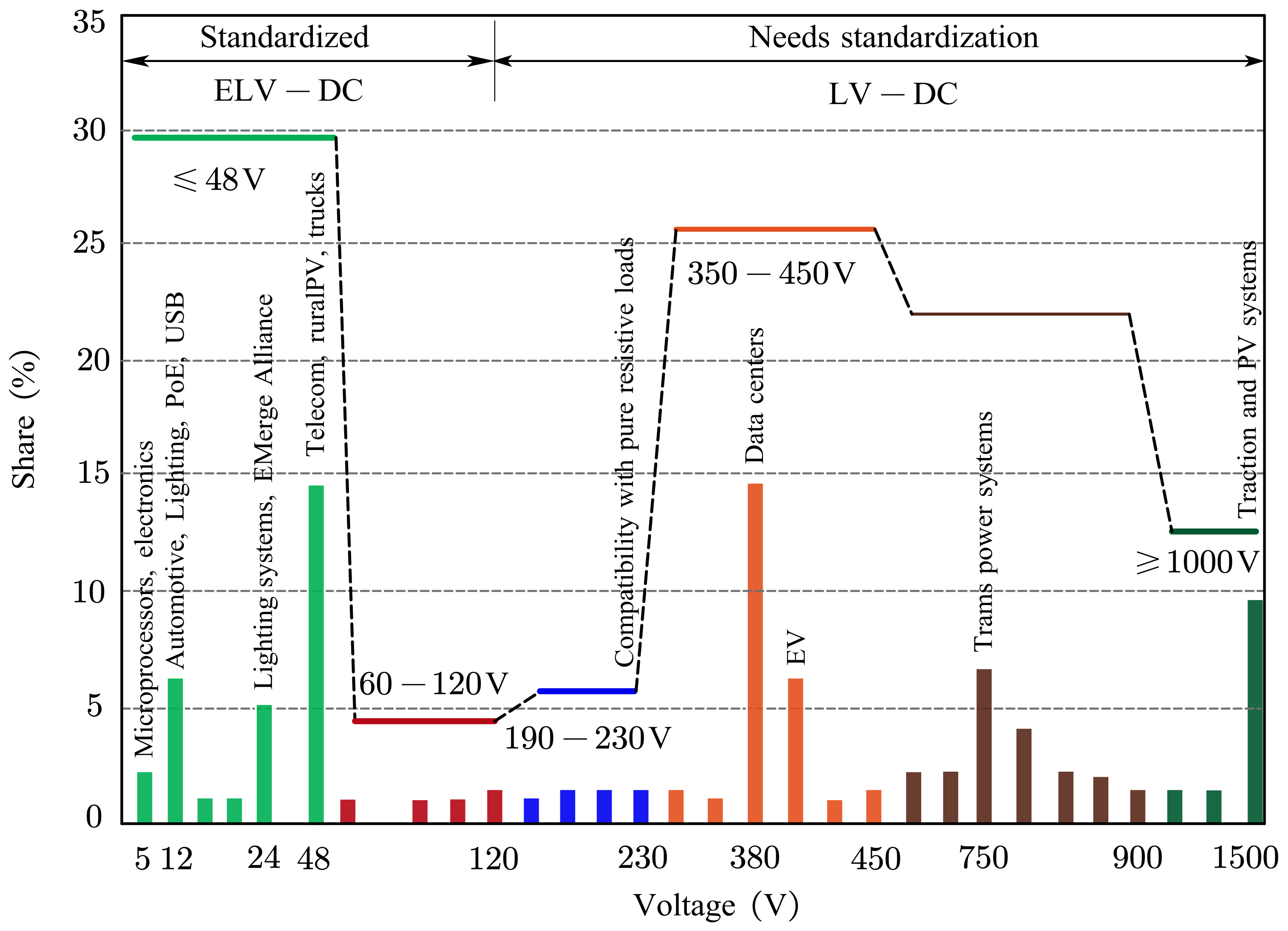
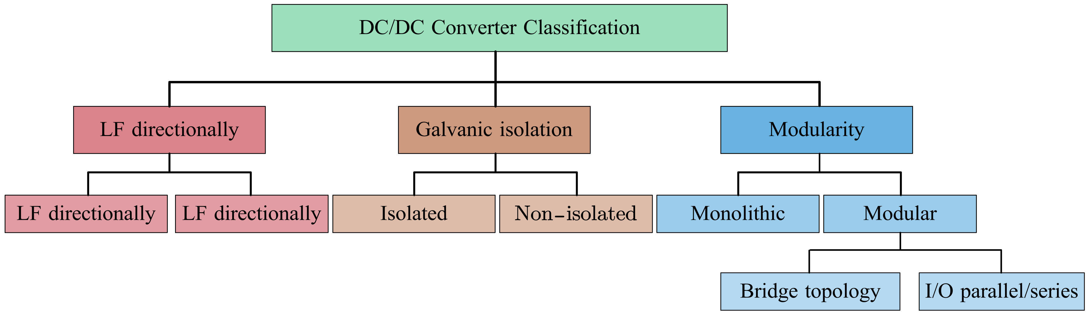
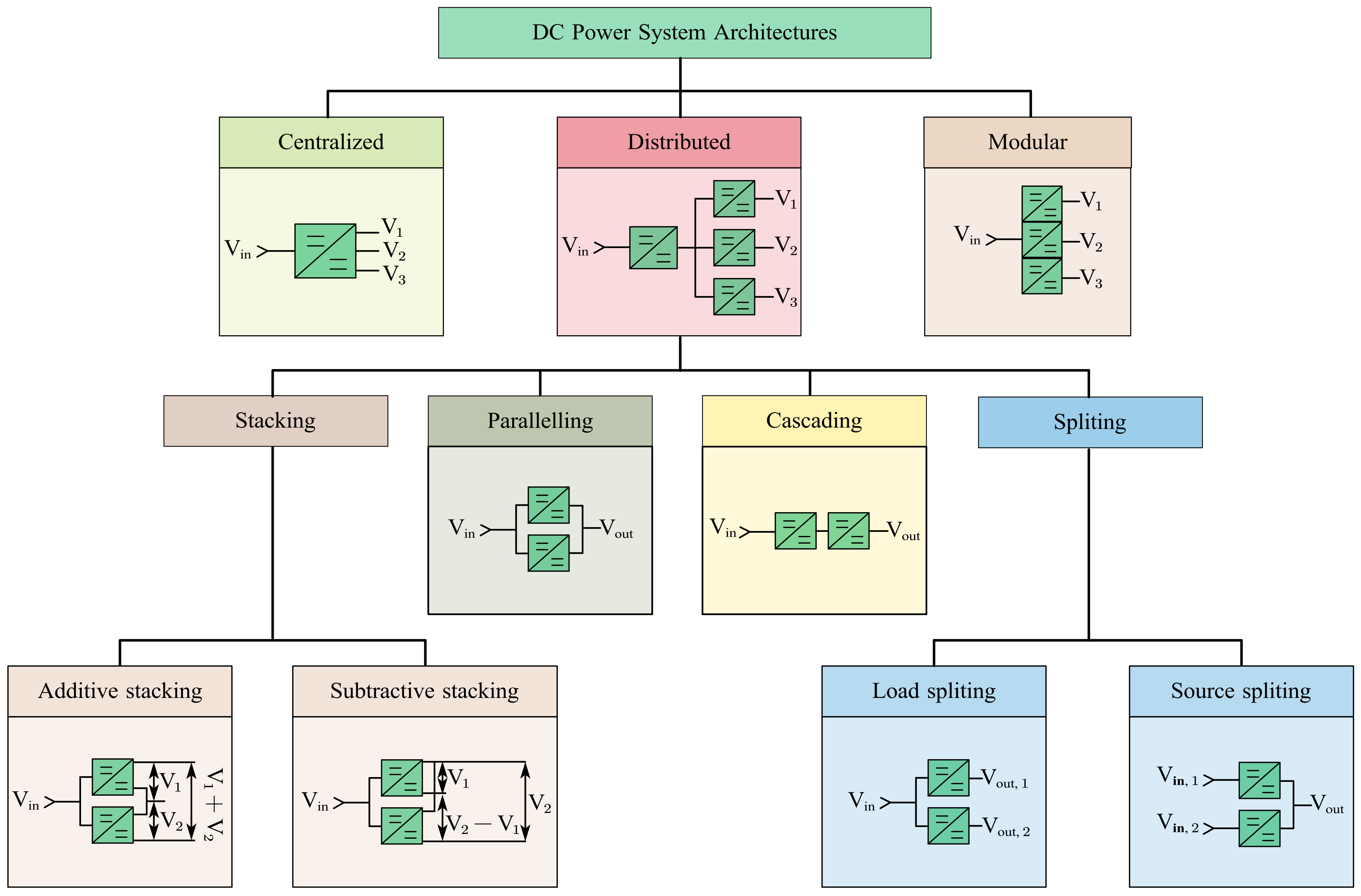
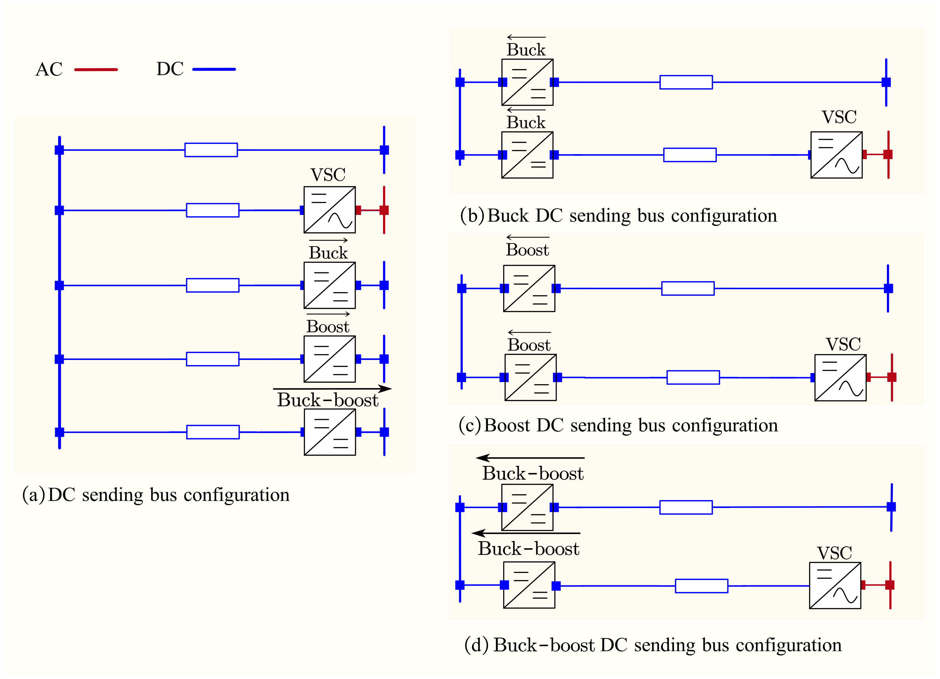
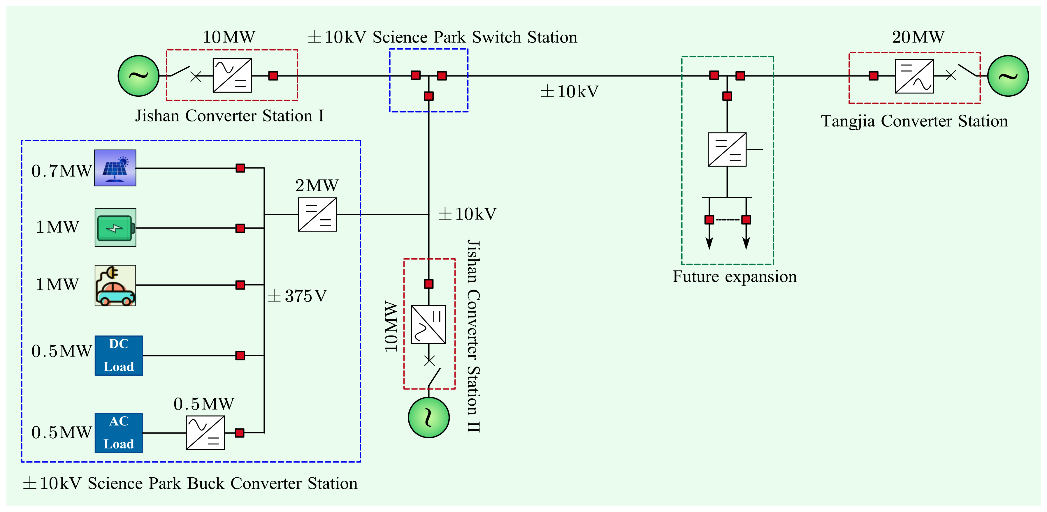
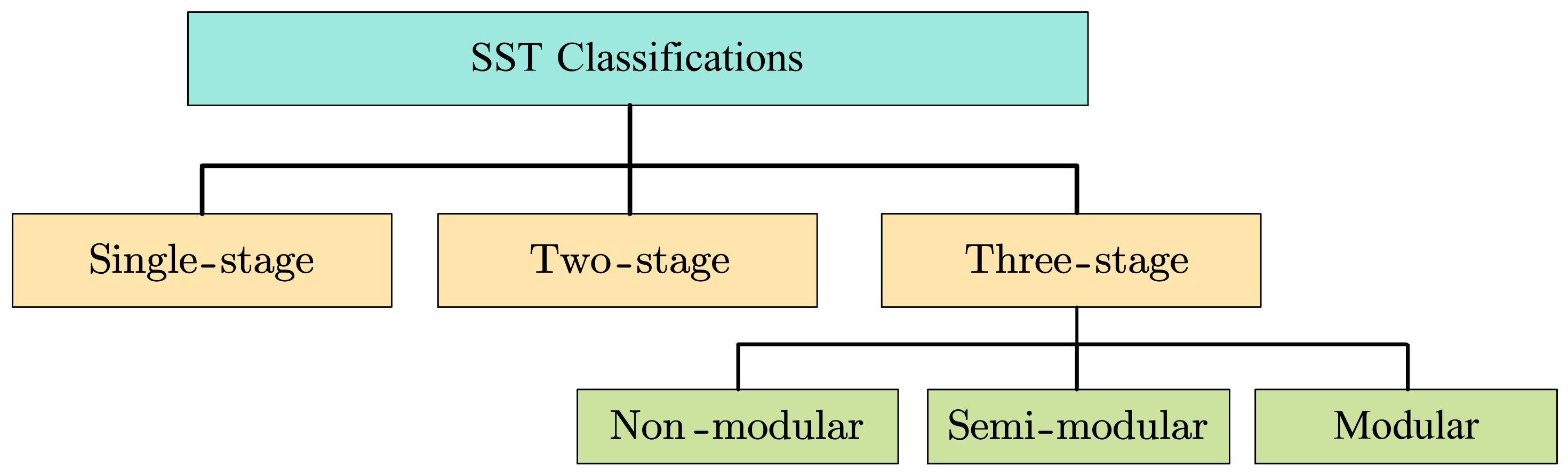
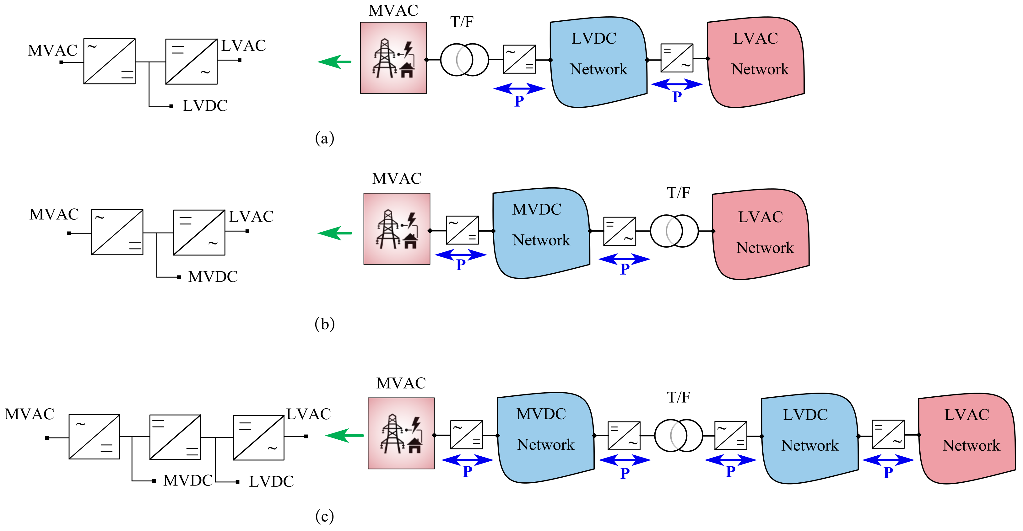
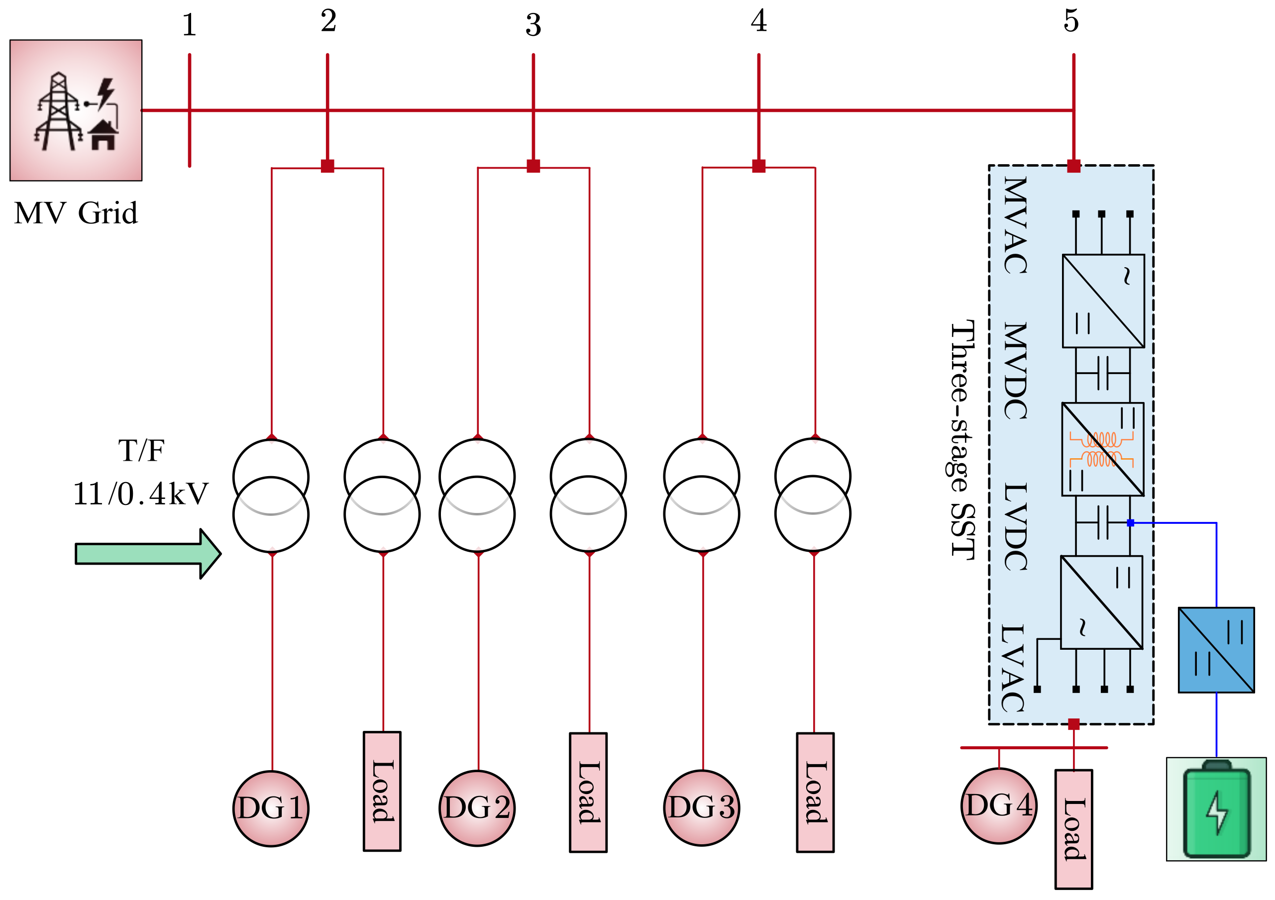
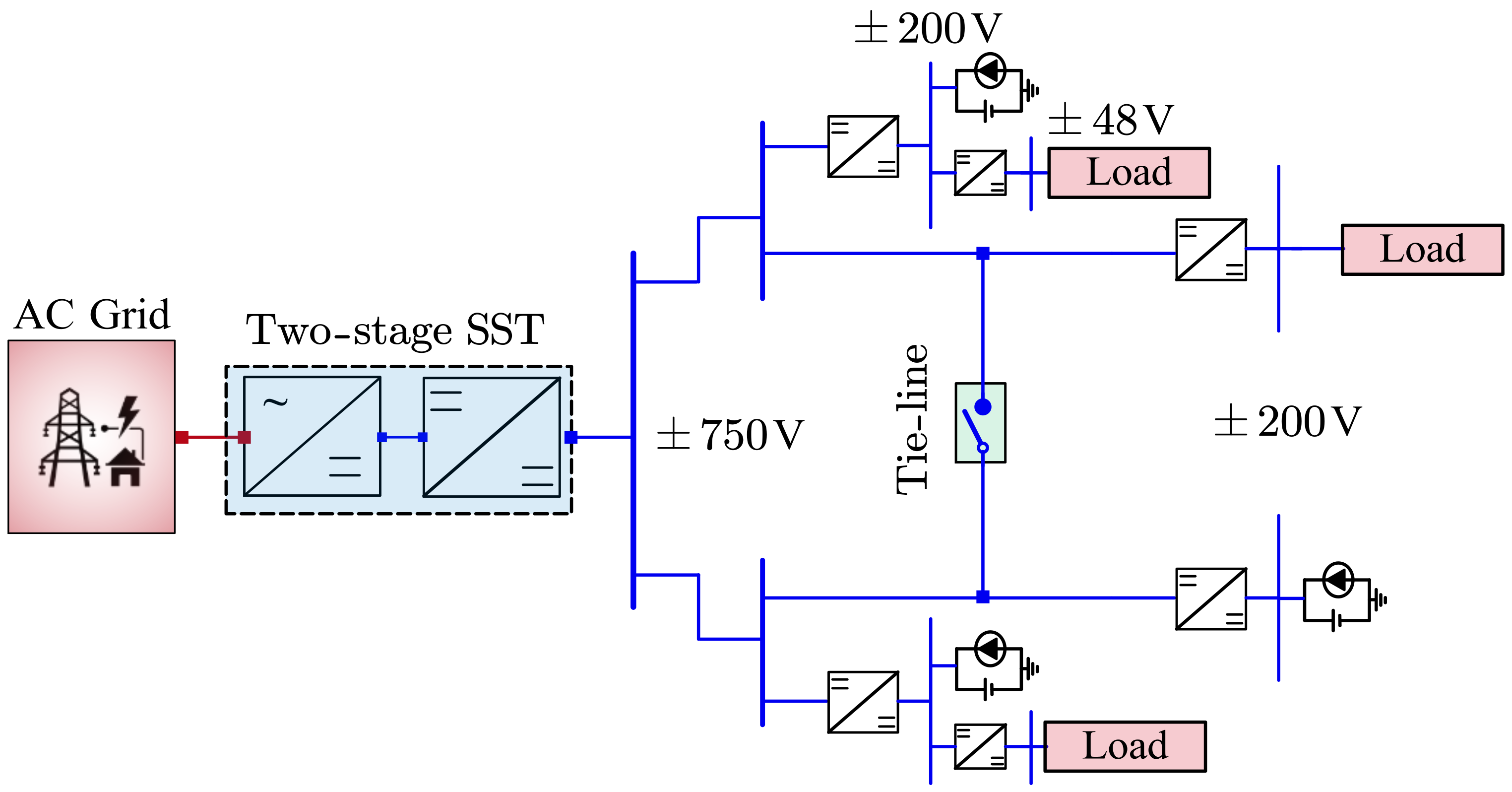
Table 1.
Overview of the bibliometric analysis based on authors’ keywords.
| Cluster | Main Area | Links | Occurrences | Related Keywords |
|---|---|---|---|---|
| 1 | Energy storage | 27 | 20 | Efficiency, renewable energy sources, battery, power flow, DG, EV |
| 2 | AC/DC distribution system | 15 | 42 | Load flow, EV, DG, VSC, power router, AC/DC converters |
| 3 | Constant power loads | 14 | 16 | DC transformer, DC/DC converters, energy storage, stability analysis |
| 4 | Modular multilevel converter | 26 | 33 | Stability, DG, protection, DC loads, AC/DC converter, DC/DC converter |
| 5 | Load modeling | 22 | 10 | Load flow, stability, voltage regulation, network topology, optimal power flow, hybrid AC/DC network |
| 6 | DC distribution network | 66 | 236 | Energy storage, load flow, stability analysis, protection, voltage levels, network topology, human safety, RES, EVs, DC loads, efficiency |
| 7 | DC protection | 12 | 11 | Fault detection, fault location, fault identification, DC circuit breaker |
| 8 | Stability | 23 | 30 | Constant power load, DC/DC converters, EVs, flexible DC distribution |
| 9 | DC microgrids | 39 | 33 | Power quality, protection, distributed generation, energy management, LVDC, solid-state transformer (SST), renewable energy sources |
| 10 | Distributed generation | 31 | 44 | Renewable energy, smart grid, power system planning, DC grid, SST |
| 11 | Solid state transformer (SST) | 8 | 7 | AC and DC distribution network, AC-DC hybrid distribution network, power quality, reliability |
| 12 | Power flow | 6 | 6 | Distributed generation, constant power loads, RESs |
| 13 | DC distribution | 72 | 160 | Power flow, DC loads, solid state transformer, network topology, constant power loads, DC/DC converters |
Table 2.
The main features of the literature on DC LF methods.
| Reference | PF Method | Network Topology | DC/DC Interconnections | Existence and Uniqueness of the PF Solution | Iterative/ Non-Iterative |
|---|---|---|---|---|---|
| Ref. [113] | LA | R: ✓ M: ✓ BP: ✗ | ✗ | ✓ | iterative |
| Ref. [116] | SLA A-oHC | R: ✓ M: ✓ BP: ✗ R: ✓ M: ✓ BP: ✗ | ✗ ✗ | ✗ ✗ | iterative iterative |
| Ref. [114] | A-oHC | R: ✓ M: ✗ BP: ✗ | ✗ | ✗ | non-iterative |
| Ref. [111] | A-oHC Q-NR | R: ✓ M: ✓ BP: ✓ R: ✓ M: ✓ BP: ✓ | ✗ ✗ | ✗ ✗ | iterative iterative |
| Ref. [103] | NR | R: ✓ M: ✓ BP: ✗ | ✗ | ✗ | iterative |
| Ref. [109] | NR | R: ✓ M: ✓ BP: ✓ | ✗ | ✗ | iterative |
| Ref. [110] | NR | R: ✓ M: ✓ BP: ✗ | ✗ | ✓ | iterative |
| Ref. [104] | CIM | R: ✓ M: ✓ BP: ✗ | ✗ | ✓ | iterative |
| Ref. [105] | MM Z-bus EFM | R: ✓ M: ✓ BP: ✗ R: ✓ M: ✓ BP: ✗ R: ✓ M: ✓ BP: ✗ | ✗ ✗ ✗ | ✓ ✓ ✓ | iterative iterative non-iterative |
| Ref. [108] | BFS | R: ✓ M: ✗ BP: ✗ | ✗ | ✗ | iterative |
| Ref. [107] | BFS SA | R: ✓ M: ✓ BP: ✓ R: ✓ M: ✓ BP: ✓ | ✗ ✗ | ✗ ✓ | iterative iterative |
| Ref. [106] | SA TSE | R: ✓ M: ✓ BP: ✗ R: ✓ M: ✓ BP: ✗ | ✗ ✗ | ✗ ✗ | iterative iterative |
| Ref. [115] | TSE | R: ✓ M: ✓ BP: ✗ | ✗ | ✗ | non-iterative |
| Ref. [112] | UTM | R: ✓ M: ✗ BP: ✗ | ✗ | ✗ | iterative |
| Ref. [119] | FPI | R: ✓ M: ✓ BP: ✓ | ✗ | ✓ | iterative |
| Ref. [75] | LM | R: ✓ M: ✓ BP: ✗ | ✗ | ✓ | iterative |
| Ref. [117] | ILM | R: ✓ M: ✓ BP: ✗ | ✗ | ✓ | iterative |
| Ref. [118] | e-ILM | R: ✓ M: ✓ BP: ✗ | ✓ | ✓ | iterative |
| Ref. [120] | MANA | R: ✓ M: ✓ BP: ✗ | ✗ | ✓ | iterative |
| Ref. [121] | e-MANA | R: ✓ M: ✓ BP: ✗ | ✓ | ✓ | iterative |
R: radial, M: meshed, BP: bipolar, ✓: considered, ✗: not considered.
Table 3.
DC voltage standards.
| Volage Band | Voltage Level (Vdc) | Standard |
|---|---|---|
| SELV & PELV | 24 | [227] (Emerge Alliance (Occupied Space Std)) |
| 50 | [228] (IEEE 802.3 bt, 802.3 bu) | |
| 75 | [229] (EU LDV 2014/35/EU) | |
| 120 | [230] (Limit of SELV and PELV:IEC61140) | |
| LVDC | 240 | [231] (Power supply system for Telecom: YD/T 2378-2011) |
| 380 | [227] Emerge Alliance (Data/Telecom Std) | |
| 400 | [232] (Limit of Telecom DC Source ETSI EN 300 132-3-1) | |
| 400 | [233] (Earthing and bonding of 400 Vdc: ETSI EN 301 605) | |
| 400 | [234] (DC power feeding interface up to 400 Vdc: ITU-T L.1200) | |
| 1500 | [235] (Limit of LVDC: IEC60038) | |
| MVDC | 1.5 kV~100 kV | [236] (IEEE Std. 1709) |
| HVDC | 100 kV~800 kV | [237] (IEC 61975:2010) |
Table 4.
Summary of DC distribution systems implemented worldwide with their operating voltage levels.
Table 4.
Summary of DC distribution systems implemented worldwide with their operating voltage levels.
| Voltage Level | Country | Organization |
|---|---|---|
| 24 | USA [90,208] | Whole Foods Market, Berkeley; Sust. Resource Center; Alliance Center; PNC Bank, Fort Lauderdale; Fort Belvoir, Alexandria; AGU Building Washington DC; Bedrock Real Estate, Detroit |
| 200 | New Zealand [208,211] | Telecom NZ |
| 350 | France [208] | France Telecom |
| Sweden [208] | UPN AB | |
| 360 | Italy [253] | HYPERRIDE Demo 3 (Terni) |
| 380 Vdc | USA [90] | University of California San Diego; Purdue University; SAP; Intel Corporation; Standford University; IO; Duke Energy; Clustered Systems; NEXTEX; IBM; Validus (ABB); Syracuse University; Steel Orca; North America Telecom; Livingston and Haven, Charlotte; Fitness Center, Fort Bragg; Honda Warehouse Retrofit; Silver cloud Winery, Glen Ellen; Kirtland Air Force Base Albuquerque |
| Canada [90,208] | Canada Telecom Operator | |
| Japan [10] | The Fukuoka Smart House | |
| Denmark [10] | Aalborg University | |
| France [194,208] | France Telecom | |
| Swiss [208] | Green.CH, ABB | |
| India [208] | IBM | |
| Taiwan [94] | Taiwan IT | |
| Singapore [208] | IBM | |
| China [208] | China Mobile | |
| New Zealand [208] | Telecom NZ | |
| 400 | USA [90,208] | Intel Corporation |
| 550 | USA [90,208] | Validus (ABB) |
| 240/380 | China [208] | China Telecom |
| 350/380 | Sweden [208] | Netpower Labs AB |
| 380/400 | Japan [10,208] | NTT Group |
| 700–750 | Switzerland [92] | HYPERRIDE Demo 1 (Lausanne, CH) |
| 380–1000 | Germany [92] | HYPERRIDE Demo 2 (Aachen, DE) |
Disclaimer/Publisher’s Note: The statements, opinions and data contained in all publications are solely those of the individual author(s) and contributor(s) and not of MDPI and/or the editor(s). MDPI and/or the editor(s) disclaim responsibility for any injury to people or property resulting from any ideas, methods, instructions or products referred to in the content. |
© 2024 by the authors. Licensee MDPI, Basel, Switzerland. This article is an open access article distributed under the terms and conditions of the Creative Commons Attribution (CC BY) license (https://creativecommons.org/licenses/by/4.0/).
Share and Cite
MDPI and ACS Style
Javid, Z.; Kocar, I.; Holderbaum, W.; Karaagac, U. Future Distribution Networks: A Review. Energies 2024, 17, 1822. https://doi.org/10.3390/en17081822
AMA Style
Javid Z, Kocar I, Holderbaum W, Karaagac U. Future Distribution Networks: A Review. Energies. 2024; 17(8):1822. https://doi.org/10.3390/en17081822
Chicago/Turabian StyleJavid, Zahid, Ilhan Kocar, William Holderbaum, and Ulas Karaagac. 2024. "Future Distribution Networks: A Review" Energies 17, no. 8: 1822. https://doi.org/10.3390/en17081822
Note that from the first issue of 2016, this journal uses article numbers instead of page numbers. See further details here.