Abstract
This work deals with doubly fed induction generator (DFIG) modeling and stability when connected to weak AC grids. A detailed state-space model that includes the phase-locked loop (PLL) is developed. This work aims to determine the influence of the network’s strength on DFIG stability through the short-circuit ratio (SCR). The critical values of the proportional control parameters of the grid-side and rotor-side converters (RSC and GSC), as well as PLL, which make the system unstable, are calculated for different SCR values. Finally, PSCAD/EMTDC dynamic simulations are used to validate the critical control parameters obtained by studying the eigenvalues of the DFIG state-space model regarding system stability.
1. Introduction
Doubly-fed induction generators (DFIGs) are one of the leading technologies used in wind generators. Unfortunately, the interaction between weak grids and DFIGs can cause stability problems. The instability mechanism in wind turbine generators differs entirely from traditional sub-synchronous resonance in steam turbine generators [1]. DFIG instability is probably related to a new type of instabilities caused by equipment with power electronics technology recently described in the literature [2,3]. Low-frequency oscillations characterize these instabilities. Frequency domain [4,5,6] and state-space methods [7,8,9,10,11,12,13,14,15,16,17,18] are useful and widely used tools for instability phenomena analysis when DFIGs are connected to weak grids, among other applications. It is known that state-space methods have a large computational burden; power system characterization by means of impedance and frequency-based methods requires fewer computational resources. Moreover, when a circuit modification occurs, the change only affects one part of the circuit; on the contrary, state-space analysis requires a complete reformulation. However, the main disadvantage is that stability is more complicated to determine than checking the positivity of the real part of the eigenvalues. This work uses the state-space method to investigate the impact of the SCR—short-circuit ratio—on DFIG stability.
The literature contains a large number of DFIG models with different characteristics, such as phase-locked loop (PLL) absence or presence, outer control loops, mechanical equations, etc., making it difficult to compare the models. The comparison must also consider the DFIG connection to a weak grid or a series-compensated line. Table 1 summarizes the main characteristics of the models in the literature. Some studies do not include the PLL [7,8,9,10,11,14,15,16,18,19,20] or use approximations that reduce the order of state-space equations [9,10,11,12,13,19,20]. Other references propose the study of DFIG stability with a series-compensated line [7,8,14,15,16,17,18,20]. This problem is more complex than the weak grid examined in this work. An explanation for the excessive use of approximations in DFIG state-space modeling studies is that they focus on finding low-frequency instabilities caused by the mechanical part. An essential contribution of this work is demonstrating that the current loop controls of the RSC, GSC, and the PLL can also cause low-frequency instabilities. Therefore, rigorous modeling of these elements is essential. To illustrate the errors resulting from approximations, the case of the approximation of the DC capacitor by a voltage source, which is widely used in the literature, is examined. Few references [16,19,20] carry out a detailed analysis of DFIG stability using different parameters; the authors are not aware of any such studies, including those analyzing the impact of the SCR. However, several works have investigated its influence on VSC-HVDC converter stability [21,22,23].

Table 1.
Comparison of models.
The proposed model has 18 state variables. For simplicity, the mechanical model is not included, nor are three of the four outer control loops. Therefore, a complete DFIG model without simplifications should have around 24 state variables. Looking at Table 1, it appears that many models do not take the PLL into account. In this paper, it is shown that the PLL is critical for the stability of the DFIG. Taking into account this fact and the number of state variables of each reference, it is observed that only [17] can be considered a complete model without approximations. In [17], a DFIG with a series-compensated line is studied. As a summary of the bibliographic study in Table 1, it is observed that there is no study without approximations of the DFIG in weak grids in the literature.
Compared to DFIG studies using the state-space method, the contributions of this work are fourfold:
- A detailed description of the state-space model, which captures the influence of the PLL on GSC and RSC voltages (see Table 1);
- A study of the influence of the SCR on the critical values (stability boundary) of the control parameters, which make the DFIG unstable for different DFIG power values;
- The validation of the instability predictions of the state-space model by hundreds of PSCAD simulations, providing excellent results;
- A study of the approximation of the DC capacitor by an ideal voltage source to show that the approximations in the literature can lead to incorrect predictions.
2. DFIG Model
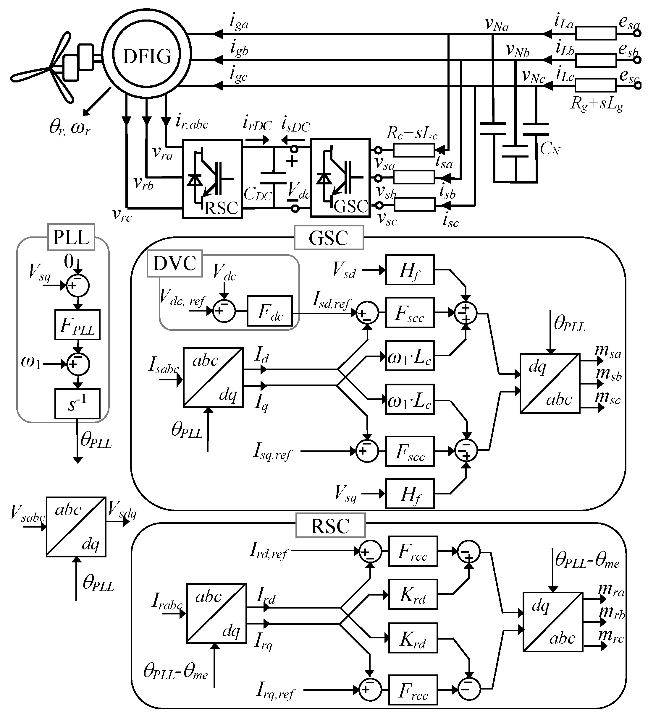
The DFIG model proposed in this work is shown in Figure 1. An important simplification consists of excluding the outer controls for P and Q, because PLL and current loop dynamics are faster than those outer loops. This is because the set points of P and Q (the active and the reactive power) are obtained using wind speed data and are based on maximum power point tracking curves, where the optimal value is found for each mechanical speed [7,15,18]. Moreover, the non-inclusion of the dynamics of the mechanical part makes the study more manageable. The investigation focuses on DFIG stability when it is connected to a weak grid and does not address the problem of series-compensated lines, which is exciting but much more complex. Figure 1 shows capacitors, CN, at the induction generator terminals. They are fictitious, with a very high impedance (a very small capacitor), so that the current absorbed by them is negligible. This is convenient for avoiding an inductive node, i.e., a relationship between state variables (currents in the inductors), one of which is linearly dependent on the others. The item “inductive node eliminated” in Table 1 shows the references addressing this linear dependency problem. A significant problem in the literature is considering that RSC and GSC control is carried out in the dq-converter reference, while dq-grid is used for the network and induction generator equations. The change in reference results in the angle θPLL appearing in the equations of the converter voltages. The item “Correct dependence of vs. and vr of θPLL” in Table 1 shows that this dependence is not formulated correctly in the literature.
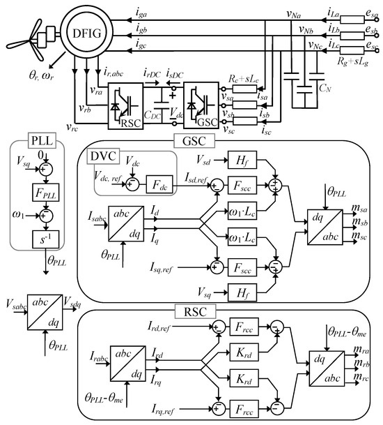
Figure 1.
DFIG equivalent circuit and controls.
Grid-connected DFIG stability is studied using the proposed state-space model. Both the model and the stability study are validated by PSCAD/EMTDC simulation (PSCAD X4 Version 4.5.0.0). These PSCAD/EMTDC simulations are made with a custom DFIG model, developed ad hoc and exhaustively validated in [24].
2.1. Induction Machine Model
The equations of the induction generator in terms of dq-variables (Park variables) [25,26], where vNd and vNq are the stator voltages, igd and igq are the stator currents, vrd and vrq are the rotor voltages, and ird and irq are the rotor currents, are as follows:
where Ls = Lsd + M and Lr = Lrd + M, with Lsd and Lrd being the stator and rotor leakage inductances, M being the magnetizing inductance, ω1 = 2πf1 being the fundamental angular frequency of the grid, and s being the Laplace operator. The slip, g, is
where the mechanical speed in electrical degrees is ωme, considering the machine pairs of poles. It is important to note that, in (1), the rotor currents have an outgoing direction from the generator, which is different from usual [25,26]. This change is made so that the rotor current matches the direction of the currents in the RSC equations. Rewriting (1) in matrix form, we have
where
and the induction machine equations in state equation form are
where
2.2. AC Grid and Stator Relations
The small-signal voltage line equation in the dq-domain from Figure 1 is
where ω1 = 2πf1 is the grid fundamental angular frequency, vNdq = (vNd vNq)T is the stator induction generator voltage, edq = (ed eq)T is the grid voltage, and iLdq = (iLd iLq)T is the line current.
The connection between the stator induction generator and the GSC is the Rc-Lc filter, and its equations are
The introduction of the dummy capacitor CN avoids a binding between the current generator igdq, the GSC current isdq, and the line current iLdq. The capacitor equations are
2.3. AC–DC Converter Relations
The modulation function mxdq = (mxd mxq)T links the VSC output voltage vxdq in the GSC (x = s) or the GSC (x = r) and the DC voltage Vdc0 as
Considering an ideal VSC and ignoring the homopolar component, the VSC instantaneous power balance between the DC and AC sides imposes the next relation between the AC current idq and the DC current idc:
The sum of currents in the DC capacitor results in the equation
where
with mxdq being the modulation function of the GSC (x = s) or the RSC (x = r).
2.4. Stator and Rotor CC Loop Connections
The CC loop control law in the GSC in the dq-domain using the sign convention in [27] is
where vcsdq,r = (vcsd,r vcsq,r)T, icsdq,r = (icsd,r icsq,r)T are the voltage and current references, and Fscc(s) = ksp + ksi/s, with ksp and ksi being the proportional and integral gains of the inner CC of the GSC. Variables with super index c are in the converter reference.
In the RSC, the current reference depends on the wind speed and the power that can be extracted [7,15,18]. The maximum power curve in front of the rotor speed is information given by the manufacturer. The outer rotor current control loop relies on wind dynamics and is assumed constant because its dynamic response is much slower compared to the other control loops.
The control law of the inner CC loop in the RSC results in
where Frcc(s) = krp + kri/s, with krp and kri being the proportional and integral gains of the inner rotor CC in the RSC. The decoupling gain Krd is
2.5. Outer Control Loop Relations
The direct-voltage control (DVC) law is considered as
where Fdc(s) = kDCp + kDCi/s, with kDCp and kDCi being the DVC proportional and integral gains.
2.6. PLL Rotor and Stator Relations
The rotor variables are subject to ϑr = ϑs − ϑme. An encoder is needed to determine the rotor position in electrical degrees, ϑme. If ϑme is accurate enough, its effect on the PLL is insignificant. Therefore, the rotor variables depend on ϑs, similar to the stator variables.
The objective of the PLL is to cancel the term vq in the converter reference, so we have
where FPLL(s) = kPLLp + kPLLi/s, with kPLLp and kPLLi being the PLL control proportional and integral gains, and θ being the angle of the converter reference with respect to the grid reference. We define the state-space variable xθ as
and the PLL equation is expressed in the state-space model as
The relationship between the converter reference (GSC or RSC) with respect to the grid reference in terms of the stator (x = s) or rotor (x = r) currents, ixdq, is
Variables with super index c are in the RSC or GSC reference. Otherwise, the absence of this super index indicates a grid reference. The relationship of the grid voltages as a function of the converter voltages is
Considering these changes in reference, the equations of the RSC voltages (18) in the grid reference are
where the new state-space variables, γrd and γrq, in the converter reference are
The calculation takes into account that
and similar to the GSC, we have
Grid reference GSC voltages (17) are
where the new state-space variables, xdc1, xdc2, and γsq, in the converter reference are
3. State-Space Model
The differential equations of the DFIG state-space model result in
Equations (32)–(35) and (38) are in the grid reference and Equations (36), (37) and (39) are in the RSC and GSC references.
To obtain the correct linearized state-space equation, it must be highlighted that the RSC voltages, vrdq, depend on vrdq = vrdq(ird, irq, γrd, γrq, vdc, θ) and that the GSC voltages depend on vsdq = vsdq(isd, isq, γsq, xdc1, xdc2, vdc, θ), similar to the modulation functions, msdq and mrdq, in (38).
4. Eigenvalue Analysis of DFIG
DFIG dynamics are described with a nonlinear system (32)–(39) as
Linearizing around an equilibrium point results in
where A is the Jacobian matrix of f(x) at the equilibrium point.
The eigenvalues of A
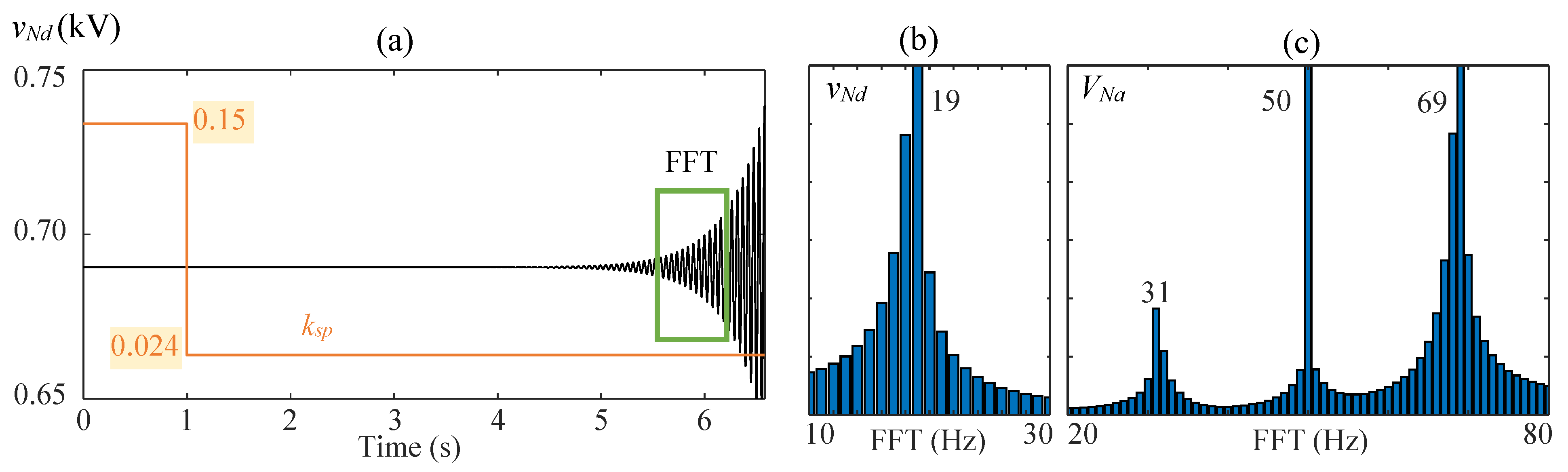
determine the stability of the linearized system. Figure 2a presents the unstable voltage transient at the converter terminals, vNd, if the GSC proportional gain, ksp, changes from 0.15 to 0.024. DFIG parameter values are shown in Table 2. Induction generator data were extracted from [28]. The turn ratio of the stator winding to the rotor winding was changed to 1 for simplicity. In Figure 2, the slip of the induction generator is g = +0.3, and the weak grid has a short-circuit ratio of 1.5 (Rg = 0.0106 Ω and Lg = 0.6735 mH). The data corresponding to this case are given in Table 3. Figure 2b,c shows the frequency analysis of the unstable transient in Figure 2a. Figure 2b,c show one and two frequency peaks, respectively. Figure 2b peaks at 19 Hz, and Figure 2c peaks at 69 and 31 Hz. This is usual, since an unstable eigenvalue of the state equation in dq-real variables, x = + a + jω, indicates a frequency oscillation of fosc = ω/(2π) in dq variables. By converting the voltage from dq variables to abc variables with the Park transformation, which rotates with the pulsation ω1 = 2πf1, two frequency peaks, f+ = fosc + f1 and f− = fosc − f1, are obtained.
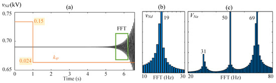
Figure 2.
Time (a) and frequency domain (b,c) stability study. The value ksp is changed from 0.15 to 0.024.
Table 2.
GSC, RSC, and Induction Generator Parameters.
Table 3.
DFIG steady-state data for different slips.
5. SCR Influence on DFIG Stability
The influence of the SCR (i.e., the quotient between the grid short-circuit power and the DFIG assigned power [22]) and the slip values as a characterization of the power conditions on DFIG stability is analyzed using an exhaustive and detailed numerical comparison between the results of the state-space model (see Section 2 and Section 3) and the PSCAD/EMTDC DFIG model in Figure 1. In particular, the maximum and minimum critical values of the GSC, RSC, and PLL proportional gains, which cause DFIG instability for different SCRs, slips, and an Xg/Rg ratio equal to 20, are assessed, and their instability frequencies are calculated and analyzed. Table 2 and Table 3 show the values of the DFIG model in Figure 1 and the DFIG steady-state operating points for three different power conditions (isq and igq are not included because they are 0). In the analyzed cases, the voltage at the DFIG terminals is guaranteed equal to 690 V; if necessary, a modification of the grid voltage is applied.
Other DFIG parameters, such as the DC voltage control loop proportional gain kDCp, were investigated but not included because their influence on stability is insignificant.
The feedforward voltage filter of the DFIG model in Figure 1 is also not included in the study because its inclusion makes the system more unstable.
Three different cases are presented to analyze the influence of the SCR on the maximum and minimum critical values of the GSC, RSC, and PLL proportional gains:
5.1. SCR Influence on the Extremum Critical Values of the Proportional Gains
5.1.1. Case #1
SCR influence on the extremum critical values (stability boundary) of the GSC (ksp), RSC (krp), and PLL (kPLLp) proportional gains, which cause DFIG instability, is studied. These values are calculated from the state-space model (42) in Section 2 and Section 3 and validated by PSCAD/EMTDC simulation. The results in per-unit values, i.e., αcc (pu) = ksp/ksp,Table 2, βcc (pu) = krp/krp,Table 2, and γcc (pu) = kPLLp/kPLLp,Table 2, are given in Figure 3 for different SCRs and three slips. The study range of αcc, βcc, and γcc is from 1000 to 0.001. The broken lines and the diamond dots represent the maximum critical values calculated with (42) and by PSCAD/EMTDC simulation, respectively. In contrast, the solid lines and the triangle dots represent the minimum critical values. The following conclusions are obtained from the study:
- Only the maximum critical values of the GSC proportional gain exist, which causes DFIG instability for very low SCR values and the slip value g = −0.3 (i.e., high DFIG power generation). For other conditions and other GSC and RSC proportional gains, no maximum critical value causes instability. The studied values of αcc and βcc are less than 1000.
- The lower the SCR, the higher the minimum values for critical GSC and PLL proportional gains.
- The lower the SCR, the lower the minimum value for critical RSC proportional gain. Hence, the highest minimum critical value is obtained with an infinite SCR and only depends on the slip (i.e., it has no dependence on the grid impedance).
- The most critical values of the RSC proportional gain occur when the DFIG is fed by strong grids (i.e., by grids with SCR = ∞). These values are βcc (pu) = 0.634, 0.523, and 0.415 for g = −0.3, 0, and 0.3, respectively.
- DFIG instabilities are mainly caused by the minimum critical values of the proportional gains, and these instabilities are related to oscillatory phenomena at low frequencies, which are among the most common power system instabilities in the literature [1,2,3].
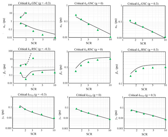
Figure 3.
Time critical stator, rotor, and PLL proportional gain for Case #1. Continuous lines: State-space minimum critical proportional gain predictions. Broken lines: State-space maximum critical proportional gain predictions. Triangle dots and diamond dots: PSCAD/EMTDC simulations.
Figure 3.
Time critical stator, rotor, and PLL proportional gain for Case #1. Continuous lines: State-space minimum critical proportional gain predictions. Broken lines: State-space maximum critical proportional gain predictions. Triangle dots and diamond dots: PSCAD/EMTDC simulations.
Note that the small differences between MATLAB (R2022a) and PSCAD results in Figure 3 are due to the unstable PSCAD points, which correspond to cases observed before 6 s of simulation after the change in the value of the proportional gain under study. If the simulation time is increased, the differences between MATLAB and PSCAD results become smaller.
5.1.2. Cases #2 and #3
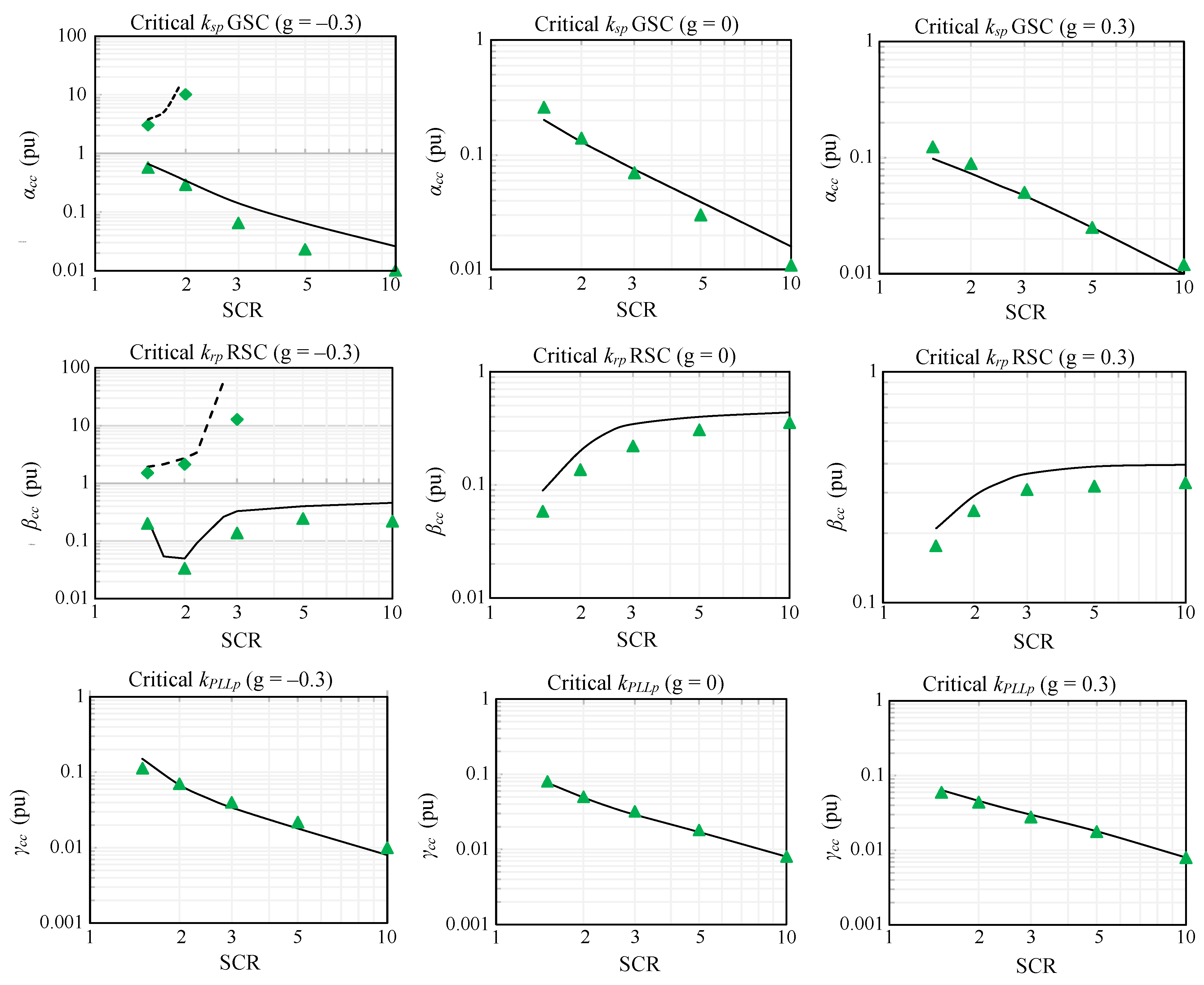
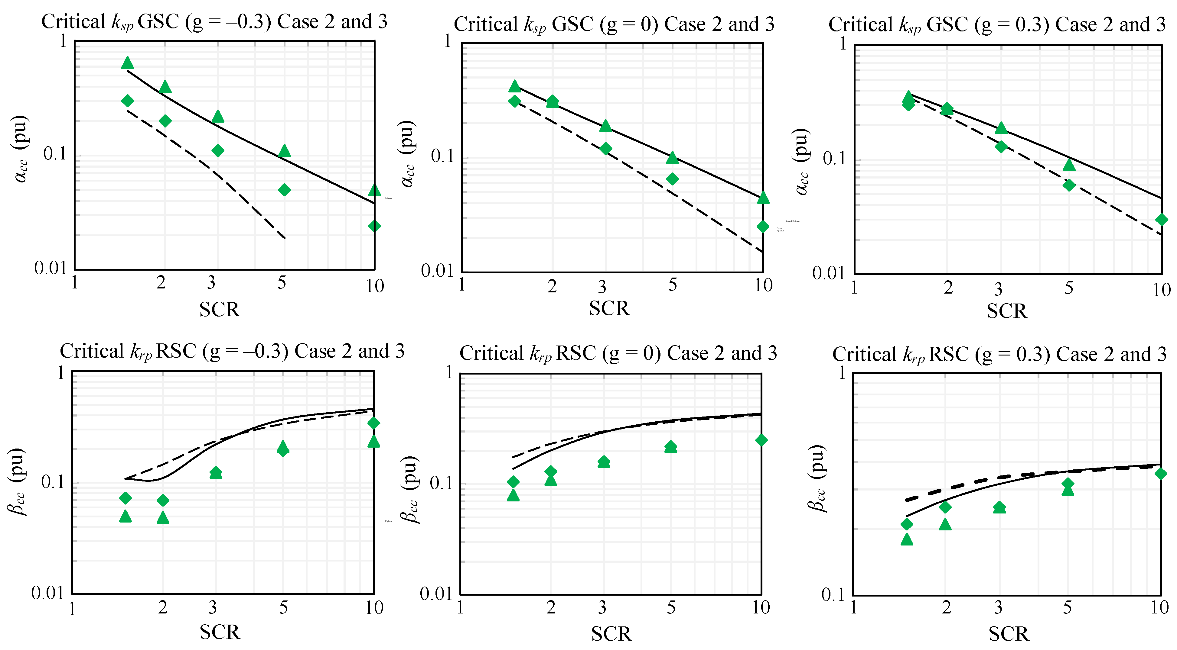
SCR influence on the extremum critical values (stability boundary) of the GSC (ksp) and RSC (krp) proportional gains, which cause DFIG instability, where the kPLLp and kPLLi values are equal to 0.5 (V·s)−1 and 5 V−1 (Case #2) and to 0.05 (V·s)−1 and 0.5 V−1 (Case #3), is studied. The results in per-unit values, i.e., αcc (pu) = ksp/ksp,Table 2 and βcc (pu) = krp/krp,Table 2, are shown in Figure 4 for different SCRs and three slips. The solid lines and the triangle dots represent the minimum critical values in Case #2 calculated with (42) and by PSCAD/EMTDC simulation, respectively, while the broken lines and the diamond dots represent the minimum critical values in Case #2. The following conclusions are obtained from the study:
- There are no maximum critical values of the kp that cause DFIG instability.
- As in Case #1, the lower the SCR, the higher the minimum values for critical GSC and PLL proportional gains.
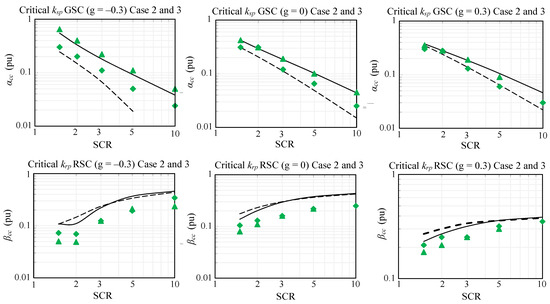
Figure 4.
Critical stator and rotor proportional gain for Case #2 and Case #3. Continuous line and triangle dots: Case #2 (kPLLp = 0.5). Broken line and diamond dots: Case #3 (kPLLp = 0.05). Continuous and broken lines: State-space predictions. Triangle dots and diamond dots: PSCAD/EMTDC simulations.
5.2. SCR Influence on Instability Frequency
This section covers the instability dq-frame frequencies corresponding to the minimum critical values of the GSC and RSC in Cases #1, #2, and #3. These frequencies are reflected in two abc instability frequencies, fp = fdq + f1 and fn = fdq − f1 (see Section 4), and are essential data to discover the origin of instability in the grid [1,2,3]. They are calculated from the state-space model (42) in Section 2 and Section 3 and validated by simulation using PSCAD/EMTDC. Figure 5 shows the results for different SCRs and three slips. The solid lines and the triangle dots represent the instability frequencies related to the minimum critical values of the GSC, and the broken line and diamond dots represent the instability frequency related to the minimum critical values of the RSC. The following conclusions are obtained from the study:
- The instability frequency due to the critical proportional gain of the RSC is close to 50 Hz and depends slightly on the SCR value.
- The instability frequency due to the critical proportional gain of the GSC ranges from 5 to 25 Hz and is significantly affected by the SCR and the DFIG slip or the power conditions.
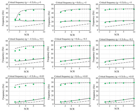
Figure 5.
Critical frequency for three cases with different PLL proportional gains. Continuous line and triangle dots: critical proportional gain (GSC). Broken line and diamond dots: critical proportional gain (RSC). Dotted and dashed line: critical proportional gain (GSC) for the model with an approximation of the capacitor as an ideal voltage source.
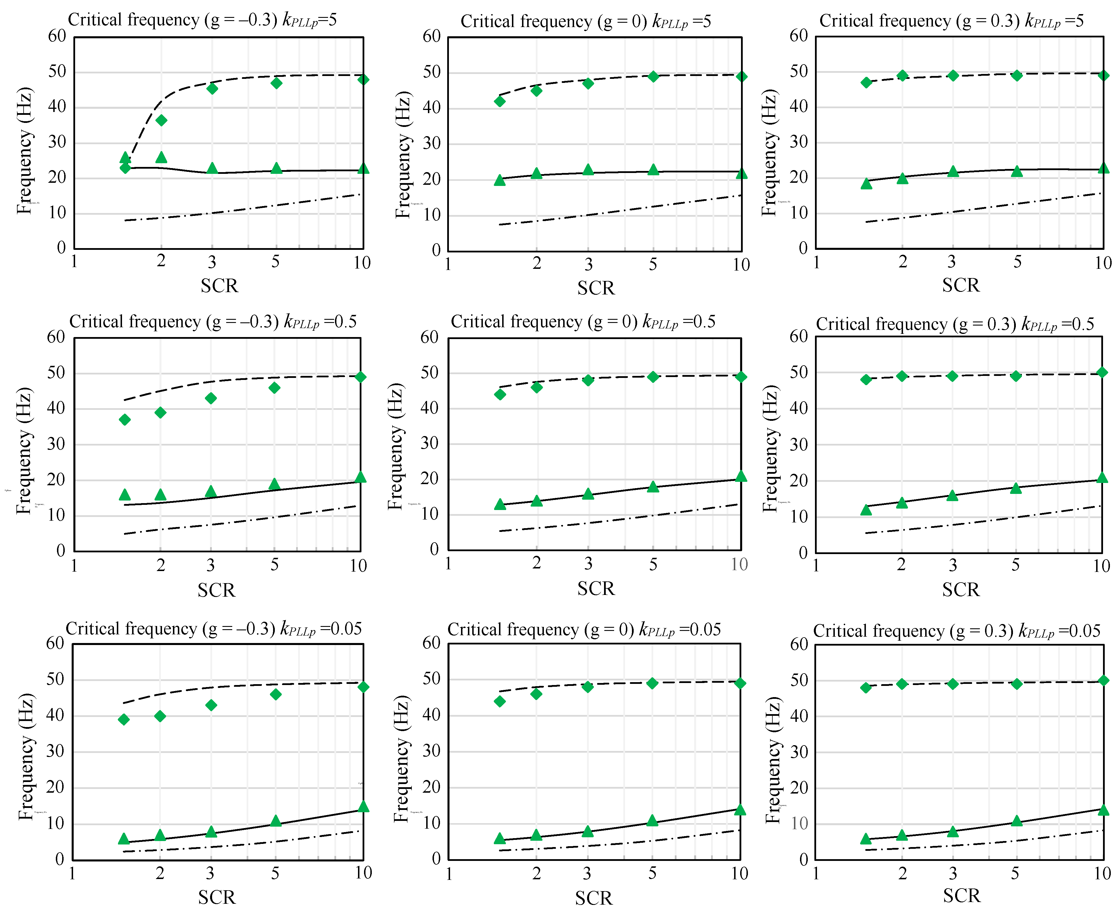
Figure 5 also compares the instability frequencies predicted by an approximate DFIG model with a DC voltage source instead of the DC capacitor (dotted and dashed line) [5] and the DFIG model in Section 2 and Section 3. It is worth noting that the approximate DFIG model, although widely used in impedance frequency domain studies, produces significant errors in predicting instabilities at low frequencies [5].
6. Conclusions
The major contribution of this paper is the accurate modeling of the small-signal DFIG state-space equations, which consider the rotor and the stator converters as well as the PLL effect. The analysis of the small signal model eigenvalues allows the stability boundary of the proportional control parameters of the rotor and the stator side converters to be determined as a function of the SCR as well as the PLL parameters. The study shows that, for the GSC and the PLL, the worst critical value of the proportional control parameters occurs for very weak grids (SCR ≈ 1.5), whereas for the RSC, the worst critical value occurs for very strong grids (SCR ≈ 10). In the RSC case, the worst is the ideal generator, with infinite SCR. Furthermore, it was verified that the instability frequency predicted by the approximate model, where the DC capacitor is considered an ideal source, has a non-negligible systematic error (greater than 10 Hz in the worst cases). The stability boundary of the control parameters as a function of the grid impedance values and the DFIG power predicted by the state-space model eigenvalues were validated by PSCAD/EMTDC time-domain simulation.
Author Contributions
Conceptualization and methodology, J.P. and L.S.; software development and validation, L.M. and J.P.; writing—original draft preparation, J.P. and L.S.; visualization, L.M. All authors have read and agreed to the published version of the manuscript.
Funding
This research was supported by Ministerio de Ciencia e Innovación, Agencia Estatal de Investigación, FEDER, UE (Grant PID2021-123633OB-C33 supported by MCIN/AEI/10.13039/501100011033/ FEDER, UE).
Data Availability Statement
The original contributions presented in the study are included in the article, further inquiries can be directed to the corresponding author.
Conflicts of Interest
The authors declare no conflicts of interest.
References
- Shair, J.; Xie, X.; Liu, W.; Li, X.; Li, H. Modeling and stability analysis methods for investigating subsynchronous control interaction in large-scale wind power systems. Renew. Sustain. Energy Rev. 2021, 135, 110420. [Google Scholar] [CrossRef]
- Cheng, Y.; Fan, L.; Rose, J.; Huang, S.-H.; Schmall, J.; Wang, X.; Xie, X.; Shair, J.; Ramamurthy, J.R.; Modi, N.; et al. Real-World Subsynchronous Oscillation Events in Power Grids with High Penetrations of Inverter-Based Resources. IEEE Trans. Power Syst. 2023, 38, 316–330. [Google Scholar] [CrossRef]
- Fan, L.; Miao, Z.; Shah, S.; Cheng, Y.; Rose, J.; Huang, S.-H.; Pal, B.; Xie, X.; Modi, N.; Wang, S.; et al. Real-World 20-Hz IBR Subsynchronous Oscillations: Signatures and Mechanism Analysis. IEEE Trans. Energy Convers. 2022, 37, 2863–2873. [Google Scholar] [CrossRef]
- Miao, Z. Impedance-Model-Based SSR Analysis for Type 3 Wind Generator and Series-Compensated Network. IEEE Trans. Energy Convers. 2012, 27, 984–991. [Google Scholar] [CrossRef]
- Song, Y.; Blaabjerg, F. Analysis of middle-frequency resonance in DFIG system considering phase-locked loop. IEEE Trans. Power Electron. 2018, 33, 343–356. [Google Scholar] [CrossRef]
- Ju, P.; Sun, B.; Shahidehpour, M.; Pan, X. Impedance Modeling and Analysis for DFIG-Based Wind Farm in SSO Studies. IEEE Access 2020, 8, 158380–158390. [Google Scholar] [CrossRef]
- Fan, L.; Kavasseri, R.; Miao, Z.L.; Zhu, C. Modeling of DFIG-Based Wind Farms for SSR Analysis. IEEE Trans. Power Deliv. 2010, 25, 2073–2082. [Google Scholar] [CrossRef]
- Fan, L.; Zhu, C.; Miao, Z.; Hu, M. Modal Analysis of a DFIG-Based Wind Farm Interfaced with a Series Compensated Network. IEEE Trans. Energy Convers. 2011, 26, 1010–1020. [Google Scholar] [CrossRef]
- Mishra, Y.; Mishra, S.; Li, F.; Dong, Z.Y.; Bansal, R.C. Small-Signal Stability Analysis of a DFIG-Based Wind Power System Under Different Modes of Operation. IEEE Trans. Energy Convers. 2009, 24, 972–982. [Google Scholar] [CrossRef]
- Tang, Y.; Ju, P.; He, H.; Qin, C.; Wu, F. Optimized Control of DFIG-Based Wind Generation Using Sensitivity Analysis and Particle Swarm Optimization. IEEE Trans. Smart Grid 2013, 4, 509–520. [Google Scholar] [CrossRef]
- Yang, L.; Xu, Z.; Østergaard, J.; Dong, Z.Y.; Wong, K.P.; Ma, X. Oscillatory Stability and Eigenvalue Sensitivity Analysis of A DFIG Wind Turbine System. IEEE Trans. Energy Convers. 2011, 26, 328–339. [Google Scholar] [CrossRef]
- Hu, J.; Huang, Y.; Wang, D.; Yuan, H.; Yuan, X. Modeling of Grid-Connected DFIG-Based Wind Turbines for DC-Link Voltage Stability Analysis. IEEE Trans. Sustain. Energy 2015, 6, 1325–1336. [Google Scholar] [CrossRef]
- Liu, R.; Yao, J.; Wang, X.; Sun, P.; Pei, J.; Hu, J. Dynamic Stability Analysis and Improved LVRT Schemes of DFIG-Based Wind Turbines During a Symmetrical Fault in a Weak Grid. IEEE Trans. Power Electron. 2020, 35, 303–318. [Google Scholar] [CrossRef]
- Huang, P.-H.; El Moursi, M.S.; Xiao, W.; Kirtley, J.L. Subsynchronous Resonance Mitigation for Series-Compensated DFIG-Based Wind Farm by Using Two-Degree-of-Freedom Control Strategy. IEEE Trans. Power Syst. 2015, 30, 1442–1454. [Google Scholar] [CrossRef]
- Mohammadpour, H.A.; Santi, E. Modeling and Control of Gate-Controlled Series Capacitor Interfaced With a DFIG-Based Wind Farm. IEEE Trans. Ind. Electron. 2015, 62, 1022–1033. [Google Scholar] [CrossRef]
- Ali, M.T.; Zhou, D.; Song, Y.; Ghandhari, M.; Harnefors, L.; Blaabjerg, F. Analysis and Mitigation of SSCI in DFIG Systems with Experimental Validation. IEEE Trans. Energy Convers. 2020, 35, 714–723. [Google Scholar] [CrossRef]
- Ostadi, A.; Yazdani, A.; Varma, R.K. Modeling and Stability Analysis of a DFIG-Based Wind-Power Generator Interfaced with a Series-Compensated Line. IEEE Trans. Power Deliv. 2009, 24, 1504–1514. [Google Scholar] [CrossRef]
- Mohammadpour, H.A.; Santi, E. SSR Damping Controller Design and Optimal Placement in Rotor-Side and Grid-Side Converters of Series-Compensated DFIG-Based Wind Farm. IEEE Trans. Sustain. Energy 2015, 6, 388–399. [Google Scholar] [CrossRef]
- Jia, Y.; Huang, T.; Li, Y.; Ma, R. Parameter Setting Strategy for the Controller of the DFIG Wind Turbine Considering the Small-Signal Stability of Power Grids. IEEE Access 2020, 8, 31287–31294. [Google Scholar] [CrossRef]
- Sun, B.; Ju, P.; Shahidehpour, M.; Pan, X. Calculation of Stable Domain of DFIG-Based Wind Farm in Series Compensated Power Systems. IEEE Access 2020, 8, 34900–34908. [Google Scholar] [CrossRef]
- Kong, L.; Xue, Y.; Qiao, L.; Wang, F. Review of Small-Signal Converter-Driven Stability Issues in Power Systems. IEEE Open Access J. Power Energy 2022, 9, 29–41. [Google Scholar] [CrossRef]
- Zhou, J.Z.; Ding, H.; Fan, S.; Zhang, Y.; Gole, A.M. Impact of Short-Circuit Ratio and Phase-Locked-Loop Parameters on the Small-Signal Behavior of a VSC-HVDC Converter. IEEE Trans. Power Deliv. 2014, 29, 2287–2296. [Google Scholar] [CrossRef]
- Pedra, J.; Sainz, L.; Monjo, L. Three-port small-signal admittance-based model of VSC for studies of multi-terminal HVDC hybrid AC/DC transmission grids. IEEE Trans. Power Syst. 2021, 36, 732–743. [Google Scholar] [CrossRef]
- Pedra, J.; Sainz, L.; Monjo, L. Comparison of small-signal admittance-based models of doubly-fed induction generators. Int. J. Electr. Power Energy Syst. 2023, 145, 108654. [Google Scholar] [CrossRef]
- Lesenne, J.; Notelet, F.; Seguier, G. Introduction a l’Electrotechnique Approfondie; Technique&Documentation: Paris, France, 1981. [Google Scholar]
- Kojooyan-Jafari, H.; Monjo, L.; Córcoles, F.; Pedra, J. Parameter Estimation of Wound-Rotor Induction Motors from Transient Measurements. IEEE Trans. Energy Convers. 2014, 29, 300–308. [Google Scholar] [CrossRef]
- Harnefors, L.; Bongiorno, M.; Lundberg, S. Input-Admittance Calculation and Shaping for Controlled Voltage-Source Converters. IEEE Trans. Ind. Electron. 2007, 54, 3323–3334. [Google Scholar] [CrossRef]
- Xu, Y.; Nian, H.; Wang, T.; Chen, L.; Zheng, T. Frequency coupling characteristic modeling and stability analysis of doubly fed induction generator. IEEE Trans. Energy Convers. 2018, 33, 1475–1486. [Google Scholar] [CrossRef]
- Medina, J.F.; Feijoo, A.E. Calculating steady-state operating conditions for double-fed induction generator wind turbines. IEEE Trans Power Syst. 2010, 25, 922–928. [Google Scholar] [CrossRef]


Disclaimer/Publisher’s Note: The statements, opinions and data contained in all publications are solely those of the individual author(s) and contributor(s) and not of MDPI and/or the editor(s). MDPI and/or the editor(s) disclaim responsibility for any injury to people or property resulting from any ideas, methods, instructions or products referred to in the content. |
© 2024 by the authors. Licensee MDPI, Basel, Switzerland. This article is an open access article distributed under the terms and conditions of the Creative Commons Attribution (CC BY) license (https://creativecommons.org/licenses/by/4.0/).