Review

Enhancing Performance of Permanent Magnet Motor Drives through Equivalent Circuit Models Considering Core Loss

by
Youguang Guo
*,
Yunfei Yu
,
Haiyan Lu
,
Gang Lei
and
Jianguo Zhu
Faculty of Engineering and Information Technology, University of Technology Sydney, Sydney, NSW 2007, Australia
*
Author to whom correspondence should be addressed.
Energies 2024, 17(8), 1837; https://doi.org/10.3390/en17081837
Submission received: 15 February 2024 / Revised: 6 April 2024 / Accepted: 10 April 2024 / Published: 11 April 2024
(This article belongs to the Section F: Electrical Engineering)

Abstract

:
Permanent magnet motors (PMMs) have emerged as key components in numerous industrial applications due to their high efficiency, compact size, and robust performance characteristics. However, to attain optimal performance in PMM drives, accurately predicting and mitigating core losses is paramount. This paper aims to provide a comprehensive review of advancements and methodologies for enhancing the performance of PMM drives by integrating equivalent circuit models (ECMs) that account for core losses. Firstly, the significance of core losses in motor drives is underscored, alongside a survey of research endeavors dedicated to core loss reduction. Notably, emphasis is placed on mathematical models offering both swift computation and reasonable accuracy. Subsequently, the paper delves into the development of ECMs, focusing on approaches adept at capturing core loss effects across diverse operating conditions. Moreover, this paper explores the utilization of these improved ECMs in the design and control of PMMs to achieve enhanced performance. By integrating core loss considerations into design and control strategies, PMM drives can optimize efficiency, torque production, and overall system performance. In summary, this paper may consolidate the current state-of-the-art techniques for enhancing PMM performance through the integration of core-loss-aware ECMs. It highlights key research directions and opportunities for further advancements in this critical area, aiming to foster the development of more efficient and reliable PMM-based systems for a wide range of industrial applications.

1. Introduction

The escalating focus on transportation electrification stems from its pivotal role in mitigating urban pollution concerns, where advanced electric motor systems play a central role. In the realm of electrified transport, the design of electric motors and their associated drive systems must prioritize high power density, efficiency, and reliability [1,2,3,4,5,6,7,8]. This emphasis becomes critical due to the typically restricted volume and weight allowances in electric vehicles (EVs). While increasing the motor’s operational speed and frequency is a seemingly straightforward approach among various techniques, it may lead to significant power loss, particularly via core loss, within the confined space. This could result in heightened temperatures, performance degradation, and potential motor failure.
To tackle these challenges, numerous research endeavors have been undertaken. These include the application of novel and advanced electromagnetic materials exhibiting lower specific power loss and improved high-frequency characteristics [9,10,11,12,13,14,15,16,17,18,19,20,21,22,23,24,25,26,27,28,29,30,31,32,33,34,35,36,37], advanced modeling of material properties that account for the actual operational conditions of electric motors [38,39,40,41,42], the implementation of application-oriented, system-level, multi-disciplinary, multi-objective robust design and optimization considering various factors, manufacturing uncertainties, and operational conditions [43,44,45,46,47,48], as well as the development of advanced control methods to optimize operational performance [49,50,51,52,53,54,55].
Certainly, various types of electric motors have been developed using cutting-edge electromagnetic materials to achieve low power loss and high power density. Some examples of these materials are very thin electrical steel sheets [9,10,11], high silicon electrical steel sheets [12,13,14], nanocrystalline and amorphous magnetic metals [15,16,17,18,19,20,21], soft magnetic composites [22,23,24,25,26,27,28,29,30,31], and high-temperature superconductors [32,33,34,35,36,37]. Realizing the full potential of these materials hinges upon a comprehensive understanding of their physical properties and their accurate mathematical modeling. This becomes particularly crucial given the relatively nascent nature of these materials, where their behaviors are not yet fully known. Consequently, some researchers have delved into investigating these material properties under varied conditions, encompassing two-dimensional (2D) and three-dimensional (3D) rotational magnetic flux densities of different magnitudes and frequencies, alongside diverse operational temperatures and mechanical stress factors [38,39,40,41,42].
To achieve advanced design optimization and precise system-level performance control of the motor drive [43,44,45,46,47,48,49,50,51,52,53,54,55], there is a strong demand for efficient mathematical models that offer swift computation without compromising accuracy. Typically, equivalent circuit models (ECMs) are favored for these purposes. However, traditional ECMs designed for permanent magnet (PM) motors (PMMs) often overlook core loss, potentially resulting in inaccurate calculations and subpar motor design or operational performance. Hence, there is a critical need for enhanced ECMs that account for core loss to enable effective design optimization and control of electric motors and drives [56,57].
The main objective of this paper is to explore an efficient computational method that balances accuracy and speed to enhance the performance of permanent magnet motor drives by integrating core loss considerations into equivalent circuit models. Conventional PMM ECMs often overlook core losses, resulting in inaccuracies when predicting motor behavior, particularly at high speeds, frequencies, or under dynamic loading conditions. By incorporating core loss effects into the equivalent circuit model, this paper strives to offer a more precise depiction of motor performance, facilitating improved design and control strategies to boost efficiency and overall motor performance. Through a combination of theoretical analysis and experimental validation conducted by various researchers, this paper endeavors to showcase the efficacy of the proposed models in accurately predicting motor behavior and optimizing drive performance.
The rest of the paper is organized as follows. Section 2 reviews the development of PMM ECMs including core loss components. In Section 3, performance enhancement using the improved ECMs considering core loss in the motor design and optimization is described. Section 4 presents the performance improvement of motor drives when the control algorithms involve the improved ECMs. Section 5 contains the discussion and conclusion.

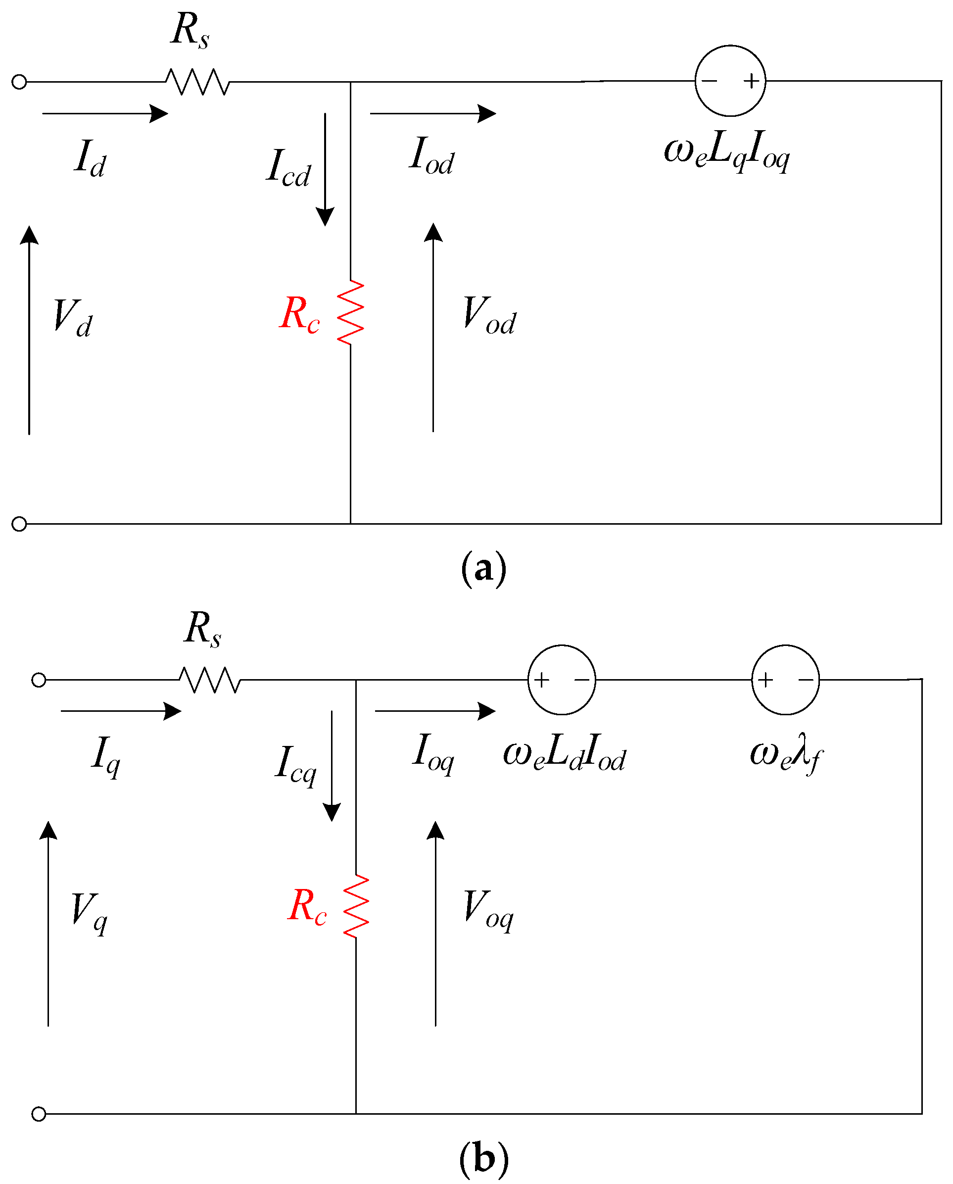
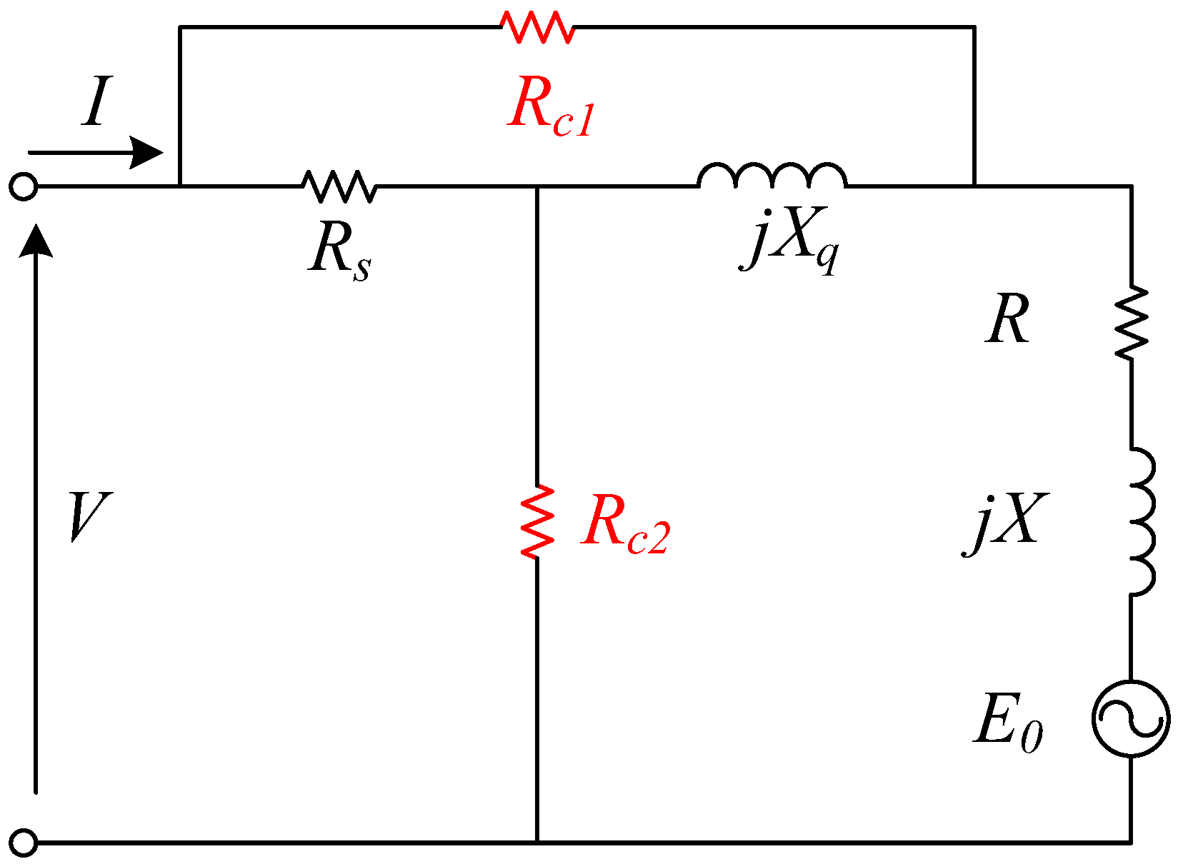
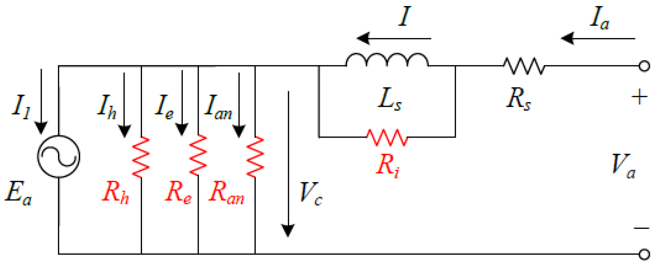
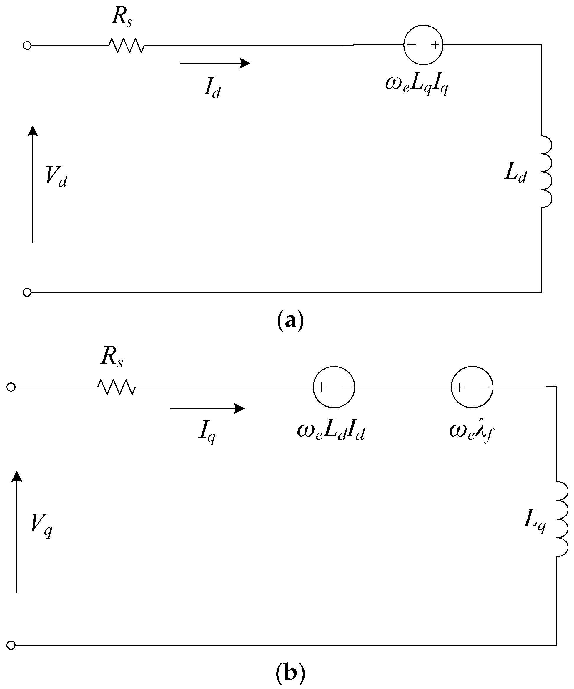
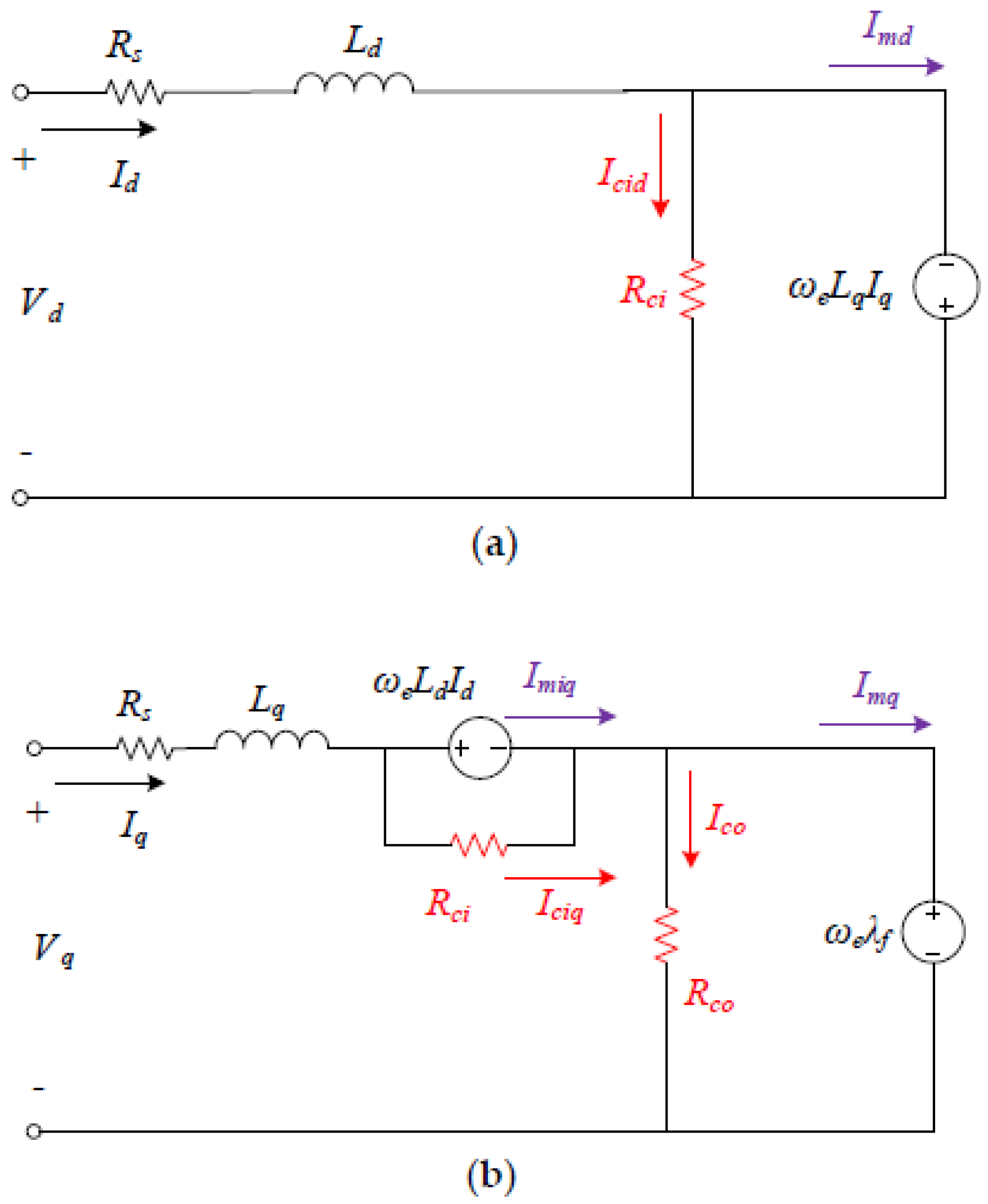
2. Development of PMM Equivalent Circuit Models Considering Core Loss

The incorporation of core loss considerations into ECMs has not adhered to a standard topology. Due to an incomplete understanding of the core loss mechanism, effectively modeling it within ECMs remains an unresolved challenge. Over the past few decades, diverse topologies have emerged to target specific functionalities. While integrating core loss into ECMs is crucial, this aspect has garnered limited attention, with only a handful of researchers delving into this matter.
The traditional approach to compute core loss (Pa) in scenarios involving alternating sinusoidal magnetic flux densities of frequency (f) and magnitude (BP) commonly depends on the three-term model [58,59,60], as depicted in Equation (1). These three terms specifically address the hysteresis loss element with coefficients Cha and h, the eddy current loss element with coefficient Cea, and an anomalous loss component characterized by coefficient Caa.
P a = C h a f B P h + C e a ( f B P ) 2 + C a a ( f B p ) 1.5
This method is established under specific and standardized working conditions, such as data being measured using an Epstein frame under one-dimensional (1D) alternating sinusoidal magnetization. However, certain areas within the electrical machine might encounter a rotating magnetic field, e.g., that characterized by nearly circular magnetic flux density patterns at the stator tooth root and elliptical patterns at the back of stator slots. Recent research has delved into the properties of materials under rotational magnetization and has discovered distinct behaviors compared to materials under alternating magnetization [61,62,63,64,65,66,67,68,69,70,71]. Despite these findings, there has not been a universally accepted standard for measuring rotational properties. The prevalent practice continues to rely on data obtained through 1D alternating sinusoidal magnetization. Consequently, this paper focuses on addressing the challenges associated with alternating core loss estimation in these varied magnetic field conditions.
In numerous scenarios, the third term, often referred to as the anomalous core loss or excess core loss, tends to be significantly smaller in comparison to the other two terms, making it possible to disregard it. The coefficient (h) associated with the hysteresis loss term typically falls within the range of 1.6 to 1.9. Hence, a factor of 2 may be applied for simplification, allowing the total core loss to be approximated using the square of the flux density magnitude (BP) for a fixed frequency, such as when the PMM operates at its synchronous speed. Given that the back electromotive force (emf), Ei, is directly proportional to the flux or flux density, the following formulae can be derived, where kc represents a coefficient:
P c k c E i 2
An equivalent core loss resistance can then be integrated in parallel with the back emf to predict the core loss, as reported in Figure 1 by Honsinger in 1980 [72], where r1 stands for the phase resistance, X1 denotes the leakage reactance per phase, Ei represents the back emf, and the power loss in rc signifies the core loss. The impedance Zi may encompass both the synchronous inductance and the distributed capacitance.
A comparable ECM was documented by Cobly and Novotny in 1987 [73]. As depicted in Figure 2, the leakage reactance X1 is integrated into the synchronous reactance X = ωLs, where Ls signifies the synchronous inductance and ω represents the angular frequency of the voltage or current. Additional parameters encompass the permanent magnet (PM) flux linkage, λ, and the stator phase resistance, Rs. Due to the negligible magnitude of the leakage reactance, Figure 2 closely mirrors the configuration presented in Figure 1.
At a specific speed or frequency, such as when the motor operates at its synchronous speed, the equivalent core loss resistance can be represented as constant. Upon having measured or calculated the rated back emf, E, and the no-load core loss, Pc, the core loss resistance can be determined using (3), where m denotes the number of motor phases.
R c m E 2 P c
In the operation of EVs, the electric motor necessitates a wide range of speed variation. To accommodate the fluctuating core loss corresponding to variable speeds, an adaptable equivalent core loss resistance may be required. In [74], Rc is modeled as a function of motor speed.
In synchronous machine analysis, the d- and q-axis ECMs are frequently employed, enabling the incorporation of the equivalent core loss resistance in parallel with the d- and q-axis magnetizing branches, respectively. Figure 3 provides a representation of the d- and q-axis ECMs for an interior PMM considering core loss [75,76].
It is well known that motor loading affects core loss [77]. For instance, in a PM transverse flux motor, the core loss at the rated current exceeds that at no load by 62% [78], potentially caused by the distortion in the distribution of flux density. Moreover, other studies have demonstrated substantial increases in core losses across various sections of the machine stator core [79]. However, despite these observed variations, the previously mentioned ECMs fail to consider the influence of motor loading. With fluctuations in load current, the terminal voltage remains nearly constant, maintaining the back emf and resulting in minimal changes to the core loss calculations due to the negligible voltage drop across the stator winding resistance.
To address the impact of load current on core loss, Consoli and Renna introduced an ECM with two equivalent core loss resistances, RC1 and RC2, as depicted in Figure 4 [80]. The current flowing through the core loss resistance, RC1, directly relates to the load current, and the power loss in RC1 accounts for the additional core loss attributed to the load. The power loss in Rc2 represents the no-load core loss. In the case of an interior PMM, the d-axis reactance (Xd) and q-axis reactance (Xq) differ, necessitating the use of two parameters, R and X, to accommodate the motor saliency. Here, R = (XdXq)sinαcosα and X = (XdXq)sin2α, where α represents the reaction angle. For the surface-mounted PMM, rotor saliency is absent, resulting in Xd = Xq, which renders both R and X as zero.
Consoli and Raciti introduced a comparable ECM, showcased in Figure 5, where the power loss in Rcv represents the core loss at no load, and the power loss in Rci accounts for the additional core loss due to the load current [81]. Given the very small voltage drop across Rs, the voltage across Rci in Figure 5 approximately equals that across Rc1 in Figure 4. Consequently, the ECMs depicted in Figure 4 and Figure 5 are fundamentally the same.

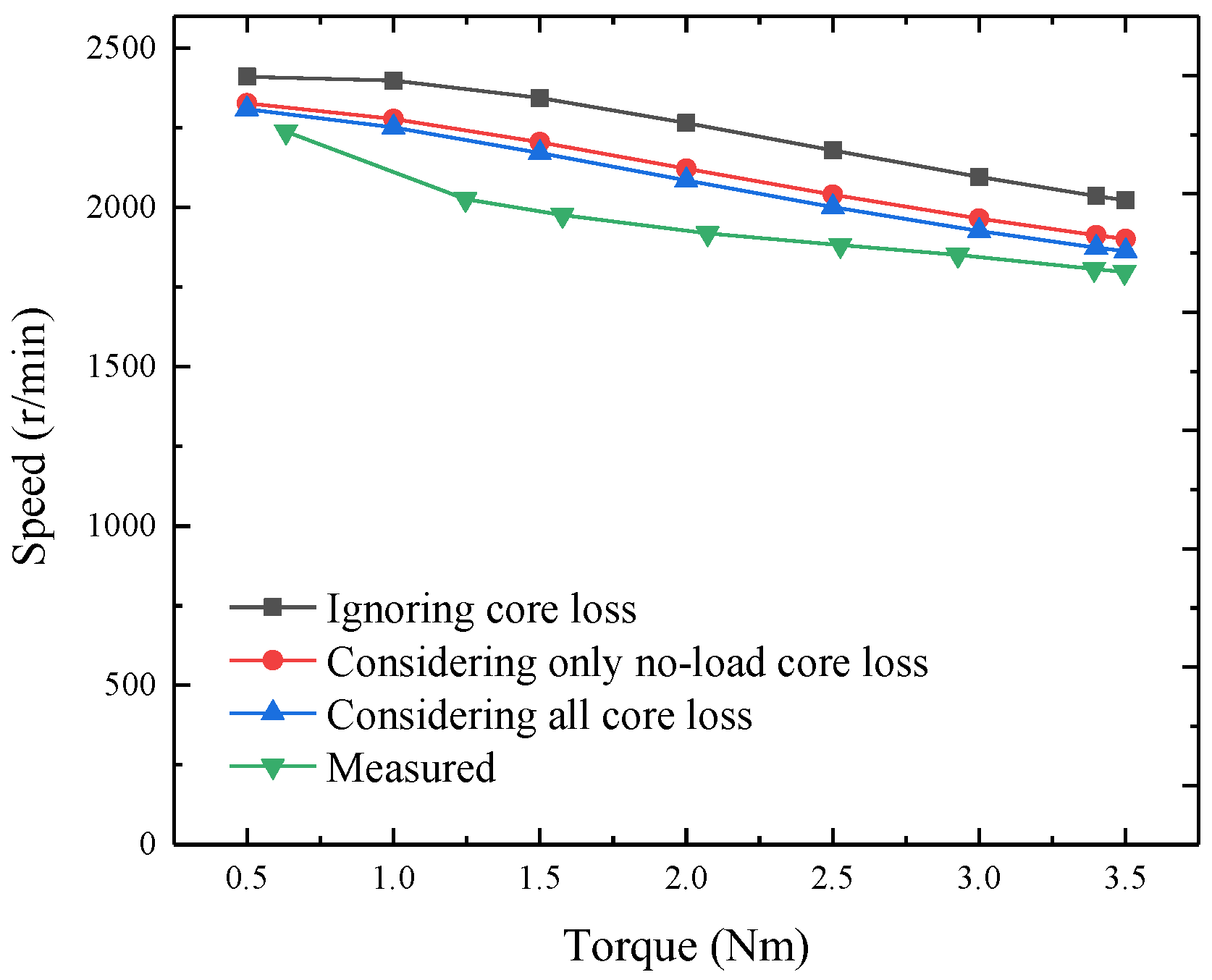
3. Performance Enhancement via Improved Design and Analysis Based on the Core Loss ECM

In motor design and optimization, ECMs are commonly utilized to analyze and compute various performance metrics such as the output torque versus speed curve, power loss, and efficiency. However, to be able to employ the ECM, all the circuit parameters such as resistance, inductances, back emf, and core loss resistances in the improved ECM must be predetermined. Determining these circuit parameters can be achieved through analytical formulae or numerical techniques. Analytical formulae offer quick computation but may sacrifice accuracy to some extent. Conversely, numerical techniques such as magnetic field finite element analysis provide highly accurate results but often require longer computation times. Therefore, in practice, a balance between computation time and accuracy needs to be struck when selecting the method for determining circuit parameters. Analytical formulae may suffice for initial estimations or rapid prototyping phases, while numerical techniques are better suited for detailed analysis and fine-tuning of motor designs. Ultimately, the choice of method depends on the specific requirements of the design task and the available computational resources.
While the motor characteristics are typically derived from the ECMs, conventional mathematical models of PMMs, such as differential equations or their corresponding ECMs, do not incorporate core losses. Consequently, they fail to accurately represent the motor’s behavior. This section elucidates how integrating a core loss ECM can enhance the predictive accuracy of a transverse flux PMM’s performance. The transverse flux PMM under consideration utilizes an SMC core, as outlined in [78]. The key parameters encompass the rated power of 640 W at a rated speed of 1800 rpm, stator phase resistance of 0.41 Ω, and inductance of 6.08 mH, operating with a back emf or current frequency of 300 Hz and outputting a torque of 3.4 Nm. The determination of no-load and load core losses involved employing the three-term model that considers the impact of rotational magnetic fluxes on hysteresis loss, utilizing the flux density locus under no-load or rated load at each element as a basis [82]. The no-load core loss was computed with different frequencies or speeds and it was found that the no-load loss increases almost linearly with the speed. The reason might be due to the SMC material, which has mainly hysteresis loss with negligible eddy current loss. The core losses resulting from different loads can be obtained.
The standard ECM, which does not account for core loss, was employed to derive the major external characteristic—the relationship between shaft output speed and mechanical torque. It is observed that the speed versus torque curve derived from this conventional ECM significantly deviates from experimental measurements. To address the impact of core loss, Figure 6 utilizes four equivalent core loss components. Here, Rh, Re, and Ran represent hysteresis loss, eddy current loss, and anomalous loss at no load, respectively. Additionally, Ri accounts for the extra core loss induced by the load current.
Utilizing this ECM, the subsequent equations can be deduced.
V a = E a + R s I a + j X s R i j X s + R i I a = E a + R s I a + X s 2 R i X s 2 + R i 2 I a + j X s R i 2 X s 2 + R i 2 I a
I a = I 1 + I h + I e + I a n
I 1 = 1 3 P e m E a cos φ
I h = E a R h
I e = E a R e
I a n = E a R a n
In the context of these equations, Pem represents the electromagnetic power of the motor and φ is the angle between the back electromotive force (Ea) and the armature current (I1). The definitions of the remaining symbols can be discerned from the circuit diagram. During operation under optimal brushless DC control, the armature current and back electromotive force are in the same phase, denoted as φ = 0.
The values of Rh, Re, and Ran can be obtained through curve-fitting techniques applied to the core losses across a range of motor speeds. To ascertain the equivalent core loss resistances, one must compute the core losses under no-load conditions at different speeds, as well as under various loads, either through theoretical calculations during the design phase or through experimental measurements once the motor prototype is accessible. As demonstrated in [82], calculations based on magnetic field finite element analysis exhibit a high level of accuracy compared to experimental results; consequently, the calculation results may be used in the design stage.
As an illustrative instance, the core loss resistances within the ECM for this transverse flux PMM can be derived through a process of curve-fitting the measured core losses across varying speeds. The intricate methodology delineating this determination process is explicated in the subsequent parts.
Upon the availability of the motor prototype, a comprehensive set of tests can commence. Initially, the prototype undergoes operation via a driver, with a torque transducer capturing motor speed and input torque measurements. Concurrently, the corresponding input power can be computed. Subtracting the copper loss in the windings, determined using the measured currents and winding resistances, yields the remaining power loss, encompassing both core loss and mechanical loss. To assess the mechanical loss, a “dummy rotor,” such as a wooden rotor with comparable structure and dimensions, may be employed. By conducting the aforementioned test using a dummy rotor, the mechanical loss is discerned as the discrepancy between the total input power and copper loss. Notably, as the wooden rotor does not generate a magnetic field, core loss is nonexistent. Assuming equivalence of mechanical loss at identical speeds for both real and dummy rotors, the core loss of the motor can then be deduced. Figure 7 displays a photograph of the testing setup of the transverse flux PMM prototype, and Table 1 presents the measured no-load core losses at different speeds.
When adjusting the motor speed, the VVVF (variable voltage variable frequency) strategy is frequently employed to maintain nearly constant magnetic flux, preventing ferromagnetic materials from either over-saturating or under-saturating. Consequently, the core loss described in Equation (1) becomes solely dependent on motor frequency or speed.
P c = P h + P e + P a n = k h n + k e n 2 + k a n n 1.5
The coefficients can be determined by fitting a curve to the data provided in Table 1, yielding values of kh = 0.01885, ke = 0.000010944, and kan = 0. By examining the ECM shown in Figure 6, one obtains
P c = 3 E a 2 ( 1 R h + 1 R e + 1 R a n ) = k h n + k e n 2 + k a n n 1.5
The PM flux is determined through finite element magnetic field analysis, yielding Φm = 0.00028 Wb. Consequently, the back emf can be calculated as Ea = 4.44fNΦm = 0.0259n, where f = pn/60 represents the frequency, with p = 10 being the number of pole pairs and N = 125 indicating the number of turns in the phase winding. Subsequently, the no-load core loss resistances can be worked out from Equation (11) and the results are Rh = 0.1068n, Re = 183.9, and Ran = ∞.
To ascertain the load core loss resistance, one must compute or measure the core losses under various load currents, encompassing the magnetic loss induced by the combined magnetic field of PMs and the load current. When operating at the rated speed of 1800 rpm and rated current of 5.5 A under optimal brushless DC control, where the armature current is controlled to have the same phase angle as the back emf, the core loss of the transverse flux PMM is calculated as 120.3 W, exhibiting an extra core loss PL = 50.9 W compared to no-load operation. Assuming that the load core loss is proportional to the square of the load current, the load core loss resistance can be determined as
R i = V X s 2 ( P L / 3 )
where VXs represents the voltage across the synchronous reactance Xs or the synchronous inductance Ls, which can be expressed as VXs = XsI = (πpn/30)LsI. Consequently, Ri can be derived as 0.00007228n2. Since the load core resistance value is substantially greater than the synchronous reactance value, the current flowing through the reactance approximates the armature current.
To analyze motor performance, the governing equations can be derived from Figure 6. For instance, the external characteristics, depicting the relationship between shaft output mechanical torque and shaft speed, are derived based on three scenarios: (i) disregarding core loss, wherein no core loss resistances are considered in the ECM, akin to the traditional ECM; (ii) accounting for no-load core losses exclusively, incorporating Rh, Re, and Ran but excluding Ri; (iii) incorporating all core losses, including Rh, Re, Ran, and Ri in the ECM. The findings reveal that mechanical characteristics analyzed using the ECM with all core losses exhibit the highest accuracy when compared to experimental measurements [57]. This advantage holds significant value for the development of advanced electric motors within the highly competitive global market or for specialized applications.
To present a quantitative comparison, Figure 8 depicts the speed versus torque curves of the transverse flux PMM, as measured on the prototype and calculated based on ECMs under three scenarios: (1) ignoring core loss [82]; (2) considering only no-load core loss; (3) considering all core losses. Notably, the first case (ignoring core loss) exhibits the largest deviation between the calculated and measured curves, with an average error of 13.6%. With the inclusion of no-load core loss, the error diminishes to 7.2%, and further decreases to 5.4% when both no-load loss and additional core loss induced by the load current are considered.

4. Performance Enhancement via Improved Control Based on the Core Loss ECM

The core loss ECM proves to be highly beneficial for optimizing the performance of electric motors, particularly in enhancing power efficiency [83]. Electric motors are the key components in electric vehicles EVs, which operate under varying speeds, loads, and environmental conditions. Consequently, sophisticated motor control strategies are essential, such as field-oriented control, direct torque control, and model predictive control [84,85,86,87,88,89]. Among the key control objectives is the minimization of power loss during operation, which can be achieved through the implementation of loss minimization control algorithms.
It is observed that these techniques have predominantly been developed for induction motor drives, thus warranting initial discussions on them. Comparing these traditional models with induction motor drives, where core losses are commonly considered although not high accuracy, highlights the necessity of integrating such considerations into PMM models to achieve heightened accuracy. Furthermore, aligning with induction motor drives enables the utilization of insights and methodologies established in that field, offering potential guidance for refining modeling and control strategies tailored to PMM drive.
Numerous research endeavors have explored loss minimization control strategies for induction motor drives [90,91,92,93]. In 2008, Uddin and Nam [90] introduced a loss-minimization control approach for induction motor drives, balancing accuracy with complexity. Yu et al. [91] further advanced this field in 2015 by proposing a loss calculation method based on the ECM within a synchronously rotating frame, incorporating core loss resistance. Their method significantly enhanced accuracy compared to conventional models, particularly benefiting EV efficiency. Eftekhari et al. [92], in 2020, developed a robust loss model based on ECM for flux optimization within predictive torque and flux control. This innovation addressed challenges associated with reduced model robustness and accuracy stemming from core loss resistance current. In 2023, Xiao et al. [93] introduced a loss minimization control approach based on time-harmonic ECM. Their method incorporates a cost function for loss minimization, further advancing the field’s sophistication and practical applicability.
Similarly, extensive research has delved into synchronous motors, including PMMs [94,95,96,97,98]. In 1994, Morimoto et al. [94] introduced an efficiency enhancement approach for PMM drives by regulating electromagnetic loss, encompassing both copper and core losses. Utilizing the ECM, they determined the optimal armature current vector by minimizing electromagnetic loss, factoring in motor operational speed and load conditions. In 2002, Mademlis and Margaris [95] presented a strategy for minimizing losses in interior PMM drives through optimal vector control or field-oriented control techniques. They derived a condition specifying the optimal d-axis current to minimize motor power losses. In 2016, Xie et al. [96] introduced dynamic loss minimization techniques for PMMs using finite control set-model predictive torque control. They computed core loss based on d-axis and q-axis ECMs, incorporating equivalent resistances for core losses in both the core and PMs. System efficiency optimization was achieved by controlling inverter losses and motor losses through a cost function and stator flux reference. In 2023, Li et al. [97] proposed efficiency improvements for flux-concentrating, field-modulated PMMs using model predictive torque control with harmonic-analysis-based loss minimization. Their approach integrated ECMs for the d-axis and q-axis, considering copper, core, and PM eddy current losses. This method enables online loss evaluation and real-time loss minimization, effectively enhancing motor efficiency across wide speed and torque ranges.
In 2024, Hou et al. [83] presented their study on enhancing the steady-state efficiency of an interior PMM by incorporating an improved ECM that accounts for core loss. The comparison was made through model predictive direct torque control, where the traditional ECM neglecting core loss was juxtaposed against the core loss-aware ECM [56]. Figure 9 and Figure 10 depict the respective illustrations of these ECMs.
Based on Figure 9 and Figure 10, the following voltage and current equations can be derived:
V d = R s I d ω e L q I q + d I d d t L d V q = R s I q + ω e L d I d + ω e λ f + d I q d t L q ,
d I d =   V d R s I d + ω e L q I q L d × d t d I q = V q R s I q ω e L d I d ω e λ f L q × d t .
By discretizing Equation (14), the next-step currents can be predicted;
I d k + 1 =   V d R s I d + ω e L q I q × T s L d + I d k I q k + 1 = V q R s I q ω e L d I d ω e λ f × T s L q + I q k .
The disparity lies in the prediction of currents. When employing the core loss ECMs, the actual motor currents are predicted through
I d = I c i d + I m d I q = I c i q + I m i q = I c o + I m q ,
I c i d = ω e L q I q R c o I c o = ω e λ f R c o ,
I m d k + 1 =   V d R s I d + ω e L q I q × T s L d + I d k ω e L q I q R c o I m q k + 1 = V q R s I q ω e L d I d ω e λ f × T s L q + I q k ω e λ f R c o .
To facilitate comparison, Equations (15) and (18) are individually employed within the framework of the model predictive control (MPC) strategy designed for driving the interior PMM [83]. These equations facilitate the determination of predictive values such as Id(k + 1) and Iq(k + 1) within the conventional ECM, as well as Imd(k + 1) and Imq(k + 1) within the enhanced ECM model that accounts for core losses. The calculated results from these equations offer insights into the behavior of the motor under varying conditions. Notably, these equations incorporate voltage components, denoted as Vd and Vq, which are controlled by the IGBT gates, as outlined in Table 2. Diverse voltage vectors are systematically applied to predict forthcoming currents, thereby eliciting anticipated motor performance characteristics. These predicted characteristics serve as a basis for comparison against predefined reference values, enabling a comprehensive assessment of motor behavior.
The selection process involves identifying the voltage vector that minimizes the cost function, thereby optimizing motor operation. This selected voltage vector is subsequently modulated for application, effectuating precise control modulation tailored to the motor’s requirements. For a comprehensive understanding of the intricacies involved, interested readers are directed to refer to the detailed analysis presented in [83].
The comparison results revealed that employing model predictive direct torque control based on Equation (18) yields enhanced motor performance compared to that based on Equation (15). Utilizing the core loss ECM results in a notable enhancement in the average efficiency across the speed range of 1000–6000 rpm, with an improvement of 12.7%. This underscores the advantage of utilizing the improved ECM for controlling motor operation.
In 2000, Fernandez-Bernal et al. [98] introduced a comprehensive loss model aimed at minimizing losses across a spectrum of electric motors, including DC motors, PMMs, synchronous reluctance motors, and induction motors. They asserted that this generalized model serves as a foundational framework from which specific loss models for various motor types can be derived.
In summary, motor drive control algorithms typically rely on the governing equations of the motor. Integrating core losses into the ECMs would undoubtedly enhance their accuracy and, subsequently, improve motor performance, especially in terms of power efficiency.

5. Discussion and Conclusions

In this study, the enhancement of performance in PMM drives is explored through the incorporation of equivalent circuit models that account for core losses. By integrating core loss considerations into the modeling framework, a more accurate representation of motor behavior is obtained, thereby facilitating improved control strategies and overall performance.
Through the investigation, the significance of accounting for core losses in PMM drives is highlighted. Core losses, consisting of hysteresis and eddy current losses, play a crucial role in determining motor efficiency and performance characteristics. Neglecting these losses can lead to inaccuracies in modeling and control, ultimately limiting the effectiveness of drive systems. The utilization of ECMs incorporating core loss components offers a more comprehensive approach to motor modeling. By accurately capturing core loss effects, these models enable more precise predictions of motor behavior under various operating conditions. This enhanced modeling capability lays the foundation for the development of advanced control algorithms aimed at optimizing motor performance.
Furthermore, the findings underscore the importance of considering core losses in the design and optimization of PMM drive systems. By incorporating core loss considerations early in the design process, engineers can make informed decisions to improve motor efficiency and overall system performance. Additionally, the study highlights the potential for utilizing advanced control strategies, such as predictive torque control, to further enhance performance gains afforded by accurate modeling.
It is important to acknowledge that while the proposed method offers valuable insights it also comes with constraints and limitations. Modeling core loss within ECMs proves challenging due to the intricate interplay of various factors and the complex mechanisms involved. While more sophisticated ECMs may offer higher accuracy in predicting core losses, they can simultaneously compromise their effectiveness in motor drive analysis, design, and control. Therefore, it is imperative to select an ECM that strikes a balance, considering the specific constraints and limitations inherent in the motor’s design and operation, such as speed range, load profile, and operational environments.
In conclusion, the investigation demonstrates the significant impact of incorporating equivalent circuit models considering core losses on the performance of PMM drives. By accurately accounting for core loss effects, these models enable more effective control strategies and facilitate the optimization of motor performance. Moving forward, continued research in this area holds promise for further advancements in PMM drive technology, ultimately leading to more efficient and reliable motor systems.

Author Contributions

Conceptualization, Y.G. and J.Z.; methodology, Y.G. and Y.Y.; software, Y.G. and Y.Y.; validation, Y.G., G.L., H.L. and J.Z.; formal analysis, Y.G. and Y.Y.; investigation, Y.G., H.L. and Y.Y.; resources, Y.G.; data curation, Y.G. and G.L.; writing—original draft preparation, Y.G. and Y.Y.; writing—review and editing, Y.G., H.L, G.L. and J.Z.; visualization, Y.G. and Y.Y.; supervision, Y.G., G.L. and J.Z.; project administration, Y.G.; funding acquisition, Y.G. and J.Z. All authors have read and agreed to the published version of the manuscript.

Funding

This research received no external funding.

Conflicts of Interest

The authors declare no conflict of interest.

References

  1. Zhu, Z.Q.; Howe, D. Electrical Machines and Drives for Electric, Hybrid, and Fuel Cell Vehicles. Proc. IEEE 2007, 95, 746–765. [Google Scholar] [CrossRef]
  2. Chan, C.; Chau, K.; Jiang, J.; Xia, W.; Zhu, M.; Zhang, R. Novel Permanent Magnet Motor Drives for Electric Vehicles. IEEE Trans. Ind. Electron. 1996, 43, 331–339. [Google Scholar] [CrossRef]
  3. Su, W.; Rahimi-Eichi, H.; Zeng, W.; Chow, M.-Y. A Survey on the Electrification of Transportation in a Smart Grid Environment. IEEE Trans. Ind. Inform. 2012, 8, 1–10. [Google Scholar] [CrossRef]
  4. Viswanath, A.; Farid, A.M. A Hybrid Dynamic System Model for the Assessment of Transportation Electrification. In Proceedings of the 2014 American Control Conference, Portland, OR, USA, 4–6 June 2014; pp. 4617–4623. [Google Scholar]
  5. Bilgin, B.; Emadi, A. Electric Motors in Electrified Transportation: A Step toward Achieving a Sustainable and Highly Efficient Transportation System. IEEE Power Electron. Mag. 2014, 1, 10–20. [Google Scholar] [CrossRef]
  6. Tan, D. Transportation Electrification: Challenges and Opportunities. IEEE Power Electron. Mag. 2016, 3, 50–52. [Google Scholar] [CrossRef]
  7. Fernandes, J.F.P.; Bhagubai, P.P.C.; Branco, P.J.C. Recent Developments in Electrical Machine Design for the Electrification of Industrial and Transportation Systems. Energies 2022, 15, 6390. [Google Scholar] [CrossRef]
  8. Guo, Y.; Liu, L.; Ba, X.; Lu, H.; Lei, G.; Yin, W.; Zhu, J. Designing High-Power-Density Electric Motors for Electric Vehicles with Advanced Magnetic Materials. World Electr. Veh. J. 2023, 14, 114. [Google Scholar] [CrossRef]
  9. Ueno, S.; Enokizono, M.; Mori, Y.; Yamazaki, K. Vector Magnetic Characteristics of Ultra-Thin Electrical Steel Sheet for Development of High-Efficiency High-Speed Motor. IEEE Trans. Magn. 2017, 53, 6300604. [Google Scholar] [CrossRef]
  10. Pei, R.; Zeng, L.; Gao, L. Studies of Core Loss of Thin Non-oriented Electrical Steel for Electrical Vehicle Traction Motors. In Proceedings of the 2018 21st International Conference on Electrical Machines and Systems (ICEMS), Jeju, Republic of Korea, 7–10 October 2018; pp. 2715–2718. [Google Scholar]
  11. Huynh, T.; Hsieh, M.-F. Performance Evaluation of Thin Electrical Steels Applied to Interior Permanent Magnet Motor. In Proceedings of the 2016 19th International Conference on Electrical Machines and Systems (ICEMS), Chiba, Japan, 13–16 November 2016; pp. 1–6. [Google Scholar]
  12. Hasegawa, M.; Tanaka, N.; Chiba, A.; Fukao, T. The Operation Analysis and Efficiency Improvement of Switched Reluctance Motors with High Silicon Steel. In Proceedings of the Power Conversion Conference-Osaka 2002 (Cat. No.02TH8579), Osaka, Japan, 2–5 April 2002; pp. 981–986. [Google Scholar]
  13. Ou, J.; Liu, Y.; Breining, P.; Gietzelt, T.; Gietzelt, T.; Wunsch, T.; Doppelbauer, M. Study of the Electromagnetic and Mechanical Properties of a High-silicon Steel for a High-speed Interior PM Rotor. In Proceedings of the 2019 22nd International Conference on Electrical Machines and Systems (ICEMS), Harbin, China, 11–14 August 2019; pp. 1–4. [Google Scholar]
  14. Ma, D.; Li, J.; Tian, B.; Zhang, H.; Li, M.; Pei, R. Studies on Loss of a Motor Iron Core with High Silicon Electrical Steel Considering Temperature and Compressive Stress Factors. In Proceedings of the 2022 IEEE 5th International Electrical and Energy Conference (CIEEC), Nanjing, China, 27–29 May 2022; pp. 4243–4248. [Google Scholar]
  15. Jensen, C.C.; Profumo, F.; Lipo, T.A. A Low-Loss Permanent-Magnet Brushless dc Motor Utilizing Tape Wound Amorphous Iron. IEEE Trans. Ind. Appl. 1992, 28, 646–651. [Google Scholar] [CrossRef]
  16. Wang, Z.; Enomoto, Y.; Ito, M.; Masaki, R.; Morinaga, S.; Itabashi, H.; Tanigawa, S. Development of a Permanent Magnet Motor Utilizing Amorphous Wound Cores. IEEE Trans. Magn. 2010, 46, 570–573. [Google Scholar] [CrossRef]
  17. Wang, L.; Li, J.; Li, S.; Zhang, G.; Huang, S. Development of the New Energy-Efficient Amorphous Iron Based Electric Motor. In Proceedings of the 2011 International Conference on Computer Distributed Control and Intelligent Environmental Monitoring, Changsha, China, 19–20 February 2011; pp. 2059–2061. [Google Scholar]
  18. Fan, T.; Li, Q.; Wen, X. Development of a High Power Density Motor Made of Amorphous Alloy Cores. IEEE Trans. Ind. Electron. 2014, 61, 4510–4518. [Google Scholar] [CrossRef]
  19. Tomioka, T.; Akatsu, K. Study of High-Speed SRM with Amorphous Steel Sheet for EV. In Proceedings of the 2016 19th International Conference on Electrical Machines and Systems (ICEMS), Chiba, Japan, 13–16 November 2016; pp. 1–6. [Google Scholar]
  20. Fan, Z.; Yi, H.; Xu, J.; Xie, K.; Qi, Y.; Ren, S.; Wang, H. Performance Study and Optimization Design of High-Speed Amorphous Alloy Induction Motor. Energies 2021, 14, 2468. [Google Scholar] [CrossRef]
  21. Guo, Y.; Liu, L.; Yin, W.; Lu, H.; Lei, G.; Zhu, J. Designing High-Power-Density Electromagnetic Devices with Nanocrystalline and Amorphous Magnetic Materials. Nanomaterials 2023, 13, 1963. [Google Scholar] [CrossRef]
  22. Persson, M.; Jansson, P.; Jack, A.G.; Mecrow, B.C. Soft Magnetic Composite Materials—Use for Electrical Machines. In Proceedings of the 1995 Seventh International Conference on Electrical Machines and Drives (Conf. Publ. No. 412), Durham, UK, 11–13 September 1995; pp. 242–246. [Google Scholar]
  23. Jack, A.G.; Mecrow, B.C.; Maddison, C.P. Combined Radial and Axial Magnet Motors Using Soft Magnetic Composites. In Proceedings of the 1999 Ninth International Conference on Electrical Machines and Drives (Conf. Publ. No. 468), Canterbury, UK, 1–3 September 1999; pp. 25–29. [Google Scholar]
  24. Cvetkovski, G.; Petkovska, L.; Cundev, M.; Gair, S. Improved Design of a Novel PM Disk Motor by Using Soft Magnetic Composite Material. IEEE Trans. Magn. 2002, 38, 3165–3167. [Google Scholar] [CrossRef]
  25. Qu, R.; Kliman, G.B.; Carl, R. Split-Phase Claw-Pole Induction Machines with Soft Magnetic Composite Cores. In Proceedings of the 39th IAS Annual Meeting, Seattle, WA, USA, 3–7 October 2004; pp. 2514–2519. [Google Scholar]
  26. Guo, Y.; Zhu, J.G.; Dorrell, D.G. Design and Analysis of a Claw Pole Permanent Magnet Motor with Molded SMC Core. IEEE Trans. Magn. 2009, 45, 4582–4585. [Google Scholar]
  27. Zhu, J.G.; Guo, Y.G.; Lin, Z.W.; Li, Y.J.; Huang, Y.K. Development of PM Transverse Flux Motors with Soft Magnetic Composite Cores. IEEE Trans. Magn. 2011, 47, 4376–4383. [Google Scholar] [CrossRef]
  28. Doering, J.; Steinborn, G.; Hofmann, W. Torque, Power, Losses, and Heat Calculation of a Transverse Flux Reluctance Machine with Soft Magnetic Composite Materials and Disk-Shaped Rotor. IEEE Trans. Ind. Appl. 2015, 51, 1494–1504. [Google Scholar] [CrossRef]
  29. Liu, C.; Lei, G.; Ma, B.; Wang, Y.; Guo, Y.; Zhu, J. Development of a New Low-Cost 3-D Flux Transverse Flux FSPMM with Soft Magnetic Composite Cores and Ferrite Magnets. IEEE Trans. Magn. 2017, 53, 8109805. [Google Scholar] [CrossRef]
  30. Ahmed, N.; Atkinson, G.J. A Review of Soft Magnetic Composite Materials and Applications. In Proceedings of the 2022 International Conference on Electrical Machines (ICEM), Valencia, Spain, 5–8 September 2022; pp. 551–557. [Google Scholar]
  31. Guo, Y.; Ba, X.; Liu, L.; Lu, H.; Lei, G.; Yin, W.; Zhu, J. A Review of Electric Motors with Soft Magnetic Composite Cores for Electric Drives. Energies 2023, 16, 2053. [Google Scholar] [CrossRef]
  32. Snitchler, G.; Gamble, B.; Kalsi, S.S. The Performance of a 5 MW High Temperature Superconductor Ship Propulsion Motor. IEEE Trans. Appl. Supercond. 2005, 15, 2206–2209. [Google Scholar] [CrossRef]
  33. Gonzalez-Parada, A.; Espinosa-Loza, F.J.; Castaneda-Miranda, A.; Bosch-Tous, R.; Granados-Garcia, X. Application of HTS BSCCO Tapes in an Ironless Axial Flux Superconductor Motor. IEEE Trans. Appl. Supercond. 2012, 22, 5201004. [Google Scholar] [CrossRef]
  34. Jin, J.X.; Zheng, L.H.; Guo, Y.G.; Grantham, C.; Sorrell, C.C.; Xu, W. High-Temperature Superconducting Linear Synchronous Motors Integrated with HTS Magnetic Levitation Components. IEEE Trans. Appl. Supercond. 2012, 22, 5202617. [Google Scholar]
  35. Moon, H.; Kin, Y.-C.; Park, H.-J.; Park, M.; Yu, I.-K. Development of a MW-Class 2G HTS Ship Propulsion Motor. IEEE Trans. Appl. Supercond. 2016, 26, 5203805. [Google Scholar] [CrossRef]
  36. Liu, B.; Badcock, R.; Shu, H.; Tan, L.; Fang, J. Electromagnetic Characteristic Analysis and Optimization Design of a Novel HTS Coreless Induction Motor for High-Speed Operation. IEEE Trans. Appl. Supercond. 2018, 28, 5202405. [Google Scholar] [CrossRef]
  37. Lee, J.-Y.; Nam, G.-D.; Yu, I.-K.; Park, M. Design and Characteristic Analysis of an Axial Flux High-Temperature Superconducting Motor for Aircraft Propulsion. Materials 2023, 16, 3587. [Google Scholar] [CrossRef]
  38. Guo, Y.G.; Zhu, J.G.; Lin, Z.W.; Zhong, J.J.; Wu, W. Measurement and Modeling of Core Losses of Soft Magnetic Composites Under 3-D Magnetic Excitations in Rotating Motors. IEEE Trans. Magn. 2005, 41, 3925–3927. [Google Scholar]
  39. Sievert, J. Two-dimensional Magnetic Measurement-History and the Achievements of the Workshop. Przeg. Elektrot. 2011, 87, 2–10. [Google Scholar]
  40. Guo, Y.; Liu, L.; Ba, X.; Lu, H.; Lei, G.; Sarker, P.; Zhu, J. Characterization of Rotational Magnetic Properties of Amorphous Metal Materials for Advanced Electrical Machine Design and Analysis. Energies 2022, 15, 7798. [Google Scholar] [CrossRef]
  41. Guo, Y.; Liu, L.; Ba, X.; Lu, H.; Lei, G.; Yin, W.; Zhu, J. Measurement and Modeling of Magnetic Materials under 3D Vectorial Magnetization for Advanced Electrical Machine Design and Analysis. Energies 2023, 16, 417. [Google Scholar] [CrossRef]
  42. Soomro, W.A.; Guo, Y.; Lu, H.; Jin, J.X.; Shen, B.; Zhu, J.G. AC Loss in High-Temperature Superconducting Bulks Subjected to Alternating and Rotating Magnetic Fields. Materials 2023, 16, 633. [Google Scholar] [CrossRef]
  43. Sun, X.; Shi, Z.; Cai, Y.; Lei, G.; Guo, Y.; Zhu, J. Driving-Cycle-Oriented Design Optimization of a Permanent Magnet Hub Motor Drive System for a Four-Wheel-Drive Electric Vehicle. IEEE Trans. Transp. Electrif. 2020, 6, 1115–1125. [Google Scholar] [CrossRef]
  44. Lei, G.; Wang, T.; Zhu, J.; Guo, Y.; Wang, S. System-Level Design Optimization Method for Electrical Drive Systems—Robust Approach. IEEE Trans. Ind. Electron. 2015, 62, 4702–4713. [Google Scholar] [CrossRef]
  45. Salimi, A.; Lowther, D.A. On the Role of Robustness in Multi-Objective Robust Optimization: Application to an IPM Motor Design Problem. IEEE Trans. Magn. 2016, 52, 8102304. [Google Scholar] [CrossRef]
  46. Zhu, X.; Shu, Z.; Quan, L.; Xiang, Z.; Pan, X. Multi-Objective Optimization of an Outer-Rotor V-Shaped Permanent Magnet Flux Switching Motor Based on Multi-Level Design Method. IEEE Trans. Magn. 2016, 52, 8205508. [Google Scholar] [CrossRef]
  47. Ma, B.; Lei, G.; Zhu, J.; Guo, Y.; Liu, C. Application-Oriented Robust Design Optimization Method for Batch Production of Permanent-Magnet Motors. IEEE Trans. Ind. Electron. 2018, 65, 1728–1739. [Google Scholar] [CrossRef]
  48. Lei, G.; Bramerdorfer, G.; Ma, B.; Guo, Y.; Zhu, J. Robust Design Optimization of Electrical Machines: Multi-Objective Approach. IEEE Trans. Energy Convers. 2021, 36, 390–401. [Google Scholar] [CrossRef]
  49. Liu, C.-T.; Chiang, T.; Zamora, J.; Lin, S. Field-Oriented Control Evaluations of a Single-Sided Permanent Magnet Axial-Flux Motor for an Electric Vehicle. IEEE Trans. Magn. 2003, 39, 3280–3282. [Google Scholar]
  50. Men, X.; Guo, Y.; Wu, G.; Chen, S.; Shi, C. Implementation of an Improved Motor Control for Electric Vehicles. Energies 2022, 15, 4833. [Google Scholar] [CrossRef]
  51. Zhang, L.; Fan, Y.; Cui, R.; Lorenz, R.D.; Cheng, M. Fault-Tolerant Direct Torque Control of Five-Phase FTFSCW-IPM Motor Based on Analogous Three-Phase SVPWM for Electric Vehicle Applications. IEEE Trans. Veh. Technol. 2018, 67, 910–919. [Google Scholar] [CrossRef]
  52. Sun, X.; Diao, K.; Lei, G.; Guo, Y.; Zhu, J. Direct Torque Control Based on a Fast Modeling Method for a Segmented-Rotor Switched Reluctance Motor in HEV Application. IEEE J. Emerg. Sel. Top. Power Electron. 2019, 9, 232–241. [Google Scholar] [CrossRef]
  53. Wang, T.; Liu, C.; Lei, G.; Guo, Y.; Zhu, J. Model Predictive Direct Torque Control of Permanent Magnet Synchronous Motors with Extended Set of Voltage Space Vectors. IET Electr. Power Appl. 2017, 11, 1376–1382. [Google Scholar] [CrossRef]
  54. Wu, H.; Si, Z.; Li, Z. Trajectory Tracking Control for Four-Wheel Independent Drive Intelligent Vehicle Based on Model Pre-dictive Control. IEEE Access 2020, 8, 73071–73081. [Google Scholar] [CrossRef]
  55. Machacek, D.T.; Barhoumi, K.; Ritzmann, J.M.; Huber, T.; Onder, C.H. Multi-Level Model Predictive Control for the Energy Management of Hybrid Electric Vehicles Including Thermal Derating. IEEE Trans. Veh. Technol. 2022, 71, 10400–10414. [Google Scholar] [CrossRef]
  56. Ba, X.; Gong, Z.; Guo, Y.; Zhang, C.; Zhu, J. Development of Equivalent Circuit Models of Permanent Magnet Synchronous Motors Considering Core Loss. Energies 2022, 15, 1995. [Google Scholar] [CrossRef]
  57. Guo, Y.; Ba, X.; Liu, L.; Hou, L.; Lei, G.; Zhu, J. Performance Enhancement of Permanent Magnet Synchronous Motors Based on Improved Circuit Models. In Proceedings of the 25th International Conference on Electrical Machines and Systems (ICEMS), Chiang Mai, Thailand, 29 November–2 November 2023; pp. 1–6. [Google Scholar]
  58. Fiorillo, F.; Novikov, A. An Improved Approach to Power Losses in Magnetic Laminations under Nonsinusoidal Induction Waveform. IEEE Trans. Magn. 1990, 26, 2904–2910. [Google Scholar] [CrossRef]
  59. Guo, Y.; Zhu, J.; Zhong, J.; Wu, W. Core Losses in Claw Pole Permanent Magnet Machines with Soft Magnetic Composite Core. IEEE Trans. Magn. 2003, 39, 3199–3201. [Google Scholar]
  60. Ionel, D.M.; Poescu, M.; McGilp, M.I.; Miller, T.J.E.; Dellinger, S.J.; Heidman, R.J. Computation of Core Losses in Electrical Machines Using Improved Models for Laminated Steel. IEEE Trans. Ind. Appl. 2007, 43, 1554–1564. [Google Scholar] [CrossRef]
  61. Brix, W.; Hempel, K.A.; Schulte, F.J. Improved Method for the Investigations of the Rotational Magnetization Process in Electrical Steel Sheets. IEEE Trans. Magn. 1984, 20, 1708–1710. [Google Scholar] [CrossRef]
  62. Sievert, J. Recent Advances in the One- and Two-dimensional Magnetic Measurement Technique for Electrical Sheet Steel. IEEE Trans. Magn. 1990, 26, 2553–2558. [Google Scholar] [CrossRef]
  63. Bertotti, G.; Boglietti, A.; Chiampi, M.; Chiarabaglio, D.; Fiorillo, F.; Lazzari, M. An Improved Estimation of Iron Losses in Rotating Machines. IEEE Trans. Magn. 1991, 27, 5007–5009. [Google Scholar] [CrossRef]
  64. Stranges, N.; Findlay, R.D. Importance of Rotational Iron Loss Data for Accurate Prediction of Rotating Machine Core Losses. In Proceedings of the 29th IEEE Industry Applications Society Annual Meeting (IAS), Denver, CO, USA, 2–6 October 1994; pp. 123–127. [Google Scholar]
  65. Enokizono, M.; Tanabe, I. Studies on a New Simplified Rotational Loss Tester. IEEE Trans. Magn. 1997, 33, 4020–4022. [Google Scholar] [CrossRef]
  66. Zhu, J.G.; Ramsden, V.S. Improved Formulations for Rotational Core Losses in Rotating Electrical Machines. IEEE Trans. Magn. 1998, 34, 2234–2242. [Google Scholar]
  67. Guo, Y.; Zhu, J.G.; Zhong, J.; Lu, H.; Jin, J.X. Measurement and Modeling of Rotational Core Losses of Soft Magnetic Materials Used in Electrical Machines: A Review. IEEE Trans. Magn. 2008, 44, 279–291. [Google Scholar]
  68. Guo, Y.; Zhu, J.; Lu, H.; Lin, Z.; Li, Y. Core Loss Calculations for Soft Magnetic Composite Electrical Machines. IEEE Trans. Magn. 2012, 48, 3112–3115. [Google Scholar] [CrossRef]
  69. Li, J.; Zhang, Y.; Zhang, D.; Ren, Z.; Koh, C.S. Analysis of Rotational Hysteresis Property in a Transformer Core Based on an Inverse Jiles-Atherton Hysteresis Model Coupled with Finite Element Method. In Proceedings of the 23rd International Conference on Electrical Machines and Systems (ICEMS), Hamamastsu, Japan, 24–27 November 2020; pp. 1027–1030. [Google Scholar]
  70. Sarker, P.C.; Guo, Y.; Lu, H.Y.; Zhu, J.G. Measurement and Modeling of Rotational Core Loss of Fe-Based Amorphous Magnetic Material Under 2-D Magnetic Excitation. IEEE Trans. Magn. 2021, 57, 8402008. [Google Scholar] [CrossRef]
  71. Yan, J.; Di, C.; Bao, X.; Zhu, Q. Iron Loss Model for Induction Machines Considering the Influence of Rotational Iron Losses. IEEE Trans. Energy Convers. 2023, 38, 971–981. [Google Scholar] [CrossRef]
  72. Honsinger, V. Performance of Polyphase Permanent Magnet Machines. IEEE Trans. Power App. Syst. 1980, PAS-99, 1510–1518. [Google Scholar] [CrossRef]
  73. Colby, R.S.; Novotny, D.W. Efficient Operation of Surface-Mounted PM Synchronous Motors. IEEE Trans. Ind. Appl. 1987, IA-23, 1048–1054. [Google Scholar] [CrossRef]
  74. Ba, X.; Guo, Y.; Zhu, J.G.; Zhang, C. An Equivalent Circuit Model for Predicting the Core Loss in a Claw-Pole Permanent Magnet Motor with Soft Magnetic Composite Core. IEEE Trans. Magn. 2018, 54, 8206706. [Google Scholar] [CrossRef]
  75. Lee, J.Y.; Lee, S.H.; Lee, G.H.; Hong, J.P.; Hur, J. Determination of Parameters Considering Magnetic Nonlinearity in an Interior Permanent Magnet Synchronous Motor. IEEE Trans. Magn. 2006, 42, 1303–1306. [Google Scholar]
  76. Hur, J. Characteristic Analysis of Interior Permanent-Magnet Synchronous Motor in Electrohydraulic Power Steering systems. IEEE Trans. Ind. Electron. 2008, 55, 2316–2323. [Google Scholar]
  77. Rachev, S.; Stefanov, D.; Dimitrov, L.; Koeva, D. Evaluation of Electric Power Losses of an Induction Motor Driving a Compact Electric Vehicles at Change of Parameters and Loads. In Proceedings of the Electric Vehicles International Conference & Show (EV2019), Bucuresti, Romania, 3–4 October 2019; pp. 1–5. [Google Scholar]
  78. Guo, Y.; Zhu, J.G.; Watterson, P.A.; Wu, W. Development of a PM Transverse Flux Motor with Soft Magnetic Composite Core. IEEE Trans. Energy Convers. 2006, 21, 426–434. [Google Scholar] [CrossRef]
  79. Tao, D.; Zhou, K.L.; Lv, F.; Dou, Q.; Wu, J.; Sun, Y.; Zou, J. Magnetic Field Characteristics and Stator Core Losses of High-Speed Permanent Magnet Synchronous Motors. Energies 2020, 13, 535. [Google Scholar] [CrossRef]
  80. Consoli, A.; Renna, G. Interior Type Permanent Magnet Synchronous Motor Analysis by Equivalent Circuits. IEEE Trans. Energy Convers. 1989, 4, 681–689. [Google Scholar] [CrossRef]
  81. Consoli, A.; Raciti, A. Analysis of Permanent Magnet Synchronous Motors. IEEE Trans. Ind. Appl. 1991, 27, 350–354. [Google Scholar] [CrossRef]
  82. Guo, Y.; Zhu, J.; Lu, H.; Li, Y.; Jin, J. Core Loss Computation in a Permanent Magnet Transverse Flux Motor with Rotating Fluxes. IEEE Trans. Magn. 2014, 50, 6301004. [Google Scholar] [CrossRef]
  83. Hou, L.; Guo, Y.; Ba, X.; Lei, G.; Zhu, J. Efficiency Improvement of Permanent Magnet Synchronous Motors Using Model Predictive Control Considering Core Loss. Energies 2024, 17, 773. [Google Scholar] [CrossRef]
  84. Li, Y.; Gerling, D.; Ma, J.; Liu, J.; Yu, Q. The Comparison of Control Strategies for the Interior PMSM Drive used in the Electric Vehicle. World Electr. Veh. J. 2010, 4, 648–654. [Google Scholar] [CrossRef]
  85. Wang, Z.; Chen, J.; Cheng, M.; Chau, K.T. Field-Oriented Control and Direct Torque Control for Paralleled VSIs Fed PMSM Drives with Variable Switching Frequencies. IEEE Trans. Power Electron. 2016, 31, 2417–2428. [Google Scholar] [CrossRef]
  86. Yan, Y.; Wang, S.; Xia, C.; Wang, H.; Shi, T. Hybrid Control Set-Model Predictive Control for Field-Oriented Control of VSI-PMSM. IEEE Trans. Energy Convers. 2016, 31, 1622–1633. [Google Scholar] [CrossRef]
  87. Farah, N.; Lei, G.; Zhu, J.; Guo, Y. Two-Vector Dimensionless Model Predictive Control of PMSM Drives Based on Fuzzy Decision Making. CES Trans. Electr. Mach. Syst. 2022, 6, 393–403. [Google Scholar] [CrossRef]
  88. Li, T.; Sun, X.; Lei, G.; Yang, Z.; Guo, Y.; Zhu, J. Finite-Control-Set Model Predictive Control of Permanent Magnet Synchronous Motor Drive Systems—An Overview. IEEE/CAA J. Autom. Sin. 2022, 9, 2087–2105. [Google Scholar] [CrossRef]
  89. Wang, H.; Wu, T.; Guo, Y.; Lei, G.; Wang, X. Predictive Current Control of Sensorless Linear Permanent Magnet Synchronous Motor. Energies 2023, 16, 628. [Google Scholar] [CrossRef]
  90. Uddin, M.N.; Nam, S.W. New Online Loss-Minimization-Based Control of an Induction Motor Drive. IEEE Trans. Power Electron. 2008, 23, 926–933. [Google Scholar] [CrossRef]
  91. Yu, J.; Pei, W.; Zhang, C. A Loss-Minimization Port-Controlled Hamilton Scheme of Induction Motor for Electric Vehicles. IEEE/ASEM Trans. Mechatron. 2015, 20, 2645–2653. [Google Scholar] [CrossRef]
  92. Eftekhari, S.R.; Davari, S.A.; Naderi, P.; Carcia, C.; Rodriguez, J. Robust Loss Minimization for Predictive Direct Torque and Flux Control of an Induction Motor with Electrical Circuit Model. IEEE Trans. Power Electron. 2020, 35, 5417–5426. [Google Scholar] [CrossRef]
  93. Xiao, X.; Xu, W.; Tang, Y.; Li, W.; Dong, D.; Shangguan, Y.; Huang, S. Improved Loss Minimization Control Based on Time-Harmonic Equivalent Circuit for Linear Induction Motors Adopted to Linear Metro. IEEE Trans. Veh. Technol. 2023, 72, 8601–8612. [Google Scholar] [CrossRef]
  94. Morimoto, S.; Tong, Y.; Takeda, Y.; Hirasa, T. Loss Minimization Control of Permanent Magnet Synchronous Motor Drives. IEEE Trans. Ind. Electron. 1994, 41, 511–517. [Google Scholar] [CrossRef]
  95. Mademlis, C.; Margaris, N. Loss Minimization in Vector-Controlled Interior Permanent-Magnet Synchronous Motor Drives. IEEE Trans. Ind. Electron. 2002, 49, 1344–1347. [Google Scholar] [CrossRef]
  96. Xie, W.; Wang, X.; Wang, F.; Xu, W.; Kennel, R.; Gerling, D. Dynamic Loss Minimization of Finite Control Set-Model Predictive Torque Control for Electric Drive System. IEEE Trans. Power Electron. 2016, 31, 849–860. [Google Scholar] [CrossRef]
  97. Li, X.; Lu, K.; Zhao, Y.; Chen, D.; Yi, P.; Hua, W. Incorporating Harmonic-Analysis-Based Loss Minimization into MPTC for Efficiency Improvement of FCFMPM Motor. IEEE Trans. Ind. Electron. 2023, 70, 6540–6550. [Google Scholar] [CrossRef]
  98. Fernandez-Bernal, F.; Carcia-Cerrada, A.; Faure, R. Model-Based Loss Minimization for DC and AC Vector-Controlled Motors Including Core Saturation. IEEE Trans. Ind. Appl. 2000, 36, 755–763. [Google Scholar] [CrossRef]
Figure 1. PMM ECM with equivalent core loss resistance.
Energies 17 01837 g001
Figure 2. Another PMM ECM with equivalent core loss resistance.
Energies 17 01837 g002
Figure 3. ECMs of an interior PMM considering core loss: (a) d-axis ECM; (b) q-axis ECM.
Energies 17 01837 g003
Figure 4. A PMM ECM with two equivalent core loss resistances.
Energies 17 01837 g004
Figure 5. Another PMM ECM with two equivalent core loss resistances.
Energies 17 01837 g005
Figure 6. A PMM ECM with four core loss resistances.
Energies 17 01837 g006
Figure 7. Testing setup of the transverse flux PMM prototype.
Energies 17 01837 g007
Figure 8. Speed versus torque curves of the transverse flux PMM measured on the prototype and calculated based on ECMs.
Energies 17 01837 g008
Figure 9. Conventional ECMs of an interior PMM considering core loss: (a) d-axis ECM; (b) q-axis ECM.
Energies 17 01837 g009
Figure 10. Improved ECMs of an interior PMM considering core loss: (a) d-axis ECM; (b) q-axis ECM.
Energies 17 01837 g010
Table 1. Measured core losses of the transverse flux PMM at no load.
Speed (rpm)Core Loss (W)
2004.2
4009.3
60015.3
80022.1
100029.8
120038.4
140047.9
160058.2
180069.4
Table 2. Selections of Voltage Vectors for IGBT Control.
SaSbScVoltage Vector V
000 V 0 = 0
100 V 1 = 2 3 V d c
110 V 2 = 1 3 V d c + j 3 3 V d c
010 V 3 = 1 3 V d c + j 3 3 V d c
011 V 4 = 2 3 V d c
001 V 5 = 1 3 V d c j 3 3 V d c
101 V 6 = 1 3 V d c j 3 3 V d c
111 V 7 = 0
Disclaimer/Publisher’s Note: The statements, opinions and data contained in all publications are solely those of the individual author(s) and contributor(s) and not of MDPI and/or the editor(s). MDPI and/or the editor(s) disclaim responsibility for any injury to people or property resulting from any ideas, methods, instructions or products referred to in the content.

