Review

Trends in Measuring Instrument Transformers for Gas-Insulated Switchgears: A Review

1
Department of Electrical and Electronics Engineering, Korea Maritime and Ocean University, Busan 49112, Republic of Korea
2
Department of Electrical and Electronics Engineering, Silla University, Busan 46958, Republic of Korea
*
Author to whom correspondence should be addressed.
Energies 2024, 17(8), 1846; https://doi.org/10.3390/en17081846
Submission received: 5 January 2024 / Revised: 29 March 2024 / Accepted: 10 April 2024 / Published: 12 April 2024
(This article belongs to the Section F: Electrical Engineering)

Abstract

:
Voltage and current measurements in high-voltage substations are fundamental for stable operation. Conventional instrument transformers (ITs) face challenges in gas-insulated switchgears (GISs), such as size, weight, accuracy limitations, and behavioral instability at abnormal voltages and currents. Non-conventional instrument transformers (NCITs) have emerged to address these issues, complying with International Electrotechnical Commission (IEC) standards and providing millivolt-level signals, enabling downsizing of GIS bays. The transition to digital substations, as mandated by IEC 61850-9-2, requires a shift from the conventional 110 V/5 A outputs to levels ranging from millivolts to volts. Electronic instrument transformers (EITs), compliant with the IEC 60044-7 and 8 standards, offer alternatives to conventional ITs with smaller sizes and wider frequency ranges. However, issues remain with EITs, including limited adoption, the necessity of separate power sources, and susceptibility to electromagnetic interference. Recent standards, transitioning to IEC 61869, focus on low-power instrument transformers (LPITs). Low-power voltage transformers (LPVTs) and low-power current transformers (LPCTs), designed with passive components, present potential solutions by directly connecting to merging units (MUs) for digital signal transmission. This review outlines the current status of various IT standards, covering conventional ITs, EITs based on IEC 60044-7 and 8, and LPITs based on IEC 61869-10 and 11. Advancements in sensor technology relevant to these standards are also explored. The paper provides insights into the evolving landscape of instrument transformers, addressing challenges and offering potential pathways for future developments in digital substations.

1. Introduction

Voltage and current measurement are fundamental and crucial for the stable operation of high-voltage substations. For decades, conventional instrument transformers (ITs) have been used for measuring and protecting high-voltage power systems [1,2].
ITs for gas-insulated switchgears (GISs) consist of voltage transformers (VTs) and a current transformer (CT), and transformer designs suitable for GISs have been employed to measure voltage and current in power systems since 1966 [3,4]. Unlike air-insulated switchgears (AISs), GISs use sulfur hexafluoride (SF6) as an insulating gas, allowing higher insulation performance and compact design. Inductive voltage transformers (IVTs) and inductive current transformers (ICTs) are installed in separate tanks filled with SF6, overcoming the limitations of conventional transformers [5,6,7]. However, in IVTs and ICTs, volume, weight, insulation performance, and cost increase proportionally with voltage levels. The core becomes magnetically saturated due to excessive primary voltage and high current, resulting in low accuracy and distorted signals in the secondary output. For this reason, it is difficult to collect power-quality measurements (PQM) within such power systems [8]. Despite these disadvantages, IVTs and ICTs widely used in GIS are expected to provide high accuracy under normal load conditions and endure repetitive vibrations, overloads, and short-circuit conditions associated with switching operations [9].
With the rapid increase in power demand and the expansion of renewable energy sources, there is a growing demand for digital substations, and non-conventional instrument transformers (NCITs) are being proposed as a solution in response to the limitations of conventional ITs. NCITs are current and voltage sensors, satisfying International Electrotechnical Commission (IEC) standards IEC 60044-7 and 8 and IEC 61869-10 and 11 to replace conventional ITs. These sensors are being developed to offer millivolt-level signal interfaces for small, lightweight, and digitalized GIS bays and reduce SF6 gas usage [10,11,12,13].
The conversion of a conventional substation to a digital substation is a crucial step in enhancing the quality and stability of power systems [14,15]. One of the challenges encountered during the transition to digital substations pertains to integrating communication among diverse devices and systems. Within digital substations, the necessity of seamless data exchange mandates harmonizing communication protocols among various devices. However, discrepancies or incompatibilities arise among these protocols, impeding system deployment and operation and compromising efficiency and interoperability. Therefore, the communication protocol IEC 61850-9-2 specifies that ITs should be connected to a digital interface through intelligent electronic devices (IEDs) to monitor and control power systems [16]. IEC standards offer standardized data models and communication protocols, ensuring interoperability among devices within digital substations. Consequently, smooth communication among diverse devices, simplified system deployment and operation, and enhanced efficiency and stability can be achieved. In compliance with these communication protocols, the output of an IT for connection to a digital interface should be a few millivolts to volts, compared to 110 V/5 A for a conventional IT. To align with the era of digital substations, research has been performed on electronic instrument transformers (EITs) with small size, light weight, and a wide frequency range according to IEC 60044-7 and 8 to replace conventional ITs [17,18].
Qing et al. [19] fabricated a combined EIT based on a Rogowski coil and cylindrical capacitor. It is possible to apply this device to high-voltage lines up to 750 kV with an accuracy class of 0.2 through an active integrator. Saitoh et al. [20] developed a PCB-type electronic current transformer (ECT) and an electronic voltage transformer (EVT) utilizing a high-voltage capacitor with SF6 gas for application in 245 kV AISs. They converted analog current and voltage to digital signals at the sensing unit and transmitted them to an MU for the interoperability of digital substations, employing the standard communication protocol of IEC 61850-9.
EVTs and ECTs have excellent accuracy and dynamic performance compared to IVT and ICT. However, the number of commercial applications in use for GISs is low, and they should meet stringent conditions such as electromagnetic compatibility (EMC) as specified in IEC 60044-7 and 8 due to signal conversion using active components with independent power sources [21,22]. Furthermore, the integrated circuits (ICs) in signal converters have critical disturbances for normal operation and measurement accuracy due to switching operations in high-voltage circuit breakers when they are exposed to a surge [23].
Currently, the IEC 60044 series, excluding IEC 60044-7 (EVTs) and 8 (ECTs), has been withdrawn and replaced with IEC 61869 as the new IT standard series. For this reason, low-power instrument transformers (LPITs) have been developed according to IEC 61869-10 and 11 [24,25,26].
In particular, low-power passive voltage transformers (LPVTs) and low-power passive current transformers (LPCTs) provide a solution to the disadvantages of EVTs and ECTs, as they are designed using only passive components, without the need for independent power sources. In an LPIT, a Rogowski-coil or iron-core current transformer is used for current measurement, and capacitive, resistive, and capacitive–resistive voltage dividers are used for voltage measurement [27]. The sensor of the LPIT is connected to a merging unit (MU) without additional signal conversion devices. After processing signals, including ratio and phase error, the unit transforms them into digital signals based on IEC 61850-9-2 for communication with the IED in the substation. Recently, GIS and IT manufacturing companies have been adapting to the transition from the IEC 60044 series to the IEC 61869 series. An LPIT for the three-phase-in-one-enclosure type of GIS has been developed actively to enhance miniaturization and digitalization.
The remainder of this manuscript is described as follows. Section 2 contains trends in IEC standards for ITs. Trends in conventional and non-conventional ITs are presented in Section 3 and 4 to highlight the focus of this manuscript. Lastly, Section 5 concludes and summarizes the overall manuscript.

2. Trends in IEC Standards for ITs

In the early stages of IT development, the importance of accuracy in measurement, insulation, and transients was not considered. However, scientific articles addressed the theory, performance, and requirements of IT in the early 1900s [28,29,30]. Currently, standards for IT measurements are systematically being updated by the IEC.
The international standard for ITs was the IEC 60044 series in 1966, and it was replaced by IEC 61869-1 as general requirements for all types of ITs since 2007 [31]. Table 1 shows the IEC 60044 series. In 2011, IEC 60044-2 for additional requirements of IVTs and IEC 60044-5 for additional requirements of capacitor voltage transformers (CVTs) were revised by IEC 61869-3 and IEC 61869-5, respectively [2,32,33,34]. In 2012, IEC 61869-2 for additional requirements of CTs was introduced as a revision to replace IEC 60044-1 and 6, which covered conventional CTs and protective current transformers for transient performance [1,35,36]. In 2013, IEC 60044-3 for additional requirements of combined transformers was replaced by IEC 61869-4 [37,38]. IEC 60044-7 and 8 were partially replaced by IEC 61869-10 and 11 for EITs. IEC 61869-10 and 11 are international standards for LPVTs and LPCTs, while IEC 61869-7 and 8 are currently scheduled to be revised by IEC’s Technical Committee TC-38 (Instrument Transformer). In 2023, IEC 61869-6 for additional general requirements of LPITs was merged with IEC 61869-1 [39].
As a reference for the individual measuring ITs, IEC 61869 can be matched for conventional ITs, EITs, and LPITs as follows [40]:
  • IVTs manufactured since 2011 need to meet IEC 61869-1 and 3;
  • ICTs manufactured since 2012 need to meet IEC 61869-1 and 2;
  • Single-phase CVTs with U m 72.5 k V manufactured since 2012 need to meet IEC 61869-1 and 5;
  • LPVTs with analog output manufactured since 2017 need to meet IEC 61869-1 and 11;
  • LPCTs with analog output manufactured since 2018 need to meet IEC 61869-1 and 10;
  • EVTs manufactured since 2017 need to meet IEC 60044-7 as well as IEC 61869-1 and 11;
  • ECTs manufactured since 2017 need to meet IEC 60044-8 as well as IEC 61869-1 and 10.
IEC 61869-10 and 11 are voltage and current measurement standards using only passive components of LPITs. However, the recommendation for technologies involving all types of active components is to refer to standards IEC 61869-7 and 8, which are scheduled for release in 2024 [41].

3. Conventional Instrument Transformers

Accuracy measurements in high-voltage and high-current conditions are essential for the stability of a power system and the proper operation of protective devices. Conventional ITs for GISs are composed of IVTs and ICTs based on iron-core technology, and they are installed within an enclosure filled with an insulating gas as shown in Figure 1 due to high insulation performance under high-voltage and high-current conditions. IVTs and ICTs should be manufactured to comply with IEC 61869-2 and 3 for primary and secondary rated voltages, currents, and accuracy.
However, one of the essential components of conventional ITs, the iron-core type, can have problems monitoring and controlling power systems by saturation under fault conditions. Particularly, saturation impedes proportional conversion of voltage and current in a measuring IT, resulting in disruption of accurate measurements.
In the case of IVTs, the phenomenon of ferroresonance occurs between non-linear inductance of an iron core and capacitance around a core by saturation of the core [43,44,45] when the magnetic flux density during operation exceeds the saturated magnetic flux density of the IVT. This condition leads to a non-linear relationship between magnetic strength and magnetic flux density, causing a rapid decrease in inductance and resonance occurrence with the distributed capacitance from ground. Therefore, ferroresonance of an IVT under fault conditions can cause insulation breakdown and affect accurate measurements in a GIS [46,47].
An ICT for a GIS including an iron core has short distances between phases and ground wires. For this reason, the short distance between phases leads to partial magnetic saturation of the ICT core in the other phase when a fault current flows in single phase. As a result, a secondary current flows in the ICT core even when there is no primary current. Furthermore, the magnitude and polarity of remanence can affect those of the secondary current when a core is premagnetized by remanence [48].
The impact of an iron core under fault conditions in IVTs and ICTs can be mitigated by altering the structure, core material, wire thickness, and number of turns to alleviate saturation for accurate measurements. However, there are limitations such as increases in the size, weight, and cost of ITs [49,50,51].

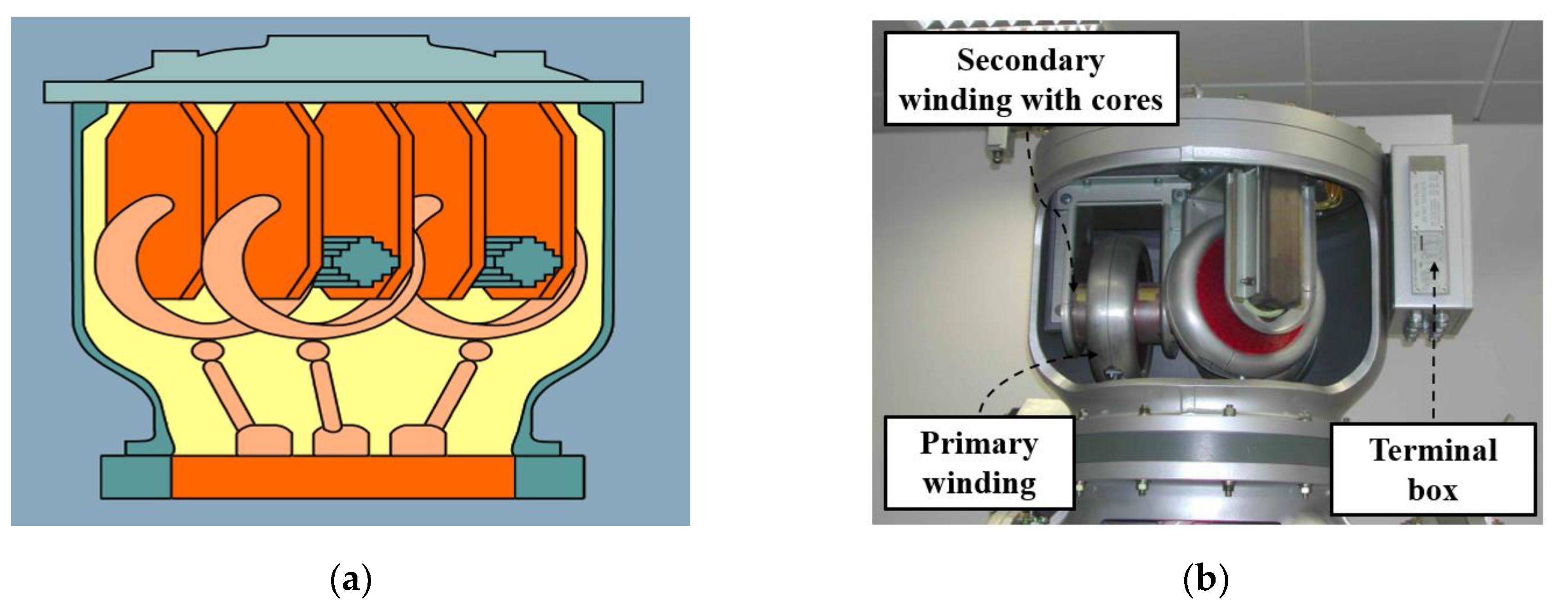
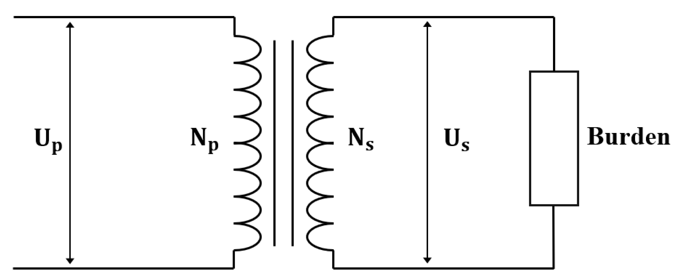
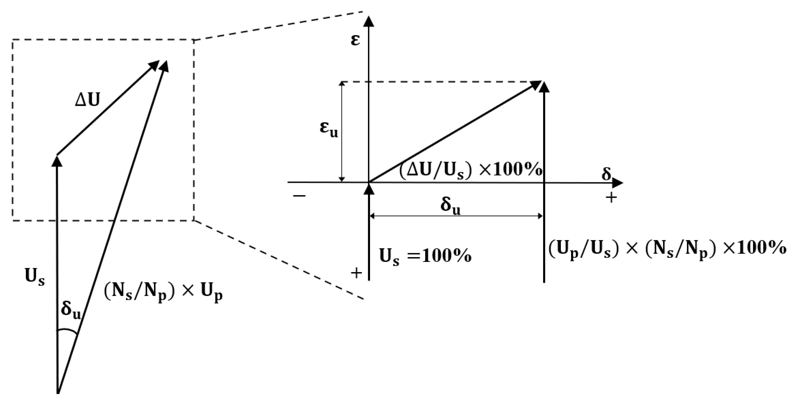
3.1. Voltage Transformers

In high-voltage substations, the VTs used for voltage measurement are IVTs and CVTs. CVTs are mainly used for single-phase voltage measurement in AISs. In contrast, IVTs are applied in GISs, which have a compact structure and high insulation performance compared to AISs. IVTs are installed in an enclosure filled with SF6 as shown in Figure 2. VT are installed for all three phases and need to be designed with specific transformation ratios such as 154 k V / 3 : 110 V / 3 for signal phase/ground operation in the case of a 170 kV three-phase system [52,53].
IVTs operate based on the principle of electromagnetic induction. The primary winding is directly connected to the primary conductor, inducing a magnetic field in the core and induces voltage in the secondary winding. Figure 3 shows the configuration of an IVT.
The secondary voltage based on the ratio of primary and secondary turns can be expressed as following Equation (1):
U s = N s N p × U p U
where U p and U s are the primary and secondary voltages of the IVT and N p and N s are the primary and secondary turns of the VT. U represents the voltage drop due to the winding resistance and leakage reactance of the actual IVT.
In the design of IVTs, the magnitude and phase error of the primary voltage are crucial factors in determining the accuracy class of the IT in measurements. Voltage ratio error and phase displacement can be estimated. Figure 4 shows the vectors of three voltages in a typical VT.
Herein, ε u is the ratio error of the voltage, and δ u is the phase displacement between the primary and secondary voltages. When the secondary voltage is higher than the rated transformation ratio, ε is positive, and when the phase of the secondary voltage leads the phase of the primary voltage, the phase displacement is expressed as positive.
The rated secondary voltage for the first primary voltage of an IVT and the accuracy class are defined by IEC 61869-3. According to the international standard, the rated secondary voltage is output as an analog signal through the terminal box, typically 110 V or 100 V [33]. All ITs have an accuracy class designation through accuracy tests to ensure compliance with the design rating. The accuracy class is determined based on the characteristics of voltage ratio error and phase displacement. The voltage ratio error defined in the IEC 61869-3 standard is expressed in Equation (2), as follows:
ε u = K r U s U p U p × 100 [ % ]
The error for phase displacement is expressed in Equation (3), as follows:
δ u = φ u s φ u p
where ε u is the voltage ratio error, δ u is phase displacement, U p and U s represent the primary and secondary voltages of the VT, φ u p and φ u s are the primary and secondary phase angles of the PT, and K r is the rated transformation ratio.
The accuracy class required for VTs as required by the standard is presented in Table 2. The voltage ratio error and phase displacement of VTs at the rated frequency should not exceed the values specified in Table 2 for all voltages and burdens within the range of 80% to 120% of the rated voltage.

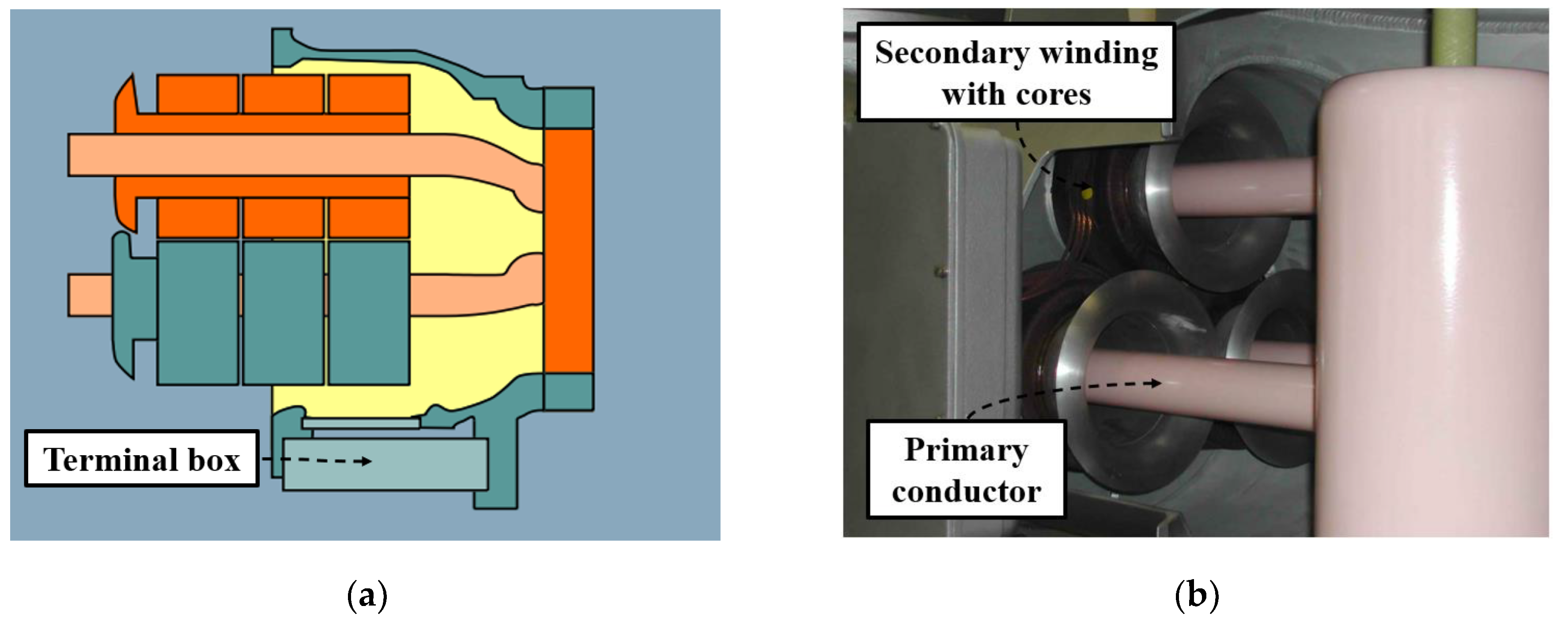
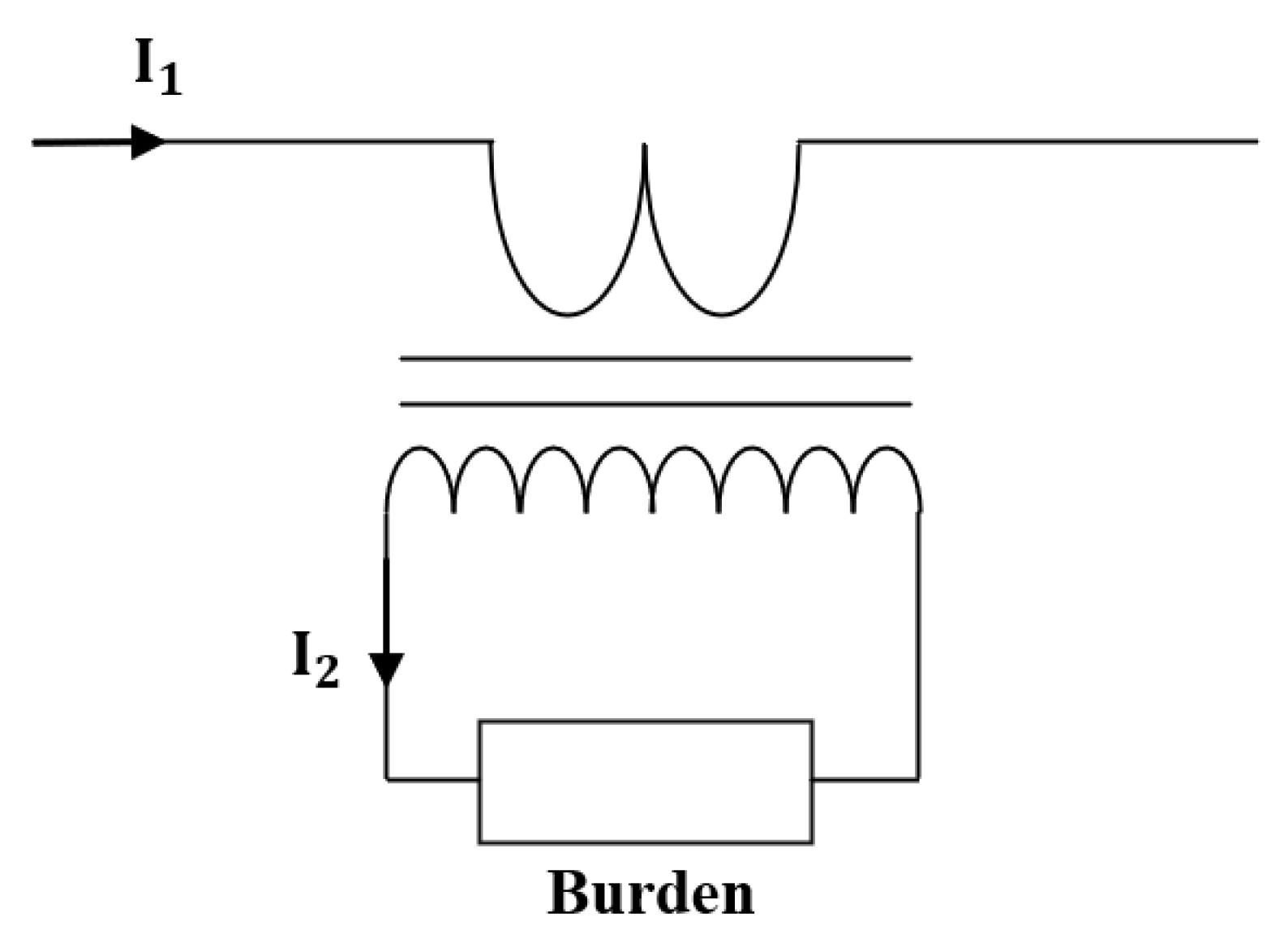
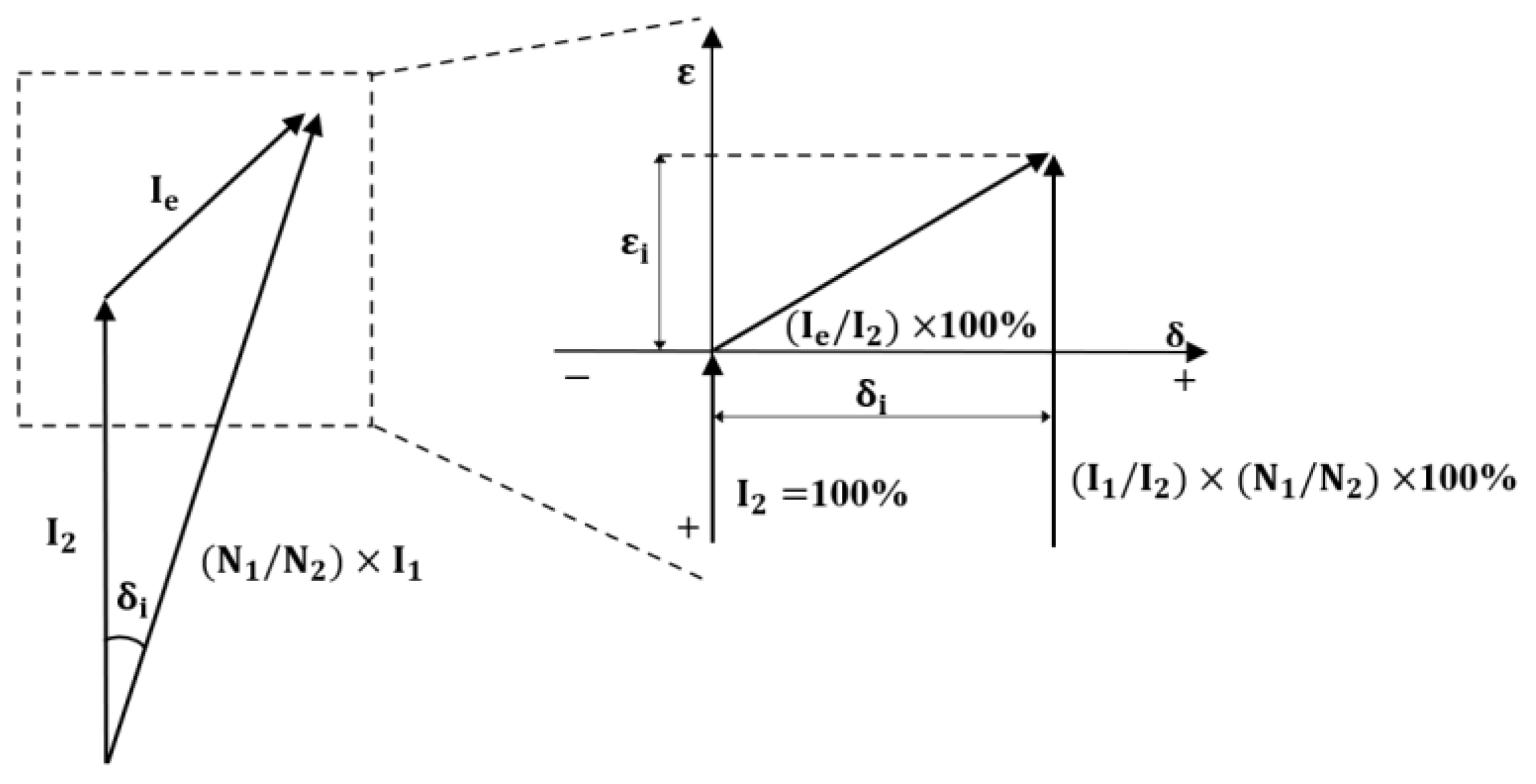
3.2. Current Transformers

ICTs are commonly used in GISs that employ the conductor as the primary winding. The design consists of a high-permeability iron core and copper windings. ICTs of GISs are installed within the GIS enclosures. The details of an ICT are shown in Figure 5. The size of the enclosure in GIS bays is influenced by the requirements of metering and protection, considering factors such as the number and size of cores based on the demands of the core.
ICTs operate based on the principle of electromagnetic induction and have the primary conductor serving as the transformer’s primary winding. The configuration of an ICT is shown in Figure 6.
The secondary current, based on the ratio of primary and secondary turns, can be expressed in Equation (4), as follows:
I 2 = N 1 N 2 × I 1 I e
where I 1 and I 2 are the primary and secondary currents of the ICT and N 1 and N 2 are the primary and secondary turns of the ICT. Since the primary winding of the ICT is the primary conductor, the number of turns is 1. Furthermore, I e is excitation current, causing phase and ratio errors due to loss current from the iron cores and magnetizing components.
Reproducing errors in CT manufacturing is crucial. Current ratio error and phase displacement can be estimated. Figure 7 shows the vectors of the three currents in a typical CT.
Herein, the secondary current of I 2 is chosen as the reference vector and set to 100%. ε i is the voltage ratio error, and δ i is the phase displacement between the primary and secondary voltages. When the secondary current is higher than the rated transformation ratio, it is positive, and when the phase of the secondary current leads the phase of the primary current, the phase displacement is expressed as positive.
The rated secondary voltage for the primary voltage of an ICT and the accuracy class are defined by IEC 61869-2. For a CT, the rated secondary current should be 5 A or 1 A [35]. The accuracy class of a CT is determined based on the characteristics of current ratio error and phase displacement. The ratio error and phase displacement of current, as defined by IEC 61869-2, are expressed in Equation (5) as follows:
ε i = K r I 2 I 1 I 1 × 100 [ % ]
The error for phase displacement is expressed in Equation (6), as follows:
δ i = φ i 2 φ i 1
where ε i is the current ratio error, δ i is the phase displacement, I 1 and I 2 are the CT’s primary current and secondary current, and φ i 1 and φ i 2 are the primary and secondary phase angles of the CT.
The accuracy class required by IEC 61869-2 for a CT is shown in Table 3. The current ratio error and phase displacement of the CT should not exceed the values specified in Table 3 at 5%, 20%, 100%, and 120% of the rated primary current under rated frequency and burden.

4. Non-Conventional Instrument Transformers

In recent years, voltage and current have become very important measurements in high voltage systems for control and protection purposes due to increasing power demand and expending capacity of power facilities [55,56]. Traditional iron-core type IVTs and ICTs face limitations such as insulation deficiencies, mechanical strength issues, and seismic vulnerabilities in high-voltage environments. Furthermore, the effects of impulses from events such as opening and closing surges and external thunderstorms affect the device through electrostatic induction or electromagnetic flow effects [57,58]. Consequently, there has been a great deal of research conducted to introduce new approaches to enhance the reliability and stability of high-voltage measurement devices [56,59,60,61,62,63].
This paper focuses on NCITs to replace ITs in GISs to achieve a smaller, lighter, greener, and digitalization of substations [64]. NCITs are broadly categorized into EITs, based on IEC 60044-7 and 8, and LPITs, based on IEC 61869-10 and 11. The beginning of the NCIT was the decentralized transmission of voltage and current signals to substation control rooms via fiber optic connections, coinciding with the introduction of IEC 61850 9-2. Furthermore, inconsistencies in signal communication systems among manufacturers have led to various technical research into standalone merging units (SAMUs) to ensure interoperability and facilitate the connection and correct operation of individual devices. [65,66].
Additionally, EITs and LPITs are limited to relatively low output power (within a few VA), which allows them to connect directly to data acquisition devices, reducing unnecessary adapters and improving accuracy. Smart grids and digitalized substations particularly in the context of decentralized power sources such as renewable energy have been found new applications of EIT and LPIT by leveraging these advantages such as where they can operate in a limited footprint [67].

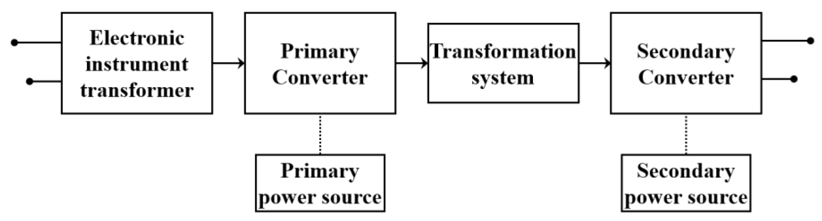
4.1. Electronic Instrument Transformers (EITs)

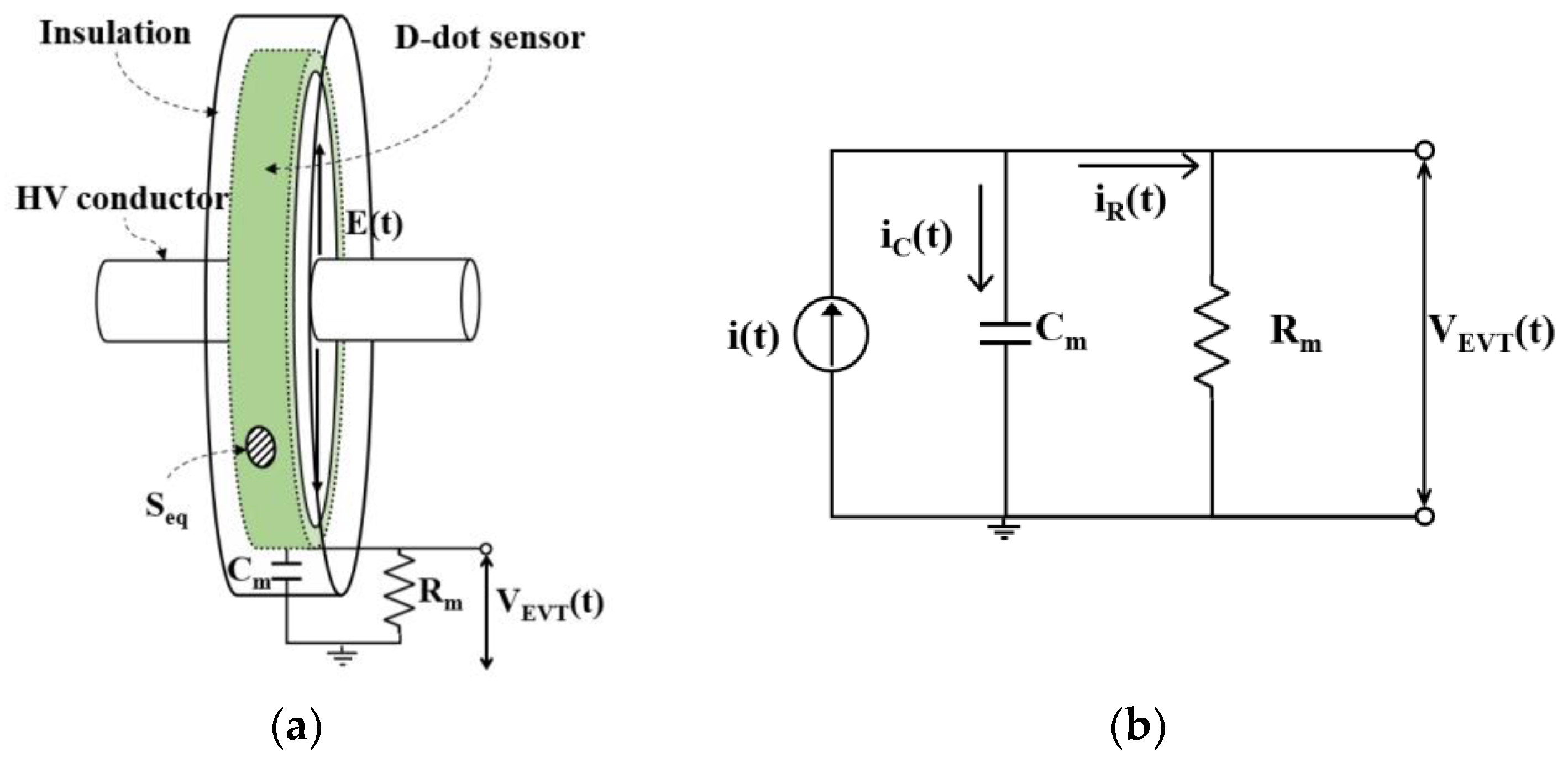
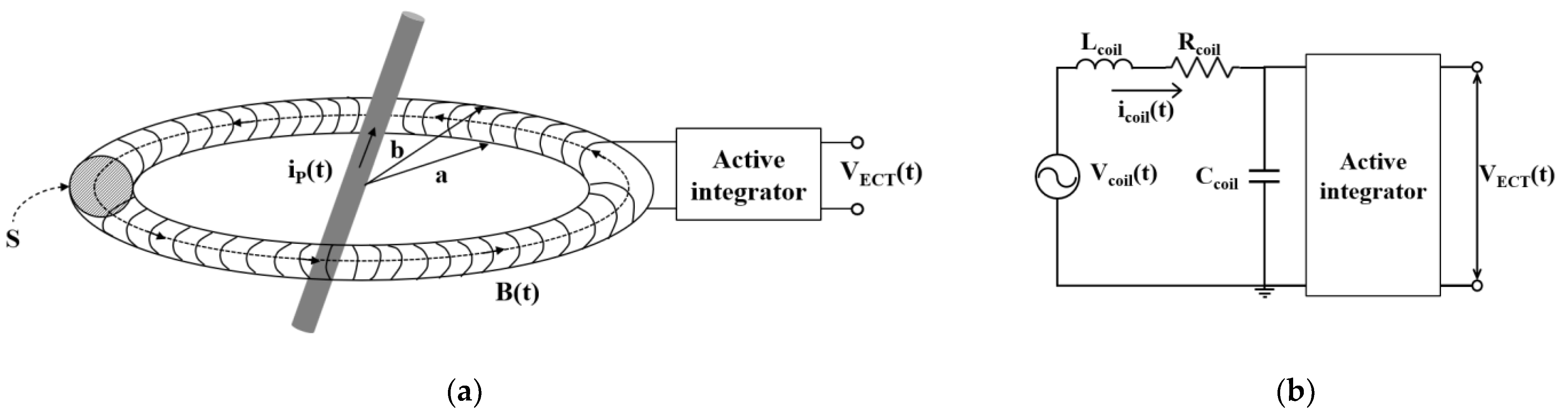
4.1.1. Principle and Structures of EVTs and ECT

IVTs installed in GISs have a direct electrical connection between the primary high and secondary low voltages, making them susceptible to insulation breakdown during operation due to transients. Furthermore, the LC resonance phenomenon can occur when a breaker opens at the termination of the main system [68]. This phenomenon involves a combination of capacitive reactance, caused by the charge capacity between each pole and ground, and inductive reactance, induced by the voltage in the main system [69]. When these factors are combined in series, it can result in high commercial frequency overvoltage, potentially leading to insulation breakdown in the GIS. To address this issue, EVTs according to IEC 60044-7 were introduced. An EVT is designed for voltage measurement while maintaining electrical isolation between the high- and low-voltage sides based on the D-dot principle using Gaussian laws [70,71]. Figure 8 shows the structure and equivalent circuit of a D-dot sensor applied to a typical EVT.
Equation (7) from the equivalent circuit is expressed as Equation (8):
i t = i C t + i R ( t )
ε d E ( t ) d t × S e q = C m d V ( t ) d t + V ( t ) R m
where ε is the permittivity of the insulation, such as an epoxy insulator; E ( t ) is the intensity of the incident electric field; S e q is the equivalent area enclosed by the closed surface of the sensing electrode; C m is the capacitance between the sensing electrode and ground; and R m is the output resistance of the sensing electrode. The output of the EVT can be expressed as Equation (9) by adjusting the output resistance of the sensing electrode or the impedance of measurement device. If R m is lower than a few kΩ or the impedance of the measurement device is low, the output of the EVT becomes proportional to the first derivative value of the induced electric field or magnetic flux density [71,72].
V t = R m × S e q × ε d E ( t ) d t = R m × S e q × d D ( t ) d t
Substation digitization has adopted air-core Rogowski-coil current sensors (RCS) in the GIS in accordance with 61850-9-2 due to the limitation of ICTs [73]. Both RCSs and ICTs operate based on Faraday’s law. However, their differences are in their saturation characteristics. Unlike ICTs with iron cores that experience magnetic saturation, air-core RCSs remain unsaturated even under transient conditions such as short circuits or ground faults. This unique characteristic ensures a linear output [13,74]. Figure 9 shows the structure and equivalent circuit of an RCS.
Once a large current is applied to the HV conductor, the magnetic flux in the air-core RCS links with it, inducing a current in the RCS coil. The induced secondary current in the RCS coil leads the primary current in the HV conductor by 90 degrees. Therefore, the voltage induced in the coil is expressed as the Equation (10):
V c o i l t = M d i p t d t
where M is the mutual inductance between the primary conductor and RCS, and is expressed as following Equation (11):
M = μ 0 N ( b a ) 2 2
where, μ 0 is the permeability of air, N is the number of turns of the coil, a is the inner radius of the coil, and b is the outer radius of the coil.
Due to the internal elements within the RCS winding, such as mutual and self-inductance, self-capacitance, and self-resistance, the output voltage of the RCS is determined through the R–L voltage drop, as expressed in the following Equation (12) [75].
V R C S t = M d i p t d t L c o i l d i c o i l t d t R c o i l · i s ( t )
where L C o i l is the self-inductance of the RCS and R C o i l is the self-resistance of the RCS. Due to the derivative characteristics of the RCS, the output signal must be connected to converters for the restoration of the signal to its original form.
Due to the susceptibility of RCSs to external electric fields, many studies have been conducted on optimizing the sensor structures to enhance output characteristics and minimize external interference. L. Ferković and colleagues [76] conducted simulations to analyze the impact of the RCS output by examining the mutual inductance between the high-voltage conductor and the RCS coils. The analysis considered various aspects of RCS structure, such as winding thickness, spacing, and the position of the conductor. While the influence of the position of the high-voltage conductor and the RCS was found to be insignificant, approximately 1%, the winding structure of the RCS was identified as having a significant impact. Specifically, maintaining a constant winding density was highlighted as a substantial contributor to the power output. Another study conducted by M. Shafiq and colleagues [77] involved deriving optimal geometrical parameters through principal analysis of RCS and presenting key design aspects to be considered in current measurement using RCS.
Through these studies on current measurement using RCSs, a high-precision CT for application in digital substations is proposed. This CT is intended to replace ICTs, which are traditionally designed, fabricated, and installed separately for measurement and protection purposes due to issues related to flux saturation with a single RCS.
Figure 10 shows a block diagram of a typical EIT. According to IEC 60044, the converters such as IC that use external power can be employed to generate suitable outputs that satisfy the accuracy class, since primary and secondary converters are available, and an external power source for each converter is connected. The EIT, therefore, allows a digital output [78].

4.1.2. Accuracy of EVTs and ECTs

The voltage and current ratio error ε are calculated in the rated frequency component using Equation (13), and the phase error φ e , which represents the amount by which the secondary voltage and current are out of phase with the primary voltage and current, is calculated using Equation (14).
ε = K n U S U P U P × 100 [ % ]
φ e = φ S φ P φ 0 n + 2 π f t d n
where K n is the rated transformation ratio, U P represents the root mean square (RMS) values of the actual primary values (voltage and current), U S is the RMS value of the actual secondary voltage measured by the EVT and ECT, φ P is the primary phase measured by the EVT and ECT, φ S is the secondary phase measured by the EVT and ECT, φ 0 n is the rated phase offset, and t d n is the rated delay time.
The accuracy classes for EITs in measurement are specified as 0.1–0.2–0.5–1–3. The ratio error and phase error for each accuracy class of EVT and ECT are specified in Table 4 and Table 5. As shown in Table 5, limits of errors for ECTs are only specified in the accuracy classes of 0.1, 0.2, 0.5, and 1, not the accuracy class of 3. These classes are determined based on the tolerance range of the rated voltage and current and the standard reference ranges of the burden. Each ratio error and phase error must comply with ambient temperature, the rated frequency, the rated burden, the rated auxiliary power, and a lagged power factor of 0.8.

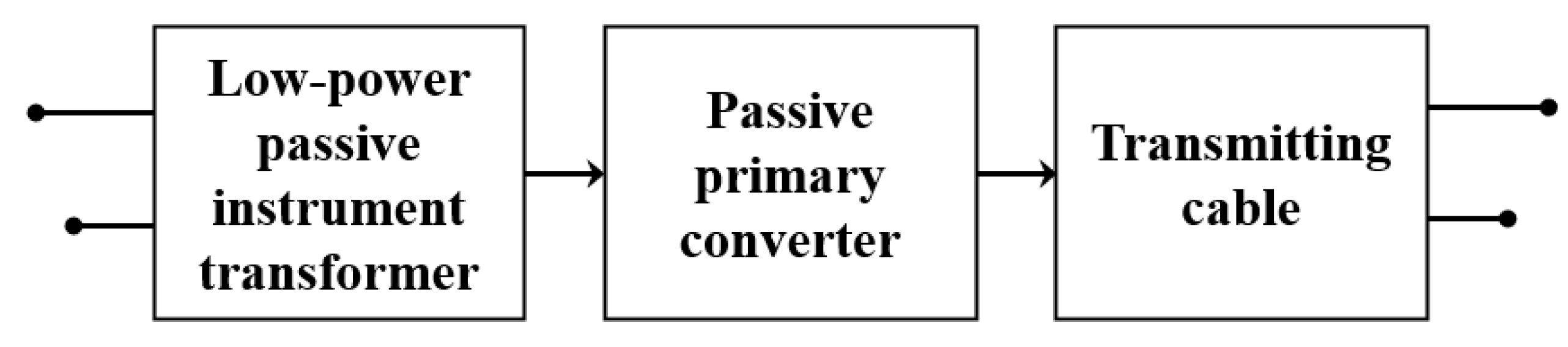
4.2. Low-Power Passive Instrument Transformer (LPITs)

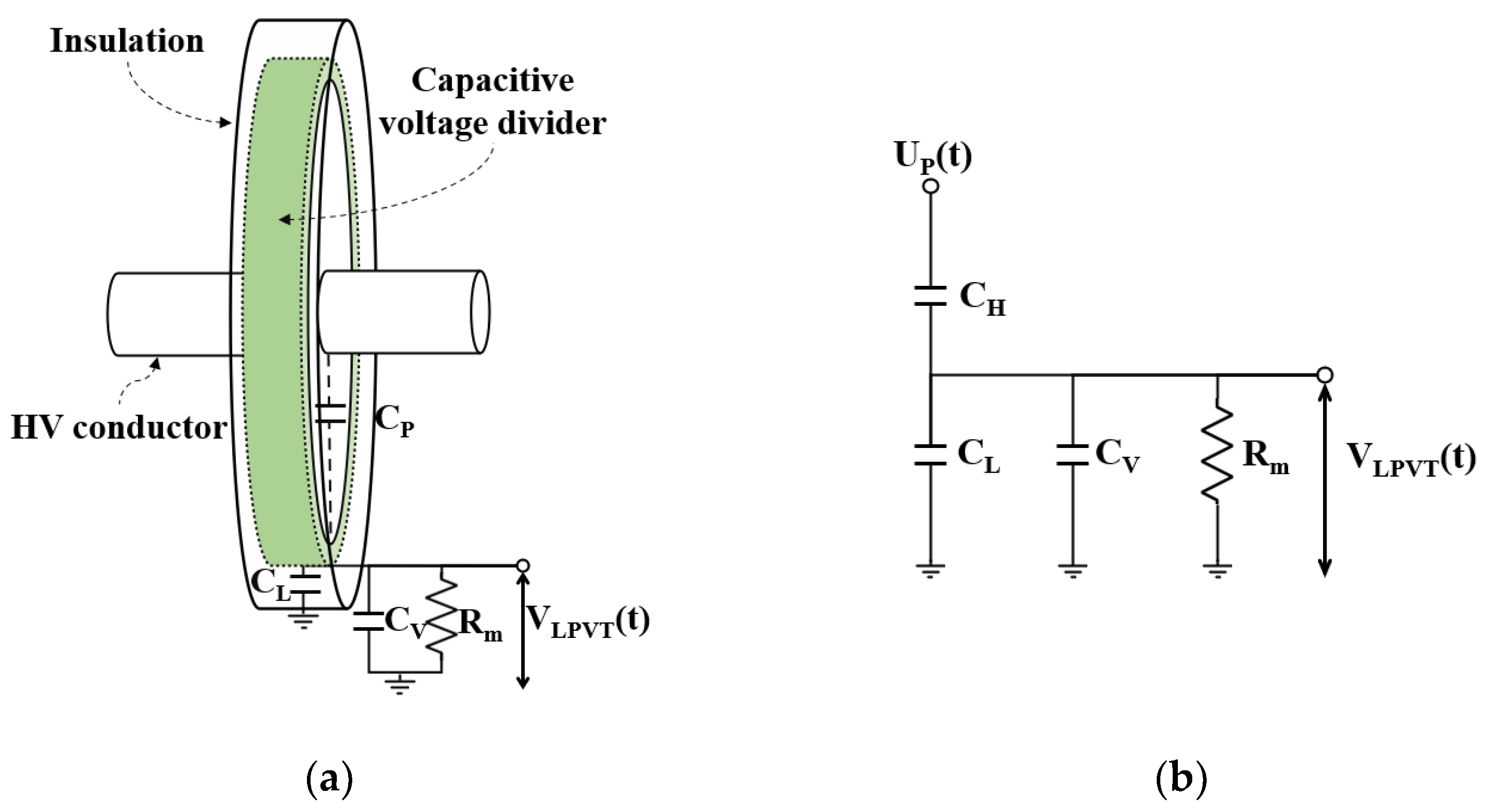
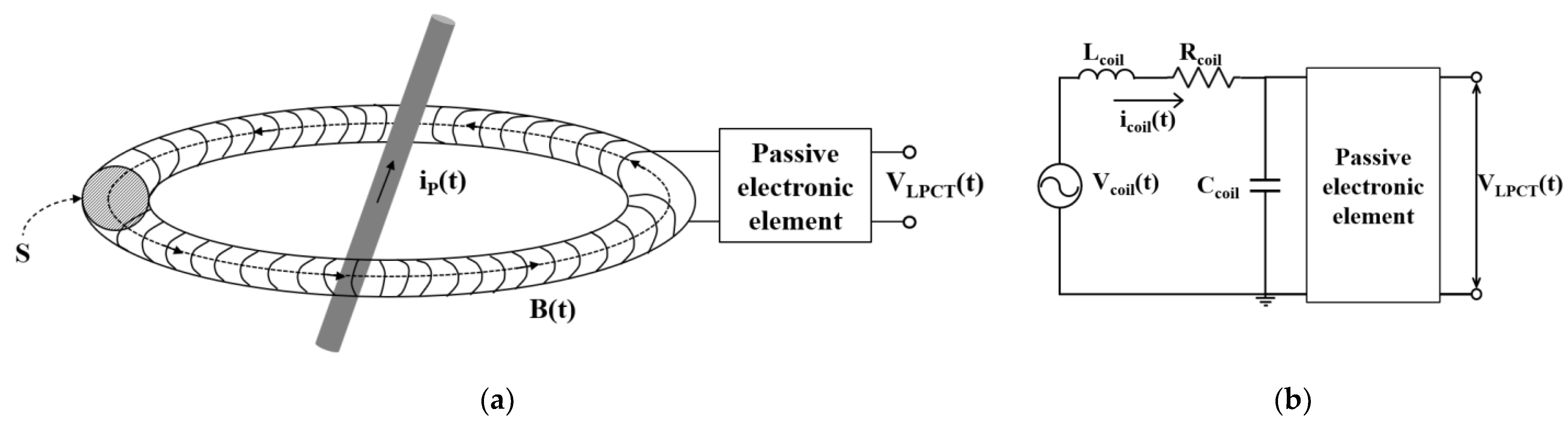
4.2.1. Principle and Structures of LPVTs and LPCTs

An LPVT is based on the voltage divider principle rather than the D-dot method of measuring derivative signals used in EVTs. The voltage divider principle, which can be employed in an LPVT, is categorized into four dividers in accordance with IEC 61869-11: a resistive voltage divider (R-divider), a capacitive voltage divider (C-divider), a resistive-capacitive voltage divider (RC-divider), and an RC-divider with a passive integrator [25]. The R-divider, which is directly connected to the primary conductor, is typically utilized for low-voltage applications. In contrast, the C-divider and RC-divider, which facilitate non-contact measurement, are employed for high-voltage measurements. Those dividers, which can secure stability by electrically separating the high- and low-voltage sides, are mainly applied to the LPVT [79,80,81]. Figure 11 shows the conceptual structure and equivalent circuit of a typical LPVT with a capacitive voltage divider (CVD) principle based on the C-divider.
The LPVT’s output can be expressed as the following Equation (15) [82].
V L P V T ( t ) = C H C H + C L + C V × U P ( t )
An LPVT with a CVD consists of a high-voltage stray capacitor C H between a high-voltage conductor and the CVD electrode installed at a distance, along with a low-voltage capacitor C L between the CVD electrode and ground [83]. In addition, a controlling capacitor C V for the transformation ratio defined in IEC 61869-11 is connected in parallel with C L . The output impedance, a resistor of 2 MΩ and a capacitor of 50 pF, must be installed in parallel to satisfy the rated burden defined in IEC 61869-1.
LPCTs are essentially constructed on the same principle as ECTs, utilizing a Rogowski-coil current sensor. An RCS has a non-magnetic air core, ensuring a linear and non-saturated output. However, the mutual coupling between the primary conductor and an RCS’s winding is significantly smaller than that of an ICT. As a result, the output power is also low, making LPCTs suitable for microprocessor-based devices with high input impedance. LPCTs differ from ECTs in that they are required by the IEC requirement to provide only analog outputs and must be based on passive technology with no active electronic components [78]. Figure 12 shows the structure and equivalent circuit of an LPCT.
According to IEC 61869-10, no active electronic components can be connected to an LPCT, in contrast to an ECT. Due to the characteristics of RCSs, the output signal leads the primary current by 90 degrees. Therefore, a phase displacement of 90 degrees is considered [84,85,86,87]. Figure 13 shows a block diagram of a typical LPIT. Unlike the EIT described earlier, derivative output signals are not within the scope of an LPIT according to IEC 61869-10 and 11, and the LPIT should operate without any active electronic components. Therefore, since it does not contain any active electronics such as additional IC, it does not require an additional power supply, allowing for very stable and accurate measurements over a wide range [88]. As a result, LPVTs must be designed based on the voltage divider principle compared to the D-dot principle of EVTs, and LPCTs apply the same approach as ECTs but differ in that they allow for derivative output signals. In addition, LPITs have a new procedure called output correction.

4.2.2. Accuracy of LPVTs and LPCTs

Calculation of the ratio error and phase error of an LPIT is similar to that of an EIT, but it is correctable because it does not use any active electronic component. The ratio error can be corrected by applying a correction factor in the range of 0.900 to 1.100, and the phase error can be corrected by applying a phase offset correction in the range of ±300 min (5 degrees). The corrected ratio error and corrected phase error are calculated by Equations (16) and (17), respectively.
ε c o r U = C F U · K r · V L P I T U P U P × 100 [ % ]
φ e c o r = φ L P I T φ P φ c o r φ o
where C F U is the correction factor, K r is the rated transformation ratio, U P is the primary high voltage and high current, V L P I T is the secondary output voltage measured by LPVT and LPCT, φ P is the phase angle of the primary high voltage, φ L P I T is the LPVT and LPCT’s phase angle, and φ c o r φ o is the corrected phase offset.
The standard accuracy classes for LPITs are the same as for EITs: 0.1–0.2–0.5–1–3, and must be satisfied with a tolerance among 80%, 100%, and 120% of the rated voltage for LPVTs and 5%, 20%, 50%, 100%, and 120% of the rated voltage for LPCTs. Table 6 and Table 7 shows limits of error for LPVTs and LPCTs, respectively. Ratio errors and phase errors must be satisfied when the rated frequency range and ambient temperature range are within the reference range, and when connected within ±5% of the resistive part of the rated burden and between 0% and 100% of the capacitive part of the rated burden.
NCITs, including both EITs and LPITs, have various pros and cons compared to conventional IT, and the decision of which device to install and use depends on site conditions. When the NCIT is applied to the GIS with a rated voltage of 72.5 kV, it is possible to reduce the size by 33% in length, 23% in height per bay of a three-phase-in-one-enclosure type of GIS, as shown in Figure 14. Additionally, since the amount of SF6 is reduced by 15% in terms of volume, it is effective for improving the eco-friendliness of power equipment. Applying NCIT can reduce the size of the GIS by about 5–10% [13,69,80,83]. Moreover, the amount of copper wires in a conventional IT can be significantly reduced, helping to reduce potential failure factors and improve reliability.

5. Conclusions

This paper aimed to explore the development of technologies and methods for measuring instruments in GISs to deepen our understanding of the capabilities of CITs and NCITs. Significant advancements in the field of ITs have been observed in response to the evolving requirements of high-voltage substations. Conventional ITs, such as IVTs and ICTs, have been instrumental in power systems but face challenges related to size, weight, insulation, and accuracy, particularly in GISs. The utilization of SF6 in GISs, while enhancing insulation performance, has led to issues such as magnetic saturation in conventional transformers. To address these challenges in the era of digital substations, NCITs have emerged as a viable solution. EITs and LPITs conforming to standards such as IEC 60044-7 and 8 and 61869-10 and 11 offer alternatives to conventional ITs.
  • EITs, using Rogowski coils, offer excellent accuracy and dynamics but struggle with EMC and disturbances, limiting their use. LPIT types such as LPVTs and LPCTs aim to solve these issues. LPVTs apply the voltage divider principle, and LPCTs use Rogowski coils or an iron core, both ensuring stable, accurate measurements without active electronic components.
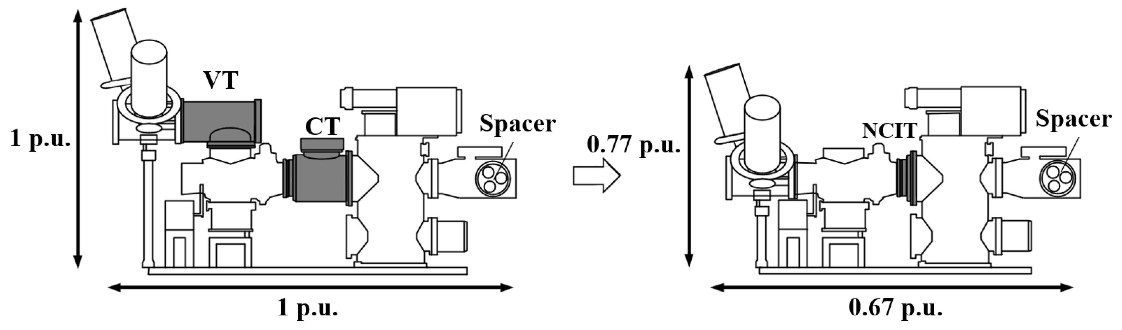
  • The shift from IEC 60044 to IEC 61869 marks a significant change in IT standards, with LPITs driving the miniaturization and digitalization of GISs. When applied to a 72.5 kV GIS, an LPIT offers notable reductions in size, weight, and environmental impact, proving to be a sustainable and efficient choice for contemporary power systems.
  • Given current trends and progress, choosing between conventional ITs and NCITs, especially LPITs, hinges on specific site needs. In the evolving power industry, NCITs’ role in improving high-voltage substations’ reliability, stability, and environmental sustainability is becoming increasingly important.
  • Despite existing challenges, including commercial adoption, EMC, susceptibility to external disturbances, and the need for standardization, it is imperative that ongoing research, efforts towards standardization, and collaboration within the industry continue. These steps are crucial for overcoming these obstacles and fully harnessing the potential of NCITs in contemporary power systems.
At present, several of the technologies and methods discussed are still in the laboratory research stage, facing challenges that need to be addressed, such as the effects of EMC, temperature variations, and external disturbances. Despite these challenges, continuous research and advancements have been achieved in the field of measurement applications over the past few decades. This paper highlights the potential of NCITs in modern power systems, especially in terms of fostering collaborative initiatives among industry stakeholders.

Author Contributions

Conceptualization, D.-E.K. and S.-W.K.; methodology, G.-S.K.; validation, S.-W.K.; formal analysis, G.-Y.L.; investigation, D.-E.K.; resources, G.-Y.L.; data curation, S.-W.K. and G.-Y.L.; writing—original draft preparation, D.-E.K.; writing—review and editing, G.-S.K. All authors have read and agreed to the published version of the manuscript.

Funding

This work was supported by the Technology Innovation Program (No. 20010965, Development of Electronic Current Voltage Transformer and Spacer based on Eco-friendly Solid Insulation) funded by the Ministry of Trade, Industry & Energy (MOTIE) and Korea Evaluation Institute of Industrial Technology (KEIT) of the Republic of Korea.

Conflicts of Interest

The authors declare no conflicts of interest.

References

  1. IEC 60044-1; Instrument Transformers—Part 1: Current Transformers. International Electrotechnical Commission: Geneva, Switzerland, 1996.
  2. IEC 60044-2; Instrument Transformers—Part 2: Inductive Voltage Transformers. International Electrotechnical Commission: Geneva, Switzerland, 1997.
  3. Gómez Sandoval, K.Y.; Marriaga Márquez, I.A.; Silva Ortega, J.I.; Grimaldo Guerrero, J.W.; Hernandez Herrera, H. Bibliometric review of emerging technologies in Gas Insulated Substations SF6. In Proceedings of the Development of Engineering and Innovation in the Scenarios of the 4th Industrial Revolution (EXPOTECNOLOGIA 2020), Cartagena, Colombia, 4–6 November 2020. [Google Scholar] [CrossRef]
  4. Riechert, U.; Holaus, W. Ultra high-voltage gas-insulated switchgear—A technology milestone. Eur. Trans. Electr. Power 2012, 22, 60–82. [Google Scholar] [CrossRef]
  5. Thummapal, D.; Kothari, S.; Thirumalai, M. Emerging Technologies in High Voltage Gas Insulated Switchgear-Clean Air GIS and NCIT. In Proceedings of the 2019 International Conference on High Voltage Engineering and Technology (ICHVET), Hyderabad, India, 7–8 February 2019. [Google Scholar] [CrossRef]
  6. Bolin, P. Gas-Insulated Substations. In Electric Power Substations Engineering, 3rd ed.; McDonald, J.D., Ed.; CRC Press: Boca Raton, FL, USA, 2012; pp. 2.1–2.19. ISBN 9781315213910. [Google Scholar]
  7. Haddad, A.; Warne, D.F. Advances in High Voltage Engineering, 1st ed.; The Institution of Engineering and Technology: Stevenage, UK, 2004; pp. 37–73. ISBN 9781849190381. [Google Scholar]
  8. Bassan, F.R.; Rosolem, J.B.; Floridia, C.; Aires, B.N.; Peres, R.; Aprea, J.F.; Nascimento, C.A.M.; Fruett, F. Power-over-Fiber LPIT for Voltage and Current Measurements in the Medium Voltage Distribution Networks. Sensors 2021, 21, 547. [Google Scholar] [CrossRef]
  9. Resende, D.F.; Silva, L.R.M.; Nepomuceno, E.G.; Duque, C.A. Optimizing Instrument Transformer Performance through Adaptive Blind Equalization and Genetic Algorithms. Energies 2023, 16, 7354. [Google Scholar] [CrossRef]
  10. Thomas, R.; Vujanic, A.; Xu, D.Z.; Sjodin, J.E.; Salazar, H.R.M.; Yang, M.; Powers, N. Non-Conventional Instrument Transformers Enabling Digital Substations for Future Grid. In Proceedings of the IEEE Power Engineering Society Transmission and Distribution Conference, Dallas, TX, USA, 3–5 May 2016. [Google Scholar] [CrossRef]
  11. Kim, D.E.; Kim, N.H.; Kim, S.G.; Kim, S.W.; Kil, G.S. Development of Combined Instrument Transformer for Gas-Insulated Switchgears. J. Korean Soc. Railw. 2023, 26, 268–276. [Google Scholar] [CrossRef]
  12. Daboul, M.; Orságová, J.; Jurák, V.; Vrtal, M. Testing Rogowski Coils with Merging Units for Smart Grids. Energies 2023, 16, 7323. [Google Scholar] [CrossRef]
  13. Mingotti, A.; Betti, C.; Peretto, L.; Tinarelli, R. Simplified and Low-Cost Characterization of Medium-Voltage Low-Power Voltage Transformers in the Power Quality Frequency Range. Sensors 2022, 22, 2274. [Google Scholar] [CrossRef] [PubMed]
  14. Frigo, G.; Agustoni, M. Characterization of a Low Power Instrument Transformer with Digital Output in Low-Inertia Power Systems. In Proceedings of the 2022 International Conference on Smart Grid Synchronized Measurements and Analytics (SGSMA), Split, Croatia, 24–26 May 2022. [Google Scholar] [CrossRef]
  15. Hunt, R.; Flynn, B.; Smith, T. The Substation of the Future: Moving toward a Digital Solution. IEEE Power Energy Mag. 2019, 17, 47–55. [Google Scholar] [CrossRef]
  16. IEC 61850-9-2; Communication Networks and Systems for Power Utility Automation—Part 9-2: Specific Communication Service Mapping (SCSM)—Sampled Values over ISO/IEC 8802-3. International Electrotechnical Commission: Geneva, Switzerland, 2011.
  17. IEC 60044-7; Instrument Transformers—Part 7: Electronic Voltage Transformers. International Electrotechnical Commission: Geneva, Switzerland, 1999.
  18. IEC 60044-8; Instrument Transformers—Part 8: Electronic Current Transformers. International Electrotechnical Commission: Geneva, Switzerland, 2002.
  19. Chen, Q.; Li, H.B.; Huang, B.X. An innovative combined electronic instrument transformer applied in high voltage lines. Measurement 2010, 43, 960–965. [Google Scholar] [CrossRef]
  20. Saitoh, M.; Kimura, T.; Minami, Y.; Yamanaka, N.; Maruyama, S.; Nakajima, T.; Kosakada, M. Electronic instrument transformers for integrated substation systems. In Proceedings of the IEEE/PES Transmission and Distribution Conference and Exhibition, Yokohama, Japan, 6–10 October 2002. [Google Scholar] [CrossRef]
  21. Tarmizi, A.I.; Rotaru, M.D.; Sykulski, J.K. Electromagnetic compatibility studies within smart grid automated substations. In Proceedings of the 2014 49th International Universities Power Engineering Conference (UPEC), Cluj-Napoca, Romania, 2–5 September 2014. [Google Scholar] [CrossRef]
  22. Liu, B.; Tong, Y.; Deng, X.P.; Wan, G. The electromagnetic compatibility research of electronic transformer under simulated complex environment. In Proceedings of the 2014 International Conference on Power System Technology, Chengdu, China, 20–22 October 2014. [Google Scholar] [CrossRef]
  23. Liu, G.; Zhao, P.; Qin, Y.; Zhao, M.; Yang, Z.; Chen, H. Electromagnetic Immunity Performance of Intelligent Electronic Equipment in Smart Substation’s Electromagnetic Environment. Energies 2020, 13, 1130. [Google Scholar] [CrossRef]
  24. IEC 61869-10; Instrument transformers—Part 10: Additional Requirements for Low-Power Passive Current Transformers. International Electrotechnical Commission: Geneva, Switzerland, 2017.
  25. IEC 61869-11; Instrument transformers—Part 11: Additional Requirements for Low Power Passive Voltage Transformers. International Electrotechnical Commission: Geneva, Switzerland, 2017.
  26. Moreno, A.; Gil, C.; Santiago, J.R. IEC 61869-10 and IEC 61869-11 Passive Sensors and their Interface with IEDS. In Proceedings of the CIRED 2021—The 26th International Conference and Exhibition on Electricity Distribution, Online Conference, 20–23 September 2021. [Google Scholar] [CrossRef]
  27. Milovac, P.; Javora, R.; Skendzic, V. Sensor Technology in a Medium-Voltage Switchgear for the US Market Applications. CIRED—Open Access Proc. J. 2017, 2017, 432–435. [Google Scholar] [CrossRef]
  28. Shotter, G.F. A new null method of testing instrument transformers, and its application. J. Inst. Electr. Eng. 1930, 68, 873–888. [Google Scholar] [CrossRef]
  29. Robinson, L.T. Electrical measurements on circuits requiring current and potential transformers. Proc. Am. Inst. Electr. Eng. 1909, 28, 981–1015. [Google Scholar] [CrossRef]
  30. Djokić, B.V.; Parks, H.; Wise, N.; Naumović-Vuković, D.; Škundrić, S.P.; Žigić, A.D.; Polužanski, V. A comparison of two current transformer calibration systems at NRC Canada. IEEE Trans. Instrum. Meas. 2016, 66, 1628–1635. [Google Scholar] [CrossRef]
  31. IEC 61869-1; Instrument Transformers—Part 1: General Requirements. International Electrotechnical Commission: Geneva, Switzerland, 2023.
  32. IEC 60044-5; Instrument Transformers—Part 5: Capacitor Voltage Transformers. International Electrotechnical Commission: Geneva, Switzerland, 2011.
  33. IEC 61869-3; Instrument Transformers—Part 3: Additional Requirements for Inductive Voltage Transformers. International Electrotechnical Commission: Geneva, Switzerland, 2011.
  34. IEC 61869-5; Instrument Transformers—Part 5: Additional Requirements for Capacitor Voltage Transformers. International Electrotechnical Commission: Geneva, Switzerland, 2011.
  35. IEC 61869-2; Instrument Transformers—Part 2: Additional Requirements for Current Transformers. International Electrotechnical Commission: Geneva, Switzerland, 2012.
  36. IEC 60044-6; Instrument Transformers—Part 6: Requirements for Protective Current Transformers for Transient Performance. International Electrotechnical Commission: Geneva, Switzerland, 1992.
  37. IEC 60044-3; Instrument Transformers—Part 3: Combined Transformers. International Electrotechnical Commission: Geneva, Switzerland, 1980.
  38. IEC 61869-4; Instrument Transformers—Part 4: Additional Requirements for Combined Transformers. International Electrotechnical Commission: Geneva, Switzerland, 2013.
  39. IEC 61869-6; Instrument Transformers—Part 6: Additional General Requirements for Low-Power Instrument Transformers. International Electrotechnical Commission: Geneva, Switzerland, 2016.
  40. Grasset, H. How to Use the New IEC 61869 Series Standards; Schneider Electric: Rueil-Malmaison, France, 2017. [Google Scholar]
  41. International Electrotechnical Commission TC 38: Instrument Transformers. Available online: https://www.iec.ch/dyn/www/f?p=103:23:0::::FSP_ORG_ID:1241 (accessed on 25 December 2023).
  42. Zimmermann, R. For a Greener Finland: Siemens Energy Seals Largest Order for SF6-Free Gas-Insulated Switchgear in Europe; Siemens Energy: Munich, Germany, 2021. [Google Scholar]
  43. Araujo, A.E.; Soudack, A.C.; Marti, J.R. Ferroresonance in power systems: Chaotic behaviour. IEE Proc. Part C Gener. Transm. Distrib. (Inst. Electr. Eng.) 1993, 140, 237–240. [Google Scholar] [CrossRef]
  44. Preetham, K.S.; Saravanaselvan, R.; Ramanujam, R. Investigation of subharmonic ferroresonant oscillations in power systems. Electr. Power Syst. Res. 2006, 76, 873–879. [Google Scholar] [CrossRef]
  45. Solak, K.; Rebizant, W.; Kereit, M. Detection of Ferroresonance Oscillations in Medium Voltage Networks. Energies 2020, 13, 4129. [Google Scholar] [CrossRef]
  46. Li, Y.; Shi, W.; Li, F.R. Novel analytical solution to fundamental ferroresonance—Part I: Power frequency excitation characteristic. IEEE Trans. Power Del. 2006, 2, 788–793. [Google Scholar] [CrossRef]
  47. Shein, P.; Zissu, S.; Schapiro, W. Voltage transformer ferroresonance in one 400 kV GIS substation. In Proceedings of the Sixteenth Conference of Electrical and Electronics Engineers, Tel-Aviv, Israel, 7–9 March 1989. [Google Scholar] [CrossRef]
  48. Braisch, D.; Schichler, U.; Schumacher, M.; Funk, H.-W.; Krebs, R. Partial saturation of current transformers in gas insulated switchgears. In Proceedings of the 16th International Symposium on High Voltage Engineering, Cape Town, South Africa, 24–28 August 2009. [Google Scholar]
  49. Lesniewska, E. Modern Methods of Construction Problem Solving in Designing Various Types of Instrument Transformers. Energies 2022, 15, 8199. [Google Scholar] [CrossRef]
  50. Kaczmarek, M.; Nowicz, R. Application of instrument transformers in power quality assessment. In Proceedings of the International Symposium: Modern Electric Power Systems, Wroclaw, Poland, 20–22 September 2010. [Google Scholar]
  51. Daut, I.; Hasan, S.; Taib, S.; Chan, R.; Irwanto, M. Harmonic content as the indicator of transformer core saturation. In Proceedings of the Power Engineering and Optimization Conference (PEOCO), Shah Alam, Malaysia, 23–24 June 2010. [Google Scholar] [CrossRef]
  52. Krieg, T.; John, F. Substations, 1st ed.; Springer International Publishing: Cham, Switzerland, 2019; pp. 279–400. [Google Scholar] [CrossRef]
  53. Siemens. Alabama Power Company Siemens EM TS: GIS Overview; Siemens Industry: Munich, Germany, 2018. [Google Scholar]
  54. Arora, A.; Koch, H. Design features of GIS. In Proceedings of the IEEE Power Engineering Society General Meeting, San Francisco, CA, USA, 16 June 2005. [Google Scholar] [CrossRef]
  55. Bertolotto, P.; Faifer, M.; Ottoboni, R. High Voltage Multi-Purpose Current and Voltage Electronic Transformer. In Proceedings of the 2007 IEEE Instrumentation & Measurement Technology Conference (IMTC), Warsaw, Poland, 1–3 May 2007. [Google Scholar] [CrossRef]
  56. Heine, H.; Guenther, P.; Becker, F. New non-conventional instrument transformer (NCIT)—A future technology in gas insulated switchgear. In Proceedings of the 2016 IEEE/PES Transmission and Distribution Conference and Exposition (T&D), Dallas, TX, USA, 3–5 May 2016; pp. 1–5. [Google Scholar] [CrossRef]
  57. Filipović-Grčić, B.; Uglešić, I.; Milardić, V.; Filipović-Grčić, D. Analysis of electromagnetic transients in secondary circuits due to disconnector switching in 400kV air-insulated substation. Electr. Power Syst. Res. 2014, 115, 11–17. [Google Scholar] [CrossRef]
  58. Nie, Y.; Ge, J. Overview of Voltage Transformers Suitable for High Voltage Levels. In Proceedings of the 2020 3rd International Conference on Advanced Electronic Materials, Computers and Software Engineering (AEMCSE), Shenzhen, China, 24–26 April 2020. [Google Scholar] [CrossRef]
  59. Schlemper, H.-D.; Fuchsle, D.; Ramm, G.; Widmer, J. Test and application of non-conventional multi-purpose voltage and current transducers. In Proceedings of the 2004 CIGRE Session, Paris, France, 29 August–3 September 2004. [Google Scholar]
  60. Boero, R.; Jones, C.; Klimek, A. Novel application of optical current and voltage transducers on High Voltage switchgear. In Proceedings of the 2004 CIGRE Session, Paris, France, 29 August–3 September 2004. [Google Scholar]
  61. Kaczmarek, M.; Kaczmarek, P.; Stano, E. The Reference Wideband Inductive Current Transformer. Energies 2023, 16, 7307. [Google Scholar] [CrossRef]
  62. Sun, S.; Ma, F.; Yang, Q.; Ni, H.; Bai, T.; Ke, K.; Qiu, Z. Research on Non-Contact Voltage Measurement Method Based on Near-End Electric Field Inversion. Energies 2023, 16, 6468. [Google Scholar] [CrossRef]
  63. Zhou, Q.; He, W.; Li, S.; Hou, X. Research and Experiments on a Unipolar Capacitive Voltage Sensor. Sensors 2015, 15, 20678–20697. [Google Scholar] [CrossRef]
  64. Battal, F.; Balci, S.; Sefa, I. Power electronic transformers: A review. Measurement 2021, 171, 108848. [Google Scholar] [CrossRef]
  65. Močnik, J.; Humar, J.; Žemva, A. A non-conventional instrument transformer. Measurement 2013, 46, 4114–4120. [Google Scholar] [CrossRef]
  66. Li, Z.; Yu, C.; Abu-Siada, A.; Li, H.; Li, Z.; Zhang, T.; Xu, Y. An online correction system for electronic voltage transformers. Int. J. Electr. Power Energy Syst. 2021, 126, 106611. [Google Scholar] [CrossRef]
  67. Fluri, R.; Schmid, J.; Braun, P. Applications of low power current and voltage sensors. In Proceedings of the 21st International Conference on Electricity Distribution, Frankfurt, Germany, 6–9 June 2011. [Google Scholar]
  68. Djokic, B.; So, E. Calibration System for Electronic Instrument Transformers with Digital Output. In Proceedings of the 2004 Conference on Precision Electromagnetic Measurements, London, UK, 27 June–2 July 2004. [Google Scholar] [CrossRef]
  69. Kim, S.-G.; Kim, D.-E.; Kim, N.-H.; Kim, S.-W.; Kil, G.-S. Design and Fabrication of Non-contact Wide-frequency Voltage Measurement Device with D-dot Sensor. J. Korean Soc. Railw. 2022, 25, 621–629. [Google Scholar] [CrossRef]
  70. Lee, G.-Y.; Kim, N.-H.; Kim, D.-E.; Kil, G.-S.; Kim, S.-W. The Design, Fabrication, and Evaluation of a Phase-Resolved Partial Discharge Sensor Embedded in a MV-Class Bushing. Sensors 2023, 23, 9844. [Google Scholar] [CrossRef]
  71. Wang, J.; Gao, C.; Yang, J. Design, Experiments and Simulation of Voltage Transformers on the Basis of a Differential Input D-dot Sensor. Sensors 2014, 14, 12771–12783. [Google Scholar] [CrossRef] [PubMed]
  72. Bai, Y.; Wang, J.; Wei, G.; Yang, Y. Design and Simulation Test of an Open D-Dot Voltage Sensor. Sensors 2015, 15, 23640–23652. [Google Scholar] [CrossRef]
  73. IEEE PSRC Special Report, Practical Aspects of Rogowski Coil Applications to Relaying September 2010. Available online: http://www.pespsrc.org (accessed on 1 January 2024).
  74. Yue, X.; Zhu, G.; Wang, J.V.; Deng, X.; Wang, Q. PCB Rogowski Coils for Capacitors Current Measurement in System Stability Enhancement. Electronics 2023, 12, 1099. [Google Scholar] [CrossRef]
  75. Fritz, N.; Neeb, C.; De Doncker, R.W. A PCB Integrated Differential Rogowski Coil for Non-Intrusive Current Measurement Featuring High Bandwidth and dv/dt Immunity. In Proceedings of the 2015 Power and Energy Student Summit (PESS), Dortmund, Germany, 13–14 January 2015. [Google Scholar] [CrossRef]
  76. Ferkovic, L.; Ilic, D.; Malaric, R. Mutual Inductance of a Precise Rogowski Coil in Dependence of the Position of Primary Conductor. IEEE Trans. Instrum. Meas. 2009, 58, 122–128. [Google Scholar] [CrossRef]
  77. Shafiq, M.; Stewart, B.G.; Hussain, G.A.; Hassan, W.; Choudhary, M.; Palo, I. Design and applications of Rogowski coil sensors for power system measurements: A review. Measurement 2022, 203, 112014. [Google Scholar] [CrossRef]
  78. Skendzic, V.; Hughes, B. Using Rogowski coils inside protective relays. In Proceedings of the 2013 66th Annual Conference for Protective Relay Engineers, College Station, TX, USA, 8–11 April 2013. [Google Scholar] [CrossRef]
  79. Liu, J.-L.; Ye, B.; Zhan, T.-W.; Feng, J.-H.; Zhang, J.-D.; Wang, X.-X. Coaxial Capacitive Dividers for High-Voltage Pulse Measurements in Intense Electron Beam Accelerator with Water Pulse-Forming Line. IEEE Trans. Instrum. Meas. 2009, 58, 161–166. [Google Scholar] [CrossRef]
  80. Kim, N.-H.; Kim, D.-E.; Kim, S.-W.; Kim, J.-H.; Kil, G.-S. Development of Electronic Voltage Transformer for Electric Rolling Stocks. J. Korean Soc. Railw. 2023, 26, 445–453. [Google Scholar] [CrossRef]
  81. Mingotti, A.; Costa, F.; Pasini, G.; Peretto, L.; Tinarelli, R. Modeling Capacitive Low-Power Voltage Transformer Behavior over Temperature and Frequency. Sensors 2021, 21, 1719. [Google Scholar] [CrossRef]
  82. Jin, M.; Li, H.; Liu, S. Identification and Compensation for D-Dot Measurement System in Transient Electromagnetic Pulse Measurement. Sensors 2022, 22, 8538. [Google Scholar] [CrossRef]
  83. Lim, S.-H.; Kim, N.-H.; Kim, D.-E.; Kim, S.-G.; Kil, G.-S. Design and Fabrication of an Electronic Voltage Transformer (EVT) Embedded in a Spacer of Gas Insulated Switchgears. J. Korean Inst. Electr. Electron. Mater. Eng. 2022, 35, 353–358. [Google Scholar] [CrossRef]
  84. Wang, J.; Chen, W.; Chen, P. A Design Method of PCB Rogowski Coil in Limited Space and Modified Integral Circuit. IEEE Sens. J. 2020, 20, 5801–5808. [Google Scholar] [CrossRef]
  85. Nurmansah, A.P.; Hidayat, S. Design and testing PCB Rogowski-coil current sensor for high current application. In Proceedings of the International Conference on High Voltage Engineering and Power Systems (ICHVEPS), Denpasar, Indonesia, 2–5 October 2017. [Google Scholar] [CrossRef]
  86. Mingotti, A.; Peretto, L.; Tinarelli, R. Smart Characterization of Rogowski Coils by Using a Synthetized Signal. Sensors 2020, 20, 3359. [Google Scholar] [CrossRef]
  87. Mingotti, A.; Costa, F.; Peretto, L.; Tinarelli, R. Accuracy Type Test for Rogowski Coils Subjected to Distorted Signals, Temperature, Humidity, and Position Variations. Sensors 2022, 22, 1397. [Google Scholar] [CrossRef]
  88. El-Shahat, M.; Tag Eldin, E.; Mohamed, N.A.; EL-Morshedy, A.; Ibrahim, M.E. Measurement of Power Frequency Current including Low- and High-Order Harmonics Using a Rogowski Coil. Sensors 2022, 22, 4220. [Google Scholar] [CrossRef] [PubMed]
Figure 1. A 145 kV GIS bay with a conventional IT [42].
Energies 17 01846 g001
Figure 2. Three-phase VT in GIS enclosure: (a) Cross-sectional diagram [53]; (b) Photograph [54].
Energies 17 01846 g002
Figure 3. Voltage transformer schematic.
Energies 17 01846 g003
Figure 4. Vector diagram of error in IVT.
Energies 17 01846 g004
Figure 5. Three-phase ICT in GIS enclosure: (a) Cross-sectional diagram [53]; (b) Photograph [54].
Energies 17 01846 g005
Figure 6. Current transformer schematic.
Energies 17 01846 g006
Figure 7. Vector diagram of error in ICT.
Energies 17 01846 g007
Figure 8. Principle of D-dot sensor for typical EVT: (a) Conceptual structure; (b) Equivalent circuit.
Energies 17 01846 g008
Figure 9. Principle of RCS for typical ECT: (a) Conceptual structure; (b) Equivalent circuit.
Energies 17 01846 g009
Figure 10. Block diagram of typical EIT.
Energies 17 01846 g010
Figure 11. Equivalent circuit of typical LPVT: (a) Conceptual structure; (b) Equivalent circuit.
Energies 17 01846 g011
Figure 12. Principle of RCS for typical LPCT: (a) Conceptual structure; (b) Equivalent circuit.
Energies 17 01846 g012
Figure 13. Block diagram for a typical LPIT.
Energies 17 01846 g013
Figure 14. Size reduction of a GIS caused by application of an LPIT.
Energies 17 01846 g014
Table 1. The IEC 60044 series replaced by the IEC 61869 series [40].
Old IEC StandardProductsNew IEC Standard
60044-1Current transformers61869-261869-1
60044-6
60044-2Inductive voltage transformers61869-3
60044-3Combined transformers61869-4
60044-5Capacitor voltage transformers61869-5
60044-7Electronic voltage transformers61869-7
Low-power passive voltage transformers61869-11
60044-8Electronic current transformers61869-8
Low-power passive current transformers61869-10
Table 2. Limits of error for IVTs according to IEC 61869-3.
Accuracy ClassVoltage (Ratio) Error
± %
Phase Displacement
± M i n u t e s ± C e n t i r a d i a n s
0.10.150.15
0.20.2100.3
0.50.5200.6
1.01.0401.2
3.03.0--
Table 3. Limits of error for ICT according to IEC 61869-2.
Accuracy ClassCurrent (Ratio) Error
± %
Phase Displacement
± M i n u t e s ± C e n t i r a d i a n s
At Current (% of Rated)
520100120520100120520100120
0.10.40.20.10.1158550.450.240.150.15
0.20.750.350.20.2301515100.90.450.30.3
0.51.50.750.50.5904545302.71.350.90.9
13.01.51.01.01809090605.42.71.81.8
Table 4. Limits of errors for EVTs according to IEC 60044-7.
Accuracy ClassVoltage (Ratio) Error
± %
Phase Error
± M i n u t e s ± C e n t i r a d i a n s
0.10.150.15
0.20.2100.3
0.50.5200.6
1.01.0401.2
3.03.0Not specifiedNot specified
Table 5. Limits of errors for ECTs according to IEC 60044-8.
Accuracy ClassCurrent (Ratio) Error
± %
Phase Error
± M i n u t e s ± C e n t i r a d i a n s
At Current (% of Rated)
520100120520100120520100120
0.10.40.20.10.1158550.450.240.150.15
0.20.750.350.20.2301510100.90.450.30.3
0.51.50.750.50.5904530302.71.350.90.9
1.03.01.51.01.01809060605.42.71.81.8
Table 6. Limits of errors for LPVTs according to IEC 61869-11.
Accuracy ClassVoltage (Ratio) Error
± %
Phase Error
± M i n u t e s ± C e n t i r a d i a n s
At Voltage (% of Rated)
801001208010012080100120
0.10.10.10.15550.150.150.15
0.20.20.20.21010100.30.30.3
0.50.50.50.52020200.60.60.6
1.01.01.01.04040401.21.21.2
3.03.03.03.0Not specifiedNot specified
Table 7. Limits of error for LPCT according to IEC 61869-10.
Accuracy ClassCurrent (Ratio) Error
± %
Phase Error
± M i n u t e s ± C e n t i r a d i a n s
At Current (% of Rated)
520100120520100120520100120
0.10.40.20.10.1158550.450.240.150.15
0.20.750.350.20.2301510100.90.450.30.3
0.51.50.750.50.5904530302.71.350.90.9
1.03.01.51.01.01809060605.42.71.81.8
3-4.533Not specifiedNot specified
Disclaimer/Publisher’s Note: The statements, opinions and data contained in all publications are solely those of the individual author(s) and contributor(s) and not of MDPI and/or the editor(s). MDPI and/or the editor(s) disclaim responsibility for any injury to people or property resulting from any ideas, methods, instructions or products referred to in the content.

