Abstract
Advancements in new technologies, a reduction in CO2 emissions, and the rising demand for energy are causing a growth in the share of renewable energy sources. In distribution networks, an increasing number of distributed generators (DGs) makes the utility grid’s protection complex and demanding. Vector surge and rate-of-change-of-frequency are the established anti-islanding protection methods, recognizing that the standard paradigm for protection, involving distributed generation, cannot be set only once but has to be continuously updated following the requirements and changes in the system. One of the requirements is active participation in the preservation of system frequency and voltage, which can be interrupted if the DG trips and disconnects from the utility grid. Anti-islanding protection and spurious tripping can be avoided by implementing new algorithms and techniques. This paper presents a novel protection scheme based on a voltage frequency differential. The proposed algorithm employs remote and local frequency measurements in such a manner that, for the occurrence of a frequency difference, it is assumed that the DG is in an islanding state. In this article, we demonstrate the feasibility of the algorithm through numerical analysis of grid events and laboratory testing emulating real grid-measured values. The test results show that the algorithm is resilient to false tripping for non-islanding events and more reliable than conventional methods in islanding detection. The algorithm can be set to low-frequency differential values, drastically reducing the non-detection zone in any DG type, regardless of its size and voltage level at the point of common coupling. Unlike standard anti-islanding methods, the algorithm supports the ability of the DG to fault-ride through demand.
1. Introduction
With the extensive implementation of renewable energy sources (RES) in the utility grid and breakthroughs in new technologies [1], the system protection scheme is becoming more complex and demanding. Protection systems in networks are a critical component that ensures the safe and reliable operation of the entire power grid [2]. Requirements for safe and reliable operation of the power grid are very strict and mandate the quickest possible time of fault isolation [3]. The electrical network is subject to short-circuit faults that can damage equipment and cause hazardous conditions for utility crews and consumers. In these cases, the fault should be detected and cleared as fast as possible [4]. The existing system has encountered protection coordination challenges due to the bidirectional power flow, different types and capacities of generation sources, and changes in fault levels due to network operating modes [5]. With the rise in renewable energy sources, the load current supplied from the grid varies, creating a mismatch between the existing protective relay settings and the actual network conditions, necessitating a reassessment of the settings, which can no longer accurately reflect the network state [6]. Distributed generator (DG) penetration may pose serious issues in the normal operation of utility protection schemes. Issues include false tripping of feeders, blinding of protection, increased or decreased fault levels, unintentional islanding, unsynchronized reclosing, and prevention of automatic reclosing [7]. This paper’s prime objective lies in the analysis of anti-islanding protection in power systems with a high share of RES. Islanding, by definition, is the state where the part of the utility grid with its consumers stays energized by distributed generation without the connection of the main power grid. Generation connected to the utility grid should disconnect from the islanded part instantaneously before reclosure, by the definition of IEEE 1547-2018, in less than 2 s if there is non-reclosure on a relative feeder [8]. Reclosing is an automatic function of breakers or reclosers that re-energizes the faulty section of the system in a relatively narrow time window. The inability to disconnect the generation from the island part of the grid results in a potential safety hazard and the risk of equipment damage for generators as well as for consumers.
Conventional DG islanding protection is divided into passive, active, and remote methods [9]. Usually, in practice, it can be found that a combination of several detection methods is utilized in islanding detection [10].
Passive ones are based on continuous monitoring of the local site system parameters like changes in voltage, frequency, and harmonic distortion, as these parameters vary during the islanding condition initiation. These variations are directly influenced by the electricity supply and demand mismatch. Due to passive islanding detection methods’ dependency on the changes of the aforementioned parameters, the efficiency is thus dependent on the threshold set. Setting a lower threshold results in false islanding detection, as non-islanding faulty conditions of the power system may also cause cascade system parameter changes [11]. The most common passive protection against islanding is vector surge (VS) and rate-of-change-of-frequency (ROCOF) protection in combination with standard stages of under/over voltage and under/over/frequency [12]. VS and ROCOF protection integrated relays provide a cost-efficient and simple solution for anti-islanding protection [13].
Active methods of islanding detection directly deal with the perturbation to the system. It means that an additional external variable, positive feedback or controlled change, is introduced, interacting with the power system operation and providing a significant change in system parameters during islanded conditions and negligible change during proper operation of the DG in the grid [14]. It involves the feedback technique or other mechanism to find islanding through parameter change [15]. The main active methods are based on grid impedance variation methods, active and reactive power injection methods, active frequency drift, Sandia frequency shift, Sandia voltage shift, slip-mode frequency shift [16], and detection methods based on impedance angle measurements [17].
Remote detection methods are fully or partially resident in the utility grid. Some of them consist of active data communication from the utility grid to DGs, which are classified as communication methods. Another group of remote methods are those based on adding a component on the grid side, for example, an impedance that is connected and changes its value in the case of islanding [18].
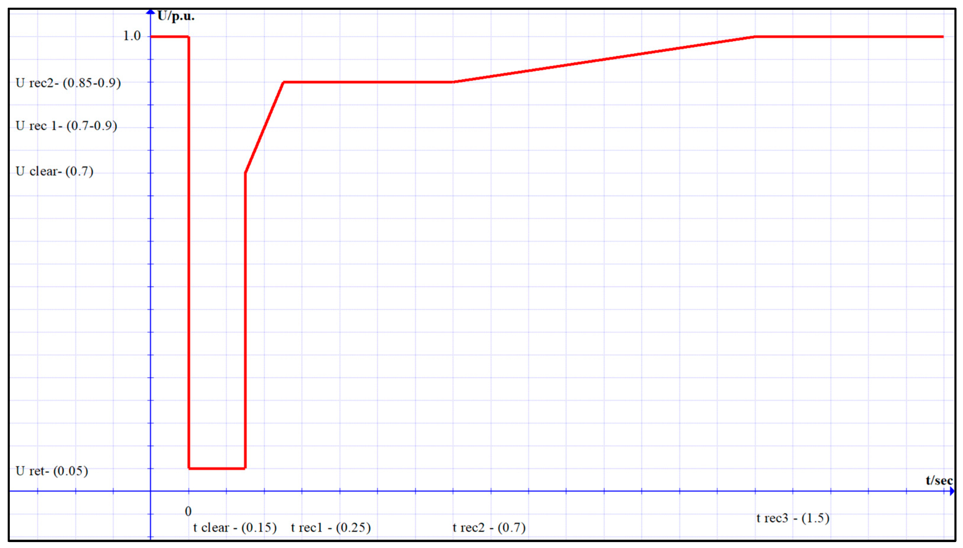
Opposite to islanding protection, it is expected that the DG provides fault-ride-through (FRT) capability [19]. FRT is the capability of DG to maintain the connection to the grid and operate through periods of low voltage at the connection point caused by faults, as presented by the curve in Figure 1. Nominally, voltage swells can fall to values of 0.05 pu with a duration ranging from 150 to 250 ms. Apart from voltage swells, faults cause significant deviations in frequency, resulting in the faulty disconnection of DG units for almost all methods, whether passive or active. The FRT requirement additionally affects the parameters of passive islanding detection algorithms, enlarging the non-detection zone (NDZ) and thus minimalizing their effectiveness. In conclusion, islanding protection methods must be immune to faults with a duration of at least 250 ms, providing FRT capability and reliable islanding detection.
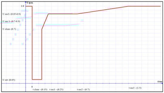
Figure 1.
FRT profile.
Commission Regulation (EU) 2016/631 establishing a network code on grid connection requirements for power-generating modules sets out harmonized connection rules for power-generating modules. Types A-D are power generators based on the maximum capacity of the power-generating module and its connection voltage level, which are defined by each country’s TSO. EU regulation 2016/631 sets out requirements that help maintain, protect, and restore system security in order to support the proper functioning of the internal electricity market both within synchronous areas and between synchronous areas. As per [8], DG facilities connected to the transmission or utility grid must, among other things, comply with the following requirements defined in network codes:
- General frequency requirements;
- General voltage requirements;
- Short-circuit requirements;
- Reactive power requirements;
- Protection requirements;
- Control requirements,;
- Power quality.
Parallel to the requirements mentioned above, Regulation 2016/631 sets mandatory requirements on information exchange (for types B, C, and D), stating that generation facilities shall be capable of exchanging information, whose protocols and variables may be defined by the relevant system operator if not explicitly stated in the Grid Code. The information exchange is carried out by specific communication protocols, of which the two most commonly used are IEC 61850 [20] and IEC 60870 [21], as defined in [22].
Reviewing the literature above, it is evident that the previously mentioned islanding detection methods have their own specific shortcomings. Passive detection methods are highly dependable within their threshold-set limits. They have a large NDZ if there is an employment of higher value-set parameters with the risk of prolonging the detection time but with more immunity to spurious tripping. On the other hand, lowering the value of protection set parameters reduces the NDZ but is followed by nuisance tripping for system events that were not the result of DG being in islanding mode. Active detection methods require additional control circuits to create adequate disturbances, increasing the implementation complexity. Nevertheless, an additional circuit may cause unpredicted effects on the electric power quality, such as the deterioration of the grid voltage quality and system instability [23]. Remote detection methods have high sensitivity and almost no NDZ; however, they require a proper communication infrastructure and additional secondary equipment. To summarize, choosing an effective anti-islanding protection method proves to be a big challenge. The selection is affected by various factors, such as the type of the DG unit, the topology and voltage level where it is connected, the proximity and number of other DGs, etc. The literature and praxis propose all of the mentioned detection methods without any of them being perfect. To be precise, the anti-islanding protection should only disconnect the DG in cases of islanding, not otherwise. The criteria to adequately determine or choose the correct anti-islanding detection method are not certain and should be investigated further as the grid, technology, and complexity of the grid increase. Smart grids are replacing traditional electrical systems, incorporating various smart meters and devices, and expanding communication and information exchange. Lastly, due to a mandatory information exchange between the system operator and DG facility, exploring its potential in new applications and functionalities is beneficial and worth investigating. Therefore, this is one of the main focuses presented in this study.
Reviewing the literature above, it is evident that the mentioned and described islanding detection methods have their shortcomings. The ever-increasing DG installation into the grid changes the system protection paradigm, replacing the existing models and methods of protection with new ones. To resolve the islanding protection issue, we present a novel voltage frequency differential algorithm described in this paper. The proposed algorithm utilizes the practical implementation of existing and future information and communication infrastructure using the distribution of measured sampled values from the grid to the point of common coupling at the DG by the IEC 61850-9-2 [24] protocol. The proposed algorithm implementation improves islanding detection compared to classical detection methods, lowering the NDZ and providing absolute immunity to false tripping in cases of non-islanding events and disturbances. Once the algorithm is implemented on a DG protection device, its detection method and set parameters are not affected and need not be changed in case there are new installation of DGs. Traditional detection methods can be negatively affected by the installations of new DGs, enlarging their NDZ, and possible failure in islanding detection. Algorithm plausibility was tested by simulations, comparing numerical analysis results of various system events in a network model to produce the algorithm’s response. To conclude the results, the algorithm was tested in a laboratory environment. Its implementation is on two state-of-the-art relays, with local communication and emulation of real-world grid disturbance records, mimicking both islanding and non-islanding events and disturbances.
After the literature review, identified research gaps, and the definition of the proposed algorithm, we propose the following contributions:
- A novel protection algorithm using voltage frequency differential harvesting mandates information exchange between DG and system operators through the delivery of remote frequency values to the DG relay, thus rendering nuisance tripping and more reliably detecting the DG’s islanding state.
- Demonstration of the successful algorithm operation against standard anti-islanding methods under different event scenarios by the use of dynamic simulation on a modified IEEE 14-bus system.
- Laboratory testing of the successful algorithm operation against standard anti-islanding methods emulating live disturbance recordings.
The rest of the paper is organized as follows: Section 2 gives the theoretical background of the relevant system dynamics and commonly used passive islanding algorithms; Section 3 explains the definition of non-detection zone and presents a sample of real measurement recordings during fault and islanding; Section 4 presents the working principle of the frequency differential algorithm; Section 5 analyzes the algorithm functionality in the modified IEEE 14-bus model for different islanding and short circuit scenarios; and Section 6 demonstrates the method and results of algorithm laboratory testing.
2. Theoretical Background
Analysis of the literature and working principles of ROCOF and VS detection methods, together with their pros and cons, spawned the idea of a new protection method. To better understand the principles of changes in electrical values during islanding, this chapter presents the dynamic correlations through the working principles of ROCOF and VS algorithms for synchronous generators. To better understand the idea, principles will be presented in mathematical form. To detect VS, standard relay algorithms use full voltage cycle measurements. Each measurement starts at the rising axis zero crossing and is repeatedly compared with the previous time cycle duration. The power difference sign defines the angle shift in such a manner that the current time interval exceeds or precedes the previous time interval.
The behavior of the DG is presented by the classical model generator swing equation, as shown with Equations (1) and (2):
Complete system inertia is represented as a constant H, synchronous angular velocity is ω0, mechanical torque power input is Pm, the electrical generator power output is Pe, and the power imbalance differential is ΔP. By solving the differential Equation (1) with the definition from the angular velocity Equation (2), the solution represents the rotor angle correlation Equation (3). The next step is the formulation of the angular difference or shift by Equation (4).
It is acknowledged that t − t1 is the cycle period in Equation (6); substituting it in Equation (5) follows:
The functional dependence of angle shift on time reference and power difference is given by Equation (7) [18]. The proposed correlations assume that in the case of an islanded generator’s speed, it increases or decreases depending on the power surplus or deficit.
Figure 2 presents an example of a VS protection model algorithm. The selected value of 3 degrees defines the frequency at which the relay should operate. Three degrees is equivalent to 0.414 Hz, where the fundamental period is 20 ms for a 50 Hz system [25].
In relays, ROCOF detection methods are similar to VS, detecting islanding in cases of active power differential between load and generation production [26]. Variations of frequency in the island part of the system are proportional to the active power difference [19].
ROCOF protection in relays can be set to calculate the rate of change of frequency for a different number of cycle periods. Some relays employ a fixed, non-settable number of cycles, while others offer a variable cycle number. Due to a different principle in ROCOF detection methods for a certain system event, relays from specific manufacturers can respond differently. Some relays use voltage zero crossing detection, while others use the discrete Fourier transform (DFT) method [27]. Similar to VS, ROCOF relays for non-islanding events have the tendency to false trip.
Equation (8) represents the mathematical expression for the rate of change of frequency, which is extrapolated from the classical model generator swing Equations (1) and (2):
In order to include the low-pass filter in the equation model, 1/(Tas + 1) is presented by the first order transfer function, where s is a derivative operator and Ta is the filter time constant. Implementing the first-order transfer function and solving Equation (8):
Equation (9) represents the functional dependency between the relay delay time and the rate of change of frequency for a given active power differential [28].
As mentioned earlier, for ROCOF calculation in most relays, voltage cycle zero crossing time, or DFT, is used. The calculation can be presented by Equation (10) [29]:
where fn is the current and moving frequency measurement, fn−4 is the measured frequency four cycles earlier, and T4 is the overall time of four recent cycles.
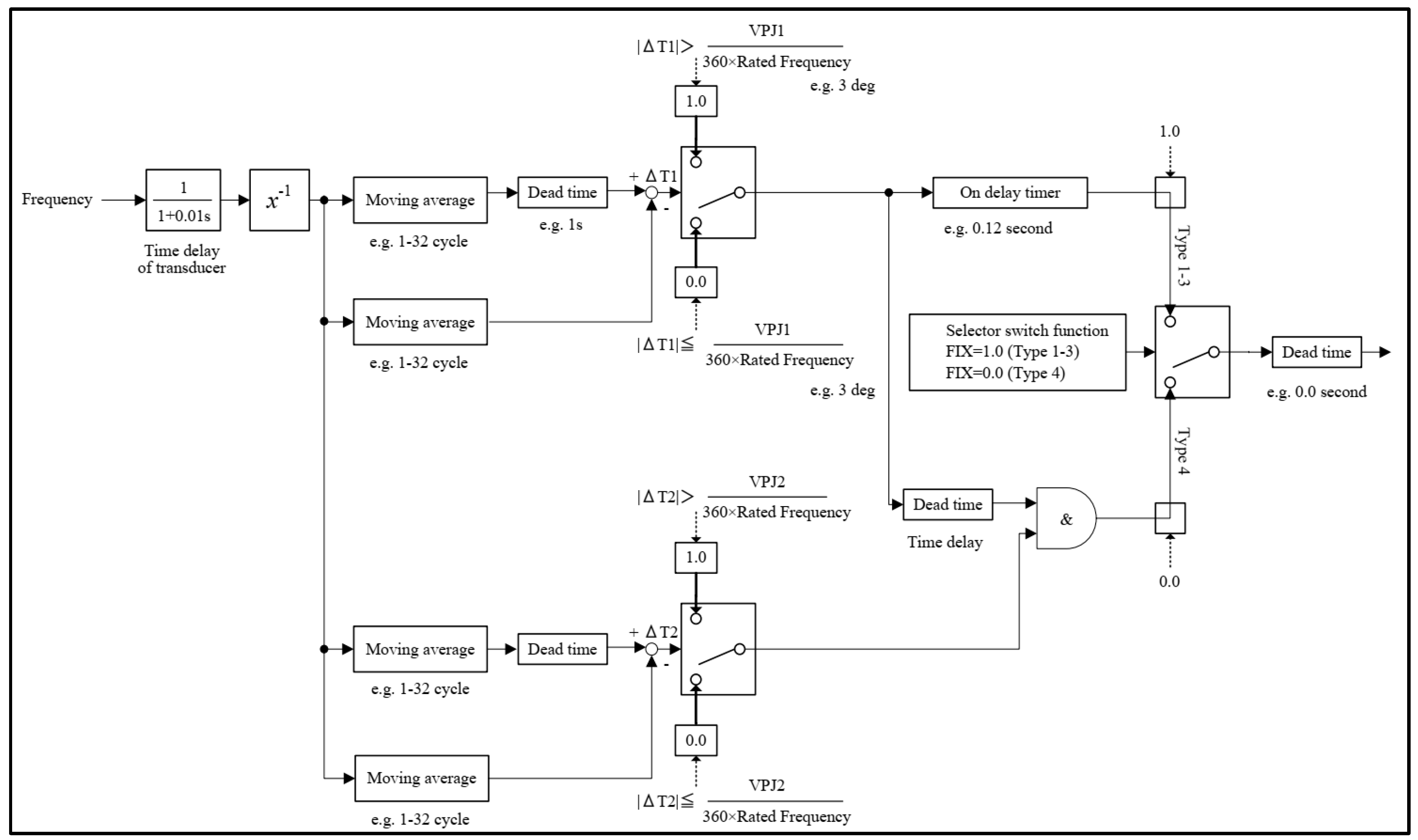
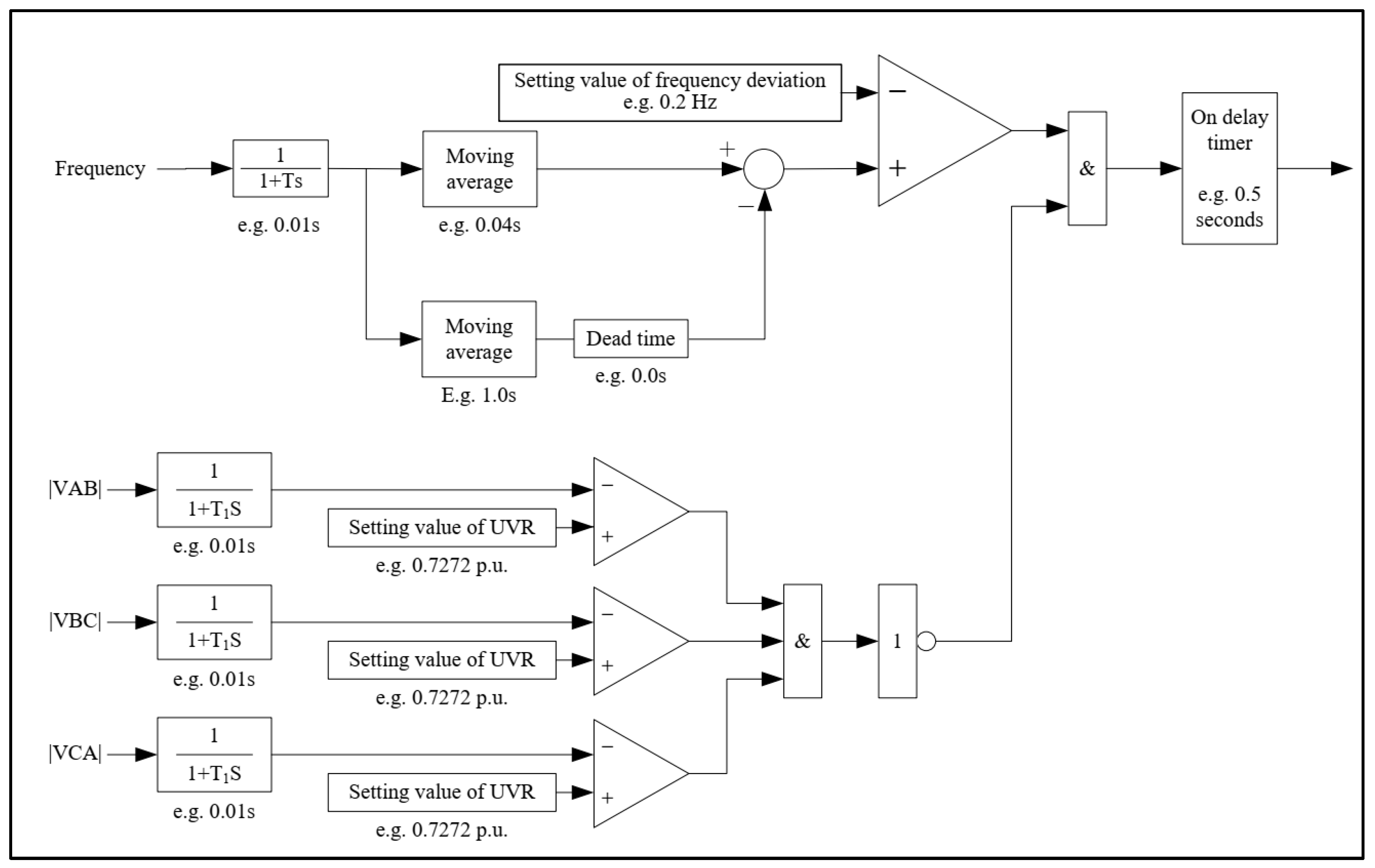
To better understand the principle of the working order for ROCOF relays and as an introduction to the idea of the proposed FDA, Figure 3 presents an example of a ROCOF protection model algorithm.
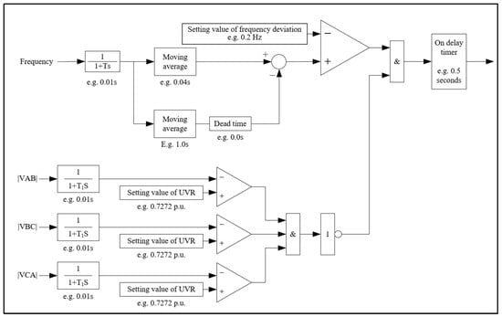
Figure 3.
Example of the ROCOF algorithm [30].
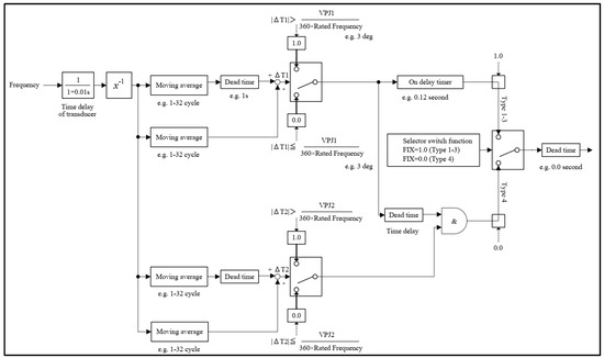
Figure 2.
Example of the VS algorithm [30].
Figure 2.
Example of the VS algorithm [30].
3. Non-Detection Zone and System Events
This chapter presents the definition of NDZ and shows disturbances recorded by devices installed in a real-world distribution network. Successful islanding detection is determined by its set parameters in correlation to the active power difference of the remaining load and the active power output of the DG. A major issue with the VS and ROCOF protection is false tripping for faults on the adjacent feeders or by other disturbances in the system. NDZ of DG protection can be defined as the grid conditions range without detecting the islanding state. To define the dependency of VS and ROCOF parameters on the active power differential, NDZ can be presented as the percentage probability value for the time interval duration of islanding non-detection. The most constructive way is to visualize the cross-section of active load on the DG active power curve at the grid point that is observed (for simplification, the DG power output is constant). The VS or ROCOF protection setting can define the NDZ by directly giving the minimum active power differential of the load, contrary to the DG active power output needed for islanding detection.
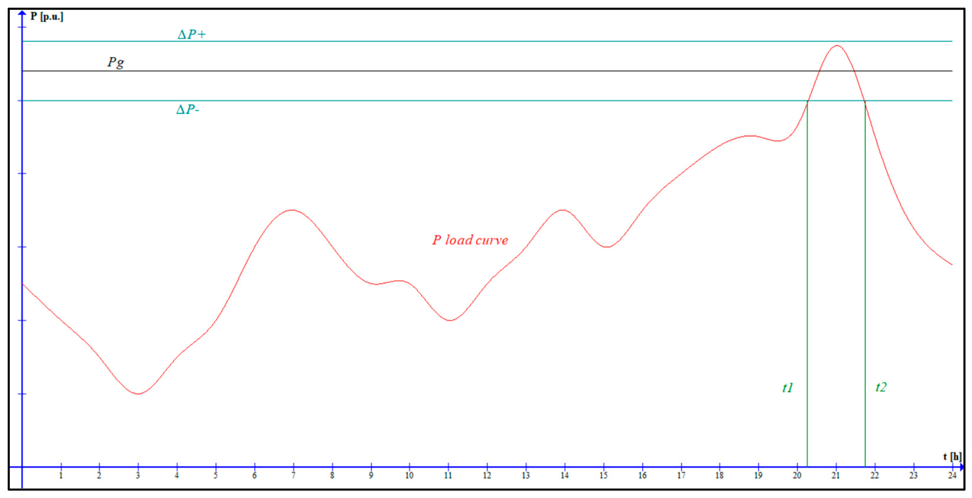
Using Equation (11), NDZ probability can be calculated as the quotient of the time interval of the ∆P+ and ∆P− markers crossing the load curve with the condition that the load curve needs to be between the markers. DG islanding protection NDZ is marked by green lines and defined as the positive ∆P+ or negative ∆P− active power differential, meaning ±10%, presented in Figure 4, for standard settings of VS-4 and ROCOF-1 Hz/s on a 1 MW base.
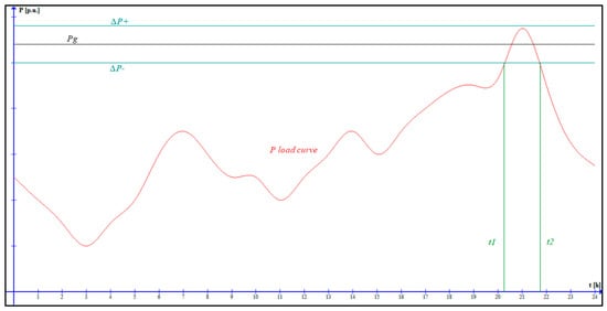
Figure 4.
Integrated load and generator active power curve.
The load curve crosses the ∆P+ and ∆P− markers between 20:15 and 21:45 h by employing Equation (11). The calculated probability of the NDZ is 6.25%. As a conclusion for certain points in the grid, NDZ probability can also be calculated if a certain circuit breaker or circuit breakers have their load curve crossing the ∆P+ and ∆P− markers [31].
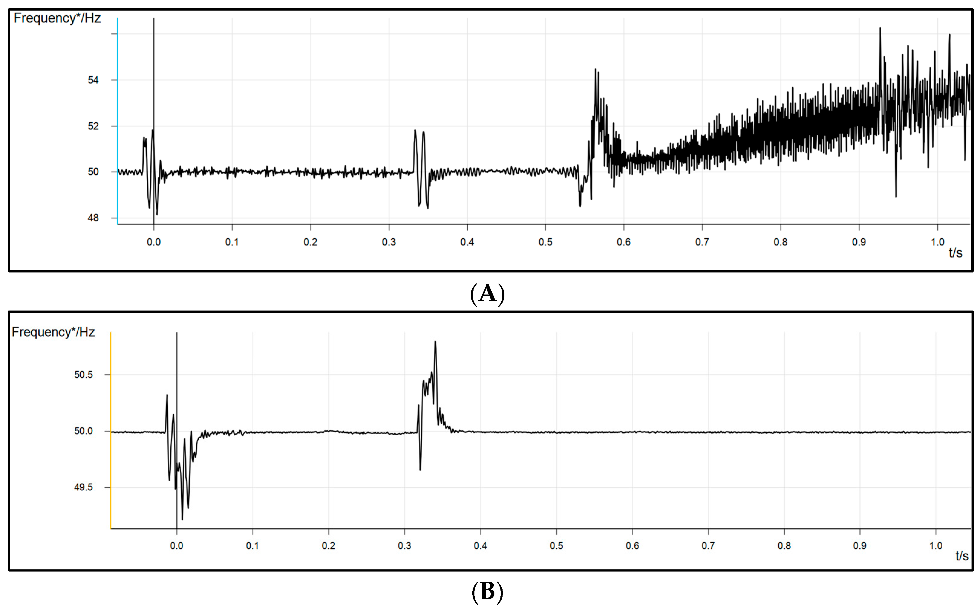
As an example, Figure 5A presents a real-time disturbance recording of frequency measurements during a fault on a transmission station busbar that is relatively far from the DG point of common coupling (PCC) and is similar to the BUS-05 configuration according to the grid model in Figure 6. Figure 5B shows the disturbance recording of frequency on the DG feeder in PCC (Point of Common Coupling). ROCOF protection for DG did not trip due to the high setting value. Later, in the second stage of over-frequency protection, the grid relay disconnected the DG on the PCC. DG from the disturbance recording (B) is modeled as GEN08 on the IEEE 14-bus model.
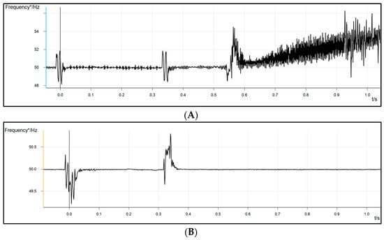
Figure 5.
Live disturbance records showing frequency. (A) Frequency on the DG bus bar; (B) frequency on the remote bus bar in the grid.
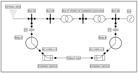
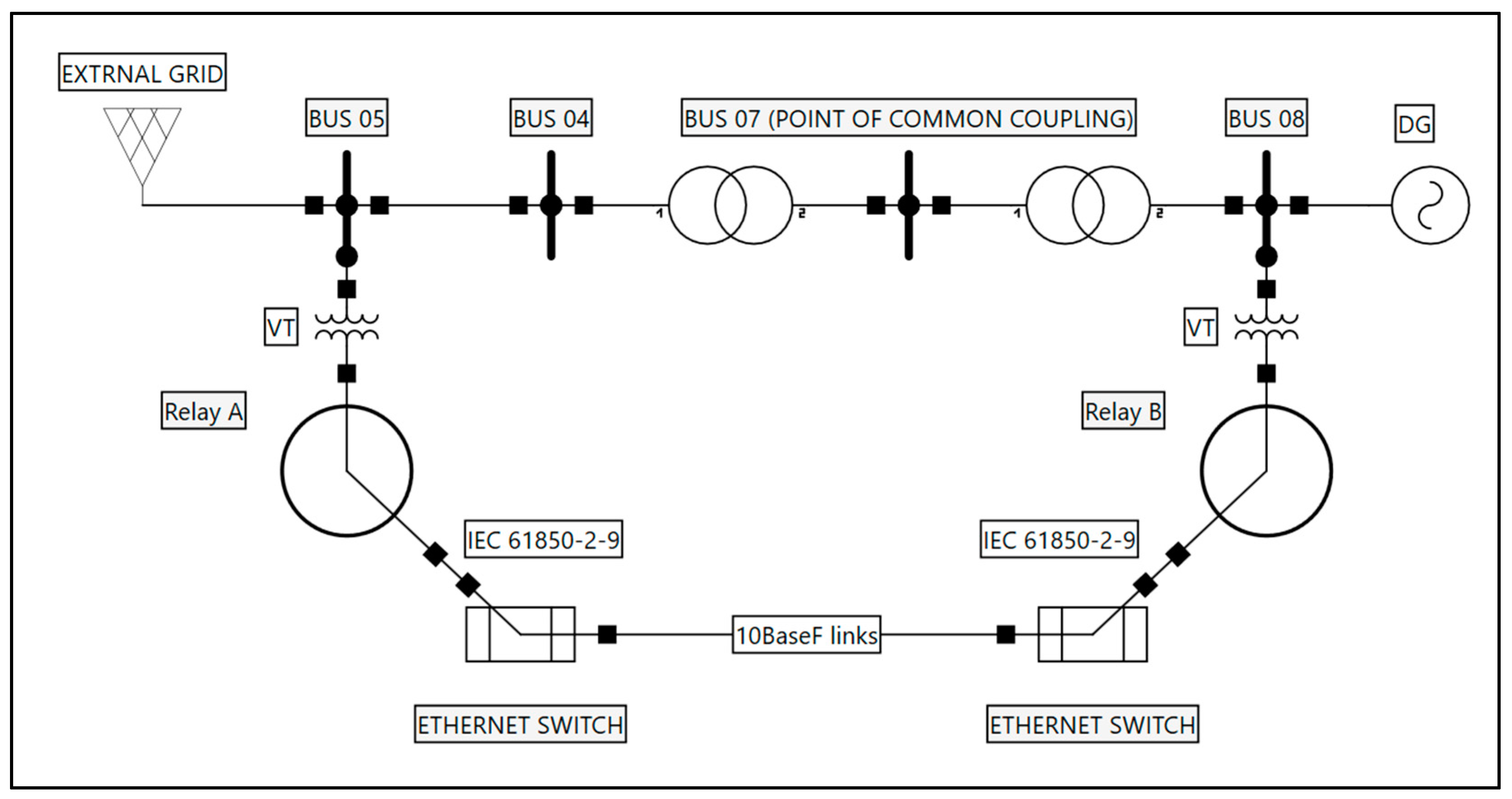
Figure 6.
Communication scheme.
4. Frequency Differential Algorithm
The intensive process of developing renewable energy-powered generators in both the transmission and distribution grids started a decade ago. Anti-islanding protection is still mandatory, making it harder to remain efficient in its task with the system’s complexity. Experience in anti-islanding protection utilization has taught us that the margin of settings for ROCOF and VS is very thin between successful and spurious operations for which a trip is unnecessary. Recent and yet-to-be-connected DG facilities are obligated to provide a wider range of automated dynamic responses with greater resilience to operational events and a higher level of system operator control and information [19]. Besides standard information on operating conditions, the establishment of communication between the system operator and DG gives the opportunity to utilize the process-bus measurement values. The principal communication scheme is presented in Figure 6.
Substation and grid digitalization are achieved by using IEC 61850-9-2 sampled values through process-level communication. The IEC 61850-9-2 standard defines the Specific Communication Service Mapping (SCSM) for the transmission of sampled values. The standard applies to all devices related to process measurements of the logical node group having a digital sampled value output stream, such as current and voltage, merging units, or devices acting as group publishers, as well as subscribing intelligent electronic devices. The proposed algorithm utilizes the benefits of “live” streaming of sampled values in the form of a protection algorithm. In theory, the proposed algorithm can work on a wide range of proprietary and dedicated protocols, like the line differential protection protocol. However, it is better to use the IEC 61850-9-2 standard together with the other benefits that it provides. The main goal is the delivery of grid frequency measurements to DGs using the IEC 61850-9-2 protocol, in this case, from a transmission–distribution point of common coupling and implementing the measurements in a new algorithm. Compensation for the actual communication delay is called synchronization latency, which needs to be set only on the subscriber side. This is required to compensate for a possible delay during the distribution of the measurement signal. The signal is delayed by cables, star couplers, etc., which are all part of the distribution chain. The delay caused by the cables can be calculated, and its typical value is 5 ns/m. The absolute threshold value for the algorithm blocking due to time out of the time value stream is 4 ms. Relay A serves the function of a publisher of sampled measured values for this proof of concept. Only frequency measurements are distributed to subscribers, in this case, Relay B. The proposed algorithm structure is programmed in the Siemens DIGSI 5 CFC editor. CFC is used to create the entire software structure of the CPU, placing blocks on function charts, assigning parameters to them, and interconnecting them. Frequency measurements are validated at the source level, with both the publisher and subscriber validating the viability of their measurements through condition flags. For the publisher to transmit the frequency values to the subscriber, we set a condition for the existence of line voltage measurements with a value greater than 0.1 p.u., and this sets the flag status to 1. The measured value in CFC is time-stamped. It is important to note that the relays connected on the process bus are also time-synchronized, and the sample rate can be adjusted from 80–256 samples/period on a 50 Hz system, while our proposed algorithm uses 80 samples/period without losing the accuracy and functionality.
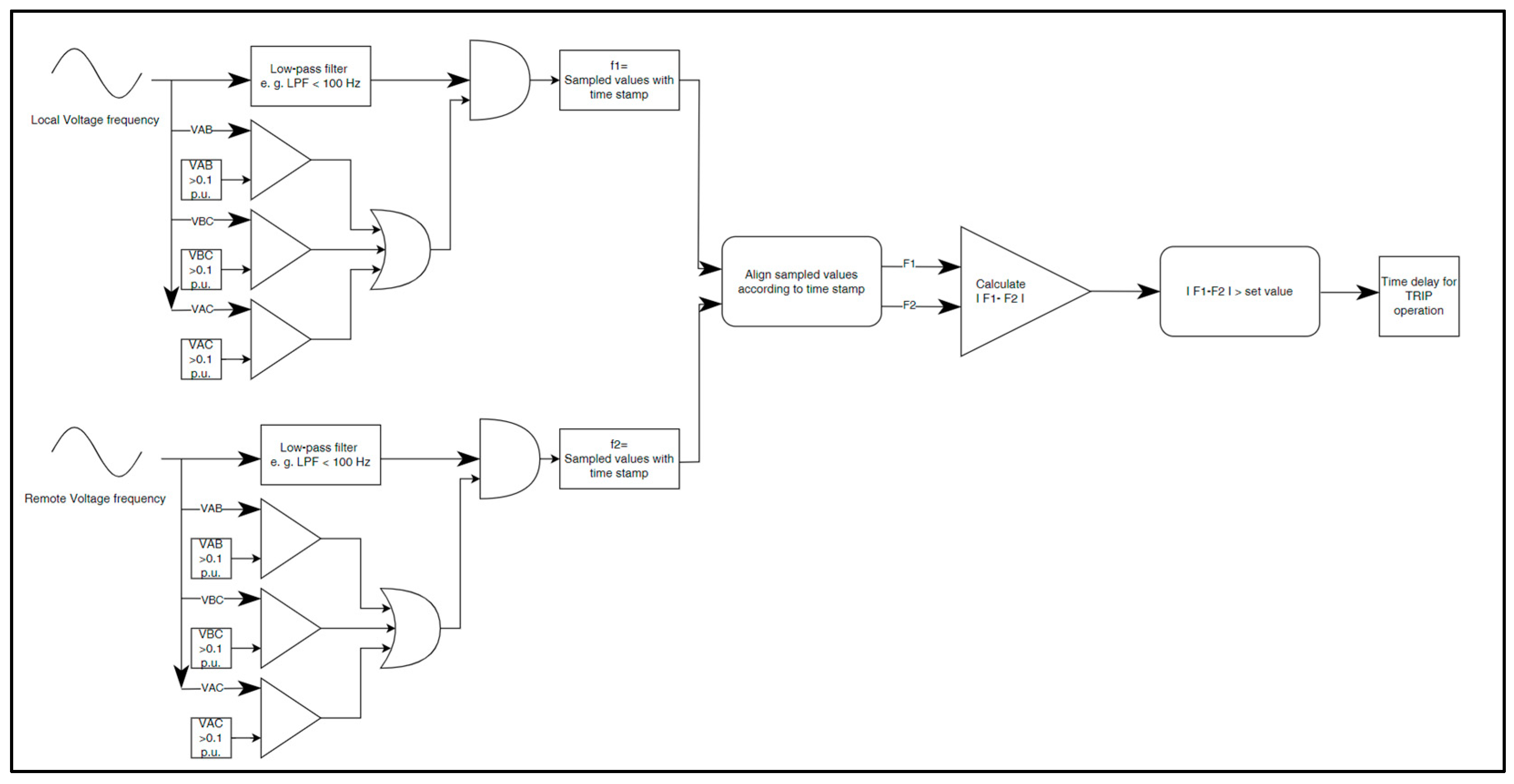
The function of the differential frequency algorithm (FDA) is shown in Figure 7.
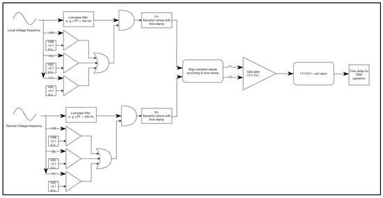
Figure 7.
Frequency differential algorithm.
A subscriber, in our case, Relay B, acquires process-bus frequency values from the publisher and directly relays them in the CFC chart. The first function block in Relay B validates its own frequency measurements using the same condition as the publisher—line voltage measurements are present and are greater than 0.1 p.u. The next function block aligns the values f1-subscriber and f2-publisher according to timestamp values. The function block outputs are two variables, F1 and F2, that are inputs for the next function block. The values of F1 and F2 are differentiated, and the absolute differential value is compared to the set value. The differential function block repeatedly compares the differential value to the set value, giving the flag 1. With the flag value 1, the next function block repeatedly checks the flag for the whole period of the set time delay for the trip operation. If the flag changes to 0, the function block resets to start from 0, waiting for the flag value of 1. When the output of the function block results in flag value 1, for the whole period of the time delay, the function block is fully activated for the relay to trip and disconnect the DG from the grid. The condition for the existence of line voltage values larger than 0.1 p.u. in the algorithm block is essential for a plausible detection of islanding.
For further analysis, the algorithm parameters will be:
- Set value of frequency differential: Fdiff = 0.2 Hz;
- Set value of time delay: tdelay = 0.1 s.
5. Numerical Model Analysis with Algorithm Response
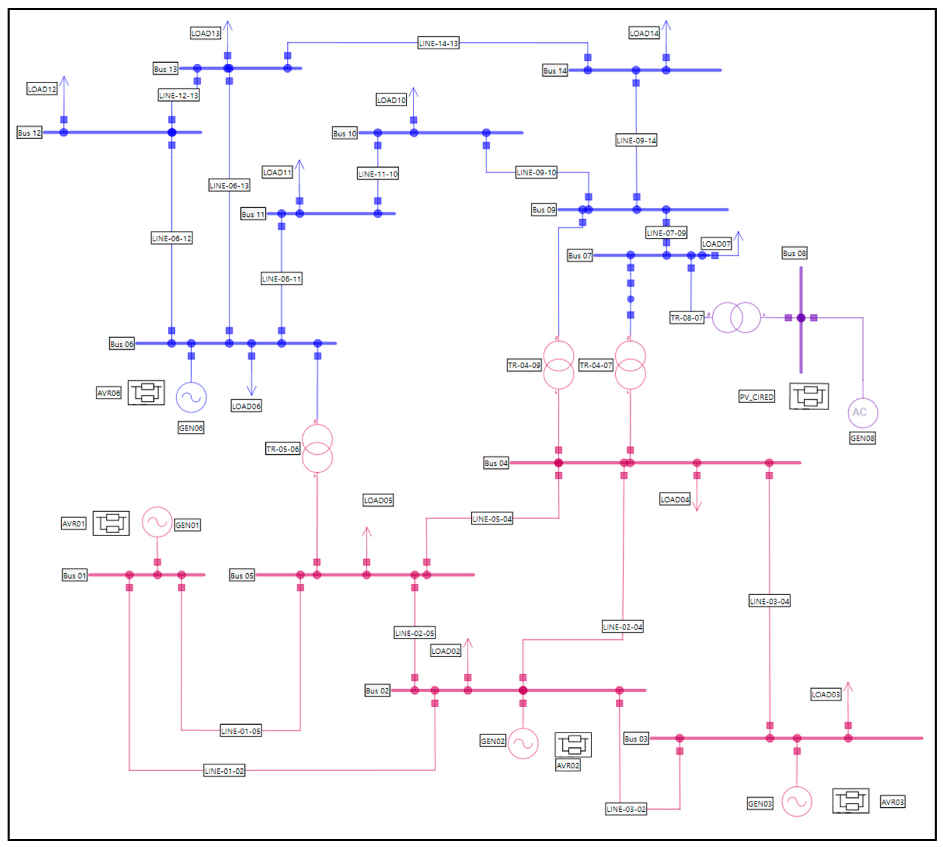
For further study of system events similar to those shown by disturbance recordings in Section 3, RMS numerical analysis is conducted in the NEPLAN V10.9.4.1 software on a modified IEEE 14-bus network [32]. The NEPLAN dynamic analysis module can perform electromechanical (RMS) and electromagnetic transient studies (EMT) to analyze the dynamic behavior of the power system under various operating conditions and system disturbances. The dynamic module has a fast and robust solver that is able to solve large-scale networks with high performance in terms of numerical stability, accuracy, and resolution time. The bus model is illustrated in Figure 8. The IEEE 14-bus system is a good approximation of an electrical power system with elements of power generation, transmission, distribution, and distributed generation [31]. Modifications to the original parameters of the model include a 50 Hz system frequency, and the GEN08 is a photovoltaic generation unit with a rated power of 10 MVA, while the exciter for the GEN08 is modeled according to [30]. Numerical simulation of system events will provide indicative results on the behavior of frequency on selected nodes following short circuits and islanding events.
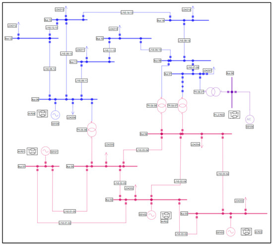
Figure 8.
The 50 Hz IEEE 14-bus model.
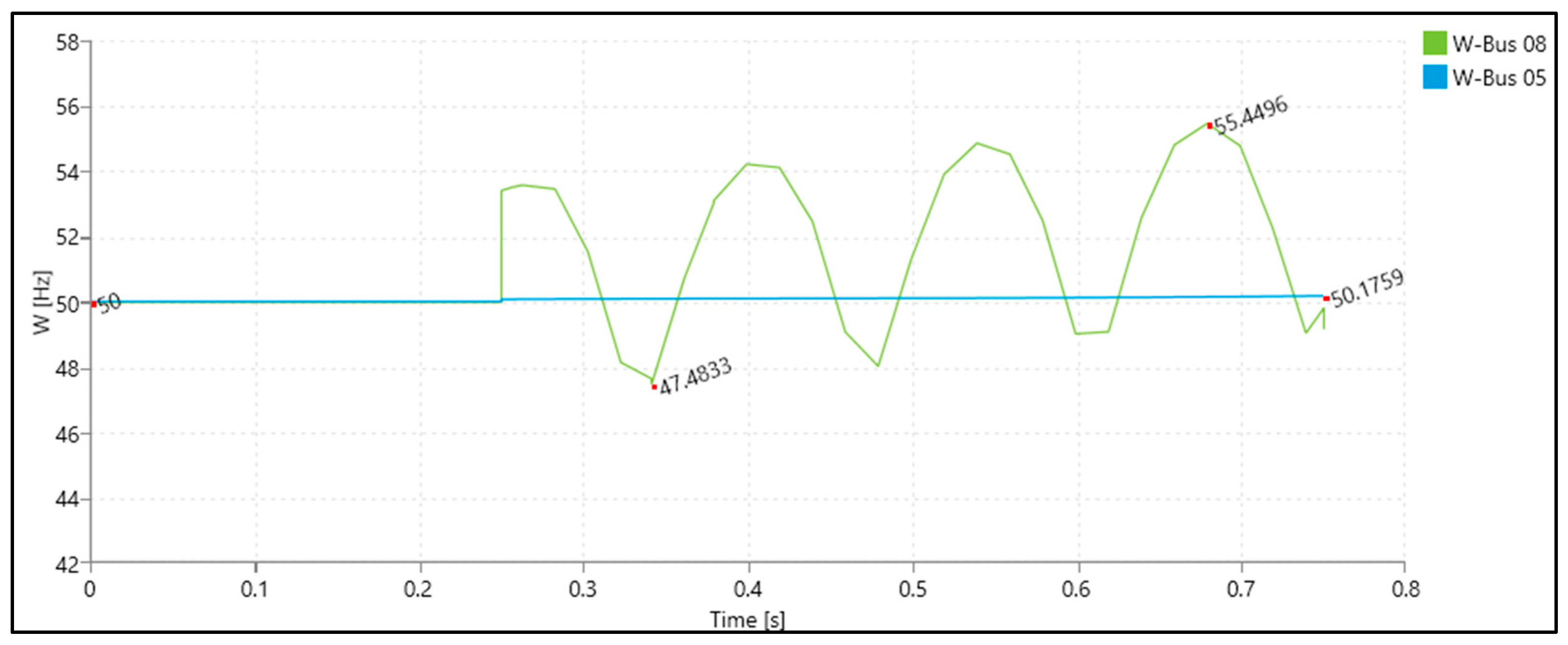
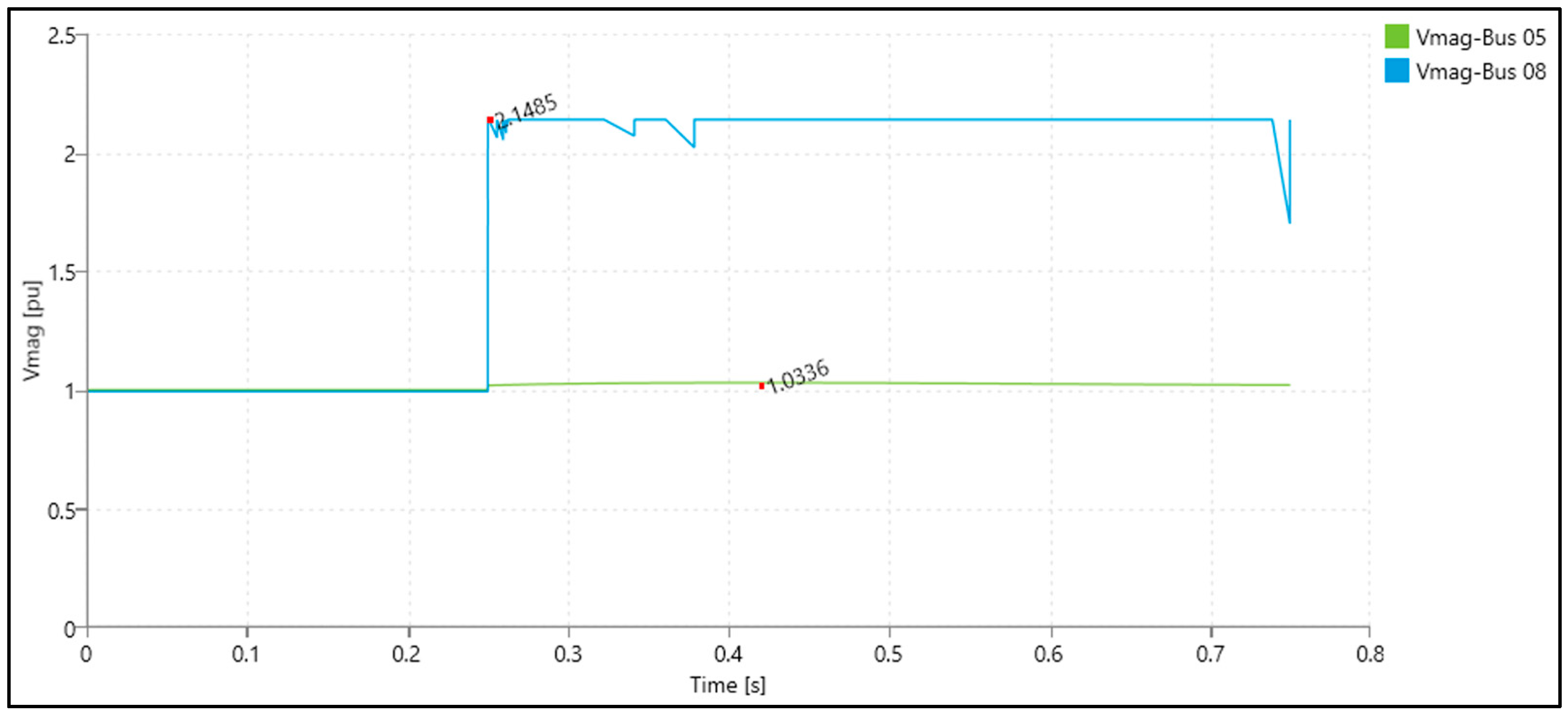
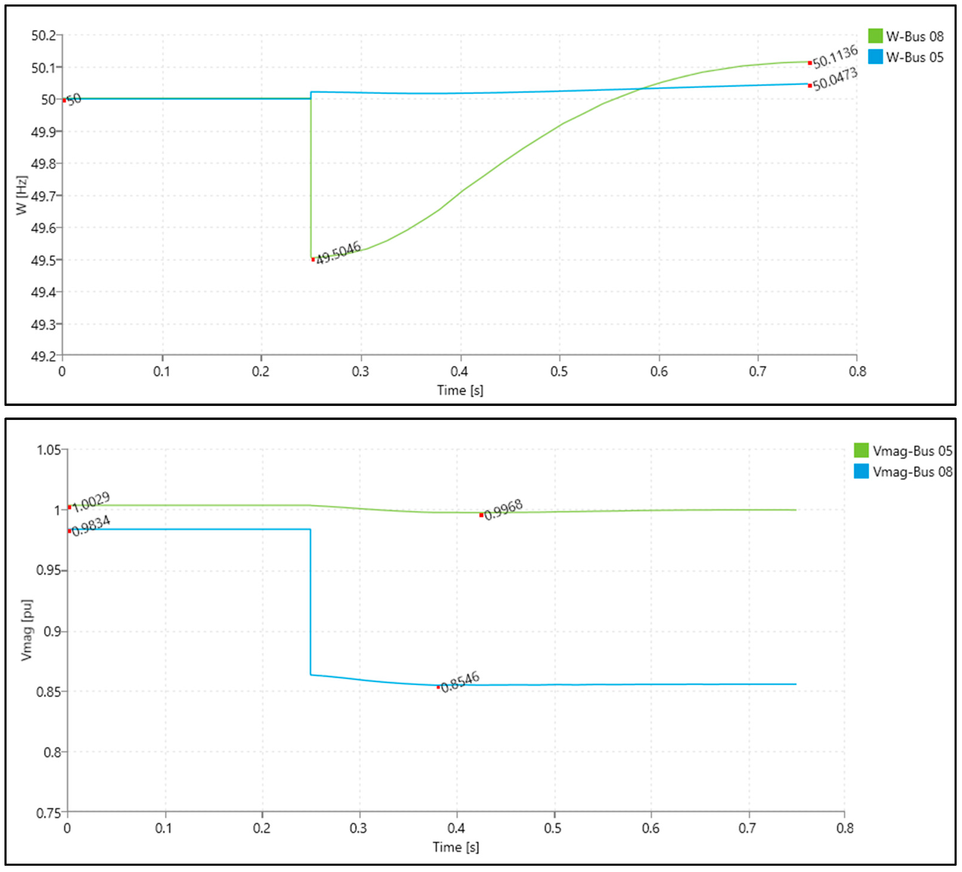
Numerical analysis considers two sets of grid events. The first set considers short circuit analysis, and the second analyzes the different case scenarios for islanding without the occurence of short circuits. To correlate with Figure 6 and Figure 8, Bus-05 will represent the base reference bus from which Relay A requires the voltage and frequency measurements, and Bus-08 will represent Relay B, requiring the same measurements. Bus-05 and Bus-08 are not at the same voltage level, which is why the proposed algorithm uses p.u. validation values. It is important to mention that for the purposes of dynamic presentations in Figure 9 and Figure 10, all other (undervoltage, underfrequency, etc.) protections on the model are inhibited. For analysis, in Figure 11, active power differential of load and production is set at +5%, while in Figure 12, the active power differential of load and production is set at −15%. For short circuit analysis, in Figure 9 and Figure 10, a sudden change in frequency is the result of the circuit breaker’s opening and clearing the fault, as confirmed by the example disturbance record in Figure 5.
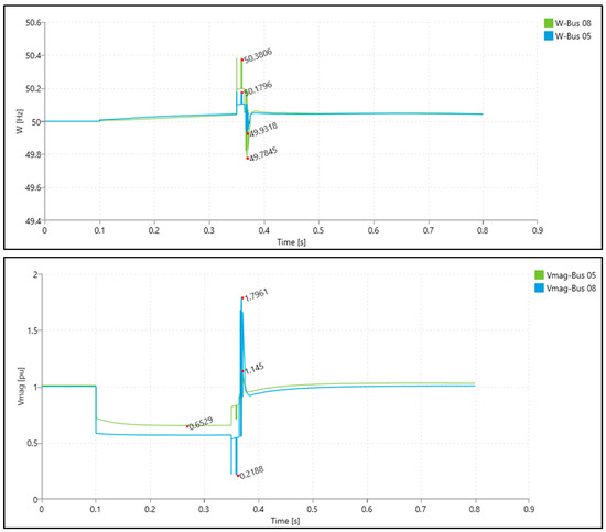
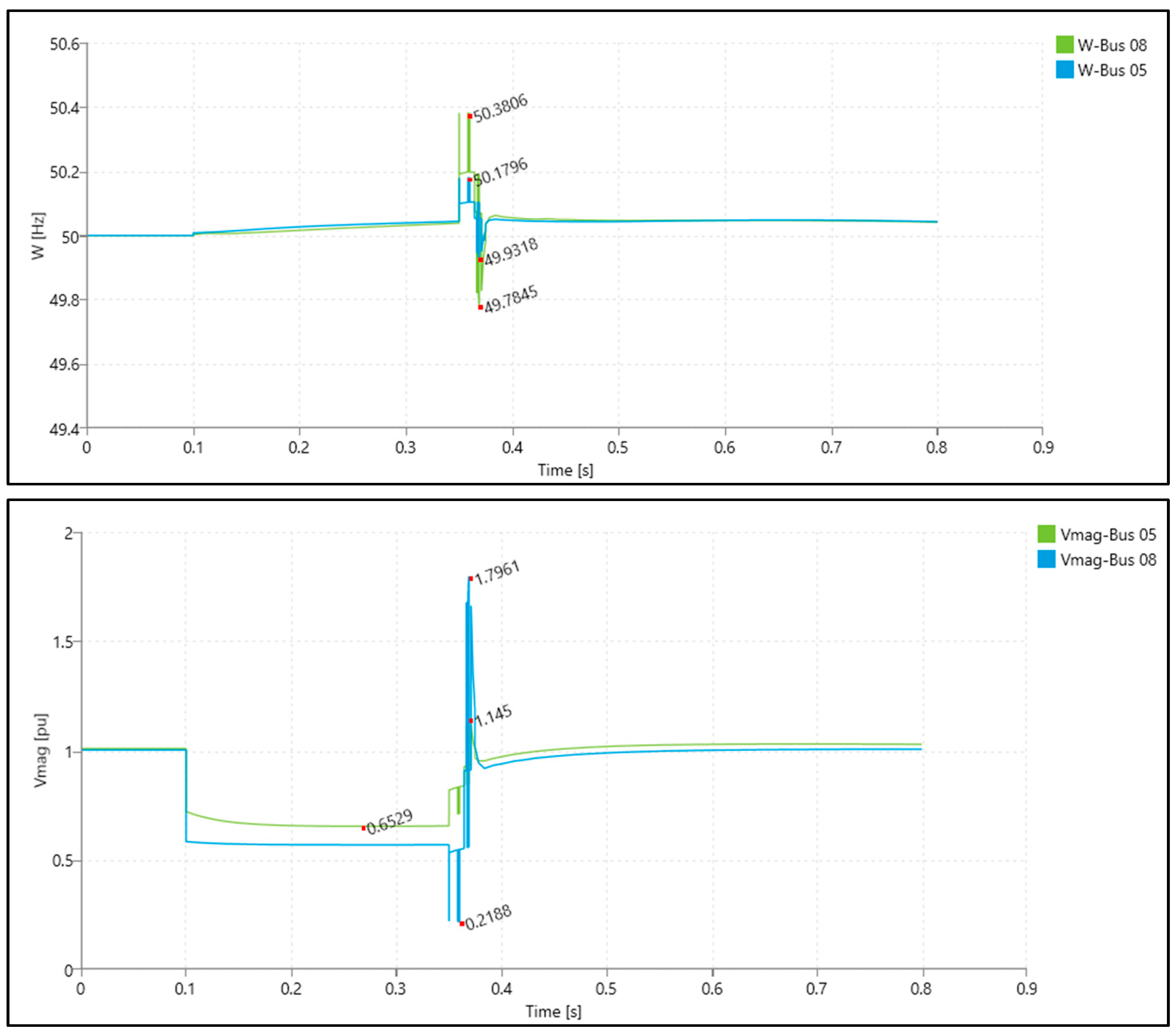
Figure 9.
Frequency and voltage magnitudes for a short circuit on Bus-14.
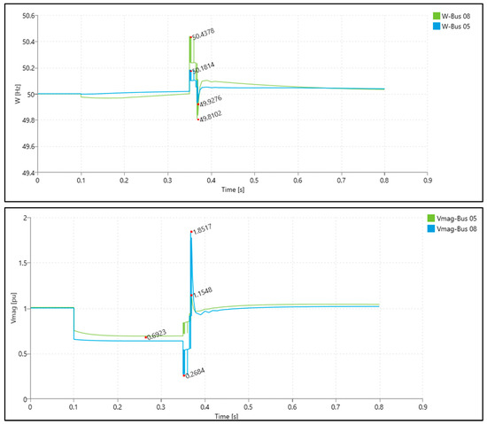
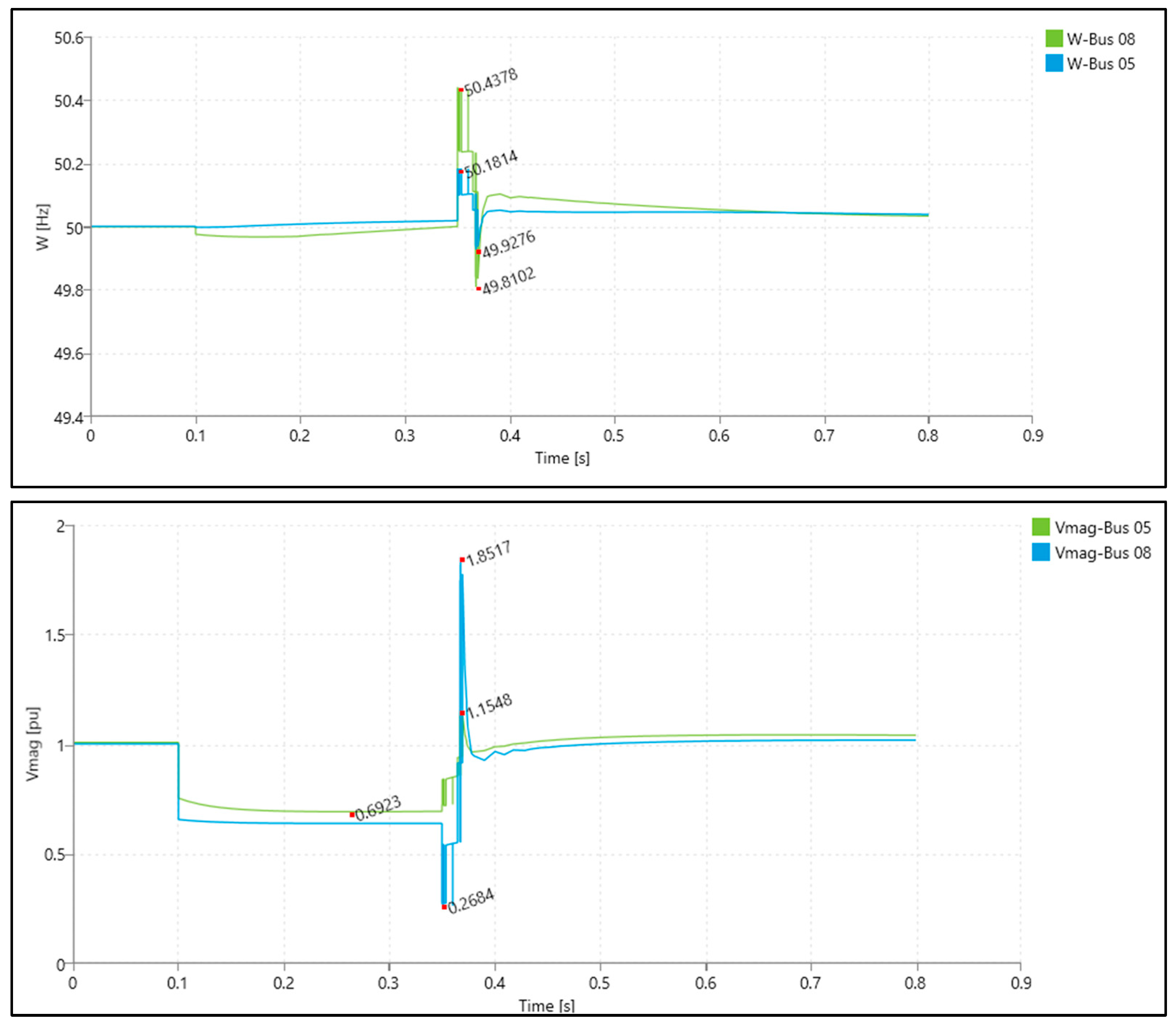
Figure 10.
Frequency and voltage magnitudes for a short circuit on Bus-10.
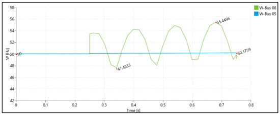
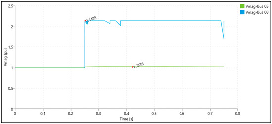
Figure 11.
Frequency and voltage for an islanding event on Bus05-08 with Gen-08.
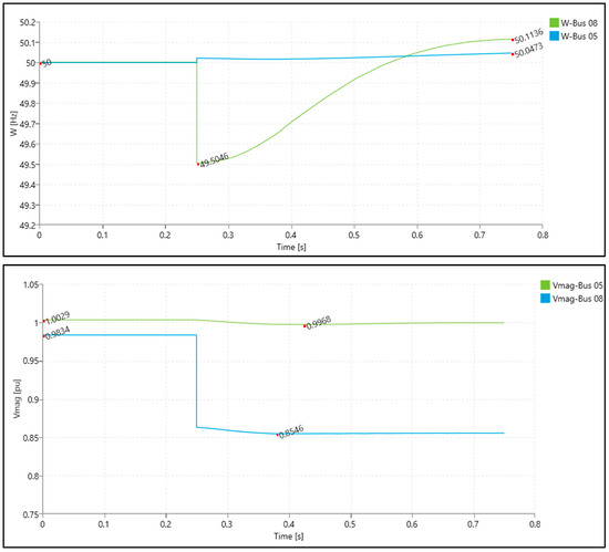
Figure 12.
Frequency and voltage for an islanding event on Bus07/10 and 14 with Gen-08.
Figure 9 represents the dynamic time simulation plot results of frequency and voltage on reference Bus-05 and Bus-08 with the three-phase short circuit on Bus-14, while Figure 10 represents the same when the three-phase short circuit happens on Bus-10. Frequency and voltage dynamic analysis for events shown in Figure 9 and Figure 10 indicates that the frequency differential value does indeed initially exceed the set value. As described in Section 4, algorithm variables F1 and F2, where F1 is the local and F2 is the remote frequency, are aligned by their exact time stamp before they are differentiated. This alignment provides the algorithm with immunity to errors, even in the case of large disturbances such as transients. If the differential is high enough to start the trip function counter, it will reset when the usual steady-state values are achieved and the disturbance is cleared, ensuring there is no islanding on the DG, in which case the relay will and must trip. The algorithm frequency differential flag changes from 1 to 0 before the algorithm set time elapses due to the stabilization of the system and DG frequency when the fault is cleared. This confirms that the algorithm is immune to spurious tripping by faults that do not result in islanding, contrary to the ROCOF protection that would trip. The algorithm input frequency measurement validation condition on the voltage measurement is also satisfied.
Figure 11 represents the dynamic time simulation plot results of frequency and voltage on reference Bus-05 and Bus-08 with the islanding event of Bus-07 (with their respective loads) coupled to Gen-08. Figure 12 represents the same but with the islanding events of the Bus-07, Bus-10, and Bus-14 (with their respective loads) coupled to Gen-08. For events shown in Figure 11 and Figure 12, the analysis shows that the change in frequency does occur on the island part of the grid, especially on the DG bus, but is consistent on the grid. Analysis has also shown that the fluctuation of frequency on the DG bus can go from a negative to a positive differential, opposing grid frequency and active power imbalance, which is why the algorithm takes an absolute value.
Frequency plot results for Bus-05 and Bus-08 were uploaded into an algorithm simulator. The first step in the simulator was getting the result of the frequency differential from the plotted values. It is needed because the algorithm cannot be modeled in NEPLAN. When this was done, the next step in the simulator was to determine the FDA response behavior based on the resulting plotted data. Simulation results give the differential frequency value algorithm start and trip flags. The FDA test results for the analyzed dynamic simulations of every event are shown in Table 1. The results show the proposed algorithm success matrix with the calculated frequency differential value for every event together with the algorithm, resulting in a start-to-trip or just a start flag.

Table 1.
Algorithm success matrix.
6. Laboratory Algorithm Testing
The other, or to say the best, way to test the working principles of a protection algorithm is by reproducing the results in a laboratory environment. This chapter will describe the actual procedure of FDA implementation, the types of relays used together with their proprietary configuration tools, the required communication protocol for measured values, and the emulation equipment. Input measurements will be emulated (uploaded) from real live disturbance recordings from the relays installed in actual substations. Test results will show how the algorithm would respond in real-event scenarios (during faults and islanding).
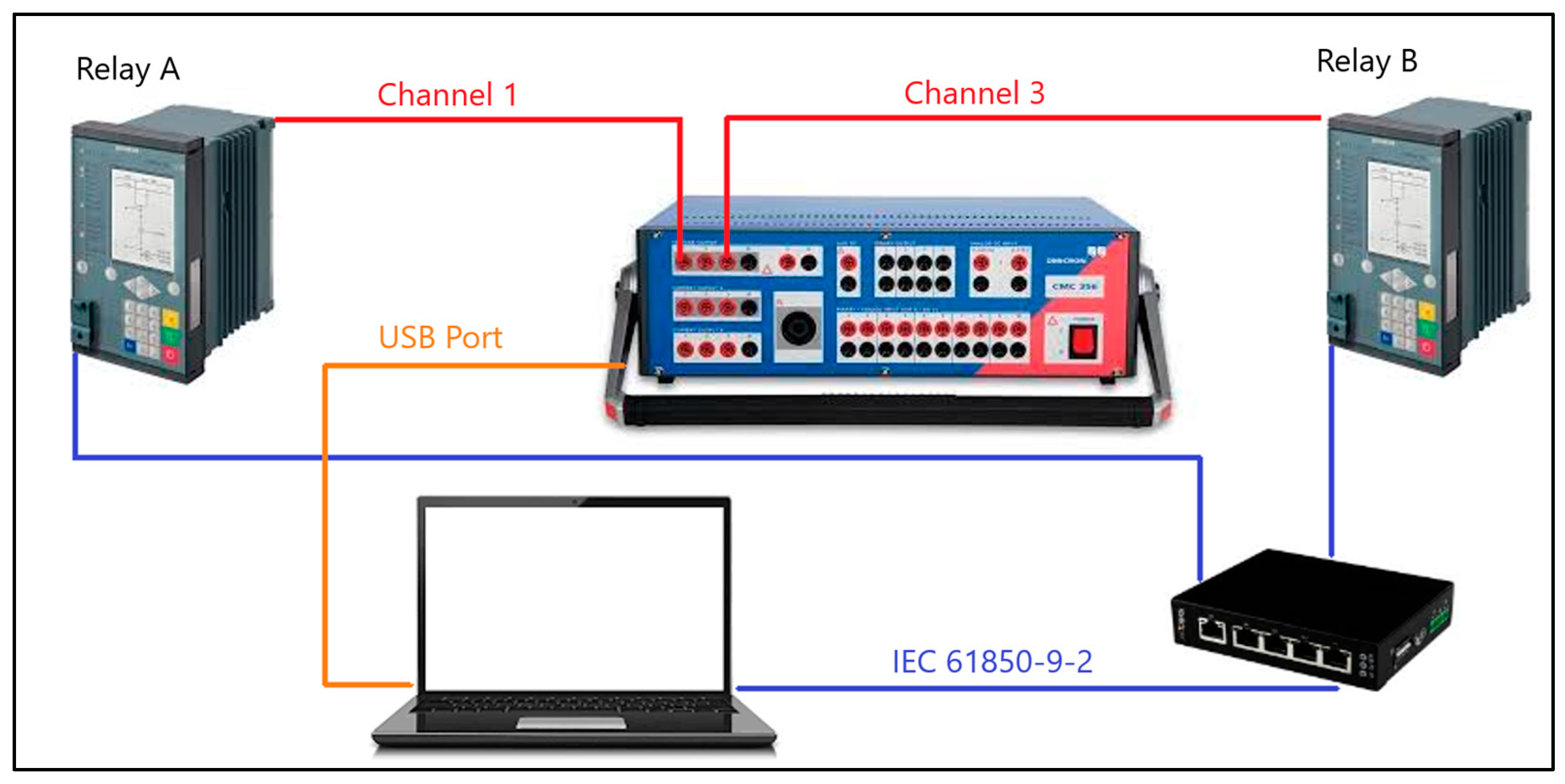
As mentioned in Section 4, the voltage frequency differential algorithm concept is implemented in two state-of-the-art Siemens 7SJ82 numerical relays. The Siemens DIGSI5 CFC editor is used for algorithm development and programming in Relay B. Relay A only acts as a publisher, generating voltage measurements and delivering them to Relay B via the process bus via the IEC 61850-9-2 protocol through a LAN switch. The equipment connection is shown in Figure 13. The test simulation presents a collection of real-time disturbance records of various system faults and islanding situations in different scenarios. The emulation process of grid voltage values is conducted by the relay test kit Omicron-CMC353. Channel 1 is connected to the voltage input of Relay A, and Channel 3 is connected to the voltage input of Relay B. Emulation data are generated from the uploaded disturbance records by a single selection of copying/emulating only voltages. The results in this section are conducted by emulating the disturbance recording described in Section 3. Overall, the FDA testing was conducted on numerous disturbance recordings, and all were proven successful. The time alignment of disturbance records is determined by their time stamp, so the grid event is correctly time-dependent on both channels. PC manages the time synchronization through the IEC 61850-9-2 protocol.
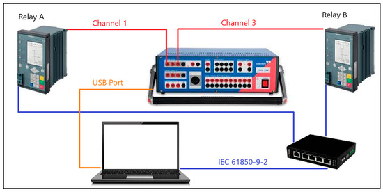
Figure 13.
Laboratory test set.
Testing is conducted in two different settings. The first test has a voltage frequency differential algorithm with a setting of 0.1 Hz and a time delay of 0.25 s, and the second has a setting of 0.4 Hz and a time delay of 0.1 s. In the additional Relay B test, two protection stages of ROCOF 1 and ROCOF 2 are activated. The first stage is set at 2 Hz/s with instantaneous tripping, while the second stage is set at 0.5 Hz/s with a time delay of 0.1 s. The addition of ROCOF stages will represent the means of immunity testing for the proposed algorithm on spurious tripping, contrary to the conventional protection method.
The disturbance recording from Figure 5 is divided into three sections: Section-1 (0.1–0.25 s) analyzes the algorithm behavior for a first short circuit occurrence, and Section-2 (0.25–0.5 s) analyzes the algorithm behavior on fault isolation. While Section-3 (0.5–1 s) analyzes the islanding state, the proposed algorithm for spurious tripping is contrary to the conventional protection method.
Table 2 gives a comprehensive verification of the FDA in conjunction with two ROCOF setting stages. For every section of the emulated disturbance recording, results are indicated through the trip flag issue together with the tripping time values. It is clear that the FDA, although set low, follows the restriction given by the remote voltage-frequency measurements in cases of short circuit occurrences, while the ROCOF stages are locally restricted and thus cause a spurious trip issue.
Table 2.
Algorithm test results.
The results of field testing after incorporating the algorithm into the existing relays and communication infrastructure imply that the existing communication infrastructure can incorporate the IEC 61850-9-2 standard, and the relays are also compliant. The recent “swarming” of DG into the grid was and still is followed by mandatory information exchange and can employ the mentioned communication protocol. The proposed algorithm joust needs to be uploaded onto an existing protection relay on PCC and configured as a subscriber to receive sampled measured values. On the other hand, the publisher of sampled values needs to be relayed through the existing communication infrastructure in the grid to the relay at PCC. After the algorithm and measurement implementation, field testing should consist of two levels. The first level includes the verification of the successful transmission and reception of measured values through the communication network. This is provided with no communication time-out signal and the provision of a frequency differential value at the PCC relay. The next level is the simulation of frequency deviations by secondary injection of a voltage signal to the relay at PCC. The injected signal should be in two stages of testing: the first stage will simulate over-frequency exceeding the set differential threshold while holding the publisher frequency measurement from the system and confirming the trip signal. The second stage will simulate the under-frequency frequency, also confirming the trip signal.
7. Conclusions
This paper presents a novel protection algorithm based on a voltage frequency differential that disconnects the DG or part of the grid in the event of islanding. This algorithm is based on communication structure by means of process-bus sampled values via the IEC 61850-9-2 protocol. The plausibility of this algorithm is first tested through dynamic and algorithmic simulations that show indications that the algorithm is successful. The next logical step was algorithm implementation in the relay systems and laboratory testing. Testing gave the actual working results of the algorithm regarding the time synchronization of live measurements and trip time command issues. The analysis results indicated that the algorithm is more resilient to spurious tripping than the conventional protection schemes, thus adding to the reliability of the system as a whole. This algorithm can employ low-frequency differential values, drastically reducing the NDZ in all DG types, regardless of its size and voltage level at the point of common coupling. Furthermore, it supports the ability of the DG to fault-ride through demand. In future studies, it is expected to implement the algorithm in field testing using IEC 61850 on existing relay and communication architectures and to adapt this algorithm so it can be implemented using the IEC 60870.
Author Contributions
Conceptualization, Z.M. and J.H.; Data curation, Z.M.; Formal analysis, Z.M.; Investigation, Z.M. and J.H.; Methodology, Z.M. and J.H.; Project administration, J.H. and T.C.; Resources, Z.M., T.A., J.H. and T.C.; Software, Z.M.; Supervision, J.H. and T.C.; Validation, J.H. and T.C.; Visualization, Z.M. and T.A.; Writing—original draft, Z.M. and T.A.; Writing—review and editing, T.A., J.H. and T.C. All authors have read and agreed to the published version of the manuscript.
Funding
This research was funded by the Croatian Science Foundation, under the project “DYNASTY—Ensuring dynamic stability of future inverter-based AC power networks”, grant number IP-202210-7347.
Data Availability Statement
The raw data supporting the conclusions of this article will be made available by the authors on request.
Conflicts of Interest
Author Zdravko Matišić was employed by the company Croatia Distribution System Operator (HEP ODS d.o.o.). The remaining authors declare that the research was conducted in the absence of any commercial or financial relationships that could be construed as a potential conflict of interest.
References
- Yang, L.; Yu, J.; Guo, Y.; Chen, S.; Tan, K.; Li, S. An Electrode-Grounded Droplet-Based Electricity Generator (EG-DEG) for Liquid Motion Monitoring. Adv. Funct. Mater. 2023, 33, 2302147. [Google Scholar] [CrossRef]
- Rojnić, M.; Prenc, R.; Topić, D.; Saulig, N. Overcurrent relay optimization in a radial distribution network considering different fault locations. Electr. Eng. 2023, 105, 1093–1109. [Google Scholar] [CrossRef]
- Rojnić, M.; Prenc, R.; Topić, D.; Strnad, I. A new methodology for optimization of overcurrent protection relays in active distribution networks regarding thermal stress curves. Int. J. Electr. Power Energy Syst. 2023, 152, 109216. [Google Scholar] [CrossRef]
- Meskin, M.; Domijan, A.; Grinberg, I. Impact of distributed generation on the protection systems of distribution networks: Analysis and remedies—Review paper. IET Gener. Transm. Distrib. 2020, 14, 5944–5960. [Google Scholar] [CrossRef]
- Usama, M.; Mokhlis, H.; Moghavvemi, M.; Mansor, N.N.; Alotaibi, M.A.; Muhammad, M.A.; Bajwa, A.A. A Comprehensive Review on Protection Strategies to Mitigate the Impact of Renewable Energy Sources on Interconnected Distribution Networks. IEEE Access 2021, 9, 35740–35765. [Google Scholar] [CrossRef]
- Islam, K.; Kim, D.; Abu-Siada, A. A review on adaptive power system protection schemes for future smart and micro grids, challenges and opportunities. Electr. Power Syst. Res. 2024, 230, 110241. [Google Scholar] [CrossRef]
- Ekonomou, L.; Fotis, G.P.; Vita, V.; Mladenov, V. Distributed Generation Islanding Effect on Distribution Networks and End User Loads Using the Master-Slave Islanding Method. J. Power Energy Eng. 2016, 4, 1–24. [Google Scholar] [CrossRef]
- IEEE 1547-2018; IEEE Standard for Interconnection and Interoperability of Distributed Energy Resources with Associated Electric Power Systems Interfaces. IEEE: New York, NY, USA, 2018. [CrossRef]
- Kim, M.-S.; Haider, R.; Cho, G.-J.; Kim, C.-H.; Won, C.-Y.; Chai, J.-S. Comprehensive Review of Islanding Detection Methods for Distributed Generation Systems. Energies 2019, 12, 837. [Google Scholar] [CrossRef]
- Cebollero, J.A.; Cañete, D.; Martín-Arroyo, S.; García-Gracia, M.; Leite, H. A Survey of Islanding Detection Methods for Microgrids and Assessment of Non-Detection Zones in Comparison with Grid Codes. Energies 2022, 15, 460. [Google Scholar] [CrossRef]
- Motter, D.; Vieira, J.C.M. Improving the islanding detection performance of passive protection by using the undervoltage block function. Electr. Power Syst. Res. 2020, 184, 106293. [Google Scholar] [CrossRef]
- Anne, R.; Basha, F.K.; Palaniappan, R.; Oliver, K.L.; Thompson, M.J. Reliable generator islanding detection for industrial power consumers with on-site generation. In Proceedings of the 2014 IEEE Petroleum and Chemical Industry Technical Conference (PCIC), San Francisco, CA, USA, 8–10 September 2014; IEEE: New York, NY, USA, 2014. [Google Scholar] [CrossRef]
- Vieira, J.C.M.; Freitas, W.; Wilsun, X.; Morelato, A. An Investigation on the Nondetection Zones of Synchronous Distributed Generation Anti-Islanding Protection. IEEE Trans. Power Deliv. 2008, 23, 593–600. [Google Scholar] [CrossRef]
- Yu, B. Anti-Islanding Method Development Based on Reactive Power Variation under Grid Support Environments. Appl. Sci. 2022, 12, 9074. [Google Scholar] [CrossRef]
- Mastromauro, R.A. Grid Synchronization and Islanding Detection Methods for Single-Stage Photovoltaic Systems. Energies 2020, 13, 3382. [Google Scholar] [CrossRef]
- Shukla, A.; Dutta, S.; Sadhu, P.K.; Dey, B. An island detection methodology with protection against cyber attack. Microsyst. Technol. 2024. [Google Scholar] [CrossRef]
- Yang, F.; Lei, Y.; Chen, H.; Yang, Z.; Xu, H.; Chen, H.; Chen, Y. An Anti-Islanding Protection Method Based on Voltage-Synchronous Impedance Angle Measurements. Energies 2023, 16, 7139. [Google Scholar] [CrossRef]
- Khichar, S.; Lalwani, M. An Analytical Survey of the Islanding Detection Techniques of Distributed Generation Systems. Technol. Econ. Smart Grids Sustain. Energy 2018, 3, 10. [Google Scholar] [CrossRef]
- Commission Regulation (EU) 2016/631 of 14 April 2016 establishing a network code on requirements for grid connection of generators (Text with EEA relevance). OJ L 2016, 112, 1–68. Available online: http://data.europa.eu/eli/reg/2016/631/oj (accessed on 19 March 2024).
- IEC 61850; Communication Networks and Systems for Power Utility Automation. International Electrotechnical Commission: Geneva, Switzerland.
- IEC 60870; Group of Standards. International Electrotechnical Commission: Geneva, Switzerland.
- Ali, M.; Makki, E.; Cazal, C.; Ayadi, Y. Implementation of the Network Code on Requirements for Grid Connection of Generators—Final Report; Publications Office of the European Union: Luxembourg, 2021. [Google Scholar] [CrossRef]
- Shrestha, A.; Kattel, R.; Dachhepatic, M.; Mali, B.; Thapa, R.; Singh, A.; Bista, D.; Adhikary, B.; Papadakis, A.; Maskey, R.K. Comparative Study of Different Approaches for Islanding Detection of Distributed Generation Systems. Appl. Syst. Innov. 2019, 2, 25. [Google Scholar] [CrossRef]
- IEC 61850-9-2; Communication Networks and Systems for Power Utility Automation—Part 9-2: Specific Communication Service Mapping (SCSM)—Sampled Values over ISO/IEC 8802-3. International Electrotechnical Commission: Geneva, Switzerland, 2011.
- Freitas, W.; Huang, Z.; Xu, W. A practical method for assessing the effectiveness of vector surge relays for distributed generation applications. IEEE Trans. Power Deliv. 2005, 20, 57–63. [Google Scholar] [CrossRef]
- Freitas, W.; Xu, W.; Affonso, C.M.; Huang, Z. Comparative Analysis between ROCOF and Vector Surge Relays for Distributed Generation Applications. IEEE Trans. Power Deliv. 2005, 20, 1315–1324. [Google Scholar] [CrossRef]
- Ten, C.; Crossley, P. Evaluation of ROCOF relay performances on networks with distributed generation. In Proceedings of the IET 9th International Conference on Developments in Power Systems Protection (DPSP 2008), Glasgow, Scotland, 17–20 March 2008. [Google Scholar]
- Vieira, J.; Freitas, W.; Huang, Z.; Xu, W.; Morelato, A. Formulas for predicting the dynamic performance of ROCOF relays for embedded generation applications. IEE Proc. Gener. Transm. Distrib. 2006, 153, 399. [Google Scholar] [CrossRef]
- Bugdal, R.; Dysko, A.; Burt, G.M.; McDonald, J.R. Performance analysis of the ROCOF and vector shift methods using a dynamic protection modeling approach. In Proceedings of the 15th International Conference on Power System Protection, Bled, Slovenia, 6–8 September 2006; pp. 139–144. [Google Scholar]
- Cigré; CIRED. Modelling of Inverter-Based Generation for Power System Dynamic Studies; Conseil International des Grands Réseaux Électriques, Congrès International des Réseaux Électriques de Distribution, Eds.; CIGRÉ: Paris, France, 2018; ISBN 978-2-85873-429-0. [Google Scholar]
- Matišić, Z.; Havelka, J.; Bolfek, M.; Marušić, A. Vector Surge and Rocof Protection Algorithms for Distributed Generator Islanding Detection’, Mediterranean Conference on Power Generation, Transmission, Distribution and Energy Conversion (MEDPOWER 2018); Institution of Engineering and Technology: London, UK, 2018. [Google Scholar] [CrossRef]
- Boudreaux, J. Design, Simulation, and Construction of an IEEE 14-Bus Power System. Master’s Thesis, Louisiana State University, Baton Rouge, LA, USA, 2018. [Google Scholar] [CrossRef]
Disclaimer/Publisher’s Note: The statements, opinions and data contained in all publications are solely those of the individual author(s) and contributor(s) and not of MDPI and/or the editor(s). MDPI and/or the editor(s) disclaim responsibility for any injury to people or property resulting from any ideas, methods, instructions or products referred to in the content. |
© 2024 by the authors. Licensee MDPI, Basel, Switzerland. This article is an open access article distributed under the terms and conditions of the Creative Commons Attribution (CC BY) license (https://creativecommons.org/licenses/by/4.0/).