Article

Three-Dimensionally Printed Metal-Coated Flow-Field Plate for Lightweight Polymer Electrolyte Membrane Fuel Cells

1
School of Mechanical Engineering, Soongsil University, 369 Sangdo-ro, Dongjak-gu, Seoul 06978, Republic of Korea
2
Department Mechanical Engineering, Dankook University, 152 Jukjeon-ro, Suji-gu, Yongin-si 16890, Gyenggi-do, Republic of Korea
*
Authors to whom correspondence should be addressed.
These authors contributed equally to this work.
Energies 2025, 18(6), 1533; https://doi.org/10.3390/en18061533
Submission received: 10 February 2025 / Revised: 10 March 2025 / Accepted: 13 March 2025 / Published: 20 March 2025
(This article belongs to the Special Issue Sustainable Development of Fuel Cells and Hydrogen Technologies)

Abstract

:
This study investigates the potential for affordable and lightweight polymer electrolyte membrane fuel cells (PEMFCs) using lightweight flow-field plates, also referred to as bipolar plates. A comparative analysis was conducted on the performance of metal-coated and uncoated three-dimensional (3D)-printed flow-field plates, as well as that of a conventional graphite flow-field plate. The fabrication of these lightweight flow-field plates involved the application of sputtering and 3D printing technologies. The polarization curves and corresponding electrochemical impedance spectra of PEMFCs with metal-coated 3D-printed, uncoated 3D-printed, and graphite flow-field plates were measured. The results demonstrate that the metal-coated 3D-printed flow-field plate exhibits a gravimetric power density of 5.21 mW/g, while the graphite flow-field plate registers a value of 2.78 mW/g, representing an 87.4% improvement in gravimetric power density for the metal-coated 3D-printed flow-field plate compared to the graphite flow-field plate. These findings suggest the feasibility of reducing the weight of PEMFCs using metal-coated 3D-printed flow-field plates.

Graphical Abstract

1. Introduction

The rising global energy demand has resulted in a significant increase in carbon emissions, primarily due to the widespread reliance on fossil fuels, which are a key driver of accelerating climate change. Given this challenge, various energy sources and energy conversion technologies are being explored as potential solutions to mitigate carbon emissions and establish a sustainable energy infrastructure. Among these, proton exchange membrane fuel cells (PEMFCs) have garnered considerable interest as an efficient means of converting chemical energy into electrical energy. Their advantages, including a relatively low operating temperature of 60–80 °C, a simplified energy conversion process with minimal intermediate steps, and the environmentally friendly characteristic of producing only water as a byproduct, make PEMFCs a promising candidate for commercial applications [1,2,3,4,5,6]. Flow-field plates are composed of numerous components that significantly influence the production cost and weight of PEMFCs. The primary function of these components is to supply reactants, remove byproducts, and collect the electrical current generated by the fuel cells [3,7,8,9,10,11,12,13,14,15]. The role of the flow-field plate is determined by several key requirements, including high electrical conductivity, high mechanical strength, low gas permeability, and minimal weight and volume [8,16,17,18]. A variety of materials, including metals and graphite, are currently employed in flow-field plates to meet these requirements. Graphite and metal are the primary materials used for bipolar plates, and patents related to these materials account for approximately 86% of fuel cell system-related patents. However, metal and graphite flow-field plates have limitations not only in terms of weight reduction but also in cost-effectiveness. In FCEV stacks, BPs account for 80% of the total volume, 60% of the overall weight, and approximately 30% of the manufacturing cost [19]. The elevated production cost of FCEVs poses a significant barrier to large-scale manufacturing, while the stack’s weight and size have a direct impact on the fuel efficiency of these vehicles. Reducing the thickness of a graphite flow-field plate is challenging due to the inherently high permeability of graphite, which makes weight reduction difficult [20,21,22]. Additionally, graphite exhibits high brittleness, making it prone to fracture, and incurs high costs when machining complex geometries [21,23,24,25,26,27]. Moreover, graphite can induce local deformation of the gas diffusion layer as the compression pressure increases, leading to variations in localized porosity and permeability [28].
Similarly, reducing the weight of a metal flow-field plate poses a challenge, as metals have a higher density than other materials. To address these issues, several researchers have explored alternative approaches. Chung et al. applied a carbon film coating to a bipolar plate made of 304 stainless steel [29], while Dhakate et al. employed compression molding to fabricate a flow-field plate with the aim of reducing its weight [30]. One study reported that injection-molded polymethyl methacrylate (PMMA) underwent mechanical roughening, followed by copper and gold coating, to enhance conductivity and corrosion resistance [31]. This approach resulted in a 70% reduction in both weight and production cost compared to conventional metal bipolar plates. Additionally, it was reported that coating a 3D-printed flow-field plate with silver to enhance electrical conductivity enabled the achievement of a power output of 308.35 mW/cm2 with a flow-field plate weighing only 34.89 g [32].
In the present study, a polymer flow-field plate was fabricated using a 3D printing process to evaluate lightweight PEMFCs. A current-collecting metal layer was deposited via sputtering to ensure the electrical conductivity of the polymer flow-field plate. Fuel cells with bare polymer, metal-coated polymer, and graphite flow-field plates were evaluated to assess their feasibility for manufacturing lightweight PEMFCs.
A performance analysis confirmed that the fuel cell equipped with a metal-coated 3D-printed flow-field plate exhibited superior performance per unit mass compared to the PEMFC utilizing a graphite flow-field plate. The peak power density per unit weight of the fuel cell with the metal-coated 3D-printed flow-field plate was 5.21 mW/g, whereas that of the graphite flow-field plate was 2.78 mW/g. The findings of this study are expected to provide valuable insights into the development of lightweight PEMFCs.

2. Materials and Methods

Three different types of flow-field plates were evaluated. One of these was the graphite flow-field plate, which is widely used in this field, as shown in Figure 1b. The other two plates were produced using 3D printing technology. The 3D-printed flow-field plate was fabricated using acrylonitrile butadiene styrene (ABS, Cubicon Co., Ltd., Seoul, Republic of Korea), as depicted in Figure 1c. The bipolar plate manufactured via 3D printing and subsequently coated with Ni (Vacuum Thin Films Materials Co., Ltd., Seoul, Republic of Korea) and Au (Vacuum Thin Films Materials Co., Ltd., Seoul, Republic of Korea) via sputtering is shown in Figure 1d.
The 3D printer that was used (Cubicon Single, Cubicon Co., Ltd., Seoul, Republic of Korea) employs the fused filament fabrication (FFF) method, achieving a positional accuracy of 6.25 µm in the XY plane and 1.25 µm in the Z direction. The errors associated with this level of precision were considered acceptable compared to the width of the channels and ribs. The layer height can be adjusted within a range of 100–300 μm, and the nozzle diameter is 0.4 mm. The flow-field plate used in this experiment had dimensions of 60 mm × 60 mm × 10 mm, with channels measuring 1.0 mm in width and depth, and ribs measuring 1.0 mm in width.
Due to the lower electrical conductivity of the 3D-printed flow-field plate compared to the graphite flow-field plate, an alternative current collection method was adopted, differing from the conventional metal current collector plate. For the metal-coated flow-field plate and the uncoated flow-field plate, copper wires were employed. The thickness of the copper wire is 0.06 mm, and it is positioned between the ribs of the GDL and the flow field plate. Considering the thin thickness of the copper wire and the fact that it is pushed into the GDL by the ribs, the resulting leak is deemed to be within an acceptable level.
As shown in Figure 1a, Ni and Au were deposited onto the 3D-printed flow-field plates using the magnetron sputtering method (SDC1022A, Psplasma, Andong-si, Gyeonggi-do, Republic of Korea). Initially, Ni was deposited on a bare 3D-printed flow-field plate as an adhesion layer (5mTorr Ar, 200 W DC). Subsequently, Au was deposited on the surface of the Ni (5mTorr Ar, 200 W DC). The surface morphologies and cross-sectional structures of the metal coating layer were investigated using scanning electron microscopy (SEM, Nova 600, FEI Company, Hillsboro, OR, USA) and focused ion beam scanning electron microscopy (FIB-SEM, Nova 600, FEI Company, Hillsboro, OR, USA).
The membrane electrode assembly (MEA) was fabricated by preparing the catalyst ink, which involved the mixing of Pt/C (40 wt% Pt, Johnson Matthey Inc., London, UK), Nafion® ionomer solution (5 wt%, Sigma Aldrich Inc., St. Louis, MO, USA), and isopropyl alcohol (Daejung Chemicals and Metals Co., Siheung-si, Gyeonggi-do, Republic of Korea). The mass ratio of the Pt/C and the Nafion® ionomer solution was 1:1.27. To ensure an even mixture, the mixture was sonicated for 20 min. To spray the prepared catalyst ink onto the Nafion® 212 electrolyte membrane (Dupont Inc., Wilmington, DE, USA), the electrolyte membrane was placed in the center of a plate with 1 × 1 cm2 holes. The plate was then placed with the electrolyte membrane on a hot vacuum plate (CNL Inc., Seoul, Republic of Korea) maintained at 80 °C to fix the electrolyte membrane. Then, the catalyst ink was sprayed onto the electrolyte membrane in an area of 1 × 1 cm2. The catalyst was sprayed on the other side in the same manner to fabricate the catalyst layers on both sides of the electrolyte membrane.
Gold has been widely used as a coating material for lightweight flow-field plates due to its excellent corrosion resistance and high electrical conductivity, demonstrating stability under PEMFC operating conditions [31,33,34,35,36,37]. However, gold tends to aggregate and form clusters on a polymer substrate. The presence of a nickel layer regulates the mobility of metal atoms, facilitating the formation of a uniformly distributed Au thin film and enhancing its adhesion to the polymer surface [38]. Moreover, the nickel layer serves as the initial coating on ABS to facilitate the deposition of subsequent metal layers, thereby enhancing their adhesion [39]. The ABS material used in 3D printing poses a risk of gas leakage; however, sputtering a metal layer creates a dense and defect-free coating, effectively addressing this issue. ABS is primarily utilized in 3D printing, and compared to graphite or metal materials, it exhibits lower susceptibility to corrosion and lower density, making it suitable for weight reduction [32].
The catalyst-coated membrane (CCM) was placed between two gas-diffusion layers (GDLs, 39BC, Sigracet®, SGL Carbon, Bergen, Germany), ensuring contact between the catalyst layer and the microporous layer. A gasket with a thickness of 250 μm, a flow-field plate, a current collector, and an end plate were placed on both sides and assembled. Hydrogen and air were humidified at 100% relative humidity (RH) and supplied to the anode and cathode, respectively. The volumetric flow rate of hydrogen was set at 30 cm³/min and that of air at 150 cm³/min. The operating temperature was maintained at 70 °C, and performance measurements were conducted by increasing the current density at a rate of 0.1 A/s in the region between the open circuit voltage (OCV) and 0.3 V using an electrochemical workstation (ZIVE SP2, WonA Tech Co., Seoul, Republic of Korea).
Following the performance measurements, the electrochemical impedance spectra (EIS) of the fuel cells were recorded at 0.7 V within a frequency range of 105 to 0.1 Hz with an amplitude of 0.03 V.

3. Results and Discussion

Figure 2a,b present the SEM images of the metal-coated 3D-printed flow-field plate. Figure 2a shows the surface of the channel, while Figure 2b depicts the surface of the rib. As shown in Figure 2, the current-collecting layer fabricated via sputtering is devoid of critical defects. In other words, the dense metal current-collecting layer and the MEA exhibit effective electronic connectivity, facilitating efficient current collection. Figure 2a,b indicate that the surface of the rib is rougher than that of the channel, which is presumed to result from the step coverage effect in the sputtering process [40]. During sputtering, atoms ejected from the target disperse in various directions, leading to a deposition pattern that is not strictly vertical but exhibits a certain degree of spread. Since the rib protrudes above the channel, incoming atoms are more likely to impinge from multiple directions, potentially increasing surface roughness. In contrast, the recessed geometry of the channel restricts the range of incident angles for target particles compared to the rib, which may promote more uniform deposition. The cross-sectional structure of the metal-coated 3D-printed flow-field plate is illustrated in Figure 2. A nickel layer with a thickness of 420 nm forms on top of the ABS flow-field plate to ensure adequate adhesion. Subsequently, a Au current-collecting layer is deposited onto the Ni adhesion layer, which is found to be 360 nm thick. The electrical resistivity of Au is 2.35 × 10⁻⁸ Ω·m, while that of Ni is 0.95 × 10⁻⁷ Ω·m [41]. The planar electrical resistance of the metal-coated 3D-printed flow-field plate (i.e., the metal current-collecting layer) is measured to be 0.0135 nΩ. Therefore, the metal-coated 3D-printed flow-field plate is suitable for use as a current collector in PEMFCs.
It was found that the coating thickness in the central region of the channel was approximately 7% thinner than that on the rib, while the area of the channel closer to the rib exhibited a 15% thinner layer. The SEM images related to this analysis are presented in Figure 3. The thicknesses of the gold and nickel layers on the rib were measured to be 420 nm and 360 nm, respectively. At the center of the channel, the thicknesses were 334 nm and 386 nm, respectively, while at the channel edges, they were 357 nm and 306 nm, respectively. This observation appears to be consistent with the expected influence of step coverage. The non-uniform coating thickness resulting from the step coverage effect may lead to variations in channel geometry. However, since the coating thickness is significantly smaller than the channel depth (1 mm) and width (1 mm), its impact on geometric changes is expected to be negligible.
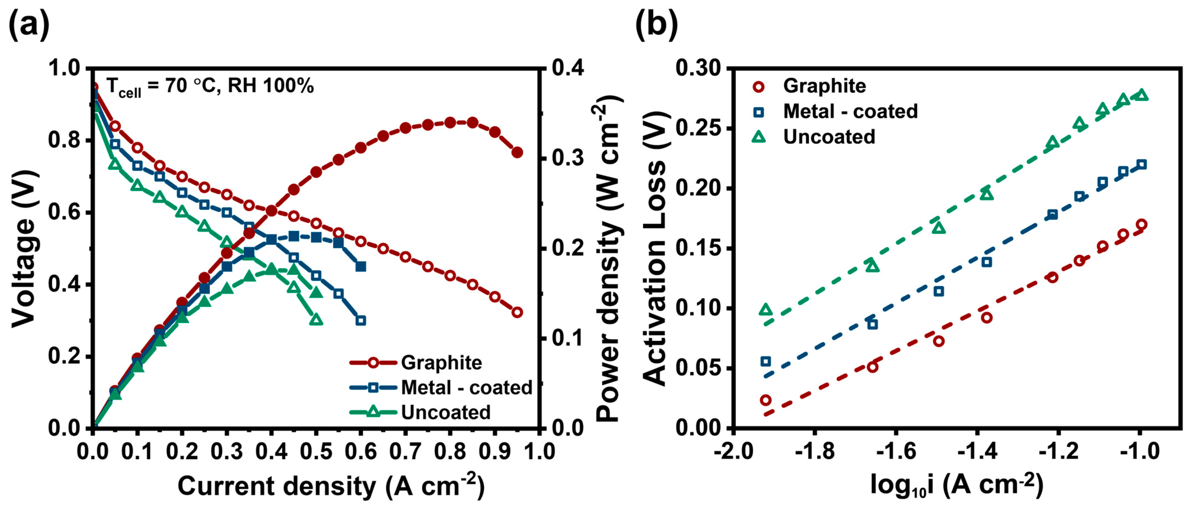
The polarization curves of PEMFCs with graphite, uncoated 3D-printed, and metal-coated 3D-printed flow-field plates are presented in Figure 4a. The open-circuit voltage (OCV) is 0.948 V for the cell with graphite plates, 0.872 V with pristine 3D-printed plates, and 0.928 V with metal-coated 3D-printed flow-field plates. In general, products prepared using fused deposition modeling 3D printers exhibit lower densities than those fabricated using alternative mass production processes, such as injection molding [42,43]. Consequently, the reduced density of the 3D-printed flow-field plates results in leakage of hydrogen or air, thereby leading to a diminished OCV. However, the fuel cell with the metal-coated 3D-printed flow-field plate exhibits an almost identical OCV, i.e., the difference is 20 mV. In previous studies on low-temperature solid oxide fuel cells (LT-SOFCs), the sputtering process is widely used to fabricate dense and defect-free oxide electrolytes with a thickness of hundreds of nanometers [44]. In particular, the oxide electrolytes reported in [44], with thicknesses of approximately 500 nm, effectively prevented hydrogen leakage. Therefore, it is hypothesized that the presence of a dense Ni adhesion layer and a dense Au current-collecting layer, with thicknesses of 420 nm and 360 nm, respectively, contributes to the prevention of hydrogen or air leakage. Accordingly, the leak from the cell is negligible. As illustrated in Figure 4a, significant voltage reduction gradients are observed in fuel cells with different flow-field plates in the mid-current density region. These gradients are associated with the ohmic resistance of the fuel cells. The ohmic resistance (Rohmic) of a fuel cell is determined by the charge transfer path, which includes both ion and electron charge transfers [17].
η o h m i c = i R o h m i c = i R i o n i c + R e l e c
Rohmic is defined as the total ohmic resistance of a fuel cell, Rionic represents the ohmic resistance related to ion charge transfer, and Relec denotes the ohmic resistance associated with electron charge transfer. Given that nearly identical MEAs were used, it is hypothesized that variations in Rionic due to ion transfer are negligible. Therefore, the observed ohmic resistance, that is, the gradients in the j-V curves, originates from Relec, which is related to the electron charge transfer. As previously mentioned, electronic charge transfer pathways exhibit significant dependence on the type of flow-field plate. In pristine 3D-printed flow-field plates, a wire is employed for current collection, restricting current collection to the vicinity of the wire. As a result, electron collection and conduction are limited, leading to severe ohmic resistance. However, in metal-coated 3D-printed flow-field plates, electrons are collected across the entire surface of the flow-field plate and subsequently conducted through a thin surface coating layer with a thickness of 1 nm.
For graphite flow-field plates, electrons are also collected across the entire surface and then conducted through the graphite material. In other words, the total length of the electron conduction path in graphite flow-field plates is significantly shorter than that in other flow-field plates. Consequently, variations in electron collection and conduction, depending on the flow-field plate configuration, result in different Rohmic. Among the three, Rohmic is highest in uncoated 3D-printed flow-field plates, lowest in graphite flow-field plates, and intermediate in metal-coated 3D-printed flow-field plates. These results confirm that the voltage gradient in the medium current density region follows the order of Rohmic.
Figure 4b presents the Tafel plot. The uncoated flow-field plate exhibits the highest activation loss, followed by the metal-coated and graphite flow-field plates, respectively.
j 0 = j 0 A A
In Equation (2), j 0 and A represent the intrinsic exchange current density and the area of a perfectly flat electrode surface, respectively. The effective reaction area (A) is defined as the area where the electrolyte, reactants, and electrically connected catalyst come into contact. It is the area where the fuel cell reaction occurs [17].
As shown in Equation (2) j 0 is influenced by the effective reaction area. In this experiment, it is hypothesized that the effective reaction area of the fuel cell differs in each case due to variations in the electrically connected catalyst regions. As the surface roughness of the flow-field plate increases, the contact area between the catalyst, GDL, and flow-field plate decreases, thereby reducing the number of electrically connected catalyst areas [45]. The graphite flow-field plate exhibits a flat and dense surface. In contrast, the metal-coated 3D-printed flow-field plate exhibits a reduction in surface irregularities due to the presence of the gold layer, compared to the uncoated 3D-printed flow-field plate. The 3D-printed flow-field plates without additional surface modifications exhibit the highest number of surface irregularities. Furthermore, the insertion of an electric wire for electricity collection supports the hypothesis that the electrically connected catalyst area is significantly more constrained in the fuel cell with the uncoated 3D-printed flow-field plate than in those with the other two types of flow-field plates. Therefore, it is assumed that the graphite flow-field plate with the smoothest surface has the largest effective reaction area, followed by the metal-coated 3D-printed flow-field plate and the uncoated 3D-printed flow-field plate. A comparison of the exchange current density, j 0 can be made by evaluating the effective reaction area using Equation (2) [22]. Furthermore, as demonstrated in Equation (3), the difference in j 0 , due to the effective reaction area, leads to a variation in ηact. Additionally, an increase in j 0 is associated with a decrease in ηact [46]. Equation (3) represents the activation overvoltage as a simplified Butler–Volmer equation, commonly known as the Tafel equation.
η a c t = R T α n F ln j j 0
Therefore, it is assumed that the magnitude of ηact is presumed to follow the order, from largest to smallest, of the uncoated 3D-printed flow-field plate, the metal-coated 3D-printed flow-field plate, and the graphite flow-field plate. The rough surface of the 3D-printed flow-field plate, as identified in Figure 1, is presumed to exacerbate the performance of PEMFCs utilizing the uncoated 3D-printed flow-field plate. In addition, it is assumed that the leakage of reactants in the uncoated flow-field plate is more severe compared to the metal-coated flow-field plate, resulting in a significantly lower concentration of reactants in the catalyst layer, which likely causes a decrease in j 0 and an increase in ηact. The observed performance degradation appears to be attributed not to the limitations of the 3D-printed flow-field plate itself but rather to the inherent resolution constraints of the 3D printer.
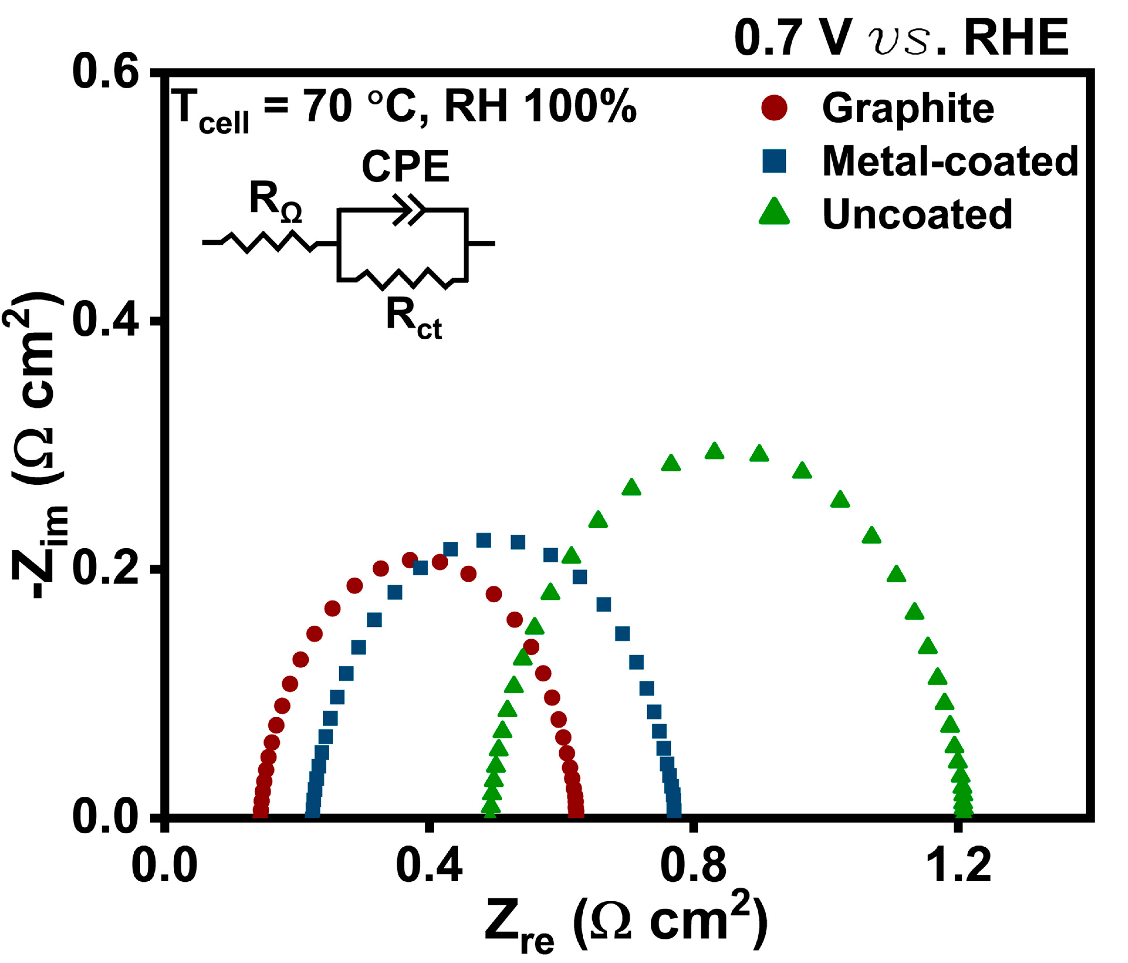
As illustrated in Figure 5, the Nyquist plots of fuel cells with different flow-field plates were measured at 0.7 V. In general, the intersection point with the reference axis represents the ohmic resistance (Rohmic)of the fuel cell [22]. Therefore, Rohmic appears to be influenced by the flow-field plate. As shown in Figure 5, the graphite flow-field plate exhibits a Rohmic of 0.143 Ω·cm2, the metal-coated 3D-printed flow-field plate demonstrates 0.199 Ω·cm2, and the uncoated 3D-printed flow-field plate shows 0.455 Ω·cm2. The results of this study indicate that the Rohmic follows the order of magnitude, from largest to smallest, as follows: uncoated 3D-printed flow-field plate, metal-coated 3D-printed flow-field plate, and graphite flow-field plate. This trend is consistent with the slope of the j–V curve in Figure 4a.
As illustrated in Figure 6, the peak power density is calculated as a function of weight and reaction area. The peak power density per unit weight is determined by considering only the weight of the flow-field plate to highlight the variations caused by the flow-field plate. The uncoated 3D-printed flow-field plate, which is most significantly affected by the two losses, exhibits the lowest peak power density per reaction area, measured at 180 mW/cm2. The peak power density per reaction area of the metal-coated 3D-printed flow-field plate increases to 213 mW/cm2, representing an 18.3% improvement compared to the fuel cell with the uncoated 3D-printed flow-field plate, due to the influence of the deposited Au current collection layer. In addition, the fuel cell with the graphite flow-field plate exhibits the highest peak power density per reaction area, reaching 341 mW/cm2. However, in terms of power density per unit weight of the flow-field plate, unlike the results obtained for the reaction area, the metal-coated 3D-printed flow-field plate exhibits the highest output of 5.21 mW/g, whereas the graphite flow-field plate demonstrates the lowest power density per unit weight at 2.78 mW/g. Despite exhibiting a lower power density per reaction area than the PEMFC with the graphite flow-field plate, the metal-coated 3D-printed flow-field plate demonstrates its capability to achieve the optimal power density per unit mass, exhibiting a 46.6% enhancement over the fuel cell with the graphite flow-field plate. The peak power density per cost ratio of the metal-coated sample is measured to be approximately one-third of that of the graphite sample. This is primarily attributed to the high cost of the gold sputtering target. This issue can be addressed by optimizing the thickness of the gold layer. Furthermore, it is speculated that this limitation can be mitigated by using alternative sputtering targets, such as stainless steel or nickel alloy, instead of gold.
As stated by Blunk et al., the presence of more than 30 wt% graphite within the bipolar plate, a composite material comprising polymer and graphite, has been demonstrated to result in a notable enhancement in H2 permeation [47]. In other words, there is a limit to how thin the graphite flow-field plate can be fabricated. In contrast, for the 3D-printed flow-field plate, the limitation on reducing the thickness of the flow-field plate is relatively mitigated compared to that of the graphite flow-field plate. This indicates that the metal-coated 3D-printed flow-field plate is less dense than graphite and can be manufactured thinner than the graphite flow-field plate.

4. Conclusions

In this experiment, lightweight PEMFCs were fabricated for portable power sources by varying the material of the flow-field plate. A graphite flow-field plate PEMFC, a metal-coated 3D-printed flow-field plate PEMFC, and an uncoated 3D-printed flow-field plate PEMFC were manufactured and analyzed using j-V curves, j-power curves, and EIS data. The metal-coated and uncoated 3D-printed flow-field plate PEMFCs showed a lower power density per reaction area than the conventional graphite flow-field plate PEMFC. However, in terms of power density per unit weight, which is one of the most critical factors for portable power sources, the metal-coated 3D-printed flow-field plate PEMFC achieved a significantly higher power density than PEMFCs with any other plate. The lower power density per reaction area observed in the metal-coated and uncoated 3D-printed flow-field plate PEMFCs, compared to that of the graphite flow-field plate PEMFC, is attributed to the rough surface and high electrical resistance of the 3D-printed flow-field plates. These factors contributed to an increase in both ηact and ηohmic. In future studies, the factors influencing power density should be further investigated by considering surface roughness and flow-field plate thickness as key variables.

Author Contributions

Conceptualization, D.K.; Methodology, G.K.; Validation, D.K., J.N. and J.K.; Investigation, D.K., G.K., J.N. and H.K.; Data curation, H.K. and J.K.; Writing—original draft, G.K. and J.N.; Writing—review & editing, G.K. and J.N.; Visualization, D.K. and H.K.; Supervision, G.C. and T.P.; Project administration, G.C. and T.P. All authors have read and agreed to the published version of the manuscript.

Funding

This work was financially supported by NRF grants (RS-2023-00209146) and (RS-2023-00213741) funded by the Ministry of Science and ICT, Republic of Korea.

Data Availability Statement

Data are contained within the article.

Conflicts of Interest

The authors declare no conflict of interest.

References

  1. Kim, D.J.; Jo, M.J.; Nam, S.Y. A review of polymer–nanocomposite electrolyte membranes for fuel cell application. J. Ind. Eng. Chem. 2015, 21, 36–52. [Google Scholar] [CrossRef]
  2. Wang, Y.; Chen, K.S.; Mishler, J.; Cho, S.C.; Adroher, X.C. A review of polymer electrolyte membrane fuel cells: Technology, applications, and needs on fundamental research. Appl. Energy 2011, 88, 981–1007. [Google Scholar] [CrossRef]
  3. Rocha, C.; Knöri, T.; Ribeirinha, P.; Gazdzicki, P. A review on flow field design for proton exchange membrane fuel cells: Challenges to increase the active area for MW applications. Renew. Sustain. Energy Rev. 2024, 192, 114198. [Google Scholar] [CrossRef]
  4. Parekh, A. Recent developments of proton exchange membranes for PEMFC: A review. Front. Energy Res. 2022, 10, 956132. [Google Scholar] [CrossRef]
  5. Kraytsberg, A.; Ein-Eli, Y. Review of advanced materials for proton exchange membrane fuel cells. Energy Fuels 2014, 28, 7303–7330. [Google Scholar] [CrossRef]
  6. Ahmad, S.; Nawaz, T.; Ali, A.; Orhan, M.F.; Samreen, A.; Kannan, A.M. An overview of proton exchange membranes for fuel cells: Materials and manufacturing. Int. J. Hydrogen Energy 2022, 47, 19086–19131. [Google Scholar] [CrossRef]
  7. Tsuchiya, H.; Kobayashi, O. Mass production cost of PEM fuel cell by learning curve. Int. J. Hydrogen Energy 2004, 29, 985–990. [Google Scholar] [CrossRef]
  8. Gao, X.; Chen, J.; Xu, R.; Zhen, Z.; Zeng, X.; Chen, X.; Cui, L. Research progress and prospect of the materials of bipolar plates for proton exchange membrane fuel cells (PEMFCs). Int. J. Hydrogen Energy 2024, 50, 711–743. [Google Scholar] [CrossRef]
  9. Brakni, O.; Kerkoub, Y.; Amrouche, F.; Mohammedi, A.; Ziari, Y.K. CFD investigation of the effect of flow field channel design based on constriction and enlargement configurations on PEMFC performance. Fuel 2024, 357, 129920. [Google Scholar] [CrossRef]
  10. Ghasabehi, M.; Jabbary, A.; Shams, M. Cathode side transport phenomena investigation and Multi-Objective optimization of a tapered parallel flow field PEMFC. Energy Convers. Manag. 2022, 265, 115761. [Google Scholar] [CrossRef]
  11. Ashrafi, M.; Shams, M. The effects of flow-field orientation on water management in PEM fuel cells with serpentine channels. Appl. Energy 2017, 208, 1083–1096. [Google Scholar] [CrossRef]
  12. Sauermoser, M.; Kizilova, N.; Pollet, B.G.; Kjelstrup, S. Flow field patterns for proton exchange membrane fuel cells. Front. Energy Res. 2020, 8, 13. [Google Scholar] [CrossRef]
  13. Ashrafi, M.; Kanani, H.; Shams, M. Numerical and experimental study of two-phase flow uniformity in channels of parallel PEM fuel cells with modified Z-type flow-fields. Energy 2018, 147, 317–328. [Google Scholar] [CrossRef]
  14. Wang, H.; Turner, J. Reviewing metallic PEMFC bipolar plates. Fuel Cells 2010, 10, 510–519. [Google Scholar] [CrossRef]
  15. Xu, Z.; Qiu, D.; Yi, P.; Peng, L.; Lai, X. Towards mass applications: A review on the challenges and developments in metallic bipolar plates for PEMFC. Prog. Nat. Sci. Mater. Int. 2020, 30, 815–824. [Google Scholar] [CrossRef]
  16. Hermann, A.; Chaudhuri, T.; Spagnol, P. Bipolar plates for PEM fuel cells: A review. Int. J. Hydrogen Energy 2005, 30, 1297–1302. [Google Scholar] [CrossRef]
  17. O’hayre, R.; Cha, S.-W.; Colella, W.; Prinz, F.B. Fuel Cell Fundamentals; John Wiley & Sons: Hoboken, NJ, USA, 2016. [Google Scholar]
  18. Wu, S.; Yang, W.; Yan, H.; Zuo, X.; Cao, Z.; Li, H.; Shi, M.; Chen, H. A review of modified metal bipolar plates for proton exchange membrane fuel cells. Int. J. Hydrogen Energy 2021, 46, 8672–8701. [Google Scholar] [CrossRef]
  19. Li, X.; Sabir, I. Review of bipolar plates in PEM fuel cells: Flow-field designs. Int. J. Hydrogen Energy 2005, 30, 359–371. [Google Scholar] [CrossRef]
  20. Wang, X.; Qu, Z.; Yang, H.; Zhang, G.; Zhang, Y.; Liu, C. Collective enhancements on thermal-electrical and mechanical properties of graphite-based composite bipolar plates through the coupled manipulations of molding and impregnation pressures. Membranes 2022, 12, 222. [Google Scholar] [CrossRef]
  21. Jeong, K.I.; Oh, J.; Song, S.A.; Lee, D.; Kim, S.S. A review of composite bipolar plates in proton exchange membrane fuel cells: Electrical properties and gas permeability. Compos. Struct. 2021, 262, 113617. [Google Scholar] [CrossRef]
  22. Pitchiya, A.P.; Le, N.-T.; Putnam, Z.A.; Harrington, M.; Krishnan, S. Microporous graphite composites of tailorable porosity, surface wettability, and water permeability for fuel cell bipolar plates. Ind. Eng. Chem. Res. 2021, 60, 10203–10216. [Google Scholar] [CrossRef]
  23. Wenkai, L.; Zhiyong, X.; Haodong, Z. Current status of research on composite bipolar plates for proton exchange membrane fuel cells (PEMFCs): Nanofillers and structure optimization. RSC Adv. 2024, 14, 7172–7194. [Google Scholar] [CrossRef] [PubMed]
  24. Hung, Y.; Tawfik, H.; Mahajan, D. Effect of terminal design and bipolar plate material on PEM fuel cell performance. Smart Grid Renew. Energy 2013, 4, 28123. [Google Scholar] [CrossRef]
  25. Li, W.; Xie, Z.; Qiu, S.; Zeng, H.; Liu, M.; Wu, G. Improved performance of composite bipolar plates for PEMFC modified by homogeneously dispersed multi-walled carbon nanotube networks prepared by in situ chemical deposition. Nanomaterials 2023, 13, 365. [Google Scholar] [CrossRef]
  26. Hickmann, T.; Zielinski, O. Bipolar Plates: Different Materials and Processing Methods for Their Usage in Fuel Cells. E3S Web of Conf. 2020, 160, 01002. [Google Scholar]
  27. Kim, K.H.; Lim, J.W.; Kim, M. Development of carbon fabric/graphite hybrid bipolar plate for PEMFC. Compos. Struct. 2013, 98, 103–110. [Google Scholar] [CrossRef]
  28. Akiki, T.; Accary, G.; Charon, W.; Kouta, R. Influence of Local Porosity, Local Permeability, and Contact Resistance Between the Gas Diffusion Layer and the Bipolar Plate, on the Performances of a Polymer Electrolyte Membrane Fuel Cell. In Proceedings of the CCCA12, Marseille, France, 6–8 December 2012; IEEE: Piscataway, NJ, USA, 2012; pp. 1–6. [Google Scholar]
  29. Chung, C.-Y.; Chen, S.-K.; Chiu, P.-J.; Chang, M.-H.; Hung, T.-T.; Ko, T.-H. Carbon film-coated 304 stainless steel as PEMFC bipolar plate. J. Power Sources 2008, 176, 276–281. [Google Scholar] [CrossRef]
  30. Dhakate, S.; Mathur, R.; Kakati, B.; Dhami, T. Properties of graphite-composite bipolar plate prepared by compression molding technique for PEM fuel cell. Int. J. Hydrogen Energy 2007, 32, 4537–4543. [Google Scholar] [CrossRef]
  31. Wu, S.-D.; Chiou, A.-H. The study on a new method of preparing PMMA forming composite bipolar plate. Sci. Rep. 2021, 11, 8753. [Google Scholar] [CrossRef]
  32. Jang, G.-E.; Cho, G.-Y. Effects of Ag current collecting layer fabricated by sputter for 3D-printed polymer bipolar plate of ultra-light polymer electrolyte membrane fuel cells. Sustainability 2022, 14, 2997. [Google Scholar] [CrossRef]
  33. Balogh, M.P.; Dadheech, G.V.; Irish, N.P.; Tessema, M.M.; Miller, D.P.; Abd Elhamid, M.H. Method of Depositing Durable Thin Gold Coating on Fuel Cell Bipolar Plates. U.S. Patent No. 8,778,562, 15 July 2014. [Google Scholar]
  34. Dorjgotov, A.; Jeon, Y.; Hwang, J.; Ulziidelger, B.; Kim, H.S.; Han, B.; Shul, Y.-G. Synthesis of durable small-sized bilayer Au@ Pt nanoparticles for high performance PEMFC catalysts. Electrochim. Acta 2017, 228, 389–397. [Google Scholar] [CrossRef]
  35. Marinoiu, A.; Andrulevicius, M.; Tamuleviciene, A.; Tamulevicius, T.; Raceanu, M.; Varlam, M. Synthesis of well dispersed gold nanoparticles on reduced graphene oxide and application in PEM fuel cells. Appl. Surf. Sci. 2020, 504, 144511. [Google Scholar] [CrossRef]
  36. Fan, H.-Q.; Wu, Y.-M.; Su, S.; Shi, D.-D.; Wang, X.-Z.; Behnamian, Y.; Zhang, J.-Y.; Li, Q. Solution acidity and temperature induced anodic dissolution and degradation of through-plane electrical conductivity of Au/TiN coated metal bipolar plates used in PEMFC. Energy 2022, 254, 124453. [Google Scholar] [CrossRef]
  37. Marinoiu, A.; Raceanu, M.; Andrulevicius, M.; Tamuleviciene, A.; Tamulevicius, T.; Nica, S.; Bala, D.; Varlam, M. Low-cost preparation method of well dispersed gold nanoparticles on reduced graphene oxide and electrocatalytic stability in PEM fuel cell. Arab. J. Chem. 2020, 13, 3585–3600. [Google Scholar] [CrossRef]
  38. Liang, S.; Schwartzkopf, M.; Roth, S.V.; Müller-Buschbaum, P. State of the art of ultra-thin gold layers: Formation fundamentals and applications. Nanoscale Adv. 2022, 4, 2533–2560. [Google Scholar] [CrossRef]
  39. Olivera, S.; Muralidhara, H.B.; Venkatesh, K.; Gopalakrishna, K.; Vivek, C.S. Plating on acrylonitrile–butadiene–styrene (ABS) plastic: A review. J. Mater. Sci. 2016, 51, 3657–3674. [Google Scholar] [CrossRef]
  40. Coronell, D.; Egan, E.; Hamilton, G.; Jain, A.; Venkatraman, R.; Weitzman, B. Monte Carlo simulations of sputter deposition and step coverage of thin films. Thin Solid Film. 1998, 333, 77–81. [Google Scholar] [CrossRef]
  41. Callister, W.D.; Rethwisch, D.G. Materials Science and Engineering: An Introduction; Wiley New York: New York, NY, USA, 1999. [Google Scholar]
  42. Ji, C.; Loh, N.; Khor, K.; Tor, S. Sintering study of 316L stainless steel metal injection molding parts using Taguchi method: Final density. Mater. Sci. Eng. A 2001, 311, 74–82. [Google Scholar] [CrossRef]
  43. Heidari-Rarani, M.; Rafiee-Afarani, M.; Zahedi, A. Mechanical characterization of FDM 3D printing of continuous carbon fiber reinforced PLA composites. Compos. Part B Eng. 2019, 175, 107147. [Google Scholar] [CrossRef]
  44. Cho, G.Y.; Lee, Y.H.; Hong, S.W.; Bae, J.; An, J.; Kim, Y.B.; Cha, S.W. High-performance thin film solid oxide fuel cells with scandia-stabilized zirconia (ScSZ) thin film electrolyte. Int. J. Hydrogen Energy 2015, 40, 15704–15708. [Google Scholar] [CrossRef]
  45. Lin, C.-H. Surface roughness effect on the metallic bipolar plates of a proton exchange membrane fuel cell. Appl. Energy 2013, 104, 898–904. [Google Scholar] [CrossRef]
  46. Bard, A.J.; Faulkner, L.R.; White, H.S. Electrochemical Methods: Fundamentals and Applications; John Wiley & Sons: Hoboken, NJ, USA, 2022. [Google Scholar]
  47. Blunk, R.; Zhong, F.; Owens, J. Automotive composite fuel cell bipolar plates: Hydrogen permeation concerns. J. Power Sources 2006, 159, 533–542. [Google Scholar] [CrossRef]
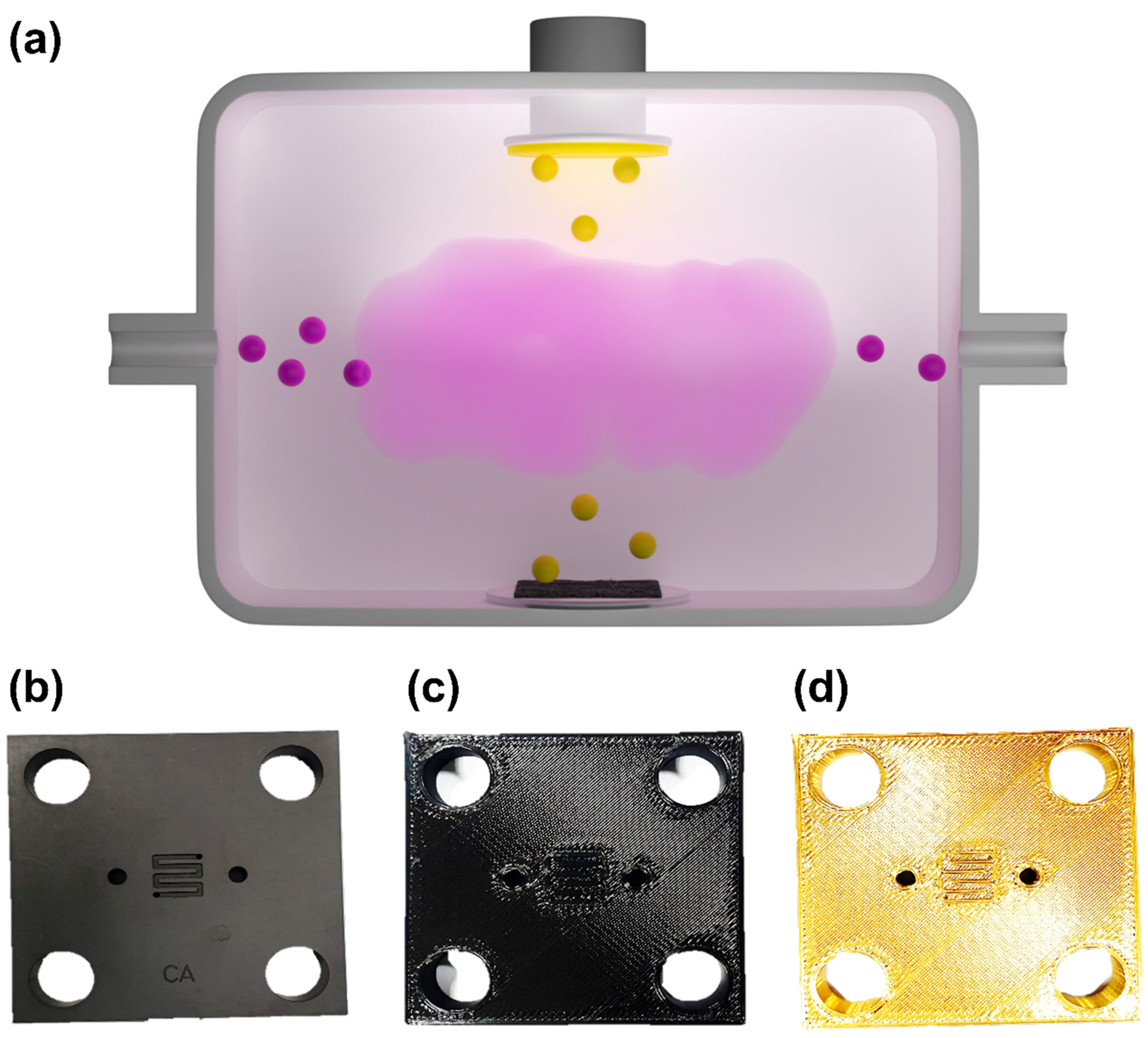
Figure 1. (a) Schematics of the sputtering process. Images of the (b) graphite flow-field plate, (c) uncoated 3D-printed flow-field plate, and (d) metal-coated 3D-printed flow-field plate.
Energies 18 01533 g001
Figure 2. Surface and cross-sectional SEM images of the metal-coated 3D-printed flow-field plate. (a) The surface of the channel, (b) of the rib.
Energies 18 01533 g002
Figure 3. Variation in coating thickness across different regions of the flow field plate.
Energies 18 01533 g003
Figure 4. Polarization curves and Tafel plot of the fuel cells with graphite, the uncoated 3D-printed, and the metal-coated 3D-printed flow-field plate. (a) Polarization curves (b) Tafel plot.
Energies 18 01533 g004
Figure 5. EIS analysis at 0.7 V (versus RHE) of the fuel cells with graphite, the uncoated 3D-printed, and the metal-coated 3D-printed flow-field plate.
Energies 18 01533 g005
Figure 6. Comparison of the peak power density per area (W/cm2), peak power density per mass (W/g), and peak power density per cost (W/$) of the fuel cells with graphite, the uncoated 3D-printed, and the metal-coated 3D-printed flow-field plate. (a) Peak power density per area(W/cm2) (b) Peak power density per mass (W/g) (c) Peak power density per cost (W/$).
Energies 18 01533 g006
Disclaimer/Publisher’s Note: The statements, opinions and data contained in all publications are solely those of the individual author(s) and contributor(s) and not of MDPI and/or the editor(s). MDPI and/or the editor(s) disclaim responsibility for any injury to people or property resulting from any ideas, methods, instructions or products referred to in the content.