Abstract
To fully recover abundant waste heat and reduce the operation cost in liquid-cooled data centers, a Carnot battery consisting of a heat pump (HP) and organic Rankine cycle (ORC) is proposed. Due to the existence of different cycle states for HPs and ORCs, four different cycle combinations are considered. To evaluate and compare their performances, thermo-economic models are developed. Under the design conditions, the optimal working fluid combinations are first determined for each battery. On this basis, thermodynamic and economic performances of the four batteries are analyzed in detail. The results indicate that the system consisting of a subcritical HP/transcritical ORC achieves the highest round-trip efficiency at 76%. Notably, the round-trip efficiency of the system can exceed 100% at low ORC condensing temperatures. Additionally, the system cost is about 767–796 USD/kW∙h, depending on the cycle combinations. Furthermore, the effects of operating parameters on system performances are also investigated. Finally, with the objective of maximum round-trip efficiency, key parameters of four batteries are optimized. The results reveal that the system with a subcritical HP/subcritical ORC attains a maximum round-trip efficiency of 83% after optimization. These research results contribute to the development of green data centers and the reduction of power costs.
1. Introduction
1.1. Background
With the construction of the digital economy, the demand for data storage and processing has surged globally, leading to an expansion in the scale of data centers (DCs). It is reported that the total number of DC racks in China has exceeded 8.8 million by the end of September 2024 [1]. Faced with massive data calculations, DC servers require a large amount of electricity (in kW∙h). It is estimated that DCs consume up to 3% of global electricity today and are expected to reach 4% by 2030 [2]. Notably, the electrical energy consumed in DCs is ultimately converted into heat, with cooling operations alone consuming up to 40% of the overall DC electricity [3]. Moreover, if the waste heat generated by data centers is directly discharged to the outside environment, the waste heat is not effectively utilized, which may cause urban heat island effect. Thus, effectively utilizing this considerable amount of waste heat is crucial for reducing energy dissipation and minimizing air pollution [4]. So far, the main obstacle to recovering the waste heat of traditional DCs is the lower waste heat temperature [5]. Therefore, liquid cooling technology has been implemented in the DC industry [6]. It utilizes Fluorinert electronic liquids to achieve point-to-point cooling of servers and meet the heat dissipation requirements of high power-density racks. Furthermore, the high thermal conductivity of liquid-cooled coolant reduces the temperature difference between the coolant and servers, allowing the coolant outlet temperature to reach up to 75 °C [7].
1.2. Waste Heat Recovery of DCs
The uniform distribution and uninterrupted operation of servers make DCs a stable and reliable heat source. Generally, the waste heat of DCs is mainly used for district heating (DH) [8]. For instance, Lu et al. [9] analyzed the potential of waste heat recovery for DH in a Finnish data center on the basis of real operation and concluded that the waste heat of a 1 MW DC could satisfy the heat demand for an over 30,000 m2 non-domestic building per year. Davies et al. [10] investigated the utilization of heat pumps (HPs) to elevate a data center’s waste heat temperature to meet the DH requirements. The analysis focused on the feasibility of applying the data center waste heat for DH in London. It was found that coupling a 3.5 MW data center with a heat recovery system could lead to savings of over 4000 tons of CO2 and nearly GBP 1,000,000 per year. However, the team also pointed out that the potential of DC waste heat for DH is associated with the geographical location of DCs and consumers, and the DH project is not suitable for warm or hot climate areas [10]. Moreover, because of the intermittent heating demand caused by seasonal restrictions, the utilization rate of the waste heat in heating is relatively low from a year-round perspective. Therefore, how to further recover the waste heat of DCs is worthy of investigation.
To fully recover the waste heat generated by DCs all year round, researchers proposed employing the power cycle to produce electricity from the waste heat. In the field of low-grade waste heat utilization, the organic Rankine cycle (ORC) has been widely used due to its benefits of high efficiency, low cost, and simple structure. For instance, Ebrahimi et al. [7] evaluated the suitability of each currently available DC waste heat recovery technology. They found that the ORC is the most thermodynamically and economically promising technology for waste heat reuse in DCs. Chen et al. [11] proposed a cogeneration system with different configurations driven by DC waste heat. The system utilized two-phase cooling technology to absorb the waste heat and generated electricity through a power cycle. It was proved that a system integrated ORC and absorption refrigeration cycle was the most promising heat recovery system, with an energy efficiency of 58.13%. In this regard, an HP is introduced to upgrade the low temperature of DC waste heat, thereby improving the thermal efficiency of ORCs. Ebrahimi et al. [12] employed an ORC system to recover DC waste heat, where the waste heat was first increased in temperature through HPs. The results indicated that at a water supply temperature of 60 °C, the electricity consumed by an HP can be fully provided by the electricity generated by an ORC, with a payback period of 4–8 years. Marshall et al. [13] used an HP-ORC cooling system to replace traditional air-source vapor compression chillers for cooling DC servers and assessed the economic performance of both cooling systems. Results showed that an HP-ORC cooling system was found to be up to 65% less expensive than air-source vapor compression chillers.
1.3. Energy Storage
Besides recovering the waste heat, due to the 24 h uninterrupted operation of DCs, the electricity cost is too high during peak hours. Therefore, the operation cost can also be reduced by taking advantage of the peak–valley price difference of electricity. This requires configuring an energy storage system for DCs [14]. During the period of electricity valleys, the system stores redundant and cheap electricity. During the period of electricity peaks, the system is capable of converting stored thermal energy into electricity for use in DCs, thus avoiding the use of high-price electricity. In addition to reducing the operation cost, configuring the energy storage system in DCs can also contribute to long-term sustainability by promoting the direct electricity supply of renewable energy to data centers. This reduces dependency on fossil fuels, mitigates environmental impacts, and fosters the development of green data centers. Nowadays, electrochemical energy storage is relatively mature and has been widely used in DCs. However, considering the high cost and short cycle life [15] of electrochemical energy storage, which is unsuitable for large-scale and long-term energy storage, it is generally only used as a backup power source for data centers [16].
With the continuous expansion of DC scales, energy storage of DCs has gradually developed into large-scale energy storage (100 MW level [17]). Among the large-scale energy storage options in DCs, a Carnot battery is a potential option [18]. In terms of energy storage principle, a Carnot battery mainly uses thermal storage to achieve the purpose of storing electricity. Thus, a Carnot battery is also called “Pumped Thermal Energy Storage” [19]. In the charging process, the electricity is consumed by driving the electric heating process, so that the heat can be moved from the low-temperature side to the high-temperature side, and meanwhile the thermal energy is stored. In the discharging process, the stored energy is used to drive the power cycle to output electricity, so as to achieve the spatiotemporal transfer of electricity [20]. Targeting different application scenarios, the charging process can be accomplished with an HP, an electric heater, or any other technology. Likewise, in the discharging process, any heat engine technology, including Rankine cycles and Brayton cycles, can be used [18]. Compared with electrochemical energy storage, a Carnot battery has a relatively high security, low cost, and high efficiency [21]. Therefore, research has been conducted to explore the performance of Carnot batteries.
In terms of an HP-ORC Carnot battery, Yu et al. [22] designed three subcritical systems employing R1233zd(E) as a working fluid, namely a basic HP-ORC, reversible HP-ORC, and reversible HP-ORC with shared turbomachinery. Comparison results showed that the reversible HP-ORC is better thermo-economically when considering energy efficiency, exergy efficiency, and LCOS comprehensively. Steger et al. [23] designed a reversible HP-ORC Carnot battery operating in a subcritical state and used a multi-criteria decision-making method to determine the thermal storage temperature and working fluid. The results indicated that when using R1233zd(E), the maximum RTE (59%) of the battery can be obtained at a storage temperature of 120 °C. Additionally, to improve the overall performance of the Carnot battery, extra heat sources were also introduced. For instance, Scharrer et al. [24] proposed a reversible HP (20 kW)-ORC (7–13 kW) Carnot battery coupled with photovoltaics, and the used working fluid was R1233zd(E). Under German market conditions, researchers explored the feasibility of using a Carnot battery to power residential units. Research showed that the system can power a community of 10–30 houses with an investment payback period of 14 years. Staub et al. [25] developed a reversible and subcritical HP-ORC Carnot battery combined with waste heat sources. The working fluid R365mfc was considered. Numerical simulation results outlined that the RTE of the system in the megawatt range can reach up to 70%, when the efficiencies of turbines and compressors are higher. Dumont et al. [26] described a thermally integrated reversible HP-ORC Carnot battery using R1233zd(E) as a working fluid. At an air temperature of 15 °C and waste heat temperature of 75 °C, the RTE of the system reaches 101%. Frate et al. [27] designed two different layouts for a subcritical HP-ORC Carnot battery with low-grade thermal energy integration, a basic layout and a layout with internal regeneration. Meanwhile, optimal working fluid combinations for the two layouts were screened. Moreover, a multi-objective optimization was conducted to analyze and compare the optimal theoretical performances of the two different layouts. The results indicated that the best-performing working fluid combinations are Cyclopentane–Cyclopentane and Pentane–R245fa for regenerated and non-regenerated layouts, respectively. In the multi-objective framework, the introduction of regeneration has a significant effect, which can increase RTE by 32%. Niu et al. [28] proposed an HP-ORC Carnot battery coupled with trough solar collector and constructed models of a basic Carnot battery and Carnot battery with a regenerator. Then, multi-objective optimization was carried out by TOPSIS. Results indicated that when the system with a regenerator employs working fluid R245fa-R601, the optimal LCOS and RTE can reach 0.168 USD/kW∙h and 454.14%, respectively.
In the above existing research, research on subcritical Carnot batteries has been more prevalent, while studies on transcritical configurations remain relatively limited in certain aspects. While some research examines working fluid selection, it primarily optimizes fluids for specific layouts rather than systematically analyzing the impact of cycle state combinations on overall system performance. Additionally, the aforementioned research has demonstrated the effectiveness of the Carnot battery by coupling with low-grade waste heat, but their application scenarios are largely confined to residential and industrial settings, with little attention given to DCs. Theoretically, an HP-ORC Carnot battery is easy to combine with the energy system of the user side to achieve electricity storage. Therefore, for the energy storage requirements of DCs, a Carnot battery can recover the waste heat of the DC by HPs and produce electricity by power cycles, providing a promising solution for energy recovery and storage.
1.4. Purpose of This Study
Based on the above literature review, to the best of the authors’ knowledge, few studies have investigated the performances of Carnot batteries under the application scenario of DCs. Therefore, this paper presents an HP-ORC Carnot battery to promote the development of green data centers and reduce the operation cost of liquid-cooled DCs. The battery employs HPs to extract the waste heat generated by the DC, and the electricity is stored in the form of high-temperature thermal energy. When electricity is needed, the stored thermal energy drives the ORC to output electricity under the environmental cold source.
To comprehensively investigate the performances of a Carnot battery coupled with a DC, thermo-economic models are developed. Meanwhile, considering the fact that the performances of HPs and ORCs are closely related to the operation conditions and working fluids, four different cycle combinations of HP and ORC are investigated here, and different fluids for HPs and ORCs are adopted to screen the optimal fluids for each battery. On this basis, the performance of these four batteries is first analyzed and compared under the design conditions to explore the cycle combinations with optimal performance. Thereafter, the effects of key parameters on system performance are revealed. Finally, the corresponding operating parameters under optimal operating conditions are obtained with RTE as the optimization target, and the performance of the four batteries is analyzed and discussed.
The main innovations of this study are as follows:
- (1)
- Investigating the feasibility and techno-economic benefits of employing Carnot batteries for waste heat recovery in liquid-cooled DCs.
- (2)
- Analyzing different HP-ORC cycle state combinations by selecting appropriate working fluid combinations to evaluate system performance.
- (3)
- Optimizing the proposed Carnot battery with RTE as the optimization target.
2. System Description
Under the same cold and heat source conditions, different working fluids will exhibit different cycle states due to their different thermodynamic properties. Theoretically, both HPs and ORCs can operate in the subcritical or transcritical regions of working fluids. Therefore, four types of Carnot batteries are considered in this study. The cycle combinations of four batteries are shown in Table 1.

Table 1.
Cycle combinations of four Carnot batteries.
Considering that the layouts of the system are similar, here, the layout is described by taking the subcritical HP and ORC as an example, as shown in Figure 1. It can be found that the Carnot battery consists of an HP, a thermal storage loop, and an ORC. During the charging process, the HP operates as follows: initially, the working fluid passes through Evaporator1 to absorb heat from the coolant of the liquid-cooled DC (5→2) and then flows into the Compressor to further increase the pressure and temperature (2→3). Thereafter, the fluid undergoes heat exchange with pressurized water in the Cold water tank within Condenser1 (3→4). Finally, the fluid enters the Throttle valve for further cooling and pressure reduction (4→5) before returning to Evaporator1 to complete the cycle. In the meantime, the cold water absorbs the condensation heat from the HP to become the hot water in the thermal storage loop. During the discharging process, the ORC working fluid absorbs the stored thermal energy in Evaporator2 (6→7) and then flows into the Turbine to expand and output electricity (7→8). The expanded fluid then enters Condenser2 for further cooling (8→9). Finally, the fluid is pressured by the Pump and completes the cycle (9→6). When the Carnot battery is inactive, waste heat from the DC’s liquid cooling loop is dissipated to the environment via an air-cooled Regenerator, ensuring stable thermal management.
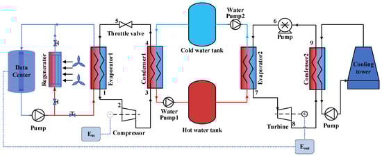
Figure 1.
Schematic diagram of the SHP-SORC.
For the four considered systems, the corresponding T- diagrams are provided in Figure 2. It can be found that when the working fluid has a higher critical temperature, the system operates in the subcritical region. This means that the HP fluid is condensed by cold water, and the ORC fluid is evaporated by hot water. Due to the fact that the temperature keeps constant in the process of phase change, the pinch points of the HP condensation and ORC evaporation are usually located at the bubble or dew point, as shown in Figure 2a. As a comparison, when the working fluid has a lower critical temperature, the state of the fluid at the highest temperature will be located at the supercritical region. Under this condition, the HP fluid is cooled by cold water, and the ORC fluid is heated by hot water, as shown in Figure 2d. Since the fluid temperature continuously varies with the heat, there is a better temperature match between working fluid and water.
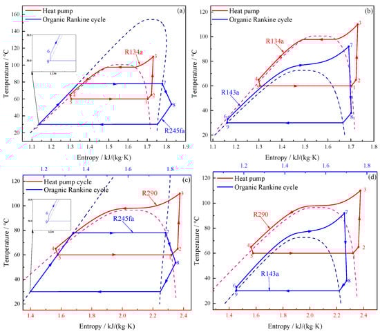
Figure 2.
T- diagrams of four Carnot batteries: (a) SHP-SORC; (b) SHP-TORC; (c) THP-SORC; (d) THP-TORC.
3. Model Development
To investigate the performances of the four Carnot batteries, thermo-economic models are developed here. Similarly, for simplicity, only SHP-SORC is taken as an example to present these models. For the other batteries, similar equations can be easily derived.
To simplify the modeling, the following assumptions are applied:
- (1)
- All components operate under steady-state conditions [29];
- (2)
- Neglect pressure drops in pipes or apparatuses [30];
- (3)
- Neglect heat loss in pipes and water tanks [23];
- (4)
- An isentropic efficiency is applied to the Turbine and the Compressor [30];
- (5)
- The throttling process is regarded as an isenthalpic process [29];
- (6)
- Neglect kinetic energy, potential energy, and frictional losses of working fluid in the system [23].
3.1. Energy Model
Based on the conservation law of mass and energy, the models for the main components in the system are, respectively, presented in Table 2.
Table 2.
Energy balance models for the proposed system.
3.2. Exergy Model
According to the second law of thermodynamics, the specific exergy at each state point in the system can be expressed by the following equation:
For the Carnot batteries, the net rate of the exergy provided by the DC waste heat is obtained by
where TDC,ave is the average temperature that the DC can provide to the HP through the liquid cooling cycle, expressed in K. It can be calculated by the coolant inlet and outlet temperatures, as shown in Equation (3).
where TDC,in and TDC,out represent the inlet and outlet temperatures of the liquid cooling loop in the DC at Evaporator 1, expressed in K.
According to the exergy balance equations, the exergy destruction in different components can be determined, as summarized in Table 3.
Table 3.
Exergy destruction in different components for the proposed system.
3.3. Economic Model
The economic analysis is a vital aspect in the actual engineering construction. The total costs of the Carnot battery proposed in this paper include the total initial investment cost and operation and maintenance costs. The initial investment costs of each component in the system are listed in Table 4.
Table 4.
Cost calculation formula of each component.
In Table 4, Ai represents the heat exchange areas; it can be calculated as
where ∆Tm is the logarithmic average temperature difference of the heat transfer process, which is defined as
where F is the correction efficiency of ∆Tm, which is assumed as value 1 in this study [36]. U represents the overall heat transfer coefficient of the heat transfer process, and the values for different working fluid pairs refer to the research results of Coker [37]. Additionally, Er is the exchange rate of the Euro and U.S. dollar, which is assumed to be 1.0854. fm and fp stand for the material factor and pressure factor of heat exchangers, expressed as 2.3 and 1.2, respectively [31].
Since the costs of the intake water and the Throttle valve are small compared to those of the other components, they are neglected in the present work [38]. In addition, the Chemical Engineering Plant Cost Index (CEPCI) for the year 2023 is used to update the purchase component cost [39]. The total initial investment cost in 2023 can be expressed as
where CEPCIref corresponds to the CEPCI value for the year in which the cost formula was referenced, and CEPCI2023 is the value of CEPCI for the year 2023.
3.4. Performance Evaluation Indexes
For the Carnot batteries, electricity is consumed by the HP to raise the temperature of DC waste heat. To evaluate the corresponding performance, COP is employed, as shown in the following equation:
The purpose of the ORC is to convert stored thermal energy into electricity for external output. ORC thermal efficiency is defined as the ratio of the net power output to heat absorption capacity; the corresponding thermal efficiency can be expressed as
where is the net power output of the ORC. It is defined as the difference between the power output of the Turbine and the power consumed by the Pump, namely
This study defines round-trip efficiency (RTE) to evaluate the electricity conversion performance of the Carnot battery. It is calculated as the ratio of the total electricity generation during the discharging process to the total electricity consumption during the charging process [40]. The expression is as follows:
The Carnot battery proposed in this study utilizes the input electricity to increase the DC waste heat temperature and stores it in the hot water tank during the charging process. Meanwhile, the pressurized water in the Cold water tank is pumped to the Hot water tank by Water pump1. Thereafter, the heat of the hot water is converted to electricity by the ORC when there is a demand for electricity. At this point, the pressurized water is pumped back to the Cold water tank via Water pump2. Hence, the exergy efficiency of the system is defined by
The total system cost of Carnot batteries can be expressed as [14]
In the formula, Cinvest is the total initial investment cost. As for other costs, the corresponding functions can be found in Table 5.
Table 5.
Cost calculation formula of the Carnot battery system.
The system cost is introduced as a normalized economic index to evaluate the economic feasibility of different Carnot battery configurations. It is defined as the total system cost divided by the total power generation (in kW∙h) of the ORC over the discharging period, given by
4. Working Conditions and Working Fluids
4.1. Working Conditions
Assume that the considered DC comprises 1000 servers, and the heat release of each server is 154 W, which is based on the DC cooling load in the low server utilization scenario proposed by Marshall et al. [13]. Meanwhile, the charging time of the Carnot battery is set to 8 h, and the discharging time is 7 h, following the electricity pricing policy of Guangzhou, China, where off-peak electricity is available from 00:00 to 08:00, and peak pricing occurs from 10:00 to 12:00 and 14:00 to 19:00 [14]. Moreover, due to the limitations of liquid cooling technology in DCs, the inlet and outlet temperatures of the coolant in Evaporator1 are set to 70 °C and 60 °C, respectively. At this time, the outlet temperature of HP working fluid in Evaporator1 is set at 65 °C, where the superheat temperature of vapor is 5 °C to avoid damage to the Compressor. For the purpose of subsequent system performance analysis, a set of parameters defining the design conditions is provided in Table 6.
Table 6.
Parameters of the Carnot batteries under design conditions.
4.2. Selection of Working Fluids
For the four Carnot batteries proposed in this study, it is necessary to carefully select working fluids due to the different critical parameters. After considering factors such as thermophysical properties, safety, and economy of working fluids commonly applied in the literature [41,42] and engineering, the 10 fluids shown in Table 7 were ultimately chosen. Moreover, properties such as molecular mass and critical temperature are also listed in the table.
Table 7.
Thermodynamic properties of working fluids.
5. System Optimization
Based on the above established thermo-economic models and design parameters, the MATLAB R2021a platform is used to develop the corresponding model code, and REFPROP 9.0 is employed to calculate the physical properties of the selected working fluids. It should be noted that in order to meet the constraint of the PPTDs, the outlet temperature of Condenser1 or Cooler1 is iterated for HPs, and the outlet temperature of Evaporator2 or Heater2 is iterated for ORCs. Taking SHP-SORC as an example, the calculation flow chart is provided in Figure 3. It can be observed that the chart mainly consists of two sections, corresponding to the calculations of HP and ORC.
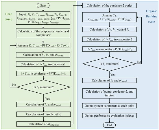
Figure 3.
Calculation flow chart of the SHP-SORC.
After evaluating the design performance of system, the optimization objective is clarified, and the operational parameters are optimized for optimal system performance. Similarly, the optimization process of SHP-SORC is described in detail below.
The optimization objective is to achieve maximum RTE. The COP should be firstly maximized to realize the objective. Compressor outlet temperature has a great influence on COP, so it is crucial to find the maximum COP by iterating the Compressor outlet temperature. Furthermore, when the Compressor outlet temperature varies, the Hot water tank temperature needs to be simultaneously varied to achieve the maximum possible heat exchange under the constraint of PPTDcond1 or PPTDc1. As shown in Figure 4, in the HP, the iteration starts with the design parameter of Compressor outlet temperature, and then the temperature range of the Hot water tank is determined accordingly. Thereafter, parameters of each point can be derived, and COP can be determined. Finally, the maximum COP is obtained by iterating the Compressor outlet temperature and Hot water tank temperature in return. After optimizing the HP, the total mass of pressurized water is regained, which is the later used in the calculation of the ORC.
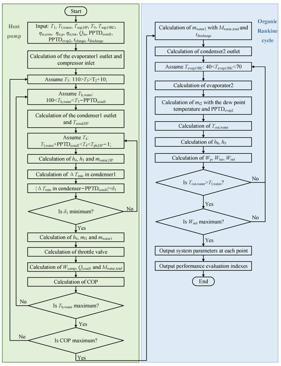
Figure 4.
System optimization chart of the SHP-SORC.
The main purpose of the ORC is to convert as much of the stored thermal energy as possible into electricity. Therefore, the optimization objective of the ORC is to maximize the net power output. In the ORC, the evaporating temperature is considered as the iterative parameter, and the superheat temperature in Evaporator2 is set at this time. As the location of the pinch point in Evaporator2 is known, the outlet temperature of pressurized water on the thermal storage loop can be obtained. The net power output is then derived under the given conditions. Finally, the evaporating temperature under the maximum net power output is calculated by satisfying the constraint of and the temperatures of pressurized water. At this point, the maximum RTE can be determined.
6. Results and Discussion
Based on the given design conditions, four batteries are firstly simulated to investigate the effects of working fluid combinations. Thereafter, the working fluid combinations that maximize system performance for each battery are identified, and the performances of the four batteries are achieved. Furthermore, the effects of key parameters on system performance for the four batteries are analyzed and compared. Finally, by comparing the performance of each battery under the design and optimized conditions, the optimization potential of each battery is determined, along with identifying the optimal battery under optimized conditions. The specific results and discussion are provided in the following subsections.
6.1. Design Performance for Different Working Fluid Combinations
As stated in Section 4.2, this study employs various working fluid combinations for each battery. The sensitivity analysis of the fluids in SHP-SORC is exhibited in Table 8. In SHP-SORC, when R134a is designated as the HP working fluid, its amalgamation with any ORC working fluid yields a superior RTE in comparison to other fluid combinations within the identical ORC working fluid configuration. Thus, R134a is chosen as the HP working fluid. The system demonstrates a maximum RTE of 62.91% when selecting the ORC working fluid R245fa. Moreover, the exergy efficiency also reaches its maximum value of 32.27% under this combination. Therefore, R245fa is selected as the ORC working fluid.
Table 8.
Performance of SHP-SORC under different working fluid combinations.
Being similar with the above analysis, when the selected working fluid combination is R134a/R143a, SHP-TORC has the highest RTE of 76.42%, and a maximum exergy efficiency of 39.21%, as shown in Table 9. In addition, Table 10 reveals the RTE and exergy efficiency with different working fluid combinations for THP-SORC. From the perspective of thermodynamic performance, R290/R245fa is selected as the working fluid combination. At this time, the RTE is 60.49%, and the exergy efficiency is 31.70%. In Table 11, when the working fluid combination is R290/R143a, THP-TORC has the largest RTE of 73.48%, and the largest exergy efficiency of 38.52%.
Table 9.
Performance of SHP-TORC under different working fluid combinations.
Table 10.
Performance of THP-SORC under different working fluid combinations.
Table 11.
Performance of THP-TORC under different working fluid combinations.
Table 12 presents the cycle states and working fluid combinations corresponding to the four batteries, along with the respective RTE and exergy efficiency. In terms of HPs and ORCs, it can be concluded that the working fluid remains consistent for the same cycle states. Furthermore, among the four Carnot batteries, it is evident that the SHP-TORC exhibits the highest RTE and exergy efficiency values under the design conditions.
Table 12.
The cycle types and working fluid combinations of the four batteries.
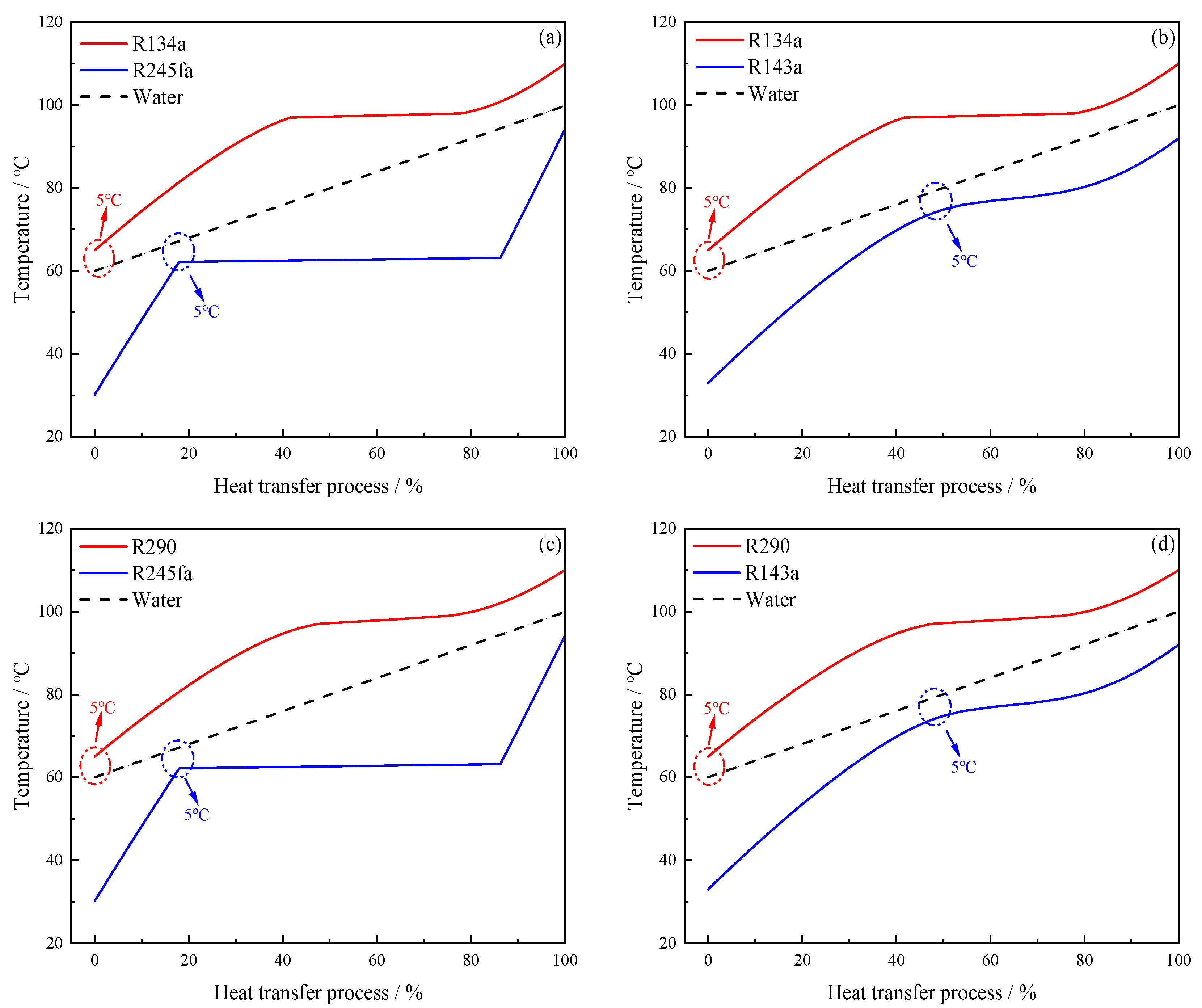
In Carnot batteries, the thermal storage loop directly affects system performance. In this regard, heat exchanges between fluids and pressurized water in the HP and ORC are illustrated in Figure 5. It can be observed that the pinch point between the HP fluid and the pressurized water consistently occurs at the inlet of Condenser1 (Cooler1). Additionally, when the ORC is in a subcritical state, the presence of latent heat results in poorer temperature matching performance between the ORC fluid and the pressurized water. Conversely, when the ORC is in a transcritical state, the temperature difference between the ORC fluid and the pressurized water is smaller. To sum up, SHP-TORC and THP-TORC exhibit better temperature matching performance.
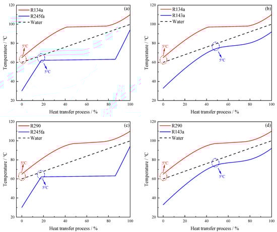
Figure 5.
Heat exchange between fluids and pressurized water for the four batteries: (a) SHP-SORC; (b) SHP-TORC; (c) THP-SORC; (d) THP-TORC.
Figure 6 details the calculated parameters for each point of the four batteries after identifying the working fluid combinations. In addition, Table 13 lists the key parameters for the charging and discharging processes of the four batteries. From the calculation results shown below, it can be seen that in the charging process, the four batteries absorb the same amount of heat from the DC, and the Compressor outlet temperature is also assumed to be the same. As a result, the heat absorption of pressurized water and the electricity consumption of the Compressor in SHP-SORC and SHP-TORC is equal due to the same cycle state of the HP, as well as with THP-SORC and THP-TORC. In addition, since the pressure of a subcritical HP is smaller than that of a transcritical HP, the power consumption (21.21 kW) in THP-SORC and THP-TORC is greater than that (20.29 kW) in SHP-SORC and SHP-TORC. Similarly, in the discharging process, both SHP-TORC and THP-TORC have relatively large electricity generation because of the higher ORC pressure, corresponding to 17.72 kW and 17.81 kW, respectively. In the same way, SHP-SORC produces slightly less electricity than THP-SORC, namely 14.59 kW and 14.67 kW. Furthermore, it can also be concluded that the cycle state of the ORC has a greater impact on system performance. Through comprehensive analysis of the obtained results, SHP-TORC has the highest RTE (76.42%), followed by THP-TORC (73.48%), SHP-SORC (62.91%), and THP-TORC (60.49%).
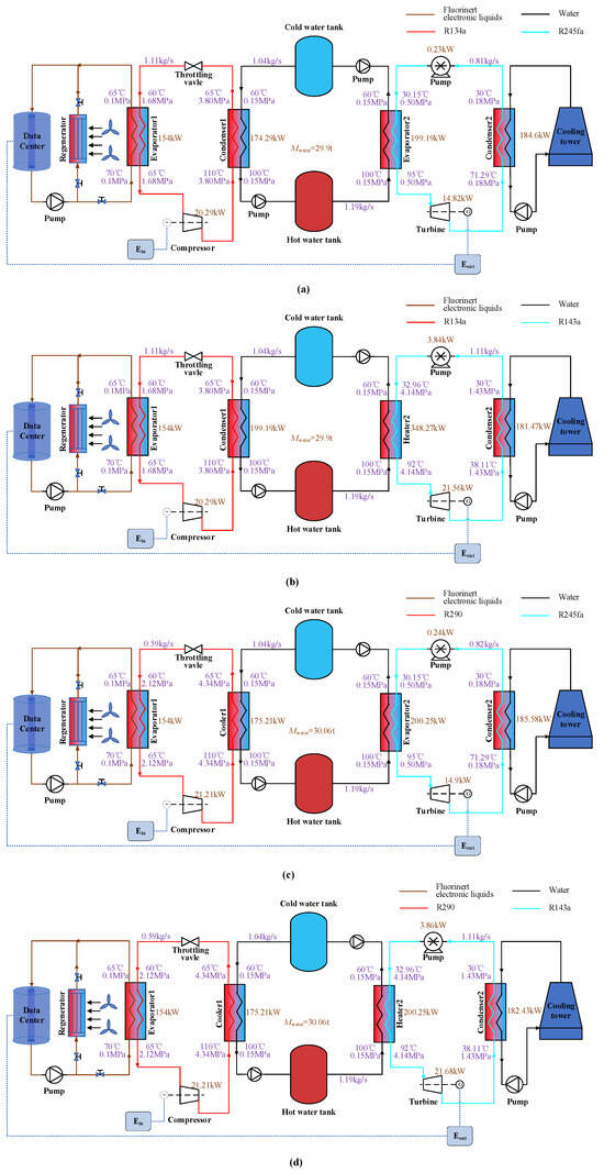
Figure 6.
State parameters of each point in the Carnot batteries: (a) SHP-SORC; (b) SHP-TORC; (c) THP-SORC; (d) THP-TORC.
Table 13.
Important parameters for the charging and discharging processes of the four batteries.
The exergy destruction of the main components is listed in Figure 7 for the four batteries. From Figure 7, it can be observed that the differences in exergy destruction of Evaporator1 are relatively insignificant from an overall standpoint. Similar observations apply to the Compressor. For Condenser1 in SHP-SORC and SHP-TORC, the evaporating temperature of the working fluid in a subcritical HP closely approaches its critical temperature. Consequently, the heat transfer temperature matching of Condenser1 in a subcritical HP is not markedly different from that of Cooler1 in a transcritical HP, as shown in Figure 5. Hence, the difference in exergy destruction in Condenser1 or Cooler1 among the four batteries is minimal. However, the exergy destruction of the Throttle valve in THP-SORC and THP-TORC is relatively high due to the higher pressure drop in the transcritical HP. Additionally, batteries with identical HP states present the same exergy destruction of components. Moreover, owing to the superior temperature matching of Heater2 in SHP-TORC and THP-TORC, the exergy destruction of Heater2 is much smaller than that of Evaporator2 in SHP-SORC and THP-SORC. Meanwhile, due to pressure effect in the ORC, the exergy destruction of the Turbine and Pump in SHP-TORC and THP-TORC is relatively high. Additionally, since the temperature difference of Condenser2 is larger in the subcritical ORC, the exergy destruction of Condenser2 is higher in SHP-SORC and THP-SORC. Similarly, in the same ORC state, the working fluid combination and design parameters are identical, thus resulting in little difference in their exergy destruction of components. Combining the above data, it can be concluded that THP-SORC has the highest total exergy destruction at 209.64 kW∙h, followed by SHP-SORC (203.21 kW∙h), THP-TORC (188.06 kW∙h), and SHP-TORC (181.75 kW∙h). However, exergy efficiency follows the reverse order.
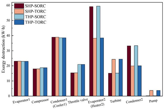
Figure 7.
Comparison of the exergy destruction of main components in the four Carnot batteries.
Table 14 unveils the economic performance across the four batteries. In SHP-SORC and THP-SORC, Evaporator1 constitutes the highest percentage of the total system cost, followed by Condenser1. In SHP-TORC and THP-TORC, Evaporator1 retains its status as the foremost component cost, trailed by the Turbine and Condenser1. Moreover, the total system costs of SHP-TORC and THP-TORC are comparatively high. This is because the costs of the Turbine and Pump are much higher when the ORC is in a transcritical state, which is caused by the higher pressure ratio. In addition, the lower Compressor cost in a transcritical HP makes THP-TORC less expensive than SHP-TORC. In terms of system cost, the obtained values for the four systems fall within the range reported in [18], confirming the consistency of the results with existing studies. Overall, SHP-SORC and SHP-TORC have higher system costs due to lower power generation, whereas THP-SORC and THP-TORC achieve lower system costs with higher power generation.
Table 14.
Economic performance comparison between the four Carnot batteries.
6.2. Effect of Evaporating Temperature in Evaporator1
For the four batteries, Figure 8 presents the variations of system performance with evaporating temperature. The temperature varies within 55–60 °C by considering the limitations of liquid cooling technology. As shown in Figure 8a, under a fixed Compressor outlet temperature, increasing the evaporating temperature reduces the HP temperature difference, thus enhancing the COP for the four batteries. Furthermore, a subcritical HP consistently outperforms a transcritical HP in COP due to lower power consumption. In addition, since the evaporating temperature only affects the operating parameters of the HP, ORC thermal efficiency remains constant under a fixed hot water temperature. Similarly, it can be seen that batteries in the transcritical ORC state have higher thermal efficiency.
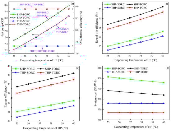
Figure 8.
Effects of the evaporating temperature of HPs on system performance: (a) COP and ORC thermal efficiency, (b) RTE, (c) exergy efficiency, (d) system cost.
Figure 8b illustrates the trend of RTE as a function of evaporating temperature. It can be observed that RTE shows an upward trend. This is mainly attributed to the decrease of Compressor power consumption. For the four batteries, the RTE variations are all similar, and SHP-TORC demonstrates the maximum RTE. On average, for every 1 °C increase in evaporating temperature, RTE increases by 1.84%. From Figure 8c, the trends for exergy efficiency are similar to those of RTE. The reduction of Compressor power consumption plays a dominant role in improving the exergy efficiency. On average, for every 1 °C increase, exergy efficiency increases by 0.24%.
Figure 8d demonstrates the effect of evaporating temperature on the system cost. As the evaporating temperature increases, system costs decline to varying degrees, primarily due to reduced Compressor costs. This reduction stems from lower Compressor power consumption at higher evaporating temperatures. Consequently, the total system cost decreases. Additionally, as power generation decreases with rising evaporating temperature, the system cost declines further due to simultaneous reductions in total cost and power output. On average, a 1 °C increase lowers system costs by 1.11 USD/kWh for SHP-SORC and SHP-TORC, and by 0.03 USD/kWh for THP-SORC and THP-TORC.
6.3. Effect of Temperature in Cold Water Tanks
To explore the impact of Cold water tank temperature, Figure 9 presents the variations of system performance in the temperature range of 60–65 °C. As shown in Figure 9a, with the temperature increases, COP shows a downward trend in overall terms. It can be explained by the fact that at a higher Cold water temperature, the Condenser1 (Cooler1) outlet temperature rises, thus increasing its outlet enthalpy. With the constant of Compressor power consumption at unit mass flow rate, COP decreases with the decrease of enthalpy difference between the inlet and outlet of Condenser1 (Cooler1). As for the ORC thermal efficiency, when the temperature change does not affect the parameters of each point in the ORC under the constraint of PPTDevap2, the thermal efficiency remains constant.
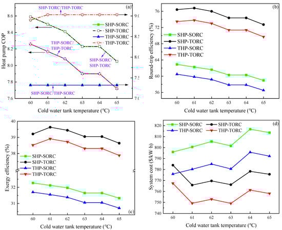
Figure 9.
Effects of the Cold water tank temperature on system performance: (a) COP and ORC thermal efficiency, (b) RTE, (c) exergy efficiency, (d) system cost.
From Figure 9b, it can be seen that the RTEs of all four batteries show a gradual declining trend, which can be explained by Equation (10). The RTE tends to decrease due to the faster growth rate of Compressor power consumption compared to net power output. On average, a 1 °C increase reduces RTE by 0.74%. From Figure 9c, consistent with the RTE analysis, under the joint influence of several parameters above, the exergy efficiencies of SHP-SORC and THP-SORC show a gradually decreasing trend, decreasing by an average of 0.20% at a temperature increase of 1 °C. Meanwhile, the exergy efficiencies of SHP-TORC and THP-TORC first increase then decrease, decreasing by an average of 0.19% at a temperature increase of 1 °C.
Figure 9d shows the relationship between Cold water tank temperature and system cost variations. For SHP-SORC and THP-SORC, system costs increase overall, rising by 4.15 USD/kWh per 1 °C increase. In contrast, SHP-TORC and THP-TORC initially see a decline before increasing, with an average rise of 3.55 USD/kWh per 1 °C increase.
6.4. Effects of Evaporating Temperature in Evaporator2
A key variable that affects the ORC thermal efficiency is the evaporating temperature, which is closely related to the high pressure in the ORC. Therefore, this section explores the impact of evaporating temperature on system performance. Since only the ORCs of SHP-SORC and THP-SORC are subcritical, only these two batteries are considered here.
By analyzing the data results shown in Figure 10a, it is evident that changing the evaporating temperature has no impact on the HP. For ORC thermal efficiency, a higher evaporating temperature leads to an increased pressure ratio in the ORC under the same heat absorption of the ORC fluid. As a result, both the value and upward trend of ORC thermal efficiency in the two batteries are the same within the temperature range.
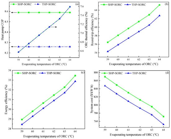
Figure 10.
Effects of evaporating temperature of ORC on system performance: (a) COP and ORC thermal efficiency, (b) RTE, (c) exergy efficiency, (d) system cost.
Since increasing the evaporating temperature has no effect on the power consumption of the HP, and results in an increase in power generation of the ORC, the RTE increases, as shown in Figure 10b. On average, when the temperature increases by 1 °C, the RTE increases by 1.75%. From Figure 10c, being similar to the previous analysis, with the increase of temperature, the exergy efficiencies of the two batteries increase. For every 1 °C increase in evaporating temperature, the exergy efficiencies of two batteries increase by 0.90%.
For the system cost, the increase in the ORC pressure ratio leads to a varying increase in the costs of the Turbine, Pump, and Condenser2. Under the combined effect of increasing ORC power generation and total system cost, the system cost decreases with the increase of evaporating temperature, as seen in Figure 10d. For every 1 °C increase in evaporating temperature, the system cost decreases by an average of 19.62 USD/kWh.
6.5. Effects of Outlet Temperature in Condenser2
The Condenser2 outlet temperature has a considerable impact on ORC thermal efficiency, thereby affecting the overall system performance. In addition, it is also highly correlated with the ambient temperature. As a result, in the temperature range of 14–30 °C, this section analyzes the impact of altering the Condenser2 outlet temperature on system performance.
Figure 11a shows the curves of COP and ORC thermal efficiency caused by the variation of Condenser2 outlet temperature. The COP remains unchanged in all four batteries, consistent with the previous analysis. For ORC thermal efficiency, being similar to the analysis in Section 6.4, when the Condenser2 outlet temperature increases, the thermal efficiencies for all four batteries gradually decrease.
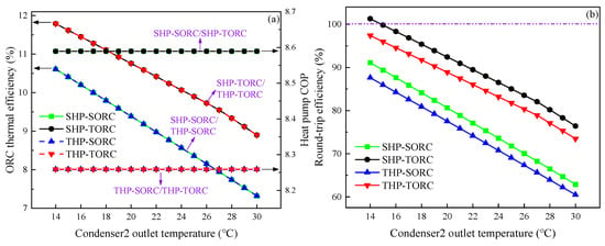
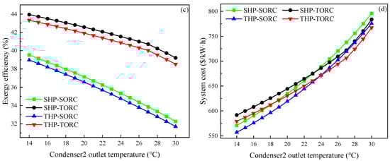
Figure 11.
Effects of the Condenser2 outlet temperature on system performance: (a) COP and ORC thermal efficiency, (b) RTE, (c) exergy efficiency, (d) system cost.
Figure 11b,c demonstrate the effects of Condenser2 outlet temperature on RTE and exergy efficiency, respectively. In the four batteries, due to the fact that the Compressor power consumption does not change, the RTEs all decrease gradually with a decrease in net power output. On average, the RTE decreases by an average of 1.66% for every 1 °C increase in temperature. Furthermore, it can be observed that when the Condenser2 outlet temperature is 14 °C, the RTE of SHP-TORC can reach 101.30%. This means that the electricity consumed by the HP can be completely offset by the electricity output from the ORC in cold regions. However, the RTE of SHP-TORC is as low as 76.42% when the temperature rises to 30 °C. As a result, the Carnot batteries have advantages in cold regions.
For the exergy efficiency, considering the fact that there is a positive correlation between the ambient temperature and the Condenser2 outlet temperature, and the ambient temperature tends to correlate negatively with the input exergy, so the input exergy decreases with the increase of Condenser2 outlet temperature. In addition, the Turbine power output also decreases with the temperature increase. Under this comprehensive influence, the values of all four batteries exhibit a declining trend. Overall, in SHP-SORC and THP-SORC, for every 1 °C increase in temperature, the exergy efficiencies decrease by an average of 0.45%. In SHP-TORC and THP-TORC, for every 1 °C increase in temperature, the exergy efficiencies decrease by an average of 0.30%.
In SHP-SORC and THP-SORC, the significant reduction in Turbine costs results in a progressive decrease in total system cost. However, the decrease is smaller in SHP-TORC and THP-TORC compared to SHP-SORC and THP-SORC, due to the combined effects of increased Condenser2 costs and reduced Turbine costs. Consequently, system costs in SHP-SORC and THP-SORC increase faster than in SHP-TORC and THP-TORC. As shown in Figure 11d, on average, for SHP-SORC and THP-SORC, a 1 °C increase results in a 14.08 USD/kWh increase, while for SHP-TORC and THP-TORC, the increase is 12.02 USD/kWh.
6.6. Optimization Performance Comparison of the Four Batteries
In this section, performance of the four HP-ORC Carnot batteries is optimized. The Compressor outlet temperature is varied to minimize the power consumption in the HP, and the Evaporator2 outlet temperature is iterated to maximize the net power output in the ORC, so as to get the maximal RTE.
Table 15 presents the optimized performance of the four batteries. For SHP-SORC and THP-SORC, since the temperatures of the Hot water tank and Compressor outlet can be as small as possible in a transcritical ORC on the basis of complying with the constraint of PPTD for each heat exchanger, the COPs rises by a large amount. However, due to the decrease in Evaporator2 outlet temperature, the ORC thermal efficiencies slightly decrease. Even so, there has been a significant improvement in the RTEs and the exergy efficiencies. As a comparison, for SHP-TORC and THP-TORC, as their ORCs are transcritical cycles, the Hot water tank temperature cannot be too low to allow liquid to enter the Turbine and cause damage to the Turbine. For this reason, the temperatures of the Compressor outlet and Hot water tank have little change compared with the corresponding values under the design conditions; thus, the optimized batteries have relatively small rise in both RTEs and exergy efficiencies. Moreover, it can be seen that after optimization, the RTE of SHP-SORC is the highest (82.68%), which is due to the fact that the system has minimum electricity consumption and therefore maximum RTE, even if it generates relatively low electricity. Additionally, the total exergy destruction of the optimized systems is reduced for the four batteries. Thus, the exergy efficiency is slightly increased. Meanwhile, being similar to the analysis under the design conditions, the exergy efficiencies of SHP-SORC and THP-SORC are lower, due to the worse temperature matching of heat exchangers.
Table 15.
Optimized performance comparison of the four Carnot batteries.
Table 16 demonstrates the comparison of the costs for the four batteries under design and optimized conditions. The data reveal a more substantial increase in total system costs for SHP-SORC and THP-SORC. This is primarily attributed to a significant decrease in the temperature difference between the Hot and Cold water tanks after optimization, which leads to an increase in the volume of the tanks, resulting in a drastic increase in the cost of the tanks, while in SHP-TORC and THP-TORC, the parameters of the systems at each point do not change significantly after optimization, resulting in only a slight investment cost change. Additionally, SHP-SORC and THP-SORC experience a significant increase in total power generation after optimization, leading to a significant rise in system costs, while SHP-TORC and THP-TORC see a slight reduction in costs due to a modest increase in power generation. Furthermore, it is noteworthy that despite SHP-SORC exhibiting the highest RTE, it also carries the larger total system cost.
Table 16.
Cost comparison for the four batteries under design and optimized conditions.
7. Conclusions
To assess the feasibility of integrating a Carnot battery in liquid-cooled DCs, this paper proposed four HP-ORC Carnot batteries driven by liquid-cooled DC waste heat, based on different combinations of HPs and ORCs. To obtain the performance of these batteries, thermo-economic models were developed. On this basis, the preferred working fluid combinations were determined for each battery. Thereafter, the effects of key parameters on system performance were discussed. Finally, the operating parameters of the different batteries were optimized with the objective of RTE. The main conclusions drawn are as follows:
- (1)
- Under the design conditions, R134a and R290 are identified as the optimum selections for the subcritical and transcritical HPs, while R245a and R143a are identified as the optimum selections for subcritical and transcritical ORCs, respectively. Systems operating in the transcritical ORC state exhibit better performance. SHP-TORC achieves the highest RTE of 76% and the highest exergy efficiency of 39%. Moreover, under a Condenser2 outlet temperature of 14 °C, the RTE of SHP-TORC can exceed 100%.
- (2)
- For the effects of operating parameters, the HP evaporating temperature has the greatest effect on RTE, with a mean value of 1.8%/°C. Additionally, the ORC evaporating temperature has the highest sensitivity to exergy efficiency. The exergy efficiency increases by 0.9% for every 1 °C increase in temperature. Moreover, the system cost varies greatly when the ORC evaporating temperature changes, and the temperature is negatively correlated with the system cost.
- (3)
- After optimization, when the Condenser2 outlet temperature is 30 °C, the RTE of SHP-SORC is the highest, reaching 83%. However, this improvement is accompanied by a significant increase in system cost, which rises to 1125 USD/kW∙h, an increase of 328 USD/kW∙h.
In this paper, only the RTE is considered in the optimization of the Carnot battery, and the system cost is not further optimized. However, system cost is a pivotal parameter in practical engineering applications. In general, systems with higher power output tend to achieve lower system costs, while the relatively higher system cost in this study is mainly attributed to the lower power generation. Therefore, future research should focus on multi-objective optimization that integrates both thermodynamic and economic performance of the system.
Besides the theoretical research, the practical application of HP-ORC Carnot batteries coupled with DCs still faces the following challenges: First, integrating the Carnot battery into existing data centers introduces spatial constraints and may require modifications to the cooling infrastructure, affecting overall system design and operation. Second, the use of fluorinated coolants, such as Fluorinert, raises environmental concerns due to the presence of PFAS (poly- and perfluorinated alkyl substances), which have been identified as persistent environmental pollutants. Third, operational challenges remain, including the management of charging and discharging cycles, dynamic control strategies, and real-time monitoring. Addressing these challenges will be essential for the real-world deployment of Carnot battery systems in DCs.
Author Contributions
Investigation, X.Z.; Methodology, X.L.; Software, X.Z. and W.S.; Supervision, Y.L.; Validation, R.D.; Writing—original draft, X.Z.; Writing—review and editing, W.S. All authors have read and agreed to the published version of the manuscript.
Funding
This work is sponsored by the Key R&D project of Hunan Province (2023GK2047). In addition, the work is also supported by the Central South University Innovation-Driven Research Program (2023CXQD056) and Graduate Research Innovation Project of Central South University (1053320231410).
Data Availability Statement
The original contributions presented in this study are included in the article. Further inquiries can be directed to the corresponding author.
Conflicts of Interest
Authors Xinxing Lin and Ruochen Ding were employed by the company China Three Gorges Corporation. The remaining authors declare that the research was conducted in the absence of any commercial or financial relationships that could be construed as a potential conflict of interest.
Nomenclature
| C | Cost, USD |
| A | Heat exchange areas, m3 |
| Specific exergy, J/kg | |
| Specific enthalpy, J/kg | |
| H | Head of Water pump, m |
| I | Exergy destruction, kW∙h |
| k | Discount rate, % |
| Mass flow rate, kg/s | |
| Total mass, kg | |
| Pressure, MPa | |
| Heat transfer rate, W | |
| Specific entropy, J/(kg∙K) | |
| Time, h | |
| Temperature, °C | |
| V | Volume, m3 |
| Work, W | |
| Greek symbols | |
| ηexergy | Exergy efficiency, % |
| ηis,com | Isentropic efficiency of the Compressor, % |
| ηis,p | Isentropic efficiency of the Pump, % |
| ηis,tur | Isentropic efficiency of the Turbine, % |
| ηORC | ORC thermal efficiency, % |
| ηwp1 | Efficiency of the Water pump1, % |
| ηwp2 | Efficiency of the Water pump2, % |
| Abbreviations | |
| CEPCI | Chemical Engineering Plant Cost Index |
| COP | Coefficient of performance |
| DC | Data center |
| RTE | Round-trip efficiency |
| HP | Heat pump |
| ORC | Organic Rankine cycle |
| PPTD | Pinch point temperature difference |
| SHP | Subcritical heat pump |
| SORC | Subcritical organic Rankine cycle |
| THP | Transcritical heat pump |
| tk | Tank |
| TORC | Transcritical organic Rankine cycle |
| Subscript | |
| 0 | Ambient |
| 1,2,3…i | Thermodynamic state points |
| ave | Average |
| C | Cold-side working fluid |
| c1 | Cooler1 |
| charge | The charging process |
| com | Compressor |
| cond1 | Condenser1 |
| cond2 | Condenser2 |
| conting | Contingency |
| discharge | The discharging process |
| eng | Engineering |
| evap1 | Evaporator1 |
| evap2 | Evaporator2 |
| f1 | Heat pump working fluid |
| f2 | Organic Rankine cycle working fluid |
| h | High temperature |
| H | Hot-side working fluid |
| h2 | Heater2 |
| in | Inlet |
| instal | Installation |
| invest | Investment |
| l | Low temperature |
| out | Outlet |
| sup | Superheat |
| tot | Total |
| tow | Cooling tower |
| tur | Turbine |
| w1 | Pressurized water during charging process |
| w2 | Pressurized water during discharging process |
References
- China Computational Power Platform. China Computing Power Development Report 2024. Available online: https://www.cpz.org.cn/news/720071589999399213.html (accessed on 12 January 2025).
- Hao, Y.T.; Zhou, H.J.; Tian, T.; Zhang, W.; Zhou, X.; Shen, Q.F.; Wu, T.; Li, J. Data centers waste heat recovery technologies: Review and evaluation. Appl. Energy 2025, 384, 125489. [Google Scholar]
- Chu, J.J.; Huang, X. Research status and development trends of evaporative cooling air-conditioning technology in data centers. Energy Built Environ. 2023, 4, 86–110. [Google Scholar]
- Liang, Y.R.; Lin, X.X.; Su, W.; Xing, L.L.; Wan, L.; Wang, B. Preliminary design and optimization of a solar-driven combined cooling and power system for a data center. Energy Convers. Manag. X 2023, 20, 100409. [Google Scholar]
- Zhang, C.Q.; Luo, H.X.; Wang, Z.X. An economic analysis of waste heat recovery and utilization in data centers considering environmental benefits. Sustain. Prod. Consum. 2022, 31, 127–138. [Google Scholar]
- Hnayno, M.; Chehade, A.; Klaba, H.; Polidori, G.; Maalouf, C. Experimental investigation of a data-centre cooling system using a new single-phase immersion/liquid technique. Case Stud. Therm. Eng. 2023, 45, 102925. [Google Scholar]
- Ebrahimi, K.; Jones, G.F.; Fleischer, A.S. A review of data center cooling technology, operating conditions and the corresponding low-grade waste heat recovery opportunities. Renew. Sustain. Energy Rev. 2014, 31, 622–638. [Google Scholar]
- Huang, P.; Copertaro, B.; Zhang, X.X.; Shen, J.C.; Lofgren, I.; Ronnelid, M.; Fahlen, J.; Andersson, D.; Svanfeldt, M. A review of data centers as prosumers in district energy systems: Renewable energy integration and waste heat reuse for district heating. Appl. Energy 2020, 258, 114109. [Google Scholar]
- Lu, T.; Lu, X.S.; Remes, M.; Viljanen, M. Investigation of air management and energy performance in a data center in Finland: Case study. Energy Build. 2011, 43, 3360–3372. [Google Scholar]
- Davies, G.F.; Maidment, G.G.; Tozer, R.M. Using data centres for combined heating and cooling: An investigation for London. Appl. Therm. Eng. 2016, 94, 296–304. [Google Scholar]
- Chen, X.T.; Pan, M.Z.; Li, X.Y.; Zhang, K. Multi-mode operation and thermo-economic analyses of combined cooling and power systems for recovering waste heat from data centers. Energy Convers. Manag. 2022, 266, 115820. [Google Scholar]
- Ebrahimi, K.; Jones, G.F.; Fleischer, A.S. The viability of ultra low temperature waste heat recovery using organic Rankine cycle in dual loop data center applications. Appl. Therm. Eng. 2017, 126, 393–406. [Google Scholar]
- Marshall, Z.M.; Duquette, J. A techno-economic evaluation of low global warming potential heat pump assisted organic Rankine cycle systems for data center waste heat recovery. Energy 2022, 242, 122528. [Google Scholar]
- Li, F.H.; Xing, L.L.; Su, W.; Lin, X.X.; Liang, Y.R.; Shi, W.J. An idea to construct integrated energy systems of data center by combining CO2 heat pump and compressed CO2 energy storage. J. Energy Storage 2024, 75, 109581. [Google Scholar]
- Zhou, Y.; Hao, W.H. Research on Application of Energy Storage System for Data Center. South. Energy Constr. 2021, 8, 58–62. [Google Scholar]
- Li, X.H.; Pang, A.P.; Yang, W.; Zhao, Q.C. VRLA battery fault prediction for data center based on random forest model and feature enhancement method. J. Energy Storage 2023, 72, 108666. [Google Scholar]
- Liang, Y.R.; Li, P.; Xing, L.L.; Su, W.; Li, W.; Xu, W. Current status of thermodynamic electricity storage: Principle, structure, storage device and demonstration. J. Energy Storage 2024, 80, 110347. [Google Scholar]
- Mercangoez, M.; Hemrle, J.; Kaufmann, L.; Z’Graggen, A.; Ohler, C. Electrothermal energy storage with transcritical CO2 cycles. Energy 2012, 45, 407–415. [Google Scholar] [CrossRef]
- Benato, A.; Stoppato, A. Pumped Thermal Electricity Storage: A technology overview. Therm. Sci. Eng. Prog. 2018, 6, 301–315. [Google Scholar]
- Dumont, O.; Frate, G.F.; Pillai, A.; Lecompte, S.; De Paepe, M.; Lemort, V. Carnot battery technology: A state-of-the-art review. J. Energy Storage 2020, 32, 101756. [Google Scholar] [CrossRef]
- Frate, G.F.; Ferrari, L.; Desideri, U. Multi-Criteria Economic Analysis of a Pumped Thermal Electricity Storage (PTES) with Thermal Integration. Front. Energy Res. 2020, 8, 53. [Google Scholar] [CrossRef]
- Yu, X.H.; Qiao, H.N.; Yang, B.; Zhang, H.T. Thermal-economic and sensitivity analysis of different Rankine-based Carnot battery configurations for energy storage. Energy Convers. Manag. 2023, 283, 116959. [Google Scholar] [CrossRef]
- Steger, D.; Regensburger, C.; Eppinger, B.; Will, S.; Karl, J.; Schluecker, E. Design aspects of a reversible heat pump—Organic rankine cycle pilot plant for energy storage. Energy 2020, 208, 118216. [Google Scholar] [CrossRef]
- Scharrer, D.; Bazan, P.; Pruckner, M.; German, R. Simulation and analysis of a Carnot Battery consisting of a reversible heat pump/organic Rankine cycle for a domestic application in a community with varying number of houses. Energy 2022, 261, 125166. [Google Scholar] [CrossRef]
- Staub, S.; Bazan, P.; Braimakis, K.; Mueller, D.; Regensburger, C.; Scharrer, D.; Schmitt, B.; Steger, D.; German, R.; Karellas, S.; et al. Reversible Heat Pump-Organic Rankine Cycle Systems for the Storage of Renewable Electricity. Energies 2018, 11, 1352. [Google Scholar] [CrossRef]
- Dumont, O.; Reyes, A.; Lemort, V. Modelling of a thermally integrated Carnot battery using a reversible heat pump/organic Rankine cycle. In Proceedings of the 33rd International Conference on Efficiency, Cost, Optimization, Simulation and Environmental Impact of Energy Systems, Osaka, Japan, 29 June–3 July 2020. [Google Scholar]
- Frate, G.F.; Ferrari, L.; Desideri, U. Multi-criteria investigation of a pumped thermal electricity storage (PTES) system with thermal integration and sensible heat storage. Energy Convers. Manag. 2020, 208, 112530. [Google Scholar] [CrossRef]
- Niu, J.T.; Wang, J.S.; Liu, X.L.; Dong, L.W. Optimal integration of solar collectors to Carnot battery system with regenerators. Energy Convers. Manag. 2023, 277, 116625. [Google Scholar] [CrossRef]
- Yaïci, W.; Entchev, E.; Longo, M. Organic Rankine cycle-ejector heat pump hybrid system using low GWP zeotropic mixtures for trigeneration application. Energy Convers. Manag. 2024, 299, 117853. [Google Scholar] [CrossRef]
- Liang, Y.R.; Li, P.; Su, W.; Li, W.; Xu, W. Development of green data center by configuring photovoltaic power generation and compressed air energy storage systems. Energy 2024, 292, 130516. [Google Scholar] [CrossRef]
- Hamdy, S.; Morosuk, T.; Tsatsaronis, G. Exergetic and economic assessment of integrated cryogenic energy storage systems. Cryogenics 2019, 99, 39–50. [Google Scholar] [CrossRef]
- Benato, A. Performance and cost evaluation of an innovative Pumped Thermal Electricity Storage power system. Energy 2017, 138, 419–436. [Google Scholar] [CrossRef]
- Gutierrez, J.C.; Ochoa, G.V.; Duarte-Forero, J. A comparative study of the energy, exergetic and thermo-economic performance of a novelty combined Brayton S-CO2-ORC configurations as bottoming cycles. Heliyon 2020, 6, e04459. [Google Scholar]
- Liang, T.; Vecchi, A.; Knobloch, K.; Sciacovelli, A.; Engelbrecht, K.; Li, Y.L.; Ding, Y.L. Key components for Carnot Battery: Technology review, technical barriers and selection criteria. Renew. Sustain. Energy Rev. 2022, 163, 112478. [Google Scholar]
- Carotenuto, A.; Figaj, R.; Vanoli, L. A novel solar-geothermal district heating, cooling and domestic hot water system: Dynamic simulation and energy-economic analysis. Energy 2017, 141, 2652–2669. [Google Scholar]
- Hu, S.Z.; Yang, Z.; Li, J.; Duan, Y.Y. Thermo-economic analysis of the pumped thermal energy storage with thermal integration in different application scenarios. Energy Convers. Manag. 2021, 236, 114072. [Google Scholar] [CrossRef]
- Coker, A. Ludwig’s Applied Process Design for Chemical and Petrochemical Plants; Gulf Professional Publishing: Woburn, MA, USA, 2014. [Google Scholar]
- Vieira, L.S.; Donatelli, J.L.; Cruz, M.E. Exergoeconomic improvement of a complex cogeneration system integrated with a professional process simulator. Energy Convers. Manag. 2009, 50, 1955–1967. [Google Scholar]
- Mignard, D. Correlating the chemical engineering plant cost index with macro-economic indicators. Chem. Eng. Res. Des. 2014, 92, 285–294. [Google Scholar]
- Zhang, X.; Sun, Y.; Zhao, W.L.; Li, C.; Xu, C.; Sun, H.C.; Yang, Q.R.; Tian, X.L.; Wang, D.C. The Carnot batteries thermally assisted by the steam extracted from thermal power plants: A thermodynamic analysis and performance evaluation. Energy Convers. Manag. 2023, 297, 117724. [Google Scholar] [CrossRef]
- Kondou, C.; Koyama, S. Thermodynamic assessment of high-temperature heat pumps using Low-GWP HFO refrigerants for heat recovery. Int. J. Refrig. 2015, 53, 126–141. [Google Scholar]
- Chen, C.H.; Ou, S.D.; Su, W.; Li, X.Y.; Lin, X.X.; Zhou, N.J. Recent advances on transcritical power cycles based on organic fluids and CO2. Clean Coal Technol. 2022, 28, 125–142. [Google Scholar]


Disclaimer/Publisher’s Note: The statements, opinions and data contained in all publications are solely those of the individual author(s) and contributor(s) and not of MDPI and/or the editor(s). MDPI and/or the editor(s) disclaim responsibility for any injury to people or property resulting from any ideas, methods, instructions or products referred to in the content. |
© 2025 by the authors. Licensee MDPI, Basel, Switzerland. This article is an open access article distributed under the terms and conditions of the Creative Commons Attribution (CC BY) license (https://creativecommons.org/licenses/by/4.0/).