
Performance Evaluation of Pressure Swing Adsorption for Hydrogen Separation from Syngas and Water–Gas Shift Syngas

 , , , and
Abstract
:1. Introduction
2. Review of Hydrogen Separation Technologies
- Feed preparation;
- Reactions;
- Purification.
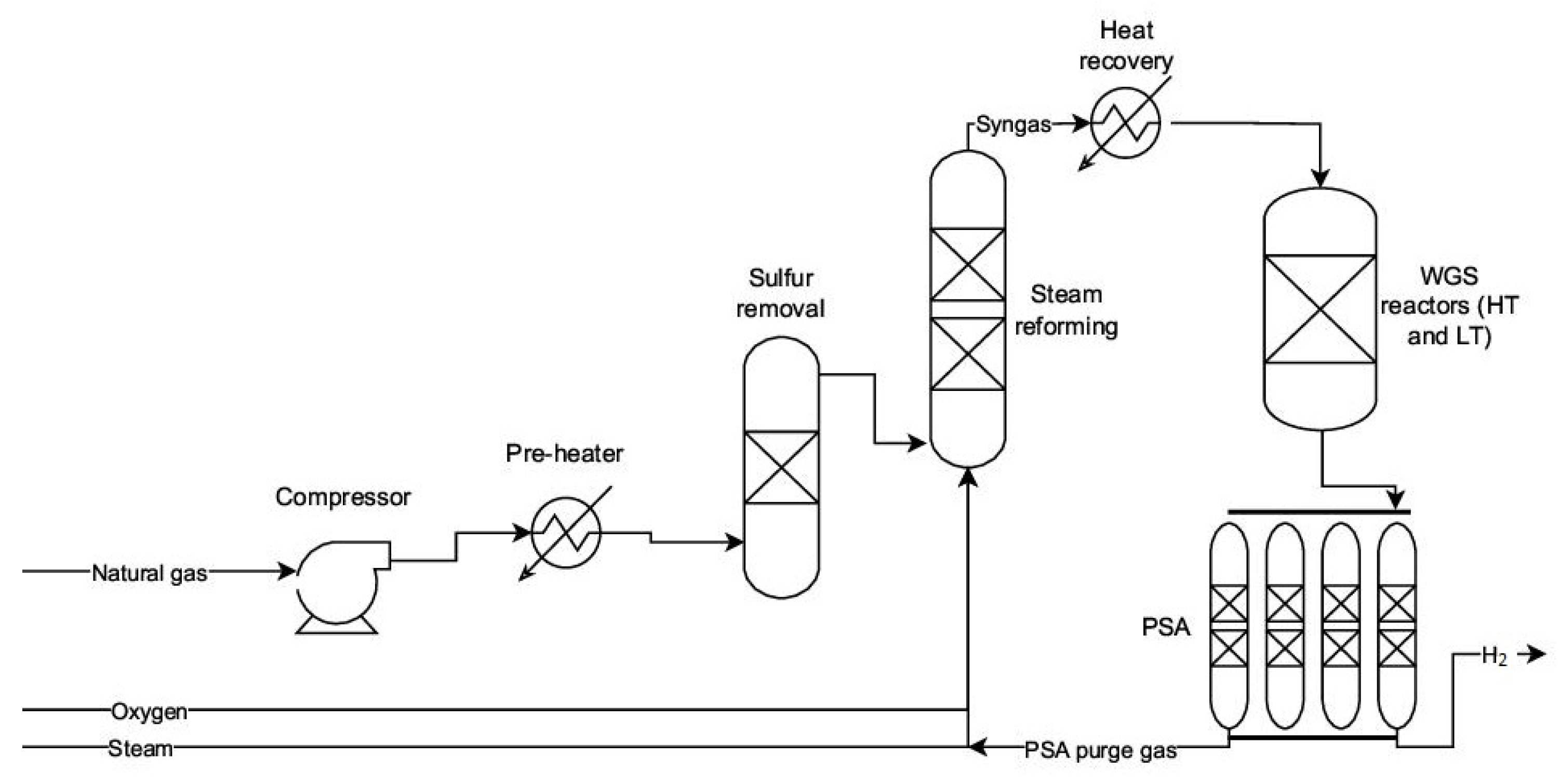
2.1. Syngas Production Methods: Gasification, Reforming, Oxidation
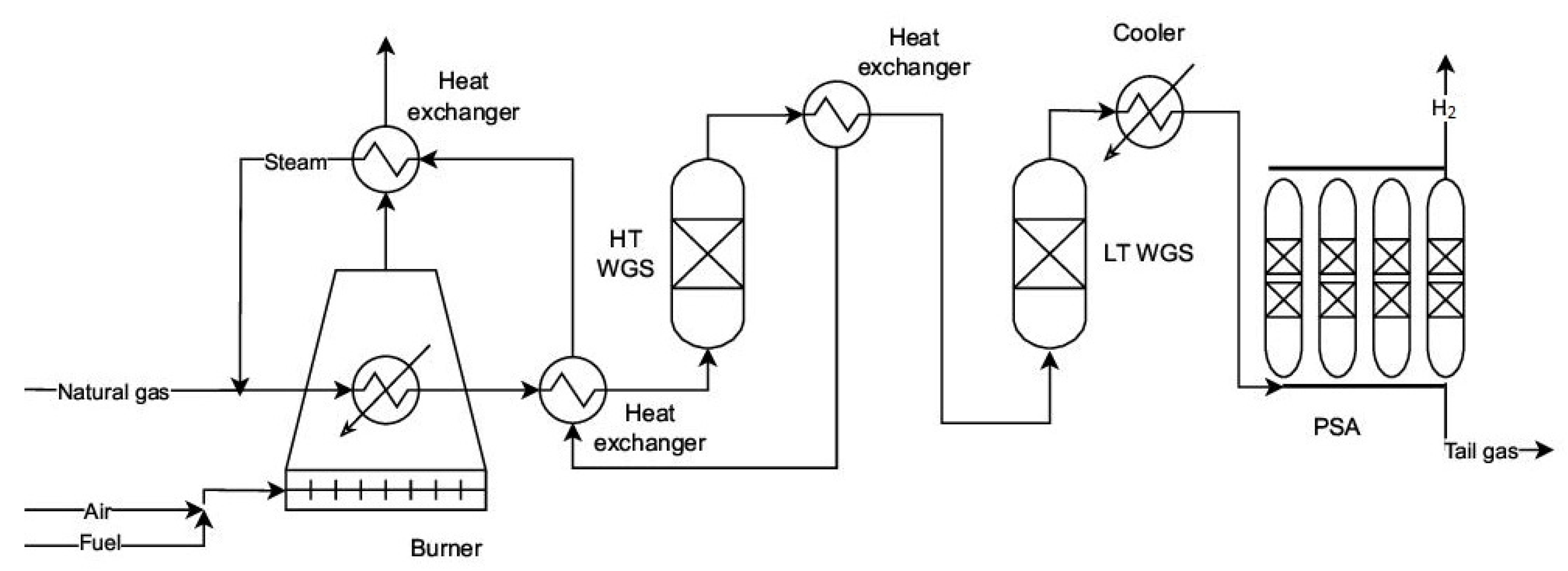
2.2. WGS Reaction and Its Role in Hydrogen Enrichment
2.3. Hydrogen Purity Requirements for Different Applications
3. PSA Fundamentals and Key Process Variables
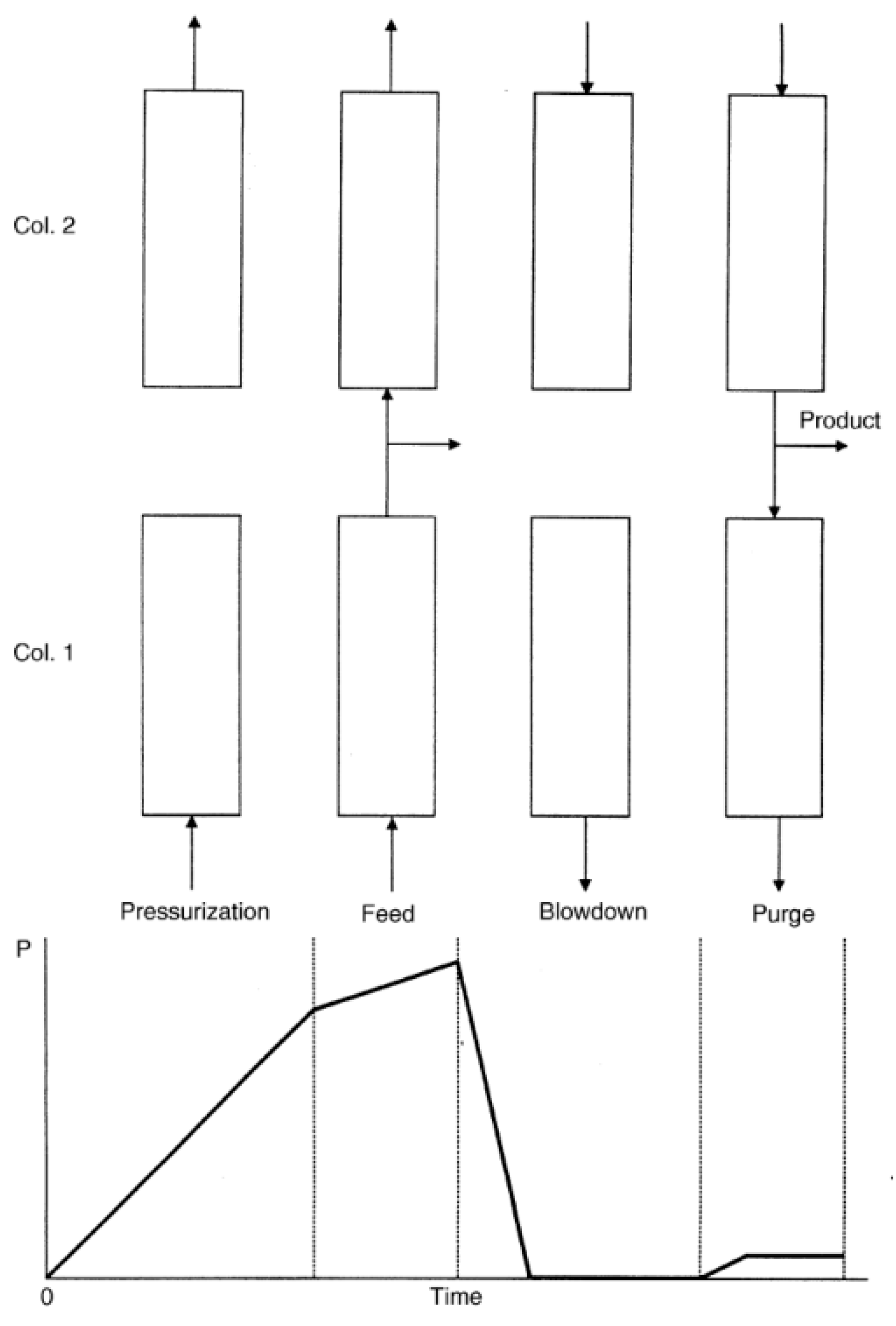
3.1. PSA Process Concepts (Cycle Sequences)
- A.
- Adsorption
- B.
- Desorption
- Pressure equalization 2: The pressure reduction begins in the co-current direction relative to the previous gas flow (from bottom to top). The raffinate remaining in the empty space of the adsorbent is used to increase the pressure in another adsorber that has just completed regeneration. Depending on the total number of adsorbers and process conditions, one to four pressure equalization steps are performed. Each additional pressure equalization step minimizes raffinate losses.
- Provide purge: Once the pressure is equalized, part of the gas contained in the column under pressure is used to provide flushing for another column.
- Blowdown: This is the final stage of pressure reduction. The gas from the column undergoing pressure reduction provides the raffinate stream for regenerating another adsorber.
- Purge: Final desorption and regeneration occur at the lowest pressure of the PSA sequence (cycle). Highly pure raffinate, obtained from the adsorber during the purification stage, is used to remove adsorbed contaminants into the off-gas (extract) system.
- Pressure equalization 1: Before resuming adsorption, the regenerated adsorber must be refilled to high pressure. This is achieved during the pressure equalization step using raffinate from adsorbers currently at reduced pressure.
- Compression with the product: Since the final adsorption pressure cannot be reached through pressure equalization alone, the pressure is further increased to the adsorption pressure using a separated stream from the product line. This ensures that, during the adsorption phase, high raffinate purity is consistently maintained.
3.2. PSA Adsorbents Rewiew
- Adsorption capacity and selectivity for syngas impurities;
- Suitable kinetics for adsorption and desorption;
- Adequate adsorption and mechanical stability through multiple regeneration cycles;
3.3. Key Operational Parameters Affecting PSA Performance
4. Design of Experiments for PSA-Based Hydrogen Separation
- A 1:1 volume ratio, corresponding to 60 cm of activated carbon and 60 cm of zeolite.
- A 1.6:1 volume ratio, corresponding to 75 cm of activated carbon and 45 cm of zeolite.
5. Expected Outcomes and Challenges
5.1. Adsorption Behaviors and Breakthrough Curves
5.2. Hydrogen Purity and Recovery in PSA Experiments
5.3. Challenges and Future Research Directions
6. Discussion and Conclusions
Author Contributions
Funding
Data Availability Statement
Conflicts of Interest
Abbreviations
| AC | Activated Carbon |
| AG2S™ | Acid Gas to Syngas process |
| ARM | Autothermal Reforming of Methane |
| BRM | Bi-Reforming of Methane |
| DRM | Dry Reforming of Methane |
| ET-PSA | Elevated Temperature Pressure Swing Adsorption |
| Extract | Low-pressure PSA Process End Gas |
| F–T | Fischer–Tropsh process |
| HT | High Temperature |
| ITPE | Institute of Energy and Fuel Processing Technology |
| MOF | Metal–Organic Frameworks |
| MTZ | Mass Transfer Zones |
| n | Standard Conditions (1.01 bar, 0 °C) |
| NT-PSA | Normal Temperature Pressure Swing Adsorption |
| p | Pressure |
| P/F | Purge-to-Feed Inlet Gas Ratio |
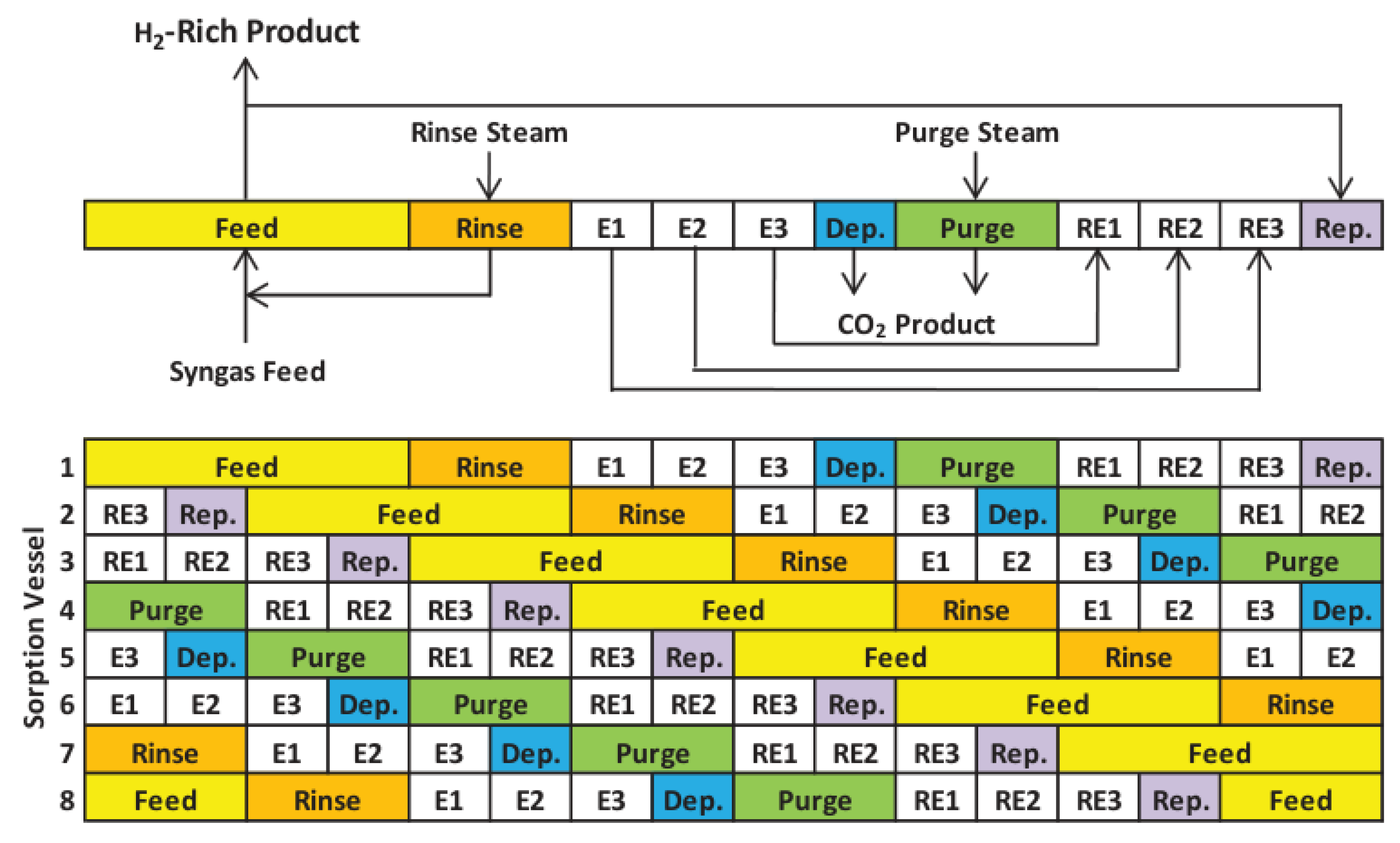
| SEWGS | Sorption-Enhanced Water–Gas Shift |
| SERP | Sorption Enhanced Reaction Process |
| Syngas | Synthetic Gas |
| STP | Standard Conditions (1.01 bar, 20 °C) |
| SRM | Steam Reforming of Methane |
| SMROG | Steam Methane Reformer Off Gas |
| Raffinate | High Pressure PSA Process End Gas |
| RPSA | Rapid Pressure Swing Adsorption |
| ROG | Refinery Off-Gas |
| POM | Partial Oxidation of Methane |
| PSA | Pressure Swing Adsorption |
| SCADA | Supervisory Control and Data Acquisition |
| WGS | Water–Gas Shift |
| WGSR | Water–Gas Shift Reaction |
| VPSA | Vacuum Pressure Swing Adsorption |
References
- Du, Z.; Liu, C.; Zhai, J.; Guo, X.; Xiong, Y.; Su, W.; He, G. A Review of Hydrogen Purification Technologies for Fuel Cell Vehicles. Catalysts 2021, 11, 393. [Google Scholar] [CrossRef]
- Budner, Z.; Reterska, Z.; Morawiec, B. Technologia Wydzielania Wodoru z Gazów Rafineryjnych Metodš PSA. Przem. Chem. 1989, 69, 533–534. [Google Scholar]
- Sircar, S.; Golden, T.C. Pressure Swing Adsorption Technology for Hydrogen Production. In Hydrogen and Syngas Production and Purification Technologies; John Wiley & Sons, Ltd.: Hoboken, NJ, USA, 2009; pp. 414–450. ISBN 978-0-470-56125-6. [Google Scholar]
- Douglas, M. Ruthven and All Pressure Swing Adsorption; WILEY-VCH: New York, NY, USA, 1994. [Google Scholar]
- Front Matter. In Gas Separation by Adsorption Processes; Yang, R.T., Ed.; Butterworth-Heinemann: Oxford, UK, 1987; p. iii. ISBN 978-0-409-90004-0. [Google Scholar]
- Song, Q. Development and Prospect of Pressure Swing Adsorption (PSA) Technology for Carbon Dioxide Separation and Capture. Int. J. Trend Res. Dev. 2024, 11, 19–24. [Google Scholar]
- Liu, J.; Wei, Y.; Li, P.; Zhao, Y.; Zou, R. Selective H2S/CO2 Separation by Metal–Organic Frameworks Based on Chemical-Physical Adsorption. J. Phys. Chem. C 2017, 121, 13249–13255. [Google Scholar] [CrossRef]
- Li, B.; He, G.; Jiang, X.; Dai, Y.; Ruan, X. Pressure Swing Adsorption/Membrane Hybrid Processes for Hydrogen Purification with a High Recovery. Front. Chem. Sci. Eng. 2016, 10, 255–264. [Google Scholar] [CrossRef]
- Król, A.; Gajec, M.; Holewa-Rataj, J.; Kukulska-Zając, E.; Rataj, M. Hydrogen Purification Technologies in the Context of Its Utilization. Energies 2024, 17, 3794. [Google Scholar] [CrossRef]
- H2GEO—New Technology for Hydrogen and Geopolymer Composites Production. Available online: https://h2geo.komag.eu/ (accessed on 18 February 2025).
- Comprehensive Public Overview of the Project. Available online: https://h2geo.komag.eu/wp-content/uploads/2023/12/H2GEO_The_comprehensive_public_overview_of_the_project_D_1_3.pdf (accessed on 18 February 2025).
- Rauch, R.; Kiros, Y.; Engvall, K.; Kantarelis, E.; Brito, P.; Nobre, C.; Santos, S.M.; Graefe, P.A. Hydrogen from Waste Gasification. Hydrogen 2024, 5, 70–101. [Google Scholar] [CrossRef]
- Eh Christina, L.M.; Tiong Angnes, N.T.; Kansedo, J.; Lim, C.H.; How, B.S.; Ng, W.P.Q. Circular Hydrogen Economy and Its Challenges. Chem. Eng. Trans. 2022, 94, 1273–1278. [Google Scholar] [CrossRef]
- Rostrup-Nielsen, J.R. New Aspects of Syngas Production and Use. Catal. Today 2000, 63, 159–164. [Google Scholar] [CrossRef]
- Aramouni, N.A.K.; Touma, J.G.; Tarboush, B.A.; Zeaiter, J.; Ahmad, M.N. Catalyst Design for Dry Reforming of Methane: Analysis Review. Renew. Sustain. Energy Rev. 2018, 82, 2570–2585. [Google Scholar] [CrossRef]
- Chong, C.C.; Bukhari, S.N.; Cheng, Y.W.; Setiabudi, H.D.; Jalil, A.A.; Phalakornkule, C. Robust Ni/Dendritic Fibrous SBA-15 (Ni/DFSBA-15) for Methane Dry Reforming: Effect of Ni Loadings. Appl. Catal. A Gen. 2019, 584, 117174. [Google Scholar] [CrossRef]
- Abdullah, B.; Abd Ghani, N.A.; Vo, D.-V.N. Recent Advances in Dry Reforming of Methane over Ni-Based Catalysts. J. Clean. Prod. 2017, 162, 170–185. [Google Scholar] [CrossRef]
- Singh Sikarwar, V.; Zhao, M.; Clough, P.; Yao, J.; Zhong, X.; Zaki Memon, M.; Shah, N.; Anthony, E.J.; Fennell, P.S. An Overview of Advances in Biomass Gasification. Energy Environ. Sci. 2016, 9, 2939–2977. [Google Scholar] [CrossRef]
- Silva, V.; Tuna, C.E.; Silva, V.; Tuna, C.E. Gasification; IntechOpen: Rijeka, Croatia, 2021; ISBN 978-1-83968-796-9. [Google Scholar]
- Speight, J.G. Synthesis Gas: Production and Properties; John Wiley & Sons: Hoboken, NJ, USA, 2020; ISBN 978-1-119-70772-1. [Google Scholar]
- Penã, M.A.; Gómez, J.P.; Fierro, J.L.G. New Catalytic Routes for Syngas and Hydrogen Production. Appl. Catal. A Gen. 1996, 144, 7–57. [Google Scholar] [CrossRef]
- Arman, A.; Hagos, F.Y.; Abdullah, A.A.; Mamat, R.; Aziz, A.R.A.; Cheng, C.K. Syngas Production through Steam and CO2 Reforming of Methane over Ni-Based Catalyst—A Review. IOP Conf. Ser. Mater. Sci. Eng. 2020, 736, 042032. [Google Scholar] [CrossRef]
- Jithin, E.V.; Raghuram, G.K.S.; Keshavamurthy, T.V.; Velamati, R.K.; Prathap, C.; Varghese, R.J. A Review on Fundamental Combustion Characteristics of Syngas Mixtures and Feasibility in Combustion Devices. Renew. Sustain. Energy Rev. 2021, 146, 111178. [Google Scholar] [CrossRef]
- Wibowo, H.; Susanto, H.; Grisdanurak, N.; Hantoko, D.; Yoshikawa, K.; Qun, H.; Yan, M. Recent Developments of Deep Eutectic Solvent as Absorbent for CO2 Removal from Syngas Produced from Gasification: Current Status, Challenges, and Further Research. J. Environ. Chem. Eng. 2021, 9, 105439. [Google Scholar] [CrossRef]
- Moon, D.-K.; Park, Y.; Oh, H.-T.; Kim, S.-H.; Oh, M.; Lee, C.-H. Performance Analysis of an Eight-Layered Bed PSA Process for H2 Recovery from IGCC with Pre-Combustion Carbon Capture. Energy Convers. Manag. 2018, 156, 202–214. [Google Scholar] [CrossRef]
- Primus, A.; Rosik-Dulewska, C. Produkcja Energii w Źródłach Kogeneracyjnych Małej Mocy z Wykorzystaniem Technologii Zgazowania Odpadów Pochodzenia Komunalnego. Uwarunkowania Prawne i Ekonomiczne. Polityka Energetyczna Energy Policy J. 2017, 20, 79–92. [Google Scholar]
- Zgazowanie Biomasy. Technologia. Witold Warowny Politechnika Warszawska. Wydział Budownictwa, Mechaniki i Petrochemii Ul. Łukasiewicza 17, PDF Darmowe Pobieranie. Available online: https://docplayer.pl/10525313-Zgazowanie-biomasy-technologia-witold-warowny-politechnika-warszawska-wydzial-budownictwa-mechaniki-i-petrochemii-ul-lukasiewicza-17-09-400.html (accessed on 24 January 2025).
- Mingaleeva, G.; Ermolaev, D.; Galkeeva, A. Physico-Chemical Foundations of Produced Syngas during Gasification Process of Various Hydrocarbon Fuels. Clean Technol. Environ. Policy 2016, 18, 297–304. [Google Scholar] [CrossRef]
- Gogate, M. Water-Gas Shift Reaction: Advances and Industrial Applications. Prog. Petrochem. Sci. 2020, 3. [Google Scholar] [CrossRef]
- Smith, B.; Muruganandam, L.; Murthy, L.; Shantha, S. A Review of the Water Gas Shift Reaction Kinetics. Int. J. Chem. React. Eng. 2010, 8. [Google Scholar] [CrossRef]
- Pasel, J.; Samsun, R.C.; Schmitt, D.; Peters, R.; Stolten, D. Test of a Water–Gas-Shift Reactor on a 3 kWe-Scale—Design Points for High- and Low-Temperature Shift Reaction. J. Power Sources 2005, 152, 189–195. [Google Scholar] [CrossRef]
- ISO 14687:2025. Available online: https://www.iso.org/standard/82660.html (accessed on 19 February 2025).
- Aarhaug, T.A.; Kjos, O.; Bacquart, T.; Valter, V.; Optenhostert, T. Assessment of Hydrogen Quality Dispensed for Hydrogen Refuelling Stations in Europe. Int. J. Hydrogen Energy 2021, 46, 29501–29511. [Google Scholar] [CrossRef]
- Kohl, A.L. Gas Purification, 5th ed.; Gulf Professional Publishing: Houston, TX, USA, 1997; ISBN 978-0-88415-220-0. [Google Scholar]
- Agrawal, R.; Herron, D.M. Optimal Thermodynamic Feed Conditions for Distillation of Ideal Binary Mixtures. AIChE J. 1997, 43, 2984–2996. [Google Scholar] [CrossRef]
- Siriwardane, R.V.; Shen, M.-S.; Fisher, E.P.; Losch, J. Adsorption of CO2 on Zeolites at Moderate Temperatures. Energy Fuels 2005, 19, 1153–1159. [Google Scholar] [CrossRef]
- Advances in Synthesis Gas: Methods, Technologies and Applications; Elsevier: Amsterdam, The Netherlands, 2022; ISBN 978-0-323-91877-0.
- Santos, M.G.R.S.; Correia, L.M.S.; de Medeiros, J.L.; Araujo, O.D.Q.F. Natural Gas Dehydration by Molecular Sieve in Offshore Plants: Impact of Increasing Carbon Dioxide Content. Energy Convers. Manag. 2017, 149, 760–773. [Google Scholar] [CrossRef]
- Kwon, S.; Fan, M.; DaCosta, H.F.M.; Russell, A.G.; Berchtold, K.A.; Dubey, M.K. CO2 Sorption. In Coal Gasification and Its Applications; Bell, D.A., Towler, B.F., Fan, M., Eds.; William Andrew Publishing: Boston, MA, USA, 2011; pp. 293–339. ISBN 978-0-8155-2049-8. [Google Scholar]
- Woolcock, P.J.; Brown, R.C. A Review of Cleaning Technologies for Biomass-Derived Syngas. Biomass Bioenergy 2013, 52, 54–84. [Google Scholar] [CrossRef]
- Abdoulmoumine, N.; Adhikari, S.; Kulkarni, A.; Chattanathan, S. A Review on Biomass Gasification Syngas Cleanup. Appl. Energy 2015, 155, 294–307. [Google Scholar] [CrossRef]
- Dayton, D.C.; Turk, B.; Gupta, R. Syngas Cleanup, Conditioning, and Utilization. In Thermochemical Processing of Biomass; John Wiley & Sons, Ltd.: Hoboken, NJ, USA, 2019; pp. 125–174. ISBN 978-1-119-41763-7. [Google Scholar]
- Feng, Y.; Lu, J.; Wang, J.; Mi, J.; Zhang, M.; Ge, M.; Li, Y.; Zhang, Z.; Wang, W. Desulfurization Sorbents for Green and Clean Coal Utilization and Downstream Toxics Reduction: A Review and Perspectives. J. Clean. Prod. 2020, 273, 123080. [Google Scholar] [CrossRef]
- Hufton, J.; Waldron, W.; Weigel, S.; Rao, M.; Nataraj, S.; Sircar, S. Sorption Enhanced Reaction Process (SERP) for the Production of Hydrogen. AIChE J. 1999, 45, 248–256. [Google Scholar] [CrossRef]
- Ding, Y.; Alpay, E. Adsorption-Enhanced Steam–Methane Reforming. Chem. Eng. Sci. 2000, 55, 3929–3940. [Google Scholar] [CrossRef]
- Xiu, G.; Li, P.; Rodrigues, A.E. New Generalized Strategy for Improving Sorption-Enhanced Reaction Process. Chem. Eng. Sci. 2003, 58, 3425–3437. [Google Scholar] [CrossRef]
- Wu, Y.-J.; Li, P.; Yu, J.-G.; Cunha, A.F.; Rodrigues, A.E. Progress on Sorption-Enhanced Reaction Process for Hydrogen Production. Rev. Chem. Eng. 2016, 32, 271–303. [Google Scholar] [CrossRef]
- Ma, X.; Li, Y.; Huang, X.; Feng, T.; Mu, M. Sorption-Enhanced Reaction Process Using Advanced Ca-Based Sorbents for Low-Carbon Hydrogen Production. Process Saf. Environ. Prot. 2021, 155, 325–342. [Google Scholar] [CrossRef]
- D’Alessandro, D.M.; Smit, B.; Long, J.R. Carbon Dioxide Capture: Prospects for New Materials. Angew. Chem. Int. Ed. 2010, 49, 6058–6082. [Google Scholar] [CrossRef] [PubMed]
- Luberti, M.; Ahn, H. Review of Polybed Pressure Swing Adsorption for Hydrogen Purification. Int. J. Hydrogen Energy 2022, 47, 10911–10933. [Google Scholar] [CrossRef]
- Golmakani, A.; Nabavi, S.A.; Manović, V. Effect of Impurities on Ultra-Pure Hydrogen Production by Pressure Vacuum Swing Adsorption. J. Ind. Eng. Chem. 2020, 82, 278–289. [Google Scholar] [CrossRef]
- Abdeljaoued, A.; Relvas, F.; Mendes, A.; Chahbani, M.H. Simulation and Experimental Results of a PSA Process for Production of Hydrogen Used in Fuel Cells. J. Environ. Chem. Eng. 2018, 6, 338–355. [Google Scholar] [CrossRef]
- Zhu, X.; Li, S.; Shi, Y.; Cai, N. Recent Advances in Elevated-Temperature Pressure Swing Adsorption for Carbon Capture and Hydrogen Production. Prog. Energy Combust. Sci. 2019, 75, 100784. [Google Scholar] [CrossRef]
- Riboldi, L.; Bolland, O. Overview on Pressure Swing Adsorption (PSA) as CO2 Capture Technology: State-of-the-Art, Limits and Potentials. Energy Procedia 2017, 114, 2390–2400. [Google Scholar] [CrossRef]
- Mason, J.A.; Sumida, K.; Herm, Z.R.; Krishna, R.; Long, J.R. Evaluating Metal–Organic Frameworks for Post-Combustion Carbon Dioxide Capture via Temperature Swing Adsorption. Energy Environ. Sci. 2011, 4, 3030–3040. [Google Scholar] [CrossRef]
- Saxena, R.; Singh, V.K.; Kumar, E.A. Carbon Dioxide Capture and Sequestration by Adsorption on Activated Carbon. Energy Procedia 2014, 54, 320–329. [Google Scholar] [CrossRef]
- Bancon, S.; Bec, R.L. Syngas Purification Process 2006. Available online: https://patentimages.storage.googleapis.com/53/a9/08/5c7d95c4f4518a/US20060117952A1.pdf (accessed on 24 February 2025).
- Arkadakskiy, S.V.; Kunnummal, N.; Ahmed, Z.T. Method for Syngas Separation at Hydrogen Producing Facilities for Carbon Capture and Storage. U.S. Patent 20200316515A1, 8 October 2020. Available online: https://patents.google.com/patent/US20200316515A1/en (accessed on 24 February 2025).
- Jadhav, R.A. Capture of CO2 from Hydrogen Plants Using a Temperature Swing Adsorption Method. U.S. Patent 8926941B2, 6 January 2015. Available online: https://patents.google.com/patent/US8926941B2/en (accessed on 24 February 2025).
- Wilhelm, G.; Konrad, K.; Robert, S.; Walter, K. Production of Hydrogen. U.S. Patent 1803221A, 28 April 1931. Available online: https://patents.google.com/patent/US1816523A/en (accessed on 24 February 2025).
- Jansen, D.; van Selow, E.; Cobden, P.; Manzolini, G.; Macchi, E.; Gazzani, M.; Blom, R.; Henriksen, P.P.; Beavis, R.; Wright, A. SEWGS Technology Is Now Ready for Scale-Up! Energy Procedia 2013, 37, 2265–2273. [Google Scholar] [CrossRef]
- Petrescu, L.; Chisalita, D.-A.; Cormos, C.-C.; Manzolini, G.; Cobden, P.; van Dijk, H.A.J. Life Cycle Assessment of SEWGS Technology Applied to Integrated Steel Plants. Sustainability 2019, 11, 1825. [Google Scholar] [CrossRef]
- Sebastiani, F.; James, J.; van Dijk, H.A.J.; Pieterse, J.A.Z.; Boon, J.; Pieterse, J.A.Z.; Cobden, P. Modelling of CO2 and H2O Interaction During Adsorption Cycles on Hydrotalcite for SEWGS Applications. In Proceedings of the 15th Greenhouse Gas Control Technologies Conference, Online, 15–18 March 2021. [Google Scholar]
- SEWGS: Technology for CO2 Reduction|TNO. Available online: https://www.tno.nl/en/technology-science/technologies/sewgs/ (accessed on 13 January 2025).
- Bassani, A.; van Dijk, H.A.J.; Cobden, P.D.; Spigno, G.; Manzolini, G.; Manenti, F. Sorption Enhanced Water Gas Shift for H2 Production Using Sour Gases as Feedstock. Int. J. Hydrogen Energy 2019, 44, 16132–16143. [Google Scholar] [CrossRef]
- Song, C. Introduction to Hydrogen and Syngas Production and Purification Technologies. In Hydrogen and Syngas Production and Purification Technologies; John Wiley & Sons, Ltd.: Hoboken, NJ, USA, 2009; pp. 1–13. ISBN 978-0-470-56125-6. [Google Scholar]
- Park, Y.; Kang, J.-H.; Moon, D.-K.; Jo, Y.S.; Lee, C.-H. Parallel and Series Multi-Bed Pressure Swing Adsorption Processes for H2 Recovery from a Lean Hydrogen Mixture. Chem. Eng. J. 2021, 408, 127299. [Google Scholar] [CrossRef]
- Skarstrom, C.W. Use of Adsorption Phenomena in Automatic Plant-Type Gas Analysers. Ann. N. Y. Acad. Sci. 1959, 72, 751–763. [Google Scholar]
- Cebula, J. Wybrane Metody Oczyszczania Biogazu Rolniczego i Wysypiskowego; Wydawnictwo Politechniki Śląskiej: Gliwice, Poland, 2012. [Google Scholar]
- Paderweski, M.L. Procesy Adsorpcyjne w Inżynierii Chemicznej; WNT: Warszawa, Poland, 1999. [Google Scholar]
- Berlin, N.H. Method for Providing an Oxygen-Enriched Environment. U.S. Patent 3280536A, 25 October 1966. Available online: https://patents.google.com/patent/US3280536A/en (accessed on 26 February 2025).
- Thomas, W.J.; Crittenden, B. 5—Processes and Cycles. In Adsorption Technology & Design; Thomas, W.J., Crittenden, B., Eds.; Butterworth-Heinemann: Oxford, UK, 1998; pp. 96–134. ISBN 978-0-7506-1959-2. [Google Scholar]
- Ahn, H.; Yang, J.; Lee, C.-H. Effects of Feed Composition of Coke Oven Gas on a Layered Bed H2 PSA Process. Adsorption 2001, 7, 339–356. [Google Scholar] [CrossRef]
- Park, J.-H.; Kim, J.-N.; Cho, S.-H.; Kim, J.-D.; Yang, R.T. Adsorber Dynamics and Optimal Design of Layered Beds for Multicomponent Gas Adsorption. Chem. Eng. Sci. 1998, 53, 3951–3963. [Google Scholar] [CrossRef]
- Tamnanloo, J.; Fatemi, S.; Golmakani, A. Binary Equilibrium Adsorption Data and Comparison of Zeolites with Activated Carbon for Selective Adsorption of CO2 from CH4. Adsorpt. Sci. Technol. 2014, 32, 707–716. [Google Scholar] [CrossRef]
- Ahn, S.; You, Y.-W.; Lee, D.-G.; Kim, K.-H.; Oh, M.; Lee, C.-H. Layered Two- and Four-Bed PSA Processes for H2 Recovery from Coal Gas. Chem. Eng. Sci. 2012, 68, 413–423. [Google Scholar] [CrossRef]
- 30 Years of PSA Technology for Hydrogen. Available online: https://www.scribd.com/doc/25442432/30-Years-of-PSA-Technology-for-Hydrogen (accessed on 29 August 2023).
- Wayback Machine. Available online: https://assets.linde.com/-/media/global/engineering/engineering/home/products-and-services/process-plants/adsorption-and-membrane-plants/hydrogen-recovery-and-purification/ha_h_1_1_e_09_150dpi_nb.pdf (accessed on 29 August 2023).
- Wagner, J.L. Selective Adsorption Process. U.S. Patent 3430418A, 4 March 1969. Available online: https://patents.google.com/patent/US3430418A/en (accessed on 20 January 2024).
- Fuderer, A.; Rudelstorfer, E. Selective Adsorption Process. U.S. Patent 3986849A, 19 October 1976. Available online: https://patents.google.com/patent/US3986849A/en (accessed on 20 January 2024).
- Sircar, S. Separation of Multicomponent Gas Mixtures. U.S. Patent 4171206A, 16 October 1979. Available online: https://patentimages.storage.googleapis.com/0a/0c/55/3749f39e8f7047/USRE31014.pdf (accessed on 20 January 2024).
- Streb, A.; Hefti, M.; Gazzani, M.; Mazzotti, M. Novel Adsorption Process for Co-Production of Hydrogen and CO2 from a Multicomponent Stream. Ind. Eng. Chem. Res. 2019, 58, 17489–17506. [Google Scholar] [CrossRef]
- Yamaguchi, T.; Kobayashi, Y. Gas Separation Process. U.S. Patent 5250088A, 5 October 1993. Available online: https://patents.google.com/patent/EP0513746B1/en (accessed on 22 January 2024).
- Sircar, S.; Golden, T.C. Purification of Hydrogen by Pressure Swing Adsorption. Sep. Sci. Technol. 2000, 35, 667–687. [Google Scholar] [CrossRef]
- Golmakani, A.; Fatemi, S.; Tamnanloo, J. Investigating PSA, VSA, and TSA Methods in SMR Unit of Refineries for Hydrogen Production with Fuel Cell Specification. Sep. Purif. Technol. 2017, 176, 73–91. [Google Scholar] [CrossRef]
- Burgers: Novel Technology for Hydrogen Separation. Available online: https://scholar.google.com/scholar_lookup?title=Novel%20Technology%20for%20Hydrogen%20Separation%20from%20Natural%20Gas%20Using%20Pressure%20Swing%20Adsorption&author=I.%20Burgers&publication_year=2020 (accessed on 6 November 2024).
- Lai, J.Y.; Ngu, L.H.; Hashim, S.S. A Review of CO2 Adsorbents Performance for Different Carbon Capture Technology Processes Conditions. Greenh. Gases Sci. Technol. 2021, 11, 1076–1117. [Google Scholar] [CrossRef]
- Wilson, S.M.W.; Kennedy, D.A.; Tezel, F.H. Adsorbent Screening for CO2/CO Separation for Applications in Syngas Production. Sep. Purif. Technol. 2020, 236, 116268. [Google Scholar] [CrossRef]
- Abd, A.A.; Naji, S.Z.; Hashim, A.S.; Othman, M.R. Carbon Dioxide Removal through Physical Adsorption Using Carbonaceous and Non-Carbonaceous Adsorbents: A Review. J. Environ. Chem. Eng. 2020, 8, 104142. [Google Scholar] [CrossRef]
- da Rosa, A. Chapter 10—Hydrogen Production. In Fundamentals of Renewable Energy Processes, 3rd ed.; da Rosa, A., Ed.; Academic Press: Boston, MA, USA, 2013; pp. 371–428. ISBN 978-0-12-397219-4. [Google Scholar]
- Tong, L.; Bénard, P.; Zong, Y.; Chahine, R.; Liu, K.; Xiao, J. Artificial Neural Network Based Optimization of a Six-Step Two-Bed Pressure Swing Adsorption System for Hydrogen Purification. Energy AI 2021, 5, 100075. [Google Scholar] [CrossRef]
- Ullmann’s Encyclopedia of Industrial Chemistry; Wiley-VCH: Hoboken, NJ, USA, 2011; ISBN 978-3-527-30673-2.
- Herm, Z.; Swisher, J.; Smit, B.; Krishna, R.; Long, J. Metal-Organic Frameworks as Adsorbents for Hydrogen Purification and Precombustion Carbon Dioxide Capture. J. Am. Chem. Soc. 2011, 133, 5664–5667. [Google Scholar] [CrossRef]
- Banu, A.-M.; Friedrich, D.; Brandani, S.; Düren, T. A Multiscale Study of MOFs as Adsorbents in H2 PSA Purification. Ind. Eng. Chem. Res. 2013, 52, 9946–9957. [Google Scholar] [CrossRef]
- A New Metal Organic Framework to Soak up Carbon Dioxide—News—IISER Pune. Available online: https://www.iiserpune.ac.in/news/post/a-new-metal-organic-framework-to-soak-up-carbon-dioxide/198 (accessed on 26 March 2025).
- Avci, G.; Erucar, I.; Keskin, S. Do New MOFs Perform Better for CO2 Capture and H2 Purification? Computational Screening of the Updated MOF Database. ACS Appl. Mater. Interfaces 2020, 12, 41567–41579. [Google Scholar] [CrossRef]
- Avci, G.; Velioglu, S.; Keskin, S. High-Throughput Screening of MOF Adsorbents and Membranes for H2 Purification and CO2 Capture. ACS Appl. Mater. Interfaces 2018, 10, 33693–33706. [Google Scholar] [CrossRef]
- Nandi, S.; Luna, P.; Daff, T.; Rother, J.; Liu, M.; Buchanan, W.; Hawari, A.; Woo, T.; Vaidhyanathan, R. A Single-Ligand Ultra-Microporous MOF for Precombustion CO2 Capture and Hydrogen Purification. Sci. Adv. 2015, 1, e1500421. [Google Scholar] [CrossRef]
- Grande, C.A. PSA Technology for H2 Separation. In Hydrogen Science and Engineering: Materials, Processes, Systems and Technology; John Wiley & Sons, Ltd.: Hoboken, NJ, USA, 2016; pp. 489–508. ISBN 978-3-527-67426-8. [Google Scholar]
- Lee, C.-H.; Yang, J.; Ahn, H. Effects of Carbon-to-Zeolite Ratio on Layered Bed H2 PSA for Coke Oven Gas. AIChE J. 1999, 45, 535–545. [Google Scholar] [CrossRef]
- Rege, S.U.; Yang, R.T.; Qian, K.; Buzanowski, M.A. Air-Prepurification by Pressure Swing Adsorption Using Single/Layered Beds. Chem. Eng. Sci. 2001, 56, 2745–2759. [Google Scholar] [CrossRef]
- Jiang, L.; Fox, V.G.; Biegler, L.T. Simulation and Optimal Design of Multiple-Bed Pressure Swing Adsorption Systems. AIChE J. 2004, 50, 2904–2917. [Google Scholar] [CrossRef]
- Li, H.; Liao, Z.; Sun, J.; Jiang, B.; Wang, J.; Yang, Y. Modelling and Simulation of Two-Bed PSA Process for Separating H2 from Methane Steam Reforming. Chin. J. Chem. Eng. 2019, 27, 1870–1878. [Google Scholar] [CrossRef]
- Yang, J.; Lee, C.H.; Chang, J.W. Separation of Hydrogen Mixtures by a Two-Bed Pressure Swing Adsorption Process Using Zeolite 5A. Ind. Eng. Chem. Res. 1997, 36, 2789–2798. [Google Scholar] [CrossRef]
- Lopes, F.V.S.; Grande, C.A.; Rodrigues, A.E. Fast-Cycling VPSA for Hydrogen Purification. Fuel 2012, 93, 510–523. [Google Scholar] [CrossRef]
- Sita Molekularne 5A|Hurtgral—Sita molekularne, katalizatory, żel krzemionkowy. Available online: https://hurtgral.pl/sita-molekularne-5a/ (accessed on 1 December 2024).
- Heck, H.H.; Hall, M.L.; dos Santos, R.; Tomadakis, M.M. Pressure Swing Adsorption Separation of H2S/CO2/CH4 Gas Mixtures with Molecular Sieves 4A, 5A, and 13X. Sep. Sci. Technol. 2018, 53, 1490–1497. [Google Scholar] [CrossRef]
- Subraveti, S.G.; Pai, K.N.; Rajagopalan, A.K.; Wilkins, N.S.; Rajendran, A.; Jayaraman, A.; Alptekin, G. Cycle Design and Optimization of Pressure Swing Adsorption Cycles for Pre-Combustion CO2 Capture. Appl. Energy 2019, 254, 113624. [Google Scholar] [CrossRef]
- De Witte, N.; Denayer, J.F.M.; Van Assche, T.R.C. Effect of Adsorption Duration and Purge Flowrate on Pressure Swing Adsorption Performance. Ind. Eng. Chem. Res. 2021, 60, 13684–13691. [Google Scholar] [CrossRef]
- HengyeInc PSA Hydrogen Purification with Zeolite—Breakthrough Technology for Industrial Applications. Available online: https://hengyeinc.com/psa-hydrogen-purification-zeolite/ (accessed on 27 February 2025).


| Reforming Type | Reaction Conditions | H2/CO Ratio | Advantages | Disadvantages |
|---|---|---|---|---|
| SMR | p = 3–25 atm T = 250–1000 °C CH4/H2O = 1.5 | 3 |
|
|
| POM | p = 100 atm T = 950–1100 °C CH4/O2 = 2 | 2 |
|
|
| ARM | CH4/H2O/O2 = 1/1/0.5 | 1 or 2 based on feed composition |
|
|
| BRM | CH4/H2O/ CO2 = 3/2/1 T = 650–900 °C | 2 |
|
|
| DRM | p = 1 atm T = 650–900 °C CH4/CO2 = 1 | - |
|
|
| Plasma | T ≤ 400 °C | - |
|
|
| Microwave- assisted | T ≤ 800 °C | - |
|
|
| Coal Type | Syngas Component (%vol) | Calorific Value (MJ/kg) | ||||
| H2 | CO | CH4 | N2 | CO2 | ||
| Hard coal | 25 | 16 | 5 | 40 | 14 | 6.28 |
| Bituminous | 24.8 | 17.2 | 4.1 | 42.7 | 11 | 6.19 |
| Lignite | 12 | 22 | 1 | 55 | 10 | 3.76 |
| Coke | 15 | 29 | 3 | 50 | 3 | 5.86 |
| Sub bituminous | 17.3 | 14.7 | 3.3 | 51.6 | 12.4 | 4.40 |
| Gasifier Type | H2 | CO | CH4 | N2 | CO2 | Calorific Value (MJ/kg) |
| Bubbling fluidized bed | 9 | 14 | 7 | 20 | 50 | 3.57 |
| Updraft | 11 | 24 | 3 | 9 | 53 | 3.56 |
| Downdraft | 17 | 21 | 1 | 13 | 48 | 3.47 |
| Feedstock | Oxidant | Syngas Component (%vol) | |||||
|---|---|---|---|---|---|---|---|
| H2 | CO | CH4 | N2 | CO2 | H2S (ppm) | ||
| Biomass | Steam | 23–31 | 28–36 | 11–12 | - | 16–30 | <800 |
| Air | 8–10 | 17–21 | 4–15 | 30–50 | 19–38 | <60 | |
| CO2/O2 | 12–21 | 16–37 | 1–3 | <1% | 10–48 | - | |
| Coal | Steam | 35–48 | 1–11 | 3–5 | <1% | 12–26 | <600 |
| Air | 18–45 | 25–30 | 1–5 | 43–58 | 2–10 | >14,800 | |
| Component | Composition (%vol) |
|---|---|
| H2 | 25–30 |
| CO | 30–35 |
| CH4 | 5–15 |
| N2 | 0–5 |
| H2O | 10–20 |
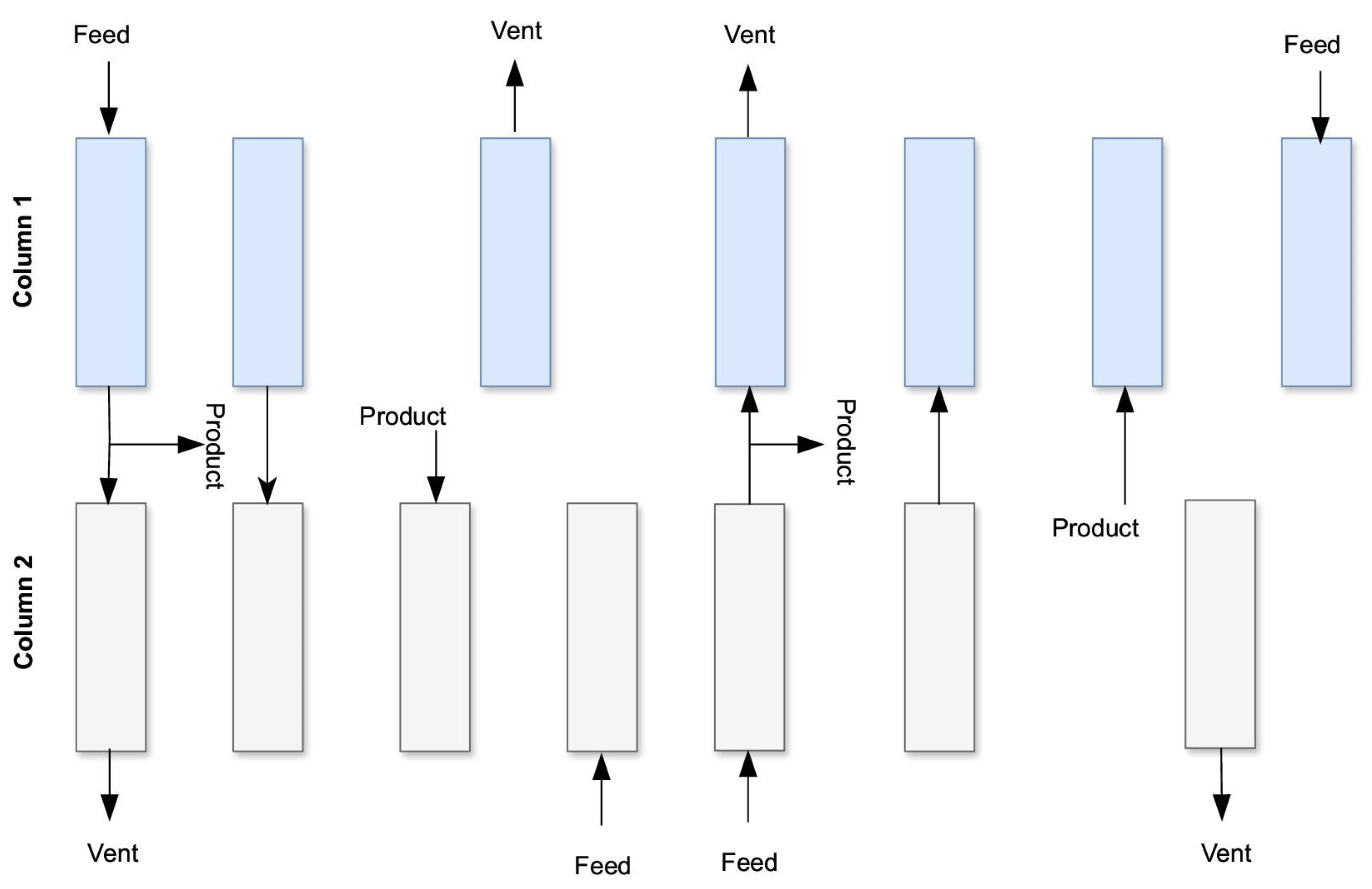
| Step | 1 | 2 | 3 | 4 | 5 | 6 |
|---|---|---|---|---|---|---|
| Column 1 | Blowdown ↓ | Pressure equalization ↓↑ | Compression (Pressurization) ↑ | Adsorption ↑ Purging ↓ | Pressure equalization ↓↑ | |
| Column 2 | Compression (Pressurization) ↑ | Adsorption ↑ Purging ↓ | Pressure equalization ↓↑ | Blowdown ↓ | Pressure equalization ↓↑ | |
| Step | 1 | 2 | 3 | 4 | 5 | 6 | 7 | 8 |
|---|---|---|---|---|---|---|---|---|
| Column 1 | Adsorption (180 s) | Depressurizing pressure equalization (20 s) | Depressurization (8 s) | Pressurizing pressure equalization (20 s) | Pressure equalization ↓↑ | Backfill (4 s) | Feed pressurization (4 s) | |
| Column 2 | Purge (180 s) | Pressurizing pressure equalization (20 s) | Backfill (4 s) | Feed pressurization (4 s) | Depressurizing pressure equalization (20 s) | Pressure equalization ↓↑ | Depressurization (8 s) | |
| Step | 1 | 2 | 3 | 4 | 5 | 6 |
|---|---|---|---|---|---|---|
| Column 1 | PR | AD | DPE | BD | PG | PPE |
| Column 2 | BD | PG | PPE | PR | AD | DPE |
| Time, s | 15 | 200 | 10 | 15 | 200 | 10 |
| Step | 1 | 2 | 3 | 4 | 5 | 6 | 7 | 8 | 9 | 10 | 11 | 12 |
|---|---|---|---|---|---|---|---|---|---|---|---|---|
| Column 1 | AD | FDPE | SDPE | BD | PG | FPPE | SPPE | PR | ||||
| Column 2 | SPPE | PR | AD | FDPE | SDPE | BD | PG | FPPE | ||||
| Column 3 | BD | PG | FPPE | SPPE | PR | AD | FDPE | SDPE | ||||
| Column 4 | FDPE | SDPE | BD | PG | FPPE | SPPE | PR | AD | ||||
| Time, s | 15 | 180 | 15 | 15 | 180 | 15 | 15 | 180 | 15 | 15 | 180 | 15 |
| Step | 1 | 2 | 3 | 4 | 5 | 6 | 7 | 8 |
|---|---|---|---|---|---|---|---|---|
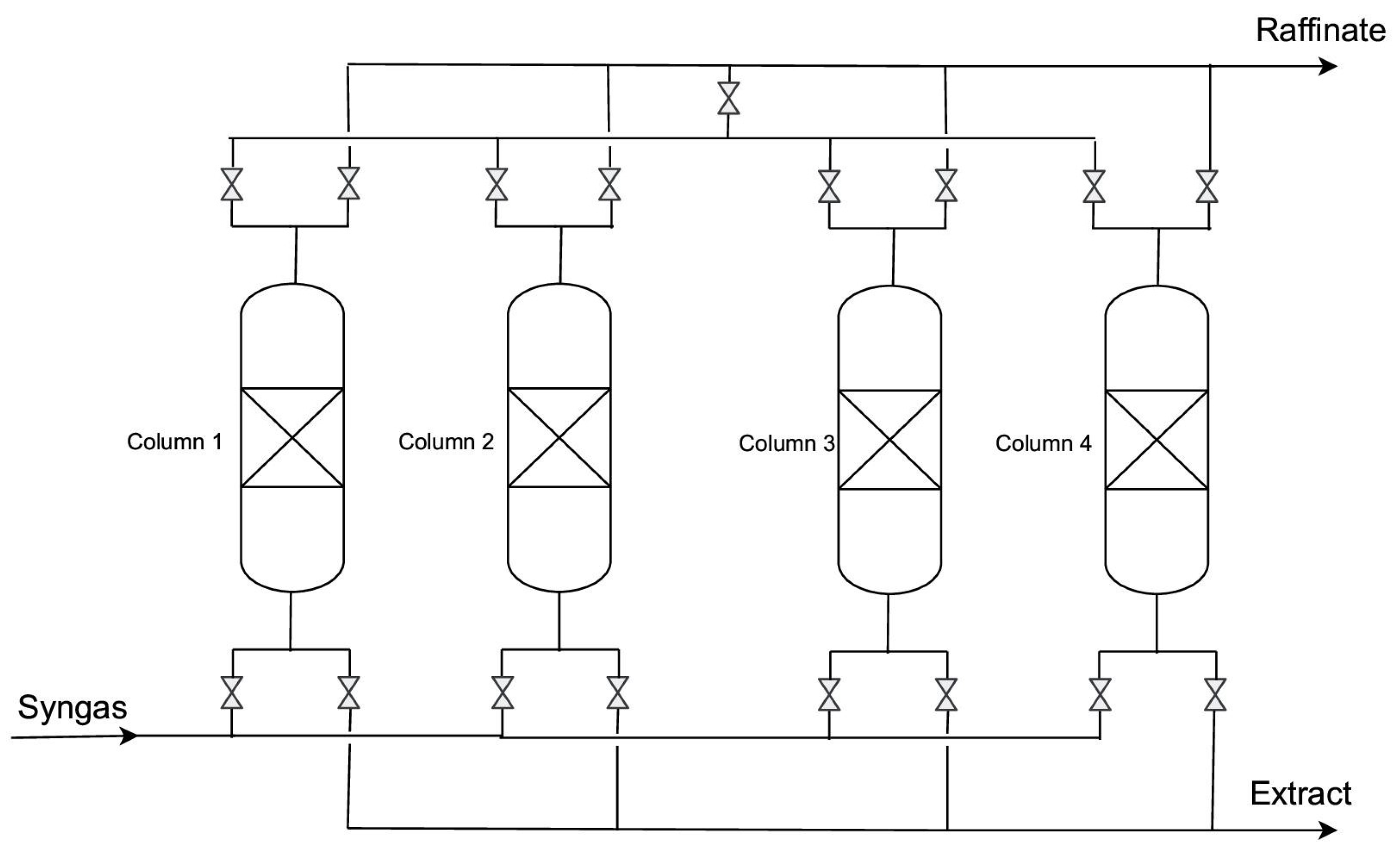
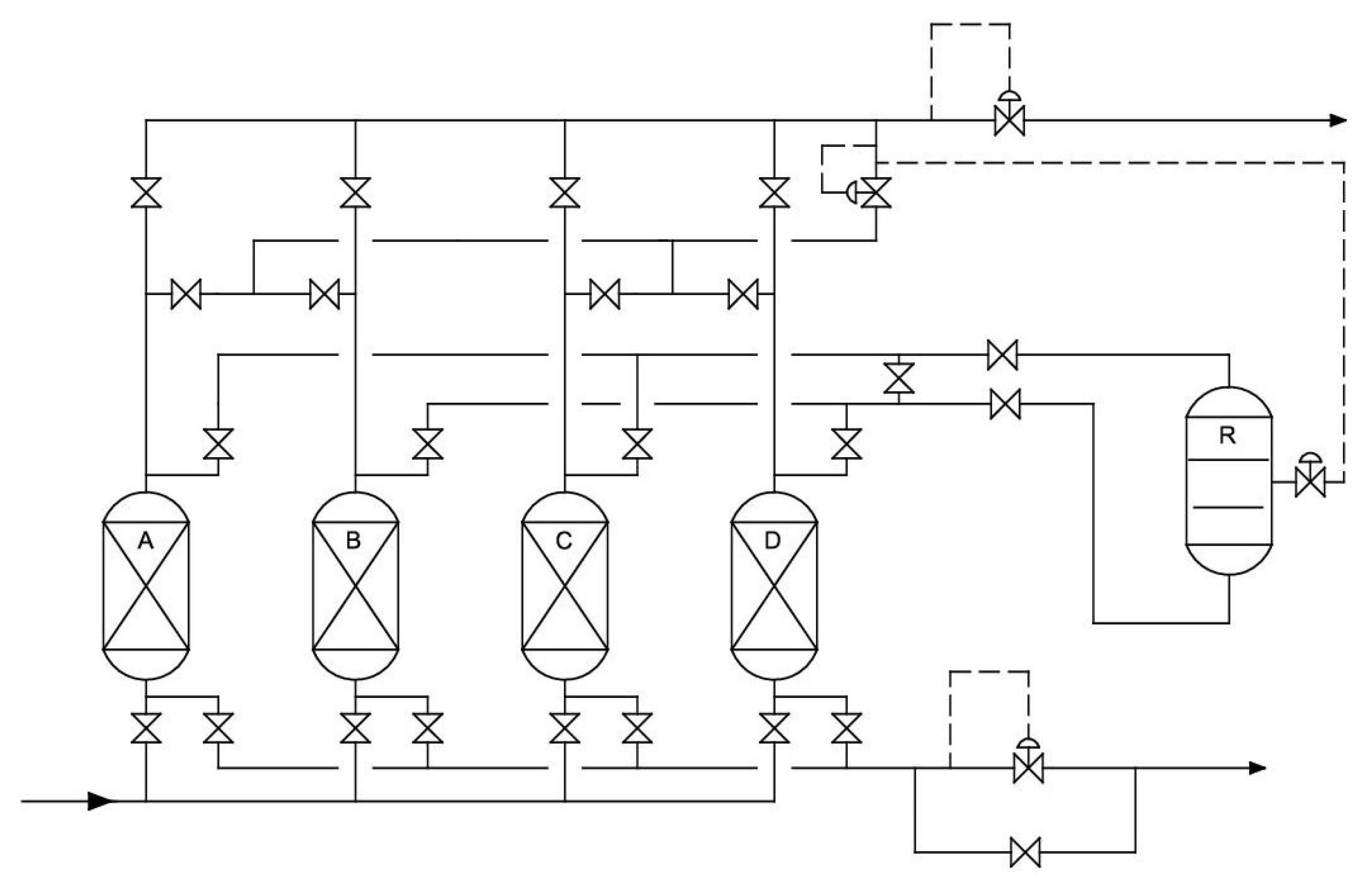
| Column 1 | ADSORPTION ↑ | Pressure equalization 2 ↑ | Provide purge ↑ | Blowdown ↓ | Purge ↓ | Pressure equalization 1 ↓ | Compression with the product ↑ | |
| Column 2 | Pressure equalization 1 ↓ | Compression with the product ↑ | ADSORPTION ↑ | Pressure equalization 2 ↑ | Provide purge ↑ | Blowdown ↓ | Purge ↓ | |
| Column 3 | Blowdown ↓ | Purge ↓ | Pressure equalization 1 ↓ | Compression with the product ↑ | ADSORPTION↑ | Pressure equalization 2 ↑ | Provide purge ↑ | |
| Column 4 | Pressure equalization 2 ↑ | Provide purge ↑ | Blowdown ↓ | Purge ↓ | Pressure equalization 1 ↓ | Compression with the product ↑ | ADSORPTION ↑ | |
| Direction of gas flow between columns | ||||||||
| Flow | 4→2 | 4→3 | 1→3 | 1→4 | 2→4 | 2→1 | 3→1 | 3→1 |
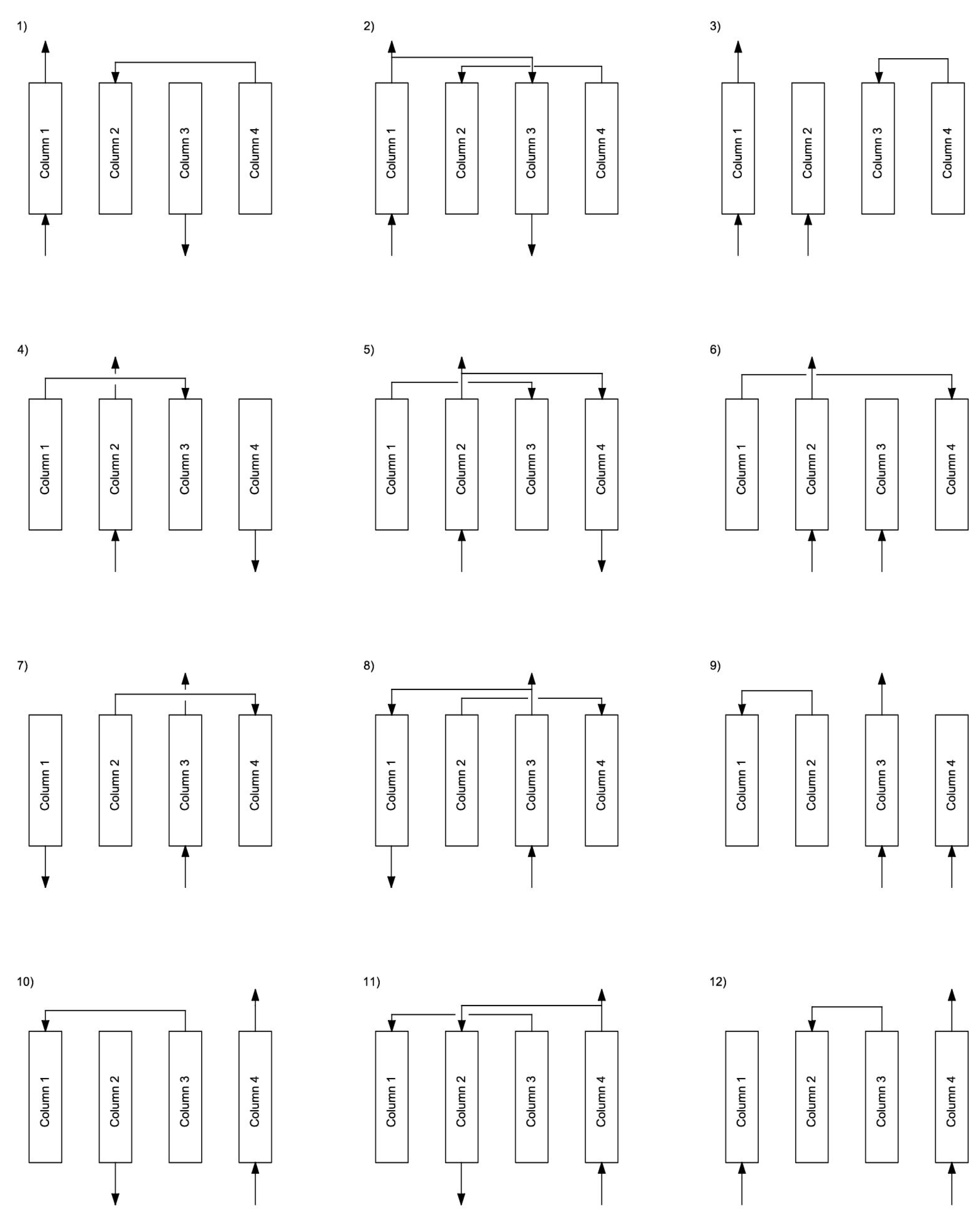
| Step | 1 | 2 | 3 | 4 | 5 | 6 | 7 | 8 | 9 | 10 | 11 | 12 |
|---|---|---|---|---|---|---|---|---|---|---|---|---|
| Column 1 | ADSORPTION | EQ1 ↑ | CD ↑ | EQ2 ↑ | CD ↓ | Purge ↓ | EQ2 ↓ | EQ1 ↓ | R ↓ | |||
| Column 2 | CD ↓ | Purge ↓ | EQ2 ↓ | EQ1 ↓ | R ↓ | ADSORPTION | EQ1 ↑ | CD ↑ | EQ2 ↑ | |||
| Column 3 | EQ1 ↑ | CD ↑ | EQ2 ↑ | CD ↓ | Purge ↓ | EQ2 ↓ | EQ1 ↓ | R ↓ | ADSORPTION | |||
| Column 4 | EQ1 ↓ | R ↓ | ADSORPTION | EQ1 ↑ | CD ↑ | EQ2 ↑ | CD ↓ | Purge ↓ | EQ2 ↓ | |||
| Process Name | Licensor | Adsorbent | Number of Columns | Inlet Gas | H2 Purity (%) | H2 Recovery (%) | Capacity (m3n h−1) |
|---|---|---|---|---|---|---|---|
| Poly-bed | Union Carbide (UOP Honeywell) | AC + zeolite 5A | 10 | SMROG 21 bar | 99.999 | 86 | 1000–120,000 |
| Lofin | Toyo Engineering | silikagel/AC | 4 | ROG 28 bar | 99.6 | 86.3 | 5000–200,000 |
| Gemini | Air Products | AC/zeolite 5A | 9 | SMROG 18 bar | 99.99 | 87 | 1000–400,000 |
| Adsorbent | Surface Area, (m2/g) | CO2 Loading @ 25 °C, 1 bar, (mol/kg) | −ΔHads, (kJ/mol) |
|---|---|---|---|
| Activated carbon | 700–1800 | 1.32–4.18 | 22–37 |
| Silica gel-based | 700–1500 | 1.4–3.01 | 40–90 |
| Zeolite | 400–925 | 3.29–5.16 | 28–69 |
| Metal–organic framework (MOF) | 1000–10,000 | 2.22–3.93 | 40–90 |
| Adsorbent | CO2 Loading (mmol/g) | CH4 Loading (mmol/g) | CO2/CH4 Selectivity | ||||||
|---|---|---|---|---|---|---|---|---|---|
| P = 2 bar | P = 4 bar | P = 6 bar | P = 2 bar | P = 4 bar | P = 6 bar | P = 2 bar | P = 4 bar | P = 6 bar | |
| SAPO-34 | 2.4 | 3.0 | 3.4 | 0.63 | 1.0 | 1.3 | 3.8 | 3.0 | 2.6 |
| NORIT AC | 3.0 | 4.0 | 4.7 | 1.4 | 2.1 | 2.6 | 2.1 | 1.9 | 1.8 |
| ZSM-5 | 1.5 | 1.8 | 1.9 | 0.63 | 0.93 | 1.1 | 2.4 | 1.9 | 1.7 |
| Silicalite-1 | 1.7 | 2.0 | 2.1 | 0.63 | 0.89 | 1.0 | 2.7 | 2.2 | 2.0 |
| Zeolite 5A | 3.4 | 3.5 | 3.5 | 1.0 | 1.3 | 1.6 | 3.4 | 2.7 | 2.3 |
| Zeolite 13X | 3.7 | 4.5 | 4.7 | 0.94 | 1.6 | 2.0 | 3.9 | 2.8 | 2.3 |
| Author | Park et al. [74] 1998 | Ahn et al. [73] 2001 | Ahn et al. [76] 2012 | Golmakani et al. [85] 2017 | Golmakani et al. [51] 2020 |
|---|---|---|---|---|---|
| Inlet gas parameters | 5 cm/s, 17 bar, 303 K | 6–11 LSTP/min (5.55–10.2 m/s superficial velocity); 22 bar | 5–7 SLPM; 5–8 bar | 10 SLPM, 22 bar, 303 K | 10 SLPM |
| Inlet gas composition | Case 1: H2: 59.7%, CH4: 2.5%, CO: 23.0%, N2: 0%, CO2: 14.8% (case V). | H2: 56.4%, CH4: 26.6%, CO: 8.4%, N2: 5.5%, CO2: 3.1% (base case). Also, “higher nitrogen” and “no nitrogen” compositions considered. | H2: 38%, CO2: 50%, CH4: 1%, CO: 1%, N2: 10% (coal gas from iron and steel processes feed). | H2: 75%, CO2: 18%, CH4: 3.2%, CO: 0.7%, N2: 3.1% (SMR syngas feed). | H2: 75%, CO2: 18% (20%), CH4: 3.2%, CO: 0.7%, N2: 3.1% (1.1%). |
| PSA column parameters | Internal diameter: 2.46 cm; length: 120 cm | Internal diameter: 3.71 cm; length: 100 cm | Internal diameter: 3.5 cm; length: 100 cm | Length: AC: 45 cm + Zeolite: 35 cm; ID: 3.5 cm | Length: Total 120 = AC: 84.5 cm + Zeolite: 35.5 cm; ID: 3.5 cm |
| AC/MS 5A ratio | Varied, but 60 cm:60 cm | Varied, but the best 50:50 or 0.32 (zeolite-dominated) | Activated carbon 7: zeolite 3 | Activated carbon (45 cm) and zeolite 5A (35 cm) used in two-layer beds. | Activated carbon and zeolite 5A layers in all configurations. |
| PSA proces concept | Breakthrough curves | 7 steps with 2 column (beds) layers | 6 steps with 2 columns and 12 steps with 4 columns used | 12 steps with 4 column (beds) layers; 90 s adsorption time | 16 steps (vacuum-assisted regeneration) with 4 column (beds) layers. |
| Experimental or Simulated | Both | Both | Isothermal dynamic mode | Simulated | Simulated |
| Performance (Purity/Recovery | - | Purity: 99.99–99.9999%; Recovery: 70–90% | Purity: 97.54%; Recovery: 60.39% | Purity: 99.99–99.9999%; CO < 0.2 ppm; Recovery: ~75% | Purity: 99.99%; Recovery: 47–55% |
| Parameter | Value | Unit |
|---|---|---|
| Capacity | 5–20 | dm3n/min |
| Number of TSA columns | 2 | pieces |
| TSA temperature | up to 150 | °C |
| Number of PSA columns | 4 | pieces |
| PSA pressure | up to 15 | bar |
| TSA adsorber diameter | 60 | mm |
| TSA column total height | 1 | m |
| PSA adsorber diameter | 50 | mm |
| PSA column total height | 1.2 | m |
| Inlet gas buffer tank volume | 27.2 | dm3 |
| High (HI) pressure gas buffer tank volume | 4.8 | dm3 |
| Low (LO) pressure gas buffer tank volume | 7.2 | dm3 |
| Number of gas mass flowmeters | 2 | pieces |
| Model | 5A |
|---|---|
| Color | Light gray |
| Nominal pore diameter | 5 Angstroms |
| Shape | Sphere |
| Diameter, mm | 3.0–5.0 |
| Size ratio up to grade, % | ≥98 |
| Bulk density, (g/mL) | ≥0.70 |
| Crushing strength, N | ≥100/piece |
| Static H2O adsorption, % | ≥22 |
| Water content, % | ≤1 |
| Typical chemical formula | 0.7CaO × 0.3Na2O × Al2O3 × 2SiO2 × 4.5H2O SiO2:Al2O3 ≈ 2 |
| Process Parameters | Gas Composition | AC/Zeolite Ratio | |
|---|---|---|---|
| Inlet gas capacity at about 10 dm3n/h; ambient temperature; adsorption pressure 8–9 bar | Syngas | 1:1 | 1.6:1 |
| WGS syngas | 1:1 | 1.6:1 | |
| Task | Syngas | WGS Syngas | ||
|---|---|---|---|---|
| Gas composition | Syngas | WGS syngas | ||
| Number of columns involved in the process | 2 | 4 | 2 | 4 |
| Gas flow rate | 10 dm3n/min | 10 dm3n/min | 10 dm3n/min | 10 dm3n/min |
| Adsorption temperature | ambient | ambient | ambient | ambient |
| Adsorption pressure | 8–9 bara | 8–9 bara | 8–9 bara | 8–9 bara |
| P/F ratio | 0.1 | 0.1 | 0.1 | 0.1 |
| PSA process concept | Berlin concept | Linde Gas concept | Berlin concept | Linde Gas concept |
| PSA phase time | Determined by the breakthrough experiments | Determined by the breakthrough experiments | ||
Disclaimer/Publisher’s Note: The statements, opinions and data contained in all publications are solely those of the individual author(s) and contributor(s) and not of MDPI and/or the editor(s). MDPI and/or the editor(s) disclaim responsibility for any injury to people or property resulting from any ideas, methods, instructions or products referred to in the content. |
© 2025 by the authors. Licensee MDPI, Basel, Switzerland. This article is an open access article distributed under the terms and conditions of the Creative Commons Attribution (CC BY) license (https://creativecommons.org/licenses/by/4.0/).
Share and Cite
Krótki, A.; Bigda, J.; Spietz, T.; Ignasiak, K.; Matusiak, P.; Kowol, D. Performance Evaluation of Pressure Swing Adsorption for Hydrogen Separation from Syngas and Water–Gas Shift Syngas. Energies 2025, 18, 1887. https://doi.org/10.3390/en18081887
Krótki A, Bigda J, Spietz T, Ignasiak K, Matusiak P, Kowol D. Performance Evaluation of Pressure Swing Adsorption for Hydrogen Separation from Syngas and Water–Gas Shift Syngas. Energies. 2025; 18(8):1887. https://doi.org/10.3390/en18081887
Chicago/Turabian StyleKrótki, Aleksander, Joanna Bigda, Tomasz Spietz, Karina Ignasiak, Piotr Matusiak, and Daniel Kowol. 2025. "Performance Evaluation of Pressure Swing Adsorption for Hydrogen Separation from Syngas and Water–Gas Shift Syngas" Energies 18, no. 8: 1887. https://doi.org/10.3390/en18081887
APA StyleKrótki, A., Bigda, J., Spietz, T., Ignasiak, K., Matusiak, P., & Kowol, D. (2025). Performance Evaluation of Pressure Swing Adsorption for Hydrogen Separation from Syngas and Water–Gas Shift Syngas. Energies, 18(8), 1887. https://doi.org/10.3390/en18081887