Abstract
Proton Exchange Membrane Fuel Cells (PEMFCs), recognised for their high efficiency and zero emissions, represent a promising solution for automotive applications. Despite their potential, durability challenges under real-world automotive operating conditions—arising from chemical, mechanical, catalytic, and thermal degradation processes intensified by contaminants—limit their broader adoption. This review aims to systematically assess recent advancements in understanding and modelling PEMFC degradation mechanisms. The article critically evaluates experimental approaches integrated with advanced physicochemical modelling techniques, such as impedance spectroscopy, microstructural analysis, and hybrid modelling approaches, highlighting their strengths and specific limitations. Experimental studies conducted under dynamic, realistic conditions provide precise data for validating these models. The review explicitly compares physics-based, data-driven, and hybrid modelling strategies, discussing trade-offs between accuracy, computational demand, and generalizability. Key findings emphasise that hybrid models effectively balance precision with computational efficiency. Finally, the article identifies apparent research gaps. It suggests future directions, including developing degradation-resistant materials, improved simulation methodologies, and intelligent control systems to optimise PEMFC performance and enhance operational lifespan.
1. Introduction
Growing global energy demand and the environmental harm caused by fossil fuels have spurred the development of sustainable and eco-friendly energy solutions. A promising option is the employment of hydrogen energy as an alternative source for electricity generation. Fuel cells (FCs) play a pivotal role in this scenario. They efficiently convert chemical energy from various fuels like methanol and hydrogen into electricity, with hydrogen FCs producing zero carbon emissions. There are several types of FCs, each distinguished by their electrolytes and fuels, including Solid Oxide Fuel Cells (SOFCs), Polymer Electrolyte Membrane Fuel Cells (PEMFCs), Molten Carbonate Fuel Cells (MCFCs), Direct Methanol Fuel Cells (DMFCs), Alkaline Fuel Cells (AFCs), Phosphoric Acid Fuel Cells (PAFCs), and Alkaline Anion Exchange Membrane Fuel Cells (AEMFs). PEMFCs can be considered the most sustainable with various usages, mainly due to their high efficiency, low emission of greenhouse gases, and low working temperature; they have recently attracted attention as a potential alternative for the automotive industry [1,2,3,4,5,6].
Proton Exchange Membrane Fuel Cells (PEMFCs) are fuel cells that operate using pure hydrogen as fuel and offer several advantages, such as high specific power, excellent efficiency, low noise, and solid performance [7,8,9,10,11]. These qualities make PEMFCs highly promising across various fields, such as transportation, mobile power generation, and aerospace. With the global focus on reducing emissions, adopting electric vehicles, particularly those powered by fuel cells and batteries, is gaining momentum as a practical solution. The automotive sector, in particular, has shown strong interest in hydrogen PEMFC technology, with significant manufacturers heavily investing in developing FC vehicles. PEMFC technology-powered vehicles such as the Toyota Mirai and Hyundai NEXO, the most widely available on the market, are at the forefront of research due to their zero emissions, high energy conversion efficiency, and other notable benefits. However, alongside this growing interest in automotive PEMFCs, specific technical challenges have come to the fore—particularly concerning their durability and reliability under dynamic operating conditions. One of the key issues is catalyst degradation, particularly of platinum particles, which results in a reduction in electrochemically active surface area and subsequent performance losses. Recent research shows that under voltage cycling, higher voltages significantly accelerate the dissolution and agglomeration of Pt particles, leading to a drop in ECSA of up to 40% and particle growth of over 20% during long-term testing [12]. In addition, start–stop cycles can cause corrosion of carbon supports, leading to physical deterioration and loss of catalytic activity [13]. Dynamic load profiles further increase the risk of platinum migration and voltage loss, thereby accelerating fuel cell degradation [14]. In response to these challenges, recent research has increasingly focused on the application of artificial intelligence and predictive algorithms. Advanced hybrid models, such as BiTCN-BiGRU-ELM, allow for accurate prediction of degradation trends and remaining useful life, thereby enabling efficient maintenance and enhancing operational reliability [15]. In parallel, the deployment of AI in fault diagnosis enables real-time anomaly detection and optimisation of fuel cell operation [16]. These approaches represent a significant advancement in extending the PEMFC lifespan and supporting their wider deployment in the automotive industry.
These improvements in sustainable mobility represent a critical step in slowing emissions growth as society moves towards low-carbon energy sources. Figure 1 illustrates the components of a disassembled PEMFC, displaying gas flow channels for hydrogen and oxygen (in carbon-based bipolar plates) as well as the membrane electrode assembly (MEA). Despite their numerous advantages, the limited lifespan of PEMFCs still hinders their commercialisation. Over prolonged operation periods, PEMFC performance gradually deteriorates due to intricate operational conditions and component ageing, eventually reaching the minimum acceptable threshold [17]. Below is a description focused on the function of the individual parts and relevant degradation mechanisms [11,18,19,20,21,22].
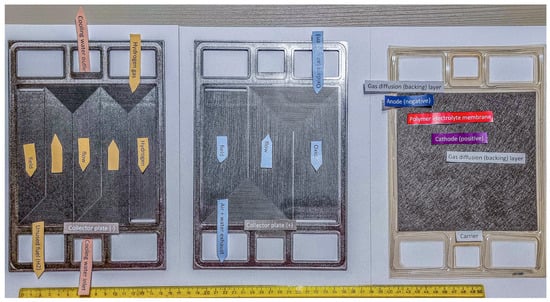
Figure 1.
Example of a disassembled PEM.
The hydrogen section, situated on the anode side, introduces hydrogen gas through the channels of the carbon bipolar plate into the gas diffusion layer (GDL) and subsequently into the catalyst layer. Within the catalyst layer, hydrogen splits into protons and electrons, enabling the electrochemical reaction to occur [23,24]. Degradation mechanisms in the bipolar plate include mechanical wear, which arises over extended usage due to structural deformation, adversely impacting gas distribution [25], and channel blockages caused by excessive water formation or contaminants [26].
The oxygen section, located on the cathode side, channels oxygen through the bipolar plate, transporting it via the GDL to the catalyst layer, where it reacts with protons from the membrane and electrons from the external circuit to produce water [27]. Degradation mechanisms affecting this section include carbon corrosion, which typically occurs under high potentials during start–stop cycles, leading to oxidation of the carbon support [28], and channel blockages caused by water or particulates obstructing oxygen flow [29].
MEA, which consists of a proton-conductive membrane (e.g., Nafion), catalyst layers, and gas diffusion layers, is susceptible to both mechanical and chemical degradation. Mechanical degradation is characterised by the formation of cracks and perforations, often caused by uneven mechanical stress during assembly or operation [30]. Additionally, humidity cycling, which involves repeated swelling and drying of the membrane, induces microcracks that compromise its mechanical integrity [31]. Chemical degradation, on the other hand, is driven by attacks from reactive species, such as hydroxyl and peroxide radicals, generated during the decomposition of hydrogen peroxide. These radicals degrade the polymer chains, leading to membrane thinning, reduced proton conductivity, and the formation of pinholes [32]. The effects of chemical degradation are further exacerbated by ionomer contamination from metallic ions, such as Fe2+ and Cu2+, which catalyse these destructive processes [33].
While mitigation strategies such as reinforced membranes, stabilised catalyst coatings, and antioxidant additives have shown some promise, durability under real automotive conditions remains a challenge. Studies show that during dynamic drive cycles, PEMFCs are exposed to rapid temperature and humidity fluctuations, mechanical vibrations, and transient gas flow profiles, which collectively accelerate both mechanical fatigue and chemical ageing processes in the MEA [34]. Furthermore, microstructural changes such as catalyst particle migration, delamination of catalyst layers, and interfacial damage between layers are observed after prolonged automotive operation, indicating complex degradation mechanisms that are still not fully understood [35]. These knowledge gaps highlight the need for deeper insight into coupled mechanical–chemical degradation pathways and for the development of MEAs tailored specifically to automotive cycling profiles.
PEMFCs produce electricity and a substantial amount of heat, requiring effective management to sustain peak performance. This involves supplying a higher stoichiometric ratio of reactant gases to the PEMFCs and utilising various gas management techniques, such as dead-end anode operation and exhaust gas recirculation [11,36]. In fuel cell vehicles, hydrogen is stored in high-pressure tanks. However, since PEMFCs function near ambient pressure, it is not feasible to reinject unreacted hydrogen into storage without a high-pressure compressor, which is impractical for vehicles. Excess hydrogen must be vented without a recirculation system, significantly reducing fuel utilisation and vehicle efficiency. Researchers have proposed various hydrogen recirculation methods to mitigate this issue, including using an ejector or a hydrogen recirculation pump. Among these, the ejector is particularly advantageous, as it requires less power, operates more quietly, and has greater durability than mechanical pumps, making it an effective solution for fuel cell systems [11,37,38,39,40,41].
This is particularly relevant in automotive applications, where PEMFC systems operate under highly variable and often harsh conditions that directly influence degradation pathways. Recent studies have shown that temperature fluctuations, humidity cycling, and load transients cause significantly different degradation rates across components, especially in membrane and catalyst layers [42]. Moreover, the interplay of mechanical stress with electrochemical ageing mechanisms remains poorly understood in real driving scenarios, where startup/shutdown cycles, freeze/thaw events, and partial load operation combine in complex ways [43]. This gap in mechanistic understanding presents a critical barrier to the design of long-lasting, vehicle-optimised PEMFC stacks. Therefore, Section 2 provides an in-depth overview of the principal degradation mechanisms observed under automotive conditions and highlights the most urgent areas for future research.
FC systems integrated into a vehicle are exposed to demanding working conditions like variations in dynamic load, air pollution, humidity and temperature, low ambient temperature, shocks, and vibrations. These influences can lead to an acceleration in the degradation of system components. Hence, advanced diagnostic and prognostic tools tailored to various configurations and energy management strategies are crucial for assessing and enhancing performance in terms of reliability and longevity. Selecting practical prognostic and diagnostic tools depends on a thorough knowledge and control of the working conditions, faults, and degradation mechanisms at the system level [24,44,45,46,47,48].
The authors’ primary goal is to write a comprehensive publication dealing with the mechanisms and modelling of effects on the degradation processes of a proton exchange membrane (PEM) in FC. This publication is intended to serve as an input for budding scientists. This article aims to provide a critical and comprehensive overview of chemical, thermal, and mechanical degradation mechanisms in PEMFCs and address degradation caused by contaminants. Additionally, it gives an overview of existing modelling approaches to model all components of an FC system by considering degradation in performance concerning working conditions and component ageing.
The review article is innovative on the following points:
- Overview of PEMFC degradation mechanisms: the article provides a comprehensive overview of the various degradation mechanisms of Polymer Electrolyte Membrane Fuel Cells (PEMFCs), which include chemical degradation of the membrane, mechanical degradation of the components, electrochemical degradation of the catalyst, and degradation processes at the electrodes.
- Linking experimental results to degradation models: the authors stress the importance of linking experimental data obtained under realistic operating conditions to predictive and theoretical models, leading to a more accurate understanding of the interactions between operating conditions and degradation phenomena.
- Critical evaluation of current prediction methods: the article critically evaluates the available methods and models for PEMFC lifetime prediction, discusses their advantages and limitations, and highlights the need for further development of more robust prediction tools.
- New diagnostic methods for monitoring degradation: the review includes modern diagnostic methods such as impedance spectroscopy, microstructural analysis, and advanced imaging techniques that allow detailed monitoring of the fuel cell condition and identification of early stages of degradation.
- Future research directions: the authors define key areas for future research, which include the development of new materials with higher degradation resistance, improved simulation techniques for more accurate lifetime prediction, and the implementation of intelligent control systems to minimise degradation effects in PEMFCs.
The article is structured into seven main sections. Section 1 introduces the topic of the review article and describes the innovation, the authors’ goal, and their motivation. Section 2 provides an overview of the main degradation mechanisms that affect the performance and lifetime of the proton exchange membrane. It focuses on how various physical and chemical influences contribute to the degradation of individual components, including the membrane, catalyst layer, diffusion layers, and bipolar plates. The chapter discusses mechanical degradation (e.g., forming cracks and perforations in membranes) and chemical processes, such as oxidation and corrosion, that degrade fuel cell performance. Section 3 examines how different operating conditions and vehicle load regimes affect fuel cell degradation. It focuses on other modes, such as start/stop cycles, dynamic loading, idling, and high load. It describes how each of these modes contributes explicitly to the degradation of cell components. For example, start/stop cycling causes carbon corrosion, which reduces the active surface area of the catalyst, while high load increases chemical corrosion of the membrane. Thus, the chapter analyses how different driving modes accelerate degradation and reduce fuel cell lifetime. Section 4 focuses on different approaches for predicting fuel cell degradation. It describes three main types of models: physics-based, data-driven, and hybrid. Physics-based models offer detailed and accurate simulations based on fundamental physical laws, but their drawback is their high computational complexity. Data-driven models work with historical data and are computationally less demanding but cannot generalise to new conditions. Hybrid models combine both approaches, attempting to balance accuracy and computational efficiency. The chapter evaluates the advantages and disadvantages of each model and their use in predictive maintenance, which can potentially extend the life of fuel cells in the challenging conditions of automotive applications. Section 5 introduces equivalent circuit models (ECM) to simplify the electrochemical behaviour of PEM fuel cells, enabling real-time diagnostics and monitoring of degradation. Changes in ECM parameters, such as increased resistance or decreased capacitance, indicate membrane drying, catalyst degradation, or contamination, which can be tracked using electrochemical impedance spectroscopy (EIS). While ECMs offer computational efficiency, physically based models provide a more detailed but complex description of fuel cell processes. Atomistic and molecular modelling, including density functional theory (DFT) and molecular dynamics (MD), helps understand catalyst dissolution, membrane degradation, and impurity effects at a microscopic level. Integrating ECM with atomistic simulations and machine learning improves degradation prediction and material optimisation for enhanced fuel cell longevity. Multiscale modelling efforts bridge the gap between atomistic insights and real-world fuel cell performance, ensuring more accurate lifetime predictions. Section 6 focuses on approaches to modelling degradation using empirically collected data. This chapter describes how historical and experimental data can help predict fuel cell degradation and performance without complex physical models. Data-driven models enable fast and efficient predictions, although they require large amounts of data for accurate results. The chapter also focuses on the various data processing techniques and algorithms used for fuel cell lifetime analysis and prediction, contributing to more effective use of these systems in real-world applications. Section 7 combines physical and data-driven approaches for modelling fuel cell degradation. Hybrid models seek to combine the advantages of physical models, which provide accurate simulations based on fundamental principles, and data-driven models, which are less computationally intensive and allow fast predictions. This chapter details how hybrid models use physical equations for the main degradation mechanisms while data-driven algorithms handle complex and challenging conditions. Hybrid models aim to increase the accuracy and efficiency of predictive fuel cell maintenance and deploy them in real-world applications where high reliability and system performance are expected. Section 8 summarises the main findings on the degradation mechanisms of PEMFCs and their modelling capabilities. The chapter emphasises that a detailed understanding of degradation processes is essential for extending the lifetime of fuel cells, which is particularly crucial for their deployment in the automotive industry. For better illustration, the main sections of the article are illustrated in Figure 2.
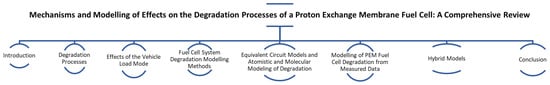
Figure 2.
Article main section overview.
2. Degradation Processes
The PEMFC is an attractive candidate for automotive energy generation due to its high efficiency and lack of emissions. Nonetheless, its broader adoption is hampered by durability and service life issues. Enhancing the durability of FC components is crucial for their commercial success. A detailed characterisation of each component is necessary to identify and mitigate deterioration mechanisms, thereby prolonging the lifespan of the FC. The automotive industry’s demanding operational conditions particularly accelerate the ageing of FCs, leading to various DMs that necessitate a thorough understanding. Figure 3 refers to a detailed breakdown of DM.
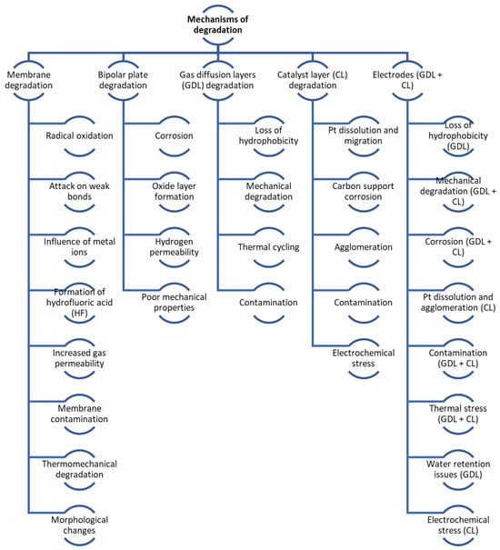
Figure 3.
Degradation processes and mechanisms overview.
Degradation in FCs can be either mechanical or chemical in nature. As the FC is used, its parts degrade, especially the membrane (leading to cracks and pinholes), the catalyst layer (including platinum particle Ostwald ripening and carbon corrosion), diffusion layers (like carbon support surface oxidation), and bipolar plates. Table 1 in the referenced document details the primary DMs in FCs, while Table 2 illustrates the effects of vehicle load regimes on degradation [49]. Figure 4 shows the main mechanisms of mechanical and chemical degradation of PEMFC.

Table 1.
Main DMs of FCs [50].
Table 2.
Degradation mechanisms of membranes.
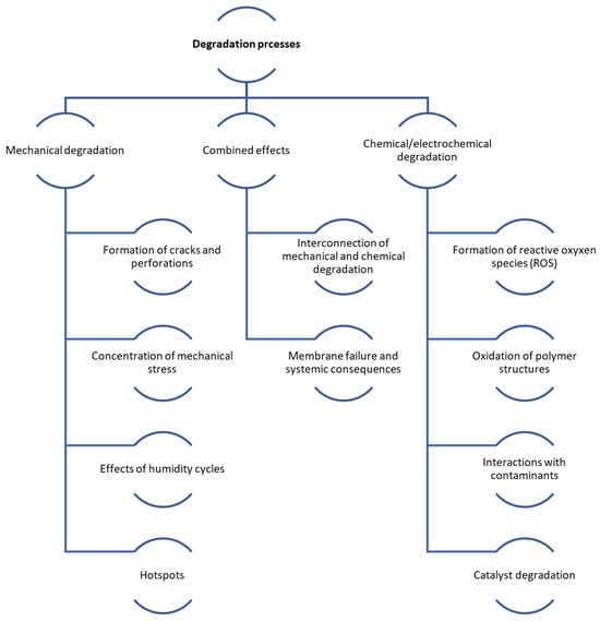
Figure 4.
Scheme of mechanical and chemical degradation processes in PEMFCs.
Considering the design of a hybrid FC system in a vehicle, there are numerous interactions among its components. The system introduces hydrogen to the FC’s anode to initiate chemical reactions, with its inlet pressure regulated by a pressure controller. An oxidant (air) is supplied to the cathode through an airline, which is essential for starting the chemical reactions. The mass flow of air at the cathode inlet and its pressure at the outlet are regulated using a compressor. To prevent membrane dehydration, which leads to cracks and holes in the electrolyte, air humidity (oxidant) is controlled, incorporating a passive humidifier between the FC system and the air compressor. Additionally, a cooling unit is employed to keep an optimal internal temperature within the FC.
The chemical reactions taking place in the FC system are exothermic. Excessive temperature will result in the components destruction. For adjusting this temperature, fans connected to the water circuit and heat exchanger are controlled. The power converter converts the electrical energy from the FC set output to the DC bus.
The battery provides electric dynamics. Load changes and electric dynamics adversely affect FC degradation. Hybrid electric systems aim to intelligently distribute energy between the battery and FC. A DC–DC converter adjusts the FC current to minimise load changes and current dynamics while the battery provides dynamic power under load. In addition, when there are low load demands, such as when the vehicle is idling, the battery will be recharged by the FC [46].
2.1. Mechanical Degradation
Mechanical degradation of membranes in PEMFCs is a significant issue impacting their durability and performance. It can lead to rapid failure due to cracks, perforations, pinholes, and membrane rupture, often resulting from manufacturing defects or improper assembly of the MEA. These failures are closely associated with microstructural changes, such as membrane swelling and shrinking during operation, which compromise mechanical integrity [51].
During the high current density operation of PEMFCs, the accumulation of liquid water within the GDL emerges as a critical issue, commonly referred to as electrode flooding. This phenomenon obstructs effective gas transport to the reaction sites, leading to a significant decline in cell performance. Recent studies have shown that implementing a gradient porosity structure within the GDL substantially improves liquid water removal towards the drainage channels, thereby mitigating flooding risks [52]. Additionally, enhancing the surface hydrophobicity of the GDL has been proven to facilitate water removal and ensure more stable operation under high humidity and current density conditions [53,54]. Effective water management is, therefore, a crucial prerequisite for achieving long-term stability and high performance in PEM fuel cells.
During the assembly of PEMFCs, the interfaces between the surfaces of bipolar plates, channels, and sealing edges are subjected to uneven mechanical stress, which can cause stress concentration and promote crack initiation [23,55]. The stresses generated at these critical points can trigger microscopic cracks, which gradually expand and cause macroscopic damage to the membrane. This process often remains unnoticed until a substantial reduction in FC performance is observed.
Local hotspots, caused by exothermic reactions between the oxidant and reductant, can significantly increase membrane stress and result in catastrophic failure. These hotspots often arise from uneven gas distribution or compromised transport properties of the membrane, further exacerbating local stress [56,57]. Prolonged exposure of the membrane to such conditions can also lead to the degradation of polymer chains, weakening their chemical resistance.
The membrane is exposed to high-humidity cycles during operation, which cause repeated swelling and shrinking. This phenomenon, known as the “humidity cycle”, induces mechanical stress that disrupts the material cohesion of the membrane. This process reduces the mechanical robustness of the membrane, with humidity fluctuations being particularly critical, as they cause degradation more rapidly than temperature cycles. The increased amplitude of humidity cycles can significantly shorten the membrane’s lifespan [25,27]. These effects lead to the formation of microcracks and microdefects, which impair gas permeability and resistance to reactant crossover [24].
Catalyst migration on the membrane surface and gasket degradation further reduce membrane ductility and mechanical strength. Catalyst migration can also disrupt the electrode layer and impair its electrical conductivity, deteriorating the overall system efficiency [31]. Additionally, catalysts may undergo chemical attack due to interactions with reactants, accelerating their decay and promoting the formation of micropores in the membrane. Perforations and pinholes resulting from degradation allow reactants to cross over between electrodes, leading to the mixing of hydrogen and oxygen, unplanned exothermic reactions, and a significant decline in FC performance [30,57,58,59,60,61,62,63].
Mechanical degradation of membranes in PEMFCs involves a combination of factors, including uneven mechanical stress, cyclic humidity variations, catalyst migration, and the formation of local hotspots. These processes compromise membrane structure, induce defects, and reduce FC performance. Current challenges necessitate the development of more efficient materials and design approaches to minimise degradation and extend system lifespan.
To strengthen the discussion of degradation mechanisms, it is necessary to support the presented concepts with experimental case studies that reflect real-world PEMFC operation. For instance, ref. [64] developed a full-scale transient multiphysics model of PEMFCs and validated it experimentally. Their study demonstrated how humidity and temperature cycling contribute to stress accumulation and membrane deformation, ultimately leading to mechanical failure under dynamic load conditions [64]. Similarly, ref. [65] conducted combined chemical and mechanical accelerated stress testing on ePTFE-reinforced membranes and used X-ray computed tomography to observe membrane thinning and catalyst layer degradation. Their findings confirm the benefits of reinforcement in reducing hydrogen crossover and mechanical failure. Ref. [66] applied in situ 4D X-ray tomography to study hydrocarbon-based membranes, revealing crack formation and creep-induced membrane thinning at the electrode interfaces caused by differential swelling and mechanical mismatch [66]. In addition, ref. [67] experimentally evaluated membrane performance under sub-zero conditions, showing significant degradation of the catalyst-coated membrane (CCM) due to oxygen transport resistance and water management issues during cold starts [67]. These studies provide valuable insights and empirical validation of the degradation mechanisms discussed, reinforcing the importance of real-world testing in the development of more durable PEMFC membranes.
2.2. Chemical/Electrochemical Degradation
Chemical processes occurring on the anode and cathode catalysts in PEMFCs are a source of reactive oxygen species (ROS), including peroxide radicals, hydroperoxide radicals, and hydroxyl radicals. These species are primarily generated during operation at open-circuit voltage (OCV), where oxygen and hydrogen react in low-humidity conditions, leading to oxidation and degradation of membrane polymers [25,30].
Hydrogen peroxide, as a by-product of electrochemical reactions, can generate highly reactive hydroxyl radicals through Fenton reactions with transition metal ions (e.g., Fe2+ and Cu2+). These radicals attack the membrane structure, causing the breakdown of polymer chain bonds, which compromises its integrity and mechanical robustness [56].
The degradation mechanism begins with the oxidation of the side chains of the membrane, with sulfonic acid groups (SO3H) being particularly vulnerable to radical attack. This process reduces the membrane’s ability to conduct protons while also increasing the diffusion of reactants, such as oxygen, which accelerates further oxidation. Thinning of the membrane due to chemical degradation often results in the formation of microscopic defects and perforations, which can escalate into macroscopic failures. This allows gaseous reactants to penetrate between electrodes, creating localised hotspots and catastrophic failure of the FC [31]. It is hypothesised that this effect involves the expansion of polymer end groups or the scission of polymer chains, as reported in studies [68,69,70,71,72,73,74].
Recent experimental studies have confirmed these mechanisms and provided valuable data to better understand membrane degradation. For example, ref. [75] developed a coupled model of PEMFC operation and membrane chemical degradation and validated it against accelerated stress testing. They demonstrated that membrane thinning, mass loss, and proton conductivity decline are strongly dependent on voltage, temperature, and humidity, with degradation peaking at 80 °C and 60% relative humidity.
Another study by [76] introduced an ex situ accelerated degradation protocol to evaluate Nafion membranes. The team used hydrogen permeation current and voltage loss as indicators of chemical ageing, finding that degradation proceeded three orders of magnitude faster than under normal conditions. These diagnostics could support the development of lifetime prediction tools.
Additionally, ref. [77] incorporated metal oxide nanoparticles into the anode catalyst layer and showed that the lifetime of Nafion membranes could be extended by up to 11 times, as measured by fluoride emission rate and OCV decay. The study, conducted under harsh OCV conditions, confirms the effectiveness of radical scavengers without compromising performance, a significant improvement over conventional approaches.
External cations, such as Na+, K+, or Ca2+, introduced into the system through corrosion processes or contaminants in fuel and humidifiers, contribute to ion exchange with the membrane’s sulfonic groups. This exchange reduces the proton concentration in the electrolyte, weakening ionic conductivity. Subsequent dehydration of the membrane creates localised dry regions, which are more susceptible to oxidative damage or mechanical stress. Even small amounts of these contaminants (5%) can lead to a significant decline in FC performance [23,27].
Contaminants in FC, such as CO, CO2, H2S, and NH3, cause catalyst poisoning. These substances bind to active catalyst sites, with platinum particles on the cathode being the most affected. CO adsorption on platinum is reversible, albeit only at high potentials, which can exacerbate membrane oxidation. H2S is far more dangerous, causing irreversible catalyst deactivation and reducing its active surface area by up to 70% at a concentration of 1 ppm. NH3 and similar contaminants accumulate on the membrane, impeding effective proton transport and lowering the cell’s performance [24,55].
Improving PEMFC stability requires innovations in materials, such as catalysts with higher resistance to poisoning and membranes with greater oxidative stability. Promising approaches include the use of stabilised catalyst nanoparticles with protective coatings to minimise contaminant adsorption. Furthermore, the addition of antioxidant additives to the membrane can mitigate damage caused by radicals. The development of real-time contaminant detection technologies could significantly enhance the operational lifespan of PEMFCs. Research should also focus on reducing the release of metal ions from bipolar plates and replacing them with non-metallic alternatives to eliminate secondary reactions that promote chemical degradation [57,78,79,80,81,82,83,84].
Chemical processes in PEMFCs cause significant damage to membranes and catalysts, contributing to a reduction in FC performance. The key factors of chemical degradation include the generation of ROS, oxidation of polymer structures, and interactions with contaminants, such as metal ions and impurities in the fuel. Effective mitigation of chemical degradation requires the identification and elimination of ROS sources, the introduction of antioxidant additives, and the development of membranes with greater chemical resistance, thereby extending the system’s lifespan and enhancing its efficiency.
2.3. Mechanisms of Membrane Degradation
The degradation of PFSA ionomers in FCs, which results in membrane disintegration and the formation of perforations, is primarily caused by free radicals such as hydroxyl (-OH), hydrogen (-H), hydroperoxyl (-OOH) radicals, and hydrogen peroxide (H2O2). These radicals are generated under acidic conditions, at potentials lower than 0.682 V, in the presence of oxygen and protons from hydrogen oxidation. Such conditions often occur at the cathode catalyst, where hydrogen peroxide is a by-product of oxygen reduction reactions, or at the anode due to oxygen crossover through the membrane. Experimental data indicate that the typical rate of membrane degradation is approximately 5% per year, with membrane thinning reaching 0.1–0.5 µm annually under standard operating conditions [85,86]. For further details on the degradation mechanisms, see Table 2.
Building upon this understanding of radical-induced degradation, further research has revealed that different types of radicals exhibit distinct reactivities and degradation potentials towards membrane materials. Recent studies have shown that sulphate radicals (SO4•−), generated under specific oxidative conditions, possess higher redox potentials and can induce more aggressive attacks on polymeric membranes compared with hydroxyl radicals (OH•). Quantitative kinetic data reveal that SO4•−-initiated reactions have rate constants as high as and significantly shorter half-lives in polymer attack scenarios [87]. The difference in reactivity influences the chain–scission dynamics and the rate of functional group elimination in PFSA membranes. Moreover, a study by [88] quantitatively modelled radical contributions and found that sulphate radicals contributed over 50% of the degradation load in advanced oxidation systems, emphasising the need to characterise radical pathways in membrane environments. These insights suggest that radical type, reaction energy, and diffusion gradients through the membrane thickness must be considered to understand and mitigate polymer degradation under real-world conditions.
Radical formation, which is a major cause of membrane degradation (MD), is more prevalent at the anode side under low current densities, where radicals are more stable in low-potential environments. The presence of metallic ions, particularly Fe2+ and Cu2+, accelerates radical formation via thermocatalytic reactions similar to those in the Fenton process (H2O2/Fe2+), involving transition metal ions such as Fe2+, Co2+, and Cu2+. These ions can originate from MEA manufacturing, other FC components, or metallic bipolar plates. The release of metal ions from these plates significantly affects their longevity compared with graphite plate assemblies. Measurements suggest that an increase in Fe2+ concentration by 1 ppm can enhance the rate of membrane degradation by up to 20% [89].
In addition to single-ion effects, recent studies highlight the importance of competitive adsorption and synergistic degradation effects arising from coexisting ions such as Cl− and SO42−. These anions can disrupt the ionic environment of PFSA membranes, interfering with sulfonic acid group function and accelerating radical formation in the presence of metal ions. Their presence has been shown to modify the degradation dynamics by enhancing radical stability or catalysing further oxidative damage, which contributes to increased fluorine emission rates and structural instability of the membrane [90,91]. Therefore, degradation analyses that only consider single-ion influences (e.g., H+) may significantly underestimate the chemical complexity of real-world operating environments.
The attack by these radicals leads to the formation of new C–H bonds, elimination of terminal groups, and decomposition of the ionomer’s main or side chains, thereby accelerating the degradation process. This results in ionomer disintegration, membrane thinning, and the development of perforations. The rate of catalyst active area loss is approximately 10% annually under standard conditions, with a 30% reduction in active area significantly impairing FC performance [92,93].
Li et al. [94] investigated the effect of Fe3+ by injecting Fe(ClO4)3 solution into the air supplied to the FC. Evidence of accelerated chemical degradation was observed through faster perforation formation, leading to critical FC failure. Additional sources of hydroxyl radicals emerge at the catalyst surface from the direct reaction of oxygen and hydrogen, which penetrates through the anode. Experimental measurements indicate that hydroxyl radical concentrations at the anode can be up to 1.5 times higher than at the cathode [95]. Due to lower potential and oxygen crossover, the anode represents a significant source of H2O2 and subsequent radicals. Furthermore, low-valent metallic ions, such as Fe2+, exhibit higher stability near the anode, exposing the membrane’s anode side to a highly corrosive environment.
Free radicals acting on PFSA membranes can cause thinning, surface roughening, cracks, and perforations, leading to morphological changes that affect proton conductivity, gas permeability, and overall membrane stability. The fundamental molecular structure of PFSA membranes consists of a backbone and side chains. The backbone determines mechanical properties, while the side chains enable proton conductivity through terminal sulfonic acid groups [96]. Both chains are susceptible to attack at weak points, often resulting in fluorine release. Ghassemzadeh et al. [96,97] employed nuclear magnetic resonance (NMR) to study structural changes in Nafion 211 membranes subjected to hydroxyl radicals (-OH). This membrane, with negligible carboxylic content, showed nearly intact backbones, while side chains exhibited significant degradation at weak bonds, including - and -OCF2 and C–S bonds. These bonds are critical for proton conductivity. Hydroxyl radicals (-OH) directly attack C–S bonds, leading to the breakdown of terminal sulfonic acid groups [98,99,100]. Furthermore, C–O bonds in - and -OCF2 are susceptible, with -OCF2 bonds degrading before -OCF2, resulting in main chain splitting at branching points. Damage to -OCF2 lags behind -OCF2, and -OCF2 groups are less altered overall. Hydrogen radicals (-H) primarily target tertiary carbons at branching sites on the side chain, which are also vulnerable [97]. All described corrosion reactions produce hydrofluoric acid (HF), making the fluorine emission rate (FER) a reliable indicator of membrane stability [71,101,102].
Experimental studies show that the FER increases with the intensity of chemical degradation. For example, exposing Nafion™ NR211 membranes to combined chemical–mechanical ageing resulted in elevated FER, indicating accelerated degradation. Additionally, raising the temperature during accelerated stress tests caused a 2.8-fold increase in cumulative fluorine emissions, highlighting enhanced chemical degradation at higher temperatures. Membrane degradation also reduces proton conductivity and increases gas permeability. Studies demonstrate that membrane degradation increases hydrogen permeability, potentially leading to radical formation and further degradation. For instance, adding 0.5 wt.% carbon quantum dots (CQDs) to PFSA membranes reduced hydrogen permeability by approximately 44% compared with unmodified PFSA membranes, indicating that membrane composition changes influence permeability [103,104,105].
Ionomer contamination leads to the blockage of functional sulfonic acid groups by ion exchange with contaminants. The most impactful cation affecting proton conductivity is NH4+, originating from air pollutants such as NH3 [106,107] and NOx [108]. Na+ primarily originates from the membrane itself, which must undergo ion exchange activation for FC operation. HCOOH, CH2O, CO2, CO, CH3CHO, and C2H4O do not impact membrane proton conductivity. Chemical degradation (CD) alters the membrane’s mechanical properties [109].
The CD of membranes in PEMFCs involves complex processes, including ionomer oxidation, free radical activity, contaminant interactions, and catalyst structural changes. These mechanisms lead to thinning, cracking, and reduced mechanical integrity. Strategies for mitigation include advanced materials like stabilised catalysts, membranes with enhanced oxidative resistance, and effective contamination control measures. Continued research into degradation monitoring and reduction is crucial for the sustainable development of FC technologies.
2.4. Mechanisms of Catalyst Layer Degradation
Numerous studies focus on the DMs of the CL in FCs over extended periods of operation. One potential degradation pathway for the Pt catalyst involves contamination from impurities that enter the reactants. This can lead to a decrement in the electrochemically active surface area (ECSA), often due to sintering or the Pt particle migration on the carbon carrier in the process of the cell’s operation. Additionally, the detachment of Pt particles and their subsequent dissolution in the ionomer phase is another possibility.
The term “carbon corrosion” refers to the degradation experienced by the carbon carrier. The sintering and enlargement of Pt particles over the course of operation are attributed to several mechanisms. One such mechanism is the dissolution of Pt particles with smaller dimensions and their redeposition onto particles with larger dimensions, a process known as Ostwald ripening that results in the growth of the particles. Another mechanism based on the principle of dissolution of Pt particles, in addition to the already mentioned Ostwald ripening, is the precipitation of Pt in the ionomer membrane caused by the dissolution of Pt particles in the ionomeric phase due to the reduction in the Pt ion in combination with the transition of hydrogen from the anode side. This leads to a remarkable reduction in the durability and reliability of the membrane and also to a decrease in ionic conductivity. Agglomeration of Pt particles on carbon support can happen at the nanoscale or the atomic scale. Agglomeration at the nanoscale is caused by random collisions of clusters. The Pt particle size distribution is then log-normal, with a peak at smaller particle sizes and a peak at larger particle sizes. The opposite log-normal Pt particle size distribution occurs in the case of agglomeration at the atomic scale. So far, it is not completely clear which of the mentioned mechanisms is predominant with regard to the localised growth of Pt particles. However, there is always a reduction in ECSA [110,111].
Carbon corrosion in PEMFCs, also known as Catalyst Carbon Support Corrosion, is driven by two primary mechanisms related to the cell’s operational mode. The first mechanism is triggered by the transition between the cycles of startup and shutdown. This is typically caused by an uneven hydrogen distribution on the anode side, coupled with the infiltration of oxygen from the cathode side, a scenario most likely to happen during the starting and stopping of the cell. The next mechanism arises from a localised fuel deficit on the anode side under steady-state working conditions. Several factors can lead to these fuel shortages. They might be due to an uneven distribution of fuel across adjacent cells during periods of high demand, an increased accumulation of liquid water inside the cell, or localised blockages on parts of the active surface resulting from ice formation when the ambient temperature falls below the freezing point. Lack of fuel will cause local depletion of hydrogen, resulting in a negative anode potential, which will cause oxidation of water and carbon. Almost all FC components can be physically damaged by repeated freezing and thawing. Damage rates depend on local physical conditions and the water distribution in the FC system [112,113,114].
Although carbon corrosion is thermodynamically unstable, at potentials below V it should normally be minimal compared with the reversible hydrogen electrode (RHE) owing to slow kinetics.
However, Pt/C or PtRu/C catalysts increase the carbon corrosion rate by reducing carbon’s oxidation potential to V or less compared with RHE. Sufficient water inside the FC will suppress carbon corrosion by H2O oxidation. At high current densities, however, water is depleted and carbon corrosion is not suppressed.
The cell reversal mechanism, due to the lack of fuel, has a damaging impact on the lifetime of the CL, the GDL, and the bipolar plate. Carbon corrosion results in reduced electrode conductivity, increased transient resistance, and consequently increased overall cell resistance, as well as a decrement in the active layer area for the catalyst support, resulting in the sintering of the catalyst material and ultimately leading to electrode breakdown [115,116].
Aside from the membrane’s increased degradation due to the expansion and contraction of the ice, transformations of the water phase occur, and then the membrane swells and contracts at temperatures below freezing and during cyclic temperature changes. This can also influence the performance of the CL owing to changes in the catalyst/membrane layer interface and the internal structure of the layer catalyst. During cell operation, the polytetrafluoroethylene (PTFE) ionomer dissolves and the hydrophobic properties of the CLs change; this subsequently reduces performance due to changes in water handling and mass transfer characteristics of the CL. Degradation of the CL is a very complex process, and the explanation of the individual underlying mechanisms is difficult due to the non-uniform properties of the working parameters (i.e., temperature, current, liquid water, relative humidity (RH), etc.) inside the FC [117,118,119,120,121].
2.5. Gas Diffusion Layers (GDLs) Degradation
In the case of using air instead of nitrogen and with increasing temperature, the hydrophobicity of GDL (reluctance to form non-bonding interactions between a water droplet and the surface) decreases. Changes in hydrophobicity occur due to the changed structure of the microporous layers. As a result of the oxidation of the surface of the carbon carrier, some hydrophilic groups can be formed, which bind to the carbon surface and subsequently reduce the hydrophobicity of the surface. Post-service life testing of an FC revealed that the GDLs had lost some of their hydrophobic properties, with evidence of foreign substances on the GDL surface that were not present prior to testing. This change is largely attributed to the effects of contamination. Contaminants like transition metal ions can adhere to or accumulate on the carbon fibres of the GDLs, altering their surface characteristics, such as hydrophobicity and hydrophilicity. These changes can negatively impact mass transfer and water management within the cell.
Ionic contamination in a PEMFC is particularly problematic because even a high-purity hydrogen or clean air supply cannot reverse the performance degradation. This decline in performance can also be linked to factors such as the accumulation of salt on the GDLs and within the flow channels, as well as physical damage to critical components like the membrane and CL. The primary cause of this degradation is the precipitation of salts that clog the pores and flow channels in the GDLs. The process is exacerbated at lower levels of RH, which leads to more significant salt deposition and increased cell degradation.
Ex situ experiments involving the immersion of GDL in hydrogen peroxide have shown that the GDL weight decreases with increasing immersion time. Additionally, there is an increase in the contact angle, suggesting carbon oxidation in the microporous layers. Another research discovered that submerging GDL in sulfuric acid results in a rapid decline in its contact angle. A study examining various attributes of GDL after 1500 h of ageing and thaw/freeze cycles indicated that the carbon composites and PTFE in the GDL are prone to electrochemical and CD. This degradation is firstly due to the formation of peroxide and oxidation processes.
Further research has delved into the degradation rate (DR) of PTFE in electrodes after 1000 h of operation in a PEMFC. The findings suggest that this degradation contributes to a performance loss that is twice as significant as that caused by agglomerated Pt catalysts. As the PTFE content in the GDL diminishes, there is an observed increase in water retention within the GDL, leading to more significant mass transport losses. This significantly decreases the PEMFC efficiency, particularly at higher current levels, as noted in studies [122,123,124,125,126].
2.6. Degradation of Bipolar Plates
In a PEMFC system, the bipolar plate serves multiple critical functions. It segregates the fuel, oxidiser, and coolant; ensures uniform distribution of reactants and products; and collects the current produced by the electrochemical reaction. To effectively fulfil these roles, bipolar plates must possess several key characteristics: high electrical conductivity, strong resistance to corrosion, minimal gas permeability, low thermal resistance, affordability, and robust mechanical properties. Currently, research is focused on exploring materials such as graphite-based substances, metals, and graphite/carbon composites to construct these plates. Based on polymers with conductive graphite/carbon fillers. Due to their high chemical and corrosion resistance, graphite and graphite composites are prospective materials for bipolar plates. Despite this, however, compared with metals, they have unfavourable mechanical properties, higher hydrogen permeability, higher specific weight and volume, and difficulty in production. Metals like Ta, Pt, Zr, and Nb have favourable properties for PEMFC applications; however, the high cost of these metals prevents their commercial use. Al, Ti, and Ni are commercially available metals with favourable PEMFC usage properties. However, the problem with these metals is forming a thin oxide layer that increases the contact resistance between the bipolar plate and the GDL. Stainless steel is widely used for PEMFC system applications, primarily owing to the broad range of alloys available. However, it is susceptible to corrosion in wet and aggressive acidic environments, which increases transient resistance. During this corrosion, cations are formed, which lead to the incremented membrane and catalytic degradation owing to Fe, Ni, and Cr ion production [127,128,129,130,131,132].
2.7. Summary of Degradation Processes Chapter
This section explores the multifaceted degradation mechanisms in PEMFCs, focusing on their impact on the durability and efficiency of key components such as membranes, catalyst layers, gas diffusion layers, and bipolar plates. Mechanical stresses, chemical reactions, and contaminant interactions were identified as the primary drivers of degradation, leading to phenomena such as membrane thinning, catalyst sintering, carbon corrosion, and reduced hydrophobicity in GDLs. These processes are further intensified under the demanding conditions of automotive applications, such as cyclic loads, startup/shutdown events, and contaminant exposure.
In particular, mechanical degradation arises from dynamic load cycles, humidity and temperature variations, and operational extremes like cold starts. These conditions lead to stress accumulation, crack formation, and thinning of membrane structures, which can be mitigated through reinforcement and optimised water management strategies. Chemical and electrochemical degradation is largely driven by radical species, especially sulphate radicals, which exhibit high reactivity and destructive potential. Their formation and stability are significantly influenced by the presence of coexisting ions, such as chloride and sulphate, which alter the membrane environment. These findings emphasise the need for radical pathway characterisation and more comprehensive models that reflect real-world ion interactions.
Addressing these challenges requires a combination of material innovation, such as developing more durable membranes and advanced catalysts and optimising operational conditions to mitigate stress and contamination. Implementing real-time diagnostic and monitoring systems will also be crucial to managing degradation and maintaining system performance proactively.
Understanding and combating degradation processes are essential to improving PEMFC reliability and service life. Advancing these strategies will enable PEMFCs to meet the durability requirements for commercial applications, paving the way for their successful integration into sustainable energy systems.
3. Effects of the Vehicle Load Mode
During actual vehicle operation, the FC often works under variable load conditions, including startup/shutdown, dynamic load, idling load, and high power load. In an FC life assessment study, each load condition has a large impact on life due to various DMs. Figure 5 provides a comprehensive classification of the mechanisms contributing to fuel cell performance decline [133]. Table 3 show degradation effects due to vehicle loading regime.
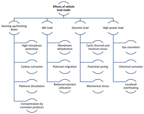
Figure 5.
Effects of the vehicle load mode overview.
Table 3.
Degradation effects due to vehicle loading regime [134,135,136,137,138].
3.1. Starting Up/Shutting Down
The startup and shutdown condition is completely atypical, resulting in abnormal FC reactions. This condition accelerates FC ageing due to interphase potential differences at the cathode, which can be as high as V, resulting from the air–hydrogen interface at the anode. The main skeleton of CL on the cathode is formed by a carbon carrier, which is strongly corroded as a result of these interphase potentials, and subsequently, Pt and ionomer catalysts are affected. There may also be changes in the structure of the cathode, and in extreme cases, it may disintegrate, adversely affecting the amount of ECSA, mass transfer, and charge transfer resistances. This leads to the need to develop materials capable of withstanding such high potentials (more than the range of the normal potential) and control strategies for turn-on/turn-off. A cold start, which is a special case of starting conditions, is mainly caused by freeze/thaw degradation [99,139,140,141].
3.2. Idle Load
In this scenario, the PEMFC system is in an idle state, operating without generating power. To maintain its normal function, the system runs on FCs at a low operating current density, typically around 8–10 mA· cm−2. The cathode is maintained at a high potential during this mode, close to the open circuit voltage (OCV). Operating under such conditions, especially at OCV, is commonly used to simulate idling, as it closely mirrors the impact on the FC’s lifespan. However, one of the challenges of this operating mode is membrane dehydration due to reduced water production. This condition can lead to significant CD membranes. Additionally, there is the issue of the migration and growth of platinum (Pt) particles, which is another concern under these operating conditions [44,56,142,143].
3.3. Dynamic Load
The actual power requirement of a vehicle often changes. This places a demand on the constantly changing FC loads. In particular, load variation is the hardest condition for the lifetime of PEMFCs. The load cycle in an FC is characterised by a cyclical variation in potential. Additionally, the amount of water produced electrochemically and the heat emitted from the FC fluctuate with variations in the load. This results in an internal environment marked by thermal and moisture cycling, which significantly hastens the ageing of the catalyst and the mechanical deterioration of various components. In cases of load variation, the FC experiences a transient fluctuation process, impacting several input parameters, such as the stoichiometric ratio of the feed gases, pressure, RH, and temperature. Fluctuations in the parameters cause degradation of the components, accelerating FC ageing [113,144,145,146].
3.4. High Power Load
During specific vehicle operating scenarios, like climbing or accelerating, the FC is subjected to brief periods of high-power operation. This transient phase is characterised by swift changes in electrode potential, variations in the stoichiometric ratio of provided gases, internal pressure and temperature fluctuations, and shifts in the water state. These conditions heighten the risk of gas shortages, water flooding, and localised overheating. Consequently, there is an accelerated membrane CD alongside a marked increase in the corrosion of the carbon support. This enhanced corrosion contributes to greater solubility and agglomeration of the Pt catalyst, as detailed in studies [147,148,149,150,151,152].
3.5. Summary of Effects of the Vehicle Load Mode Chapter
This section presents the significant impact of vehicle load modes on the DMs of PEMFCs, with each mode introducing specific stressors that accelerate component ageing and reduce system longevity. Startup/shutdown cycles induce high interphase potentials, leading to severe carbon corrosion and catalyst layer degradation. Idle load conditions, characterised by low current density and high potential, promote membrane dehydration and platinum particle migration, resulting in chemical degradation. Dynamic load variations exacerbate mechanical and thermal stress, accelerating wear on the catalyst and membrane. High-power loads further amplify degradation through localised overheating, gas starvation, and intensified chemical and carbon corrosion.
To address these challenges, strategies such as developing more durable materials, optimising operational protocols, and employing advanced control mechanisms are essential. Mitigating the degradation effects of varying load modes is critical for improving the durability and performance of PEMFCs, enabling their reliable use in automotive applications.
4. Fuel Cell System Degradation Modelling Methods
A degradation model aims to forecast the dynamic behaviour of a system under consideration, considering varying operational parameters and time in operation. It is essential that this model incorporate the aspect of performance degradation over time, influenced by changes in operating conditions. This is crucial because, without this consideration, diagnostic and prognostic algorithms may struggle to differentiate between abnormal working conditions and actual degradation. The model should effectively simulate dynamic responses, like output voltage, in relation to a range of inputs, including temperature, current, working time, pressures, and humidity. This model can be applied for diagnostics, prognostics, or energy management purposes.
Over the past decade, numerous studies have explored the mechanisms and behaviour modelling of FC and battery degradation. However, a limited focus has been on developing models that specifically characterise degradation laws. Approaches to modelling FC and battery systems generally fall into three categories: physics-based models, data-based models, and hybrid models that combine elements of both the previous types [153,154,155]. Modelling FCs degradation overview is illustrated in Figure 6.
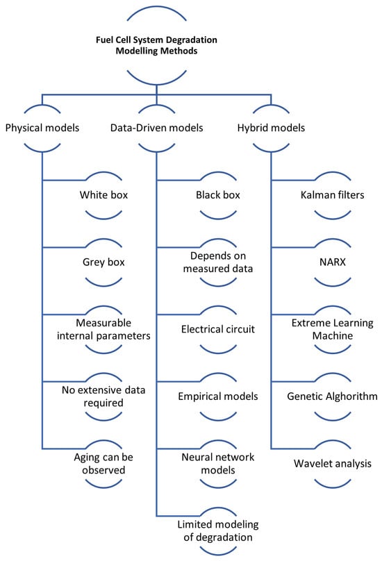
Figure 6.
Modelling fuel cell degradation overview.
Physical models: These models can be categorised as either white or grey box models. They are fundamentally rooted in physical equations. White models are mechanistic, meaning they strictly adhere to physical laws, whereas grey-box models are semi-mechanical or semi-empirical. Semi-empirical models primarily derive from the physical equations of the studied system but may include an empirical component, such as a resistance parameter.
The strength of physical models lies in their ability to generalise well without needing extensive data. As they are grounded in physical equations, these models allow for the observation and comparison of changes and the evolution of the system’s internal physical states and parameters. However, modelling membrane degradation using a physical model requires a deep understanding of the issues and poses several additional challenges [156]. They are computationally intensive due to the detailed descriptions of physical and chemical processes required, making simulations of entire FC stacks demanding despite simplifying assumptions [157]. A significant drawback is the difficulty in identifying and accurately determining many physical parameters, as they are often not directly measurable and must be estimated, introducing potential errors and uncertainties. This challenge is amplified by the nonlinear nature of PEMFC characteristics, which complicates precise parameter identification [158,159,160]. Additionally, these models are highly sensitive to operating conditions, such as temperature, pressure, and humidification, which can lead to inaccuracies if parameters are not appropriately adjusted, thereby reducing robustness and reliability under varying scenarios [157,161]. The problem of using these models to model dynamic conditions is used, for example, to model cold starts of a fuel cell [162] or to model transient phenomena [163]. Furthermore, to ensure computational feasibility, several simplifying assumptions are typically made, which can limit the accuracy and ability of the model to capture the real-world behaviour of PEMFCs. Particularly concerning aspects are membrane hydration and reactant partial pressures [157,164].
Data-driven models: These are typically black box models. They depend on the measured data for learning and modelling the system’s behaviour. This category includes electrical circuit, empirical, and neural network models. A key feature of data-driven models is that they do not necessitate knowledge of the system’s internal parameters or a thorough understanding of its degradation laws. However, this means they lack the ability to observe and link changes in the internal parameters of the PEMFC system, leading to a gap in crucial diagnostic and decision-making information. A significant drawback of these models is that they require a substantial amount of representative training data. Since degradation laws vary across systems, the ageing data must be sourced from similar types of systems, generalising these models is challenging [165].
The advantages of this modelling approach can be summarised as follows:
- Rapid and accurate predictions: data-driven models can provide quick and precise predictions based on historical data, which is crucial for real-time applications and decision-making processes [166].
- Nonlinearities capture: these models are adept at capturing the nonlinearities in degradation data, which is essential for accurately predicting the remaining useful life (RUL) of FCs [167].
- Reduced computational demand: compared with physics-based models, data-driven approaches generally require less computational power, making them more suitable for real-time applications [168].
- Flexibility and adaptability: data-driven models can be easily updated and retrained with new data, allowing them to adapt to changing conditions and new degradation patterns [169].
- Effective for complex systems: they are particularly useful when the degradation mechanisms are not fully understood, as they rely on empirical data rather than detailed physical models [170].
The disadvantages of using data-driven models are as follows:
- Data dependency: a significant drawback is the heavy reliance on large amounts of high-quality data, which can be difficult and expensive to obtain [170].
- Generalisation issues: these models may struggle to generalise effectively to new operating conditions or scenarios that were not represented in the training data, potentially leading to inaccurate predictions [166,171].
- Lack of physical insight: data-driven models do not provide insights into the underlying physical and chemical processes causing degradation, which can be a limitation for developing comprehensive understanding and mitigation strategies [166].
- Overfitting risk: there is a risk of overfitting, where the model performs well on training data but poorly on unseen data, reducing its reliability in practical applications [172].
- Complexity in model selection: choosing the appropriate model and tuning its parameters can be complex and time-consuming, requiring expertise in both the domain and machine learning techniques [173].
Hybrid models: these models are based on a combination of physics and data-based models.
Hybrid models use the strengths of both physics-based and data-driven approaches, leading to improved accuracy in degradation predictions. For example, combining wavelet analysis, Extreme Learning Machine (ELM), and Genetic Algorithm (GA) has been shown to outperform traditional methods [174] while integrating least square support vector machine (LSSVM) with regularised particle filters (RPF) effectively captures nonlinear degradation patterns [167]. These models also enable comprehensive analysis of both reversible and irreversible degradation processes; for instance, approaches using adaptive Kalman filters and NARX neural networks can predict detailed and overall degradation trends [175]. Furthermore, hybrid models enhance reliability by providing uncertainty characterisation for the remaining useful life (RUL) through probabilistic distributions [167]. Their dynamic adaptability to new data and changing operating conditions improves robustness and accuracy, as demonstrated by moving window-based prognostic methods that continuously update and refine predictions [173]. Additionally, hybrid models are effective in diagnosing and predicting multiple fault types, which is essential for complex systems like FCs. For instance, a novel hybrid model for steam-reforming solid oxide FC systems can track operational trends and address multifault degradation scenarios [176].
Hybrid models, despite their advantages, come with significant challenges. Their integration of multiple modelling techniques increases computational complexity, making them resource-intensive, as combining physics-based and data-driven methods often leads to higher computational demands [166]. They also require precise parameter tuning and are sensitive to parameter selection, complicating development and potentially affecting the robustness of predictions [166]. Additionally, these models depend heavily on historical data, which may limit their ability to generalise to new operating conditions or scenarios without sufficient data [166]. The development process is both costly and time-consuming, requiring extensive data collection, training, and validation. For instance, creating hybrid models that combine voltage and mechanism-based approaches necessitates complex and expensive characterisation data [177]. Moreover, implementing these models in real-time systems is particularly challenging due to their complexity; for example, the distributed model of a solid oxide FC in a hybrid configuration requires advanced control strategies to minimise degradation effects [178].
4.1. Modelling Fuel Cell (FC) Degradation Using a Physical Approach
This approach meticulously represents the intricate physical processes linked to degradation and formulates them through analytical equations. Research employing this method often concentrates exclusively on either catalyst or membrane degradation (MD). It is tailored and validated for specific operating conditions, encompassing factors like current density, dynamic or steady-state behaviour, temperature, and relative humidity (RH). However, one notable aspect of this approach is the high computational demand it may impose, particularly in cases where it involves solving additional transport equations.
4.2. Models Based on Membrane Degradation
The degradation of polymer electrolyte membranes in FCs can be categorised into three primary types:
- Mechanical degradation: this involves the physical damage to the polymer, resulting in the formation of pinholes and cracks.
- Chemical degradation (CD): this type focuses on the breakdown of the polymer chain, which occurs due to chemical reactions with hydrogen peroxide free radicals.
- Thermal degradation: this occurs at high temperatures (above 150 °C) and leads to the drying of the membrane and the decomposition of sulfonyl functional groups.
Singh et al. [154] developed a model for transient CD and applied it in the finite element method-based modelling software COMSOL Multiphysics 4.3a. The scope of this article is restricted to the CD of membranes and its impact on PEMFC performance. The 2D model utilised a dynamic mesh to represent membrane thinning accurately owing to hygrothermal swelling and material loss. The 2D formulation was considered for spatial changes in important variables like current density and concentration and provides a framework for coupling with working work on modelling mechanical degradation in which the membrane is affected by varying stresses between solid and porous regions. The effect of platinum in the membrane is not taken into account; however, an initial uniform concentration of iron (II) is taken into account, which works as a Fenton reagent in the membrane. The effect of degradation on the PEMFC steady-state performance and, conversely, the effect of OCV-hold on transient CD are addressed. The model contains two models for steady-state performance and transient CD; coupling is obtained by sharing time/degradation-dependent variables between modules. Eventually, the method is validated against experimental OCV stored test data for PEMFCs polarisation behaviour and CD. The current model builds on 1D models, extending the method to 2D and representing CD of membrane utilizing a multi-step kinetic model.
The model is composed of two macroscopic 2D isothermal sub-models:
- A steady-state performance model of PEMFC.
- A transient chemical MD model.
The 2D isothermal model for the CD of polymer membranes in PEMFCs is designed to simulate the process through two distinct stages: (1) the hydroxyl radical’s indirect formation and (2) a four-step attack by hydroxyl radicals that includes the terminal ether bond on the side chain, near the main chain ether bonding, cleavage of the side chain, and unzipping of the chain. The model, which operates at the level of the MEA, was validated based on its comparison with the polarisation behaviour observed in a five-cell assembly, both initially and after the assembly underwent degradation during a ten-hour open circuit voltage (OCV) hold test. The observations of fluoride emission rate, voltage drop, and changes in membrane thickness during the OCV hold test align qualitatively with rates of degradation recently reported in scientific literature.
In their research, Xie et al. [179] employed Nafion® ionomer with an equivalent weight (EW) of 1100 as a model for PFSA (perfluorinated sulfonic acid) ionomers. They developed a kinetic model aimed at uncovering the initial mechanisms behind the CD of PFSA in various environments, including those found in FCs. This model enables a quantitative analysis of how different degradation conditions, such as those present during FC operation, influence the degree of side chain cleavage in PFSA. The significance of this study lies primarily in two aspects: firstly, in validating or challenging the relevance of accelerated ex situ tests, and secondly, in offering insights for enhancing the durability of PFSA materials through the intentional molecular design of new PFSA compounds. The kinetic model formulated in this study serves as a versatile instrument for unravelling the chemical DMs of PFSA in diverse environments, including those found in FCs. This research’s true value and application will be fully recognized by expanding the kinetic model to encompass PFSA polymers subjected to various degradation scenarios, such as those encountered under various FC working conditions.
Wong et al. [180] created a one-dimensional (1D) macroscopic model for a membrane electrode assembly (MEA) that incorporates a detailed MD algorithm designed for the simulation of the macroscopic impacts of CD in the membrane in situ. This algorithm is grounded in empirical findings often overlooked or oversimplified in prior Proton Exchange Fuel Cell (PEFC) degradation models. This approach allows for comprehensive predictions regarding changes in the ionomer’s molecular structure and macroscopic properties, as well as the behaviour of hydrogen peroxide and hydroxyl radicals, in relation to the onset and progression of degradation.
The model’s predictions about the ionomer molecular structure have been compared with and validated against recent experimental data. Additionally, the numerical algorithms formulated in this model are intended to be compatible with contemporary MEA and FC computational models. This compatibility establishes a connection between macroscopic phenomena, in situ operational conditions, and membrane degradation.
The model is further utilised within a 1D MEA domain to simulate the macroscopic impacts of chemical MD, such as membrane thinning, release rates of fluoride ion, ionic resistance, and void stress, during PEFC accelerated stress tests (ASTs). The outcomes from these simulations are compared with experimental results, and the model’s overall capabilities are examined and discussed. The current modelling framework is based on the in situ CD of unreinforced PFSA ionomer membranes. The model for degradation presented in this research comprehensively encompasses the formation of radicals, the mechanisms of MD, and their impacts on the membrane’s physicochemical properties. However, it does not account for the degradation of ionomers in CLs, as our accelerated stress tests did not reveal any significant ionomer degradation in these areas. For degradation simulation under realistic FC conditions, this degradation model has been integrated with a 1D membrane electrode assembly (MEA) performance model.
The MEA model is designed to detail macroscopic transport phenomena primarily governed by mass-species conservation equations, typically characterised by a diffusion–reaction system. This set of equations is solved within a computational domain that includes the membrane, CL, and gas diffusion layers (GDL). The domain is further segmented into subdomains comprising the macroporous substrate and a microporous layer (MPL), with all MEA layers normalized by their thickness. The model considers three separate phases: the gas and solid phases within the GDL and CL and the ionomer phase within the CL and membrane. Additionally, the model schematic illustrates various species and transport phenomena incorporated into the simulation.
Shah et al. [181] have performed numerical simulations based on a model that is constructed in a hierarchical manner, starting from the simplest case of unrestricted metal-ion impurity supply and no side-chain cleavage. The numerical simulations provide predictions of H2O2, OH, and COOH formation rates, end-chain cleavage, side-chain cleavage, and HF formation. The evolution of these quantities with respect to time and changes in operating conditions is discussed. The observed trends are compared with experimental results, and the feasibility of a peroxide-based model of membrane CD and radical formation is assessed. To confirm the underlying phenomenology, parametric studies are performed on several unknown reaction constants.
Li et al. [182] developed a model for polarisation thickness degradation for a PEMFC based on experimental data and polarisation curves. This model focuses on evaluating the thickness of the PEM and how it varies with the ageing process of the PEMFC. In this context, the thickness of the PEM, along with the PEMFC current density and voltage, changes as the FC ages.
To construct this model, voltage and current density data from a PEMFC were gathered using a test rig under specific conditions. The researchers adapted a new semi-empirical model from traditional degradation models. This revised model represents voltage changes in relation to current density and PEM thickness. They also developed a reverse approach to separate the PEM thickness from the operating time in the voltage and current density context.
The relationship between the thickness of PEM and PEMFC working time is characterised as a rational fraction with a second-order numerator and a first-order denominator. In their proposed model, the mechanism of PEM thickness variation, represented as a rational fraction, is incorporated into the regenerated semi-empirical model. This allows for converting time-discrete polarisation curves into a time-continuous form that enables real-time approximation of the PEMFC’s State of Health (SoH).
The accuracy of this continuous polarisation curve model was validated based on its comparison with experimental time-discrete polarisation curves, demonstrating an accuracy of over . Karpenko-Jereb et al. [183] focused on (1) analysing existing theoretical methods utilised for modelling degradation phenomena in PEMFCs and forecasting their lifetime and (2) developing a semi-empirical model of polymer electrolyte MD that could be employed for 3D CFD analysis of the performance of PEMFC in the degraded condition.
The objective is to develop an innovative model for 3D CFD analysis of PEMFCs, focusing on the time-dependent degradation phenomena in the polymer electrolyte membrane. This new model is divided into two primary components: the first part is a semi-empirical model that calculates the temporal changes occurring in the membrane. This semi-empirical model accounts for how various working conditions, like RH, temperature, and voltage, influence the degradation rate.
The second component of the model is dedicated to evaluating PEMFC performance, utilising the CFD software AVL FIRE® (AVL FIRE 2024 R2). The data regarding membrane characteristics, as determined by the first model, are fed into the AVL FIRE 2024 R2® software. This integration allows for the simulation of FC performance at distinct moments. The theoretical framework underpinning the changes in PEM characteristics is grounded in data sourced from the scientific literature.
The developed model is able to forecast the time-dependent variations in the physicochemical characteristics of a perfluorinated Nafion membrane at the following working conditions: The model is developed for the case where there is a negligible gas pressure gradient across the membrane. In this condition, the oxygen and hydrogen transport across the membrane is just by diffusion due to the concentration gradient.
- Comprehensive inclusion of CD effects: the model includes the impacts of CD on various aspects of the membrane, such as the following:
- Thickness.
- Ionic conductivity.
- Concentration of acidic groups.
Additionally, it accounts for the cross-diffusion of gases like H2, (O2), and (N2). - Mathematical representation of DRs: DRs are mathematically represented as functions of variables, such as the following:
- Temperature.
- RH.
- Voltage across the cell.
- Link between DRs and oxygen transfer: the rates of degradation in membrane thickness and ionic conductivity are closely linked to the rate at which oxygen (O2) transfers across the membrane.
- Correlation between acidic groups and conductivity: there is a proportional relationship between the changes in the following:
- Concentration of acidic groups within the membrane.
- Relative reduction in its conductivity.
This correlation is established using percolation theory principles, typically applied to ion exchange materials. - Critical thickness and hole formation: the model posits that holes begin to form in the membrane when the following occurs:
- Thickness reduces to a critical level, denoted as .
- Significant increase in gas diffusion below critical threshold: when the membrane thickness diminishes further, going below the critical threshold (), the following occurs:
- A significant increase in gas diffusion.
- Indicating a marked escalation in MD.
The 3D CFD analysis of individual cell function at various operational times reveals that the reduction in acid group concentration and conductivity of the membrane is not uniform, and it is dependent on local working conditions. The degradation model is employed for the simulation of the cell current density evolution under a constant cell voltage () at various temperatures and RH levels. Increasing temperature and decreasing RH accelerate the concurrent decrease in density, aligning with observations in scientific literature.
In a study by Futter et al. [184], a comprehensive 2D model of the PEMFC was developed by integrating models for gas transport via the PEM, formation of electrochemical hydrogen peroxide, iron ion transport, electrochemical reactions, formation of the radical, structure of the polymer, and radical attack on the polymer. The simulated cell performance closely matches experimental results, achieved by fine-tuning only a few parameters, showcasing the performance model’s predictive capabilities. The model also considers non-ideal thermodynamic relationships for hydrogen peroxide in a two-phase system, prompting a re-evaluation of the reaction’s creation kinetics. Additionally, it explores an expanded set of chemical reactions that lead to hydroxyl radical formation, accounting for their temperature dependencies. Where data on the temperature dependence of the reaction kinetics are lacking, a sensitivity study has been carried out to highlight the significance of further research in this area. Literature values were used for the kinetics of the side-chain unpacking and cleavage mechanism where available. The link between membrane CD and the performance of FC is obtained by simulating membrane thinning and gas crossing. The model is validated against experimental data for fluoride emission rates. Experimental and simulated OCV evolution during accelerated stress testing (AST) is compared. There was acceptable agreement between experimental and simulated data. The important outputs of this study are as follows:
- In order to view the CD of the membrane in PEMFC, it is necessary to take into account the hydrogen peroxide’s high affinity for the liquid phase.
- CD is most distinct on the PEM anode side and is significantly dependent on voltage. The existence of iron ions, their corresponding (electro)chemical reactions, and their transport must be taken into account to explain these observations.
- For the simulation of operando CD, the temperature dependency of radical formation reactions must be considered. The impact of degradation reactions on the steady-state concentration of hydroxyl radicals must also be taken into account.
- There may be a considerable difference between the rate constants of degradation reactions in confined spaces within the membrane and the values determined from ex situ measurements of model compounds in an aqueous solution.
- CD of the membrane causes it to thin, which promotes the transfer of hydrogen from the anode to the cathode. This results in an increment in the internal short circuit current, reducing the OCV and, thus, the cell function.
- The decrease in OCV during AST cannot be explained by an increase in hydrogen cross-linking owing to membrane thinning alone. Further investigation of this phenomenon is needed.
- Degradation increments with working pressure owing to an increase in oxygen transverse transition and hydrogen peroxide’s subsequent formation.
- Humidification enhances CD of membranes by promoting gas crossing and reducing potential gradients, thereby enhancing ionic conductivity.
- In OCV, the CD of the membrane is most pronounced because the gradients in ionic potential are low, and iron ions are free to move. As the cell voltage decreases, the iron ions are pulled to the cathode side, and the CD of the membrane becomes milder.
Ehlinger et al. [153] introduced a comprehensive, transient model that simultaneously evaluates the performance and durability of an entire FC. This model integrates a microkinetic framework that addresses degradation due to gas transition and employs concentrated solution theory to explain transport processes in the PEM.
A key aspect of the transport model is its consideration of the interrelated electrochemical forces driving the movement of cerium ions, protons, and water. To enhance the membrane’s lifespan, cerium ions are incorporated into the membrane. These ions are effective in mitigating CD by neutralising radicals generated as reaction gases pass through the PEM. However, the introduction of cerium ions is a double-edged sword. While they significantly reduce CD during the operation of PEMFC, they can also diminish performance by altering membrane transport characteristics and potentially causing blockages in the CLs.
The model forecasts how the migration of cerium ions from the membrane to the CLs affects cell performance. It also contrasts dilute solution theory with concentrated solution theory to demonstrate how water management within the cell influences the distribution of cerium. Notably, higher RH conditions are found to promote more appropriate retention of cerium within the membrane.
An analysis of voltage loss indicates that cerium presence results in power reduction in the cell, primarily by reducing proton activity and changing the transport dynamics of protons and water across the membrane. According to the findings of transient simulations, the best balance between function and durability is achieved with lower concentrations of cerium in the membrane. The study also examined the impact of thicknesses of CL and membrane as design factors, concluding that higher membrane thickness and lower CL thickness are optimal for maximising both performance and durability.
4.3. Models Based on Catalyst Degradation
The long-term degradation of catalytic layers (CLs) encompasses various processes, including catalyst ageing, catalyst particle migration, catalytic material loss, dissolution of the electrolyte (Nafion ionomer), and carbon particle enlargement. These processes collectively lead to an apparent reduction in the CL’s activity and can be attributed to changes in the active surface area, leading to a loss of electrical and ionic connectivity or alterations in the catalyst’s microstructure. The primary mechanism responsible for catalyst degradation observed during accelerated stress testing (AST) is the decrease in the electrochemically active surface area (ECSA) of nanoparticles, which occurs due to a combination of reprecipitation, dissolution, and particle coalescence processes [185,186].
In the study reported by Kregar et al. [187], the model’s main objective is to provide a high level of prediction of the entire FC system from the input in the form of FC operating and control factors to the FC operating conditions determining the individual DMs and Pt DRs at the cathode by modelling the redistribution of the size of Pt in the transient working regime. This needs an innovative combination of various phenomena in the nanoscale driven by transient degradation stimuli obtained by the design of FC and working conditions.
Thus, the needs of the FC operational model could be summarised as mechanically based, transient, spatially resolved, and fast in terms of computation. Conversely, the needs in the degradation modelling framework can be summarised as based on (the most influential) individual DMs, capable of considering (the most effective) interactions between various individual DMs, transient and fast in terms of computation.
The basic framework of the physically based spatially and temporally resolved HT PEMFC traffic model is a new computationally efficient method that combines two-dimensional (2D) analytical and one-dimensional (1D) numerical solutions, referred to as hybrid 3D analytical-numerical (HAN). Thus, the real-time capable HAN approach enables, on the one hand, the achievement of high levels of prediction in FC function modelling, which are important for sufficient virtual FC integration into the model, and, on the other hand, the provision of spatially and temporally resolved degradation stimulus data, which are essential input factors for the degradation modelling system.
This approach ensures that the degradation model can respond reasonably to variations in design and control parameters, ensuring a consistent representation of degradation dynamics within the FC. To enhance computational efficiency, the model introduced here utilises a discrete particle size distribution that is uniformly applied to all pertinent DMs. The proper handling of this distribution of particle size is essential for the accurate treatment of these two mechanisms.
Models for the oxidation reactions of platinum and carbon include a Kelvin term that deals with surface tension, which is dependent on the size of the particle, and a determination of the Pt particle removal rate by considering both carbon corrosion electrochemical kinetics and the size of the particle.
The model in question offers a comprehensive approach to simulating the degradation phenomena that affect the catalyst over the FC’s operational lifetime. It achieves this by continuously modelling the evolving particle size distribution, adhering strictly to the principles of conservation laws. This approach is not limited to catalysts made purely of platinum (Pt); it can also be adapted for binary catalysts, albeit with appropriately adjusted DRs.
However, it is crucial to note that this model does not account for certain DMs unique to binary catalysts, such as the dissolution of individual components and leaching from the particles. As for the degradation of the membrane, the model does not directly simulate this aspect. Instead, it incorporates the impact of MD on the catalyst’s deterioration by considering gradual changes in membrane thickness and variations in ionic conductivity within the FC’s operational framework. This allows for an indirect yet significant consideration of MD in the overall modelling of the FC’s performance and longevity. It is crucial to indicate that the proposed model is designed for system-level simulation over a longer time period. Careful attention has been paid to balancing the detail and computational cost levels to adequately model and replicate the most important function and degradation phenomena and their interactions to meet these model requirements. Therefore, an important contribution of the research is that it presents a system-level mechanistic modelling principle for degradation and performance modelling that takes FC system-level modelling to a new level. The presented model allows—in comparison to the state of the art—to explore the design space not only with respect to FC performance but also in terms of FC lifetime.
In the study by Li et al. [188], a carbon corrosion model and an agglomerate model in the CL are combined for forecasting the CL performance during startup and shutdown cycles. Both models were validated against experimental data from the literature. Moreover, a parametric study was represented for analysis of the impact of operating conditions (e.g., pressure, RH, and the highest and lowest stresses) and structural factors (e.g., platinum loading, carbon loading, and ionomer fraction) in the agglomerate model on initial function and voltage degradation rate (VDR) at a different number of cycles.
An analytical model has been developed to forecast the performance deterioration of the cathode CL during startup and shutdown cycles. This model utilises the carbon corrosion model, making assumptions that both platinum loading and void volume decrease in proportion to the loss of carbon loading to determine changes in structural parameters. The electrochemically active surface area (ECSA) is determined by establishing a relationship between the radius and the platinum radius. Subsequently, the structural parameters and ECSA output are employed in the sinter model to anticipate CL performance following a given number of cycles. The model’s outcomes align closely with experimental data. Following model validation, a parametric study explores the impact of various operational and structural parameters, including RH, pressure, maximum and minimum cyclic stress, carbon amount, platinum amount, and ionomer fraction within the agglomerate. Based on this investigation, the following conclusions can be drawn:
- Enhancing the gas pressure can boost the performance of the catalyst layer (CL) and diminish the voltage degradation rate (VDR) due to the heightened concentration of oxygen supply. For effective operation, it is crucial to maintain an appropriate relative humidity (RH) level. Notably, a higher maximum voltage and a lower minimum cyclic load voltage are associated with increased performance degradation.
- Starting with a low carbon content and a high platinum content in the CL can lead to better initial performance and generally result in a lower VDR. However, this effect becomes marginal when the carbon content drops below 0.4 mg·cm−2 and the platinum content exceeds 0.2 mg·cm−2.
- Through this established computational model, the forecast of CL performance degradation during startup and shutdown cycles, as well as parameters for optimal CL design, can be achieved.
The research conducted by Jia et al. [189] focuses on incorporating the Electrochemical Active Area (ECA) function into a three-dimensional model of a PEMFC. Their study aims to compare the numerical outcomes of this model with experimental data and utilize the validated model to explore the underlying mechanisms of the PEMFC.
In their modelling approach, only the cathode side of the cell is simulated. This is due to the significantly slower oxygen reduction reaction (ORR) at the cathode than the hydrogen oxidation reaction (HOR) occurring at the anode. The model’s geometry is structured in a bottom-up manner, consisting of four layers: the bipolar plates at the bottom, followed by the cathode GDL, the cathode CL, and finally, the polymer electrolyte membrane at the top.
The model calculates velocity and pressure fields using the Navier–Stokes equations. It also integrates the transport equations with two potential equations, representing the solid and membrane phases. The properties at the interfaces between these layers are designed to be continuous. The outer boundaries of the model are set as isolated, with the potentials assumed to be zero.
For the development of this model, the programming is carried out using the SIMPLE algorithm, and the codes are written in FORTRAN 95, a programming language known for its efficiency in handling scientific and numerical computations. Kneer et al. [190] investigated the effect of stress cycling in a hydrogen/air atmosphere on catalyst degradation to simulate automotive operating conditions. Stress factors included lower and upper potential limits, inlet gas RH, temperature, and upper potential limit (UPL) residence time. These selected values are intended to represent specific operating conditions in automotive applications and are available at the FC or powertrain system level. Temperature, humidity, and upper and lower potential limits were selected as stress factors. The effect of residence time in the UPL on degradation is also noted. This effect was addressed in a previous study using the same membrane electrode arrays (MEA) as used in this study. A semi-empirical ECSA loss model was derived from the acquired AST data and fitted to an analytical polarisation curve model to estimate the MEA performance after voltage cycling. In previous studies, experiments related to voltage cycling were performed using the same MEA as in this.
Declining ECSA during AST was fitted to a first-order kinetic rate model, and each stressor’s degradation rate was determined. A linear dependence of the DR on humidity and residence time in the UPL was demonstrated. An exponential variation in DR was observed for temperature and Arrhenius-type upper potential limit. The lower potential limit had only a small effect on degradation compared with other stressors. A semi-empirical ECSA loss model was subsequently derived and validated from the measured data. The model enabled the estimation of electrochemically active surface area (ECSA) loss for various voltage cycles with a deviation of less than . Using the estimated ECSA, the polarisation curve after degradation was simulated and compared with the measured data. Consequently, the performance of degraded membrane electrode assemblies (MEAs) could be accurately predicted, particularly up to a current density of , through simple electrochemical characterization of MEAs at the beginning of life (BOL). This approach is valid when the primary DMs involve platinum dissolution and platinum particle growth.
Zheng et al. developed an extensive model to comprehensively address the degradation of platinum (Pt) within membrane electrode assemblies (MEAs). Their primary objective was to investigate the evolution of Pt distribution within MEAs and explore strategies to mitigate the loss of Pt Electrochemically Active Surface Area (ECSA). The model encompasses the governing equations and mechanisms governing Pt degradation in the CL as well as Pt precipitation in the Polymer Electrolyte Membrane (PEM).
The study includes comparing simulation results under various working conditions with experimental data. The research delves into the significance of Pt mass loss (ML) and the Ostwald ripening mechanism regarding ECSA loss. Additionally, the investigation focuses on mitigation strategies to address ECSA loss.
The model’s validation involves comparing its predictions against experimental data from symmetric triangular wave and rectangular wave potential cycles. This validation process verifies the model’s ability to predict behaviour under dynamic operating conditions.
The study identifies that the Pt ML mechanism primarily occurs near the interface between the PEM and CL. In contrast, the Ostwald ripening mechanism exhibits a uniform distribution and is suppressed near the PEM/CL interface due to the more prominent Pt ML. Furthermore, the significance of the Ostwald ripening mechanism increases with more frequent potential cycling. As the upper working potential increments, the Pt ML mechanism would be more critical and dominate Ostwald ripening. Consequently, mitigating the Pt ML mechanism is crucial for enhancing the durability of the Pt catalyst, particularly at high cell voltages.
The research explores strategies for mitigating ECSA loss by suppressing Pt ML. It introduces a composite membrane structure reinforced with expanded polytetrafluoroethylene (e-PTFE) and featuring graded structural properties. The findings revealed that this graded PEM architecture, which includes the anodic backing layer, lower gas diffusivity, higher content of e-PTFE in the support layer, and higher gas diffusivity in the cathodic backing layer, can reduce ECSA loss by shifting the Pt band position away from the CL cathode. Furthermore, decreasing the diffusivity of Pt2+ ions within the MEA effectively suppresses the transport of Pt2+ ions to the Pt band, significantly reducing ECSA loss. This mitigation strategy proves particularly effective when the Pt ML mechanism primarily drives ECSA loss. Jahromi et al. [191] presented a new experimental algorithm to predict the loss of catalyst CL performance during cyclic loading. The algorithm was composed of two models, known as Models 1 and 2. Model 1 determines the electrochemical surface area (ECSA) and agglomerate size (e.g., the radius of agglomerate, rt, agg) for the CL under cyclic loading. Model 2 is an existing model from studies conducted earlier by this author that calculates the catalyst’s performance with fixed structural factors. The combination of Models 1 and 2 predicts the performance of the CL under arbitrary cyclic loading at various RHs and cell temperatures. The algorithm’s (combination of Models 1 and 2) accuracy is evaluated against extensive experimental data. A group of parametric/sensitive studies is implemented to assess the impacts of working factors on the VDR percentage, with a rating of 1 for the most influential. The parameters considered include temperature, pressure, RH, and maximum and minimum cyclic load voltage; the findings revealed that temperature and pressure have the greatest and least effect on VDR %, respectively. An elevation in temperature from to resulted in more than a increase in VDR, while a decrease in VDR of was achieved by incrementing the pressure from 2 atm to 4 atm.
In a study conducted by Jahromi et al. [192], a semi-transient simulation approach was developed to integrate a novel degradation model with a complete 3D CFD model for forecasting the performance of PEMFC subjected to potential cycling. The degradation model focuses on capturing structural changes in the cathode CL, including factors like electrochemically active surface area (ECSA) loss, Pt particle growth via Ostwald ripening, and dissolution of Pt in the ionomer in the process of potential cycling. These factors are then utilised in the CFD model to predict power loss.
The 3D-CFD model calculates PEMFC performance by solving conservation equations for mass, species transport, momentum, energy, liquid water saturation, electric and proton charge, and dissolved water content in the ionomer. This integration of a novel degradation model predicting CCL structural changes with a comprehensive 3D-CFD simulation for PEMFC performance prediction represents a significant advancement in research to assess PEMFC performance degradation under vehicle load cycling.
The study introduces a novel aspect by proposing a multi-objective optimization approach with four different scenarios. This optimisation aims to identify the optimal values for operational and structural parameters to minimise degradation in the process of potential cycling and maximise initial power output. This innovative optimisation problem is a unique contribution to the research, making it the second novelty of the work. The research employs a three-dimensional (3D) simulation to forecast performance degradation in PEMFCs due to potential cycling, a critical load condition in the automotive industry. Subsequently, an optimisation problem is formulated and solved to minimise performance degradation over the FC’s lifetime while maximizing practical performance.
A 3D and CFD model is shown that simulates the operation of a PEMFC and predicts its function during load cycling. In this work, an FC with a single PEM is considered a solution domain that contains a polymer exchange membrane (PEM), anode and cathode catalyst layers (ACL, CCL), GDLs, gas channels (CH), and bipolar plates (CC). The governing equations are composed of eight transport equations: (i) mass, (ii) momentum, (iii) species, (iv) energy, (v) electric charges, (vi) protonic charges, (vii) liquid water saturation level, and (viii) dissolved water in the ionomer phase. The Ansys 2024 R1® software package was used to solve the mentioned equations.
Zhang et al. [193] studied complex reactive transport processes in nanoscale CL architectures and evaluated the impacts of Pt degradation on cell function at the pore scale. The porous architectures of degraded and original CLs were regenerated, so the detailed distributions of carbon, Pt, ionomer, and pores before and after degradation are solved. This pore-scale physicochemical model addresses oxygen dissolution at the pore/ionomer interface and electrochemical reactions at reactive sites. The impacts of Pt DR, reaction rate, Pt loading, and Pt particle distribution on reactive transport processes at the pore scale were also investigated. To account for the effect of CL degradation, a multiscale simulation strategy was developed to extend the results obtained at the pore scale to cellular-scale models. Finally, important conclusions based on pore and multi-level studies were drawn.
Numerical simulations were performed at the pore scale to determine the effect of Pt degradation on reactive transport processes in CL PEMFC. Using our own reconstruction algorithm, the reconstruction of the CL structure at the nanoscale was performed for subsequent simulations at the pore scale using our own reconstruction algorithm. With a resolution of up to 2 nm, which is the common size of Pt particles, the details of the distribution of carbon, Pt, pores, and electrolytes are resolved with a resolution of up to 2 nm; this corresponds to the typical size of Pt particles. Results from the Pt particle size distribution experiment for new and degraded CLs were considered for the regenerated CL structures.
Furthermore, a physicochemical model for reactive oxygen transport inside the CL was presented. This model considers oxygen dissolution at the secondary pore–ionomer interface, oxygen diffusion within the ionomer phase, and electrochemical oxygen reaction at the interface of ionomer–Pt. Based on the lattice Boltzmann method (LBM), a related pore-scale numerical approach is also developed.
Then, the pore-scale model is used to investigate the reactive transport processes inside the reconstructed CL architectures with various distributions of Pt particle size indicating various degradation levels. The effect of Pt degradation on Pt utilisation, ECSA loss, overall reaction rate, and resistance to local gas transport is assessed. It was observed that Pt degradation leads to a decrease in Pt recovery and loss of ECSA by up to . Due to the loss of ECSA, the overall reaction rate (or current density) is also reduced, resulting in higher transport resistance. The impacts of Pt degradation at various Pt loadings and Pt distributions are also investigated, and three important conclusions are provided. First, the impacts of Pt degradation would be stronger under lower Da (the relative strength between the diffusion process and the chemical reaction), which is due to the longer diffusion length of oxygen before its depletion. At low Da, the reaction proceeds with more Pt particles, resulting in ECSA loss of a greater role. Second, similar to the previous result, the larger participation of Pt particles in the reaction at low Pt loading leads to more damage due to catalyst degradation. Third, the larger amount of Pt distributed in the inner agglomerate causes the oxygen path to lengthen and the Pt degradation effect to be greater.
The study introduces a multiscale simulation approach aimed at bridging the gap between pore-level analysis and the PEMFC model. Pore-level simulations are employed to generate a dataset of bulk current density under varying overpotential and oxygen concentration conditions. This bulk current density data are subsequently integrated into the cell-scale model as source terms.
To illustrate the effectiveness of this multiscale simulation strategy, the researchers combine a continuum-scale 1D model for the CL with pore-scale models. This integrated approach successfully captures the adverse effects of platinum (Pt) degradation on cell performance, as demonstrated by the polarisation curve. It is important to understand the effect of Pt degradation on cell function and to design optimised architectures and working conditions to reduce Pt degradation. Although the Pt degradation mechanism is a complex process, the most common manifestation caused by Pt degradation is the loss of ECSA. The pore size simulation in this study confirms that resistance to gas transport increases with Pt degradation, and the pore structure and phase distribution significantly affect the degree of power loss owing to Pt degradation. The power loss is more pronounced at low Pt loading, and appropriate Pt distribution effectively reduces Pt degradation. The degradation of Pt is closely related to the process of reactive transport inside the CL since reactive transport processes degrade Pt, but at the same time, the structural and electrochemical alteration of the CL arose from the degradation changes in the transport and reaction processes. This study uses the architectures of pristine and degraded CL structures as input for subsequent pore-scale reactive transport studies.
Koltsova et al. [194] have developed a model that includes the main mechanisms of platinum catalyst degradation: electrochemical dissolution of platinum nanoparticles, particle growth owing to Ostwald ripening, particle migration over the carbon support, fusion of dispersed fine particles into larger units, diffusion of platinum ions in the ionomer, and their transfer to the membrane. Based on the mathematical model, it is possible to achieve the particle size distribution, platinum ion concentration distribution as a function of time, and active layer thickness. The lifetime of the FC can be predicted from the time dependence of ECSA. The results of the simulation show that the growth rate of platinum particles of the commercial catalyst is almost two times higher than that of the catalyst synthesised on CNT. This again demonstrates the great stability of catalytic systems fabricated using nanotubes compared with those synthesised commercially on carbon black.
Ao et al. [153] have developed a degradation model for PEMFC based on the Pt particle transformation theory. This model establishes a system comprising a number of Pt particles to simulate the degradation process of the PEMFC catalyst. These particles undergo molecular changes one by one, following predetermined transformation mechanisms, specifically the dissolution of Pt and Ostwald ripening mechanisms.
After degradation, the model calculates each particle’s molecular number and radius within the system. This information is used to derive the particle radius distribution and the system’s Electrochemically Active Surface Area (ECSA), which is a critical parameter for assessing the PEMFC’s condition.
The key contributions of this research are as follows:
- Introduction of a novel model for PEMFC degradation based on the catalyst transformation theory, accounting for both Pt dissolution and Ostwald ripening mechanisms. This model enables the determination of Pt particle size changes during operation, providing insights into the catalyst’s health status.
- Validation of the proposed model for PEMFC catalyst degradation using six sets of experimental data. The model’s calculations closely match experimental results for particle radius distributions and electrochemical surface area (ECSA).
- Comparison with traditional analytical models, demonstrating that the provided PEMFC catalyst degradation model offers higher accuracy. It encompasses more catalyst degradation mechanisms (DMs), enhancing its precision.
- Presentation of a method for applying the generated model for PEMFC catalyst degradation to predict long-term degradation in PEMFCs. This capability makes the model valuable for forecasting degradation and the overall lifespan of PEMFCs.
This article explains the proposed model of PEMFC catalyst degradation in detail. Furthermore, the model’s results are verified by the data obtained in the experiments and compared with another model to demonstrate its advantages and reliability.
- The novel PEMFC degradation model effectively simulates the Pt catalyst degradation in PEMFCs. Its application to six experimental cases demonstrates a strong correspondence between the model’s predictions of particle radius distribution and ECSA and the experimental results, affirming its reliability.
- Compared with the analytical model mentioned in the reference, the developed PEMFC catalyst degradation model delivers superior accuracy. This improvement is attributed to the incorporation of both Pt dissolution and Ostwald ripening mechanisms, aligning the model more closely with real-world conditions.
- This study establishes a foundational framework for exploring the Pt transformation process within PEMFC catalysts. With further research on the degradation of Pt catalysts, additional precise mechanisms can be readily integrated into this model, enhancing the clarity and accuracy of describing the PEMFC degradation process.
Karpenko-Jereb et al. [195] consider three degradation mechanisms of Pt/C catalyst: dissolution and oxidation of Pt, as well as diffusion of Pt ions in the membrane. However, we neglect the particle size growth. In this way, Pt ML, particle size reduction, and the lifetime of the Pt catalyst, which is reduced by these three degradation processes, are monitored. The considered CL model has about 30 input parameters representing the working conditions of the PEMFC. The aim is to assess their influence on the output of the degradation model, which could be quantified by the rate of Pt ML during the cycling of the electric potential. Indeed, less platinum loss will lead to a longer catalyst lifetime: when the Pt mass drops to zero, the FC no longer works. In terms of statistics, a global sensitivity analysis studies the simultaneous impact of multiple input factors on the variance output. It could be explained by Sobol sensitivity indices usually approximated using Monte Carlo methods. Local sensitivity analysis, commonly referred to as the one-variable-at-a-time (OAT) method, examines how changes in one parameter impact the output. The Pearson correlation coefficient is a reasonable choice for sensitivity index assessment when dealing with nearly linear dependencies. Given the presence of many input factors, we opt for the latter approach.
The local sensitivity analysis is conducted across various cycle scales, including 10, 100, and 1000 cycles, to evaluate the correlation between platinum ML and several key parameters. These parameters encompass temperature, ionomer volume fraction, Pt loading, pH, particle diameter, and diffusion. For the sensitivity analysis, these variable parameters’ upper and lower bounds are selected based on their physical properties and values obtained from relevant literature. This parameter variation leads to approximately a reduction in the initial mass of Pt ions, which is suitable for local analysis. Further investigation is required to explore the interplay between operational conditions and these parameters.
The physical model is constructed based on the following set of assumptions:
- The model considers a semi-infinite cathode catalytic layer (CL) within a PEMFC situated between the gas diffusion layer (GDL) and the membrane.
- Within the CL, spherical platinum (Pt) nanoparticles are embedded onto a carbon support, and they are completely enveloped by a perfluorinated sulfonated ionomer.
- The same ionomer fills all gaps and spaces within the GDL and the PEM.
- Two distinct degradation mechanisms (DMs) are responsible for the dissolution of Pt ions into the surrounding environment and the creation of platinum oxides on the catalyst particles’ surface.
- Pt ions have the capacity to diffuse through the ionomer and into the PEM but not into the GDL.
- All observed parameters and properties exhibit variations along a single dimension across the CL while they remain constant in the other directions.
To comprehensively assess the degradation status across different spatial dimensions, it is essential to integrate this 1D model with a 3D performance model commonly employed in CFD simulations. In doing so, all the necessary working conditions for the Pt degradation model must be considered locally. It is important to note that local operating conditions are strongly influenced by the specific design of the FC.
It can be hypothesised that at the inlet where O2 or air is introduced, the DR of Pt tends to be higher due to elevated temperatures and increased O2 concentration. As per the model, Pt degradation will be accelerated in areas characterised by higher water concentrations and elevated temperatures. The simulation results presented here indicate that higher temperatures lead to a faster ML of Pt, increased acidity mitigates the dissolution of Pt, and a higher ionomer ratio slightly expedites Pt degradation. Additionally, it is worth noting that the ML of Pt is significantly affected by the size of Pt particles, with smaller particles experiencing higher dissolution rates attributable to Gibbs–Thomson energy considerations.
4.4. Summary of Fuel Cell System Degradation Modelling Methods Chapter
This section explores methods for modelling FC system degradation, focusing on physical, data-driven, and hybrid approaches. Physical models offer detailed insights but are computationally intensive, while data-driven models provide quick predictions but rely on extensive data and lack physical understanding. Though they remain complex, hybrid models balance these strengths, combining accuracy with adaptability. A comparison of the models in terms of computational complexity, prediction accuracy, and applicable scenarios can be seen in Table 4.
Table 4.
Comparison of physical, data-driven, and hybrid models for PEMFCs degradation [166,196,197,198,199].
Advancements in modelling degradation for key components like membranes and catalyst layers enable better predictions of performance loss and structural changes. The choice of model depends on the application, with hybrid approaches offering the most promise for balancing performance and durability.
5. Equivalent Circuit Models (ECM) and Atomistic and Molecular Modelling of Degradation
An overview of equivalent circuit models and atomistic and molecular modelling of degradation chapter is shown in Figure 7.

Figure 7.
Modelling fuel cell degradation overview.
5.1. Principles and Structure of ECM in PEM Fuel Cell Diagnostics
Equivalent circuit models represent the electrochemical processes in a fuel cell by means of an electrical circuit composed of ideal elements (resistors, capacitors, inductances, or special elements such as a Warburg element). The goal of ECM is to approximate the dynamic voltage–current behaviour of the cell, for example, to model voltage losses due to ohmic resistance of the membrane, activation polarisation at the electrodes, and transport constraints, using a combination of resistors and capacitances. A typical ECM for a PEMFC may include a series ohmic resistor (membrane, electrolyte) and a parallel RC cell representing the double-layer capacitance and activation resistance on the catalyst; alternatively, an additional parallel cell or Warburg impedance element is added for diffusive (mass) transport in the electrode. For example, the Nyquist impedance diagram of a PEMFC often exhibits a high-frequency arc associated with charge transfer and a low-frequency arc associated with transport phenomena [200]. In some cases, however, the centre frequency arc may be associated with other processes, such as diffusion impedance or pseudocapacitance phenomena. This corresponds to an ECM with two RC circuits (for activation and transport) and a series resistor. The advantage of the ECM is its simplicity and the rapid identification of parameters from measurements (e.g., electrochemical impedance spectroscopy, EIS), which is valuable for real-time diagnosis of the fuel cell condition. Thus, ECM finds application in onboard vehicle diagnostic systems, which infer the cell’s internal state from measured electrical quantities.
5.2. Use of ECM in Degradation Monitoring
Equivalent circuit parameters can be considered as indicators of fuel cell degradation. As the cell ages, the ohmic resistance of the membrane typically increases (due to loss of membrane conductivity or drying), and the activation resistance at the cathode also increases (due to loss of active Pt catalyst area) [201].
Conversely, the bilayer capacitance decreases, reflecting the electrochemically active electrode surface area decrease due to the dissolution and agglomeration of Pt particles. The decrease in bilayer capacity is related not only to the dissolution and agglomeration of Pt particles but also to their redistribution or “coarsening” (particle enlargement). This phenomenon leads to a reduction in the number of active sites for the oxygen reaction. In addition, contamination of the catalyst (e.g., adsorption of impurities on the Pt surface) may also contribute to the decrease in .
EIS can quantify these changes; for example, catalyst degradation is reflected by a 30% increase in polarisation resistance and a concomitant decrease in diffusion impedance [202]. There are cases where the diffusion impedance may not always decrease. In some cases, it may increase due to degradation of the microporous structures in the electrode or impaired membrane hydration that affects gas diffusion. Kim et al. [203] proposed to monitor the state of the cell online just through the ECM parameters obtained from EIS—they used an equivalent circuit with four different resistances characterising the different degradation phenomena and showed that their evolution over time correlates with the decrease in cell performance [201]. In this way, lifetime prediction can be performed: changes in ECM parameters during accelerated load cycles allow prediction of the remaining useful life (RUL) of a PEMFC in real operation [204]. In automotive applications, where the fuel cell is subject to frequent start–stop cycles and dynamic loading, such diagnostics are particularly important—they allow early detection of deterioration (e.g., increased membrane resistance due to drying or degradation) and corrective action (humidification control, limitation of stressful operating modes, etc.). In addition to the aforementioned increase in membrane resistance upon drying, chemical degradation of the membrane (e.g., attack of OH- radicals on the membrane) can also occur, causing permanent damage. Preventive measures include not only humidification control but also optimisation of operating conditions, e.g., limiting operation at extreme current densities or faster shutdown under hazardous conditions.
5.3. Comparison of ECM with Physically Based Models
The ECM is a simplified (semi-empirical) description of fuel cell behaviour, whereas physically based models are based on detailed descriptions of transport phenomena, electrochemical reactions, and material properties. The main advantages of ECM are its computational simplicity and ease of identification of circuit parameters, which can be determined from experimental data. Then, the cell voltage response can be quickly simulated. In contrast, mechanistic models (e.g., distributed models of gas flow, proton and electron transport in electrodes, water formation, etc.) solve systems of partial differential equations and provide a more detailed picture of the processes inside the cell (concentration profile, current density in the electrode, etc.). These models are more accurate when extrapolated to different conditions but at the cost of high complexity and the need for many input parameters. For example, a purely electrical model using an ECM captures only the electrochemical impedance of the cell but neglects the explicit influence of the reaction gases and their dynamics, which is essential for PEMFC [204]. Static equivalent circuits (RC or RL cell) can reproduce the basic shape of the polarisation curve but fail to capture the hysteresis during load changes or the influence of non-current states. In contrast, dynamic physical models can incorporate compressor inertia and pressure and humidity changes, thus explaining phenomena such as voltage hysteresis during load cycling [204]. These models often incorporate multiple areas of physics, such as thermodynamics, fluid mechanics and electrochemical kinetics, to accurately describe the behaviour of PEMFCs under realistic conditions.
Therefore, combining both approaches is often desirable: the ECM can be used for online diagnostics and control, while detailed physical models can be used for system design and analysis of specific degradation scenarios. Current trends are also towards the use of machine learning together with ECM neural networks trained on EIS data to help automatically classify failure modes (flooding, drying) better than a static equivalent circuit [205]. A major challenge remains linking the ECM to physical meaning: even if a change in a particular resistance in the ECM indicates degradation, its exact physical cause (e.g., loss of catalytic activity vs. corrosion of the carbon substrate) may not be unambiguously determined without a supporting physical model or experiment [204].
5.4. Atomistic and Molecular Modelling of Degradation and Use of Density Functional Theory (DFT) in the Study of Catalyst Degradation
Density functional theory (DFT) allows the study of reactions on the catalyst surface at the atomic level by calculating the electronic structure of materials. In the context of PEMFC, DFT has been widely used to study platinum catalyst degradation at the cathode, in particular the mechanism of Pt dissolution and the loss of active area during operation. It is experimentally known that potential cycling (e.g., during start/stop cycling in an automobile) leads to the gradual oxidation of the Pt surface and the subsequent dissolution of Pt2+ into the electrolyte, which is the main cause of the reduction in the electrochemically active surface area (ECSA) of the catalyst. DFT calculations support these phenomena and provide detailed insight into the elementary steps; for example, a recent study with DFT at constant potential showed that at >1.1 V vs. RHE, a two-dimensional oxide layer composed of PtO4 units forms on the Pt(111) surface, which has a character similar to that of Pt3O4 [206]. In practice, however, the oxidation of Pt can proceed in several steps, and at even higher potentials (>1.5 V relative to RHE), PtO2 can be formed, which is even more stable and can inhibit further electrochemical reactions.
For completeness, it should be mentioned that the species of Pt oxides also depend on the crystallographic orientation of the surface—e.g., the oxidation behaviour of Pt(111), Pt(100), and Pt(110) may differ. Upon subsequent cathodic polarisation, these PtO4 units are reduced to form [PtOH(H2O)3]+ complexes soluble in the electrolyte. As a result, Pt atoms are stripped from the surface in the form of Pt2+ aqua complexes, resulting in Pt depletion at the electrode. In this way, DFT revealed a specific atomistic mechanism for Pt dissolution: for example, the cathodic dissolution reaction Pt3O4 + 8H+ + 6e− → [Pt(H2O)4]2+ + 2 Pt (decomposition of the oxide layer with the release of one Pt2+ complex and the redeposition of two Pt atoms on the surface) has been proposed. In addition to the dissolution of Pt, DFT can be used to study other degradation processes in the catalytic layer—e.g., the binding of Pt to the carbon support and the mechanism of particle detachment during carbon corrosion or the calculation of diffusion barriers for Ostwald ripening (the transfer of Pt atoms from smaller to larger particles). DFT also helps in the search for more resistant catalysts: calculations of adsorption energies and dissolution potentials for different Pt alloys (PtCo, PtNi, etc.) allow us to predict which composition will be less prone to oxidation and dissolution and thus more stable in long-term operation. The challenge of DFT approaches remains the reproduction of realistic conditions in a fuel cell—standard DFT calculates the system at 0 K and in the absence of liquid, but advances such as the inclusion of solvent effects (e.g., periodic water models or polarisation continuum) and simulations at constant electric potential bring the calculation conditions closer to reality. This atomistic information is valuable for macroscopic modelling: the DFT provides reaction parameters (thermodynamic and kinetic data) that can be fed into larger models—e.g., the dissolution rate constants of Pt for a model of catalyst degradation over time or the diffusivity of Pt in a layer for a model of Ostwald ripening. Thus, we can include plausible mechanisms in macroscopic simulations with DFT, increasing the predictive power of catalyst lifetime models [206].
5.5. Molecular Dynamics and Membrane Degradation Simulations
Molecular dynamics (MD) is a computer simulation that tracks the motion of atoms and molecules over time according to the classical forces acting between them. MD is mainly used for PEM fuel cells to study polymer membranes (typically Nafion or similar perfluorosulfonic acid membranes) at the molecular level. MD simulates the nanoscopic structure of a hydrated membrane, the formation of water clusters in ion channels, the mobility of protons (H3O+) and water through the channel network, or the interaction of sulfonic groups with the polymer chain. This information is key to understanding membrane degradation, which occurs chemically (chain scission by radicals) and mechanically (material fatigue due to pressure and swelling). MD simulations can directly model the mechanical stresses on the membrane; for example, by applying tension to a simulated volume of the polymer, the elastic modulus and strength can be estimated, and how these properties change when the polymer structure is disturbed. Studies have shown that degradation of Nafion (caused by radical cleavage of the main chain or side chains) leads to a reduction in inter-polymer entanglement and thus a deterioration in mechanical parameters—in an accelerated test corresponding to 24 h of chemical stress, Nafion’s Young’s modulus decreased by 6.5%. The cause is the shortening of the polymer chains and loss of bonds -OH type radicals can attack weak spots at the ends of the chains, triggering “unzipping” of the main chain (gradual cleavage of monomer units from the end) [207]. In practice, random chain scission is also often observed, leading to a sudden drop in molecular weight and mechanical strength of the membrane.
At the same time, Nafion side chains are cleaved by radical attack on the ether bonds—this releases fragments (fluorinated radicals, HF, CO2) that terminate the conducting side chain by forming non-conducting end groups [207]. MD simulations (especially when combined with quantum calculations or reactive potentials such as ReaxFF) can mimic these elementary processes and estimate the energy barriers to the reactions. Since direct simulation of chemical degradation would far exceed the time capabilities of MD (degradation takes place over hundreds of hours of operation, and MD typically simulates nanoseconds), shortened periods with high radical concentrations are used to accelerate the processes, or MD and kinetic models are combined. For example, radical reactions in Nafion have been investigated using so-called metadynamics or umbrella sampling over MD trajectories to derive the most likely pathways for bond cleavage and formation of intermediates [180,208].
Another area where MD has provided valuable insights is the contamination of the membrane by ions from the environment. If metal cations (e.g., Na+ and Ca2+ from the water supply or the surrounding environment) enter the membrane, they can exchange places with protons on the sulfonic groups and reduce the proton conductivity. MD studies have quantitatively shown that the presence of these foreign cations significantly reduces the diffusional mobility of protons (H3O+) and water in the membrane—e.g., for Na+ and Ca2+, a decrease in the diffusion coefficient of both water and protons was observed, with divalent Ca2+ having an even stronger negative effect than monovalent Na+ [209]. This is consistent with experiments where membrane contamination causes an increase in the ohmic resistance of the cell. In addition to transport properties, contamination also affects membrane mechanics: simulations and measurements suggest that larger cations can act as “crosslinkers” between sulfone groups and slightly increase the elastic modulus, but if chemical degradation subsequently occurs (e.g., by Fenton’s reagent in the presence of NaCl), the effect of chain shortening takes over, and the modulus drops significantly [207]. MD thus helps to isolate the individual effects of pure ion exchange vs. actual polymer cleavage on the resulting membrane properties.
5.6. Relationship Between Atomistic Simulations and Macroscopic PEMFC Models
Atomistic and molecular modelling offer microscopic insight into degradation mechanisms that can be used to improve macroscopic models of fuel cell ageing. DFT calculations provide information such as the activation energies of Pt dissolution reactions, the stability of different surface oxides, or the binding energies of Pt atoms to support. This information can serve as input to the parameters of degradation models within a large-scale fuel cell performance and lifetime model. For example, the catalyst dissolution rate can be formulated in the macro model according to the Arrhenius equation with parameters obtained from DFT (which increases the physical accuracy compared with a purely empirical approach). Similarly, MD simulations of the membrane provide transport coefficients (proton diffusivities, water) and mechanical properties (modulus, strength) as a function of degradation rate, which can be used in the continuum models of PEMFC. An example is a multi-stage model where the MD is used to determine the decrease in Nafion proton conductivity at a certain level of Ca2+ contamination, and this relationship is introduced into a macroscopic simulation of cell performance; thus, the model better predicts the increase in internal resistance of the cell when operating in a loaded environment [209]. Another contribution of atomistic simulations is the discovery of new degradation pathways, which can then be incorporated into macroscopic considerations. For example, DFT studies have proposed alternative mechanisms for membrane chemical degradation in the presence of H2 (the so-called H3O radical mechanism) [210], which has led developers to consider these pathways in models in addition to the classical Fenton mechanism. However, fully integrating different scales, from quantum chemistry to molecular dynamics to the whole fuel cell, is still challenging. Multiscale modelling of PEMFC degradation struggles with temporal and spatial scale differences: atomistic simulations cover nanometers and nanoseconds. At the same time, a real cell degrades on the scale of centimetres and thousands of hours. Therefore, current approaches combine submodels: DFT/MD results are simplified into effective parameters or trends inserted into simpler macromodels (called parameter upscaling). There is also a trend to use machine learning to accelerate this coupling by training, e.g., neural networks on data from MD simulations and experiments; simplified predictors of material behaviour can be obtained and fed into system models.
For automotive and energy applications of PEMFCs, such an integrated view is essential: it allows us to account for how microscopic changes (dissolution of individual Pt atoms, breaking of covalent bonds in the polymer) will affect the macroscopic performance and lifetime of the entire fuel module. The challenge for the future is to refine these models further, refine the DFT description of the system containing the liquid and electrode potential, extend MD simulations to larger time scales using dilute models, and develop validated multiscale models predicting degradation under different operating profiles. Successfully meeting these challenges will contribute to the design of more robust fuel cells that meet the long lifetime requirements of both transportation (on the order of 5000 h of operation) and power (more about 60,000 h for stationary sources) [204].
5.7. Summary of the ECM and Atomistic and Molecular Modelling of Degradation Chapter
PEM fuel cell degradation modelling has progressed from simple equivalent circuits to detailed atomistic simulations. Equivalent circuit models have proven to be a practical tool for cell health monitoring and failure prediction—allowing inference of ongoing degradation processes based on changes in electrical parameters. On the other hand, DFT and MD simulations reveal the molecular nature of these degradation processes, such as dissolution of the Pt catalyst, oxide formation, polymer cleavage, or the influence of impurities. The combination of both approaches results in multilevel models that can diagnose the cell’s current state and predict its evolution under a selected load cycle. Current trends include the integration of online diagnostics in control systems (important for fuel cell vehicles) and using advanced simulations to design degradation-resistant materials (e.g., stabilised catalysts and reinforced membranes). The main benefit of modelling is the ability to accelerate the development of longer-life PEMFC systems. The models can be used to test “virtually” different operating scenarios and material improvements without requiring lengthy experiments for each case. However, the challenge remains to validate and calibrate these models against good experimental data to ensure reliable predictions. Continued research in this area combining electrical, chemical, and materials approaches is the key to making fuel cells an economically and operationally viable technology for mass deployment in transport and energy [206].
6. Modelling of PEM Fuel Cell Degradation from Measured Data
The data-driven approach learns the ageing trend of the FC and uses the FC operating data to establish an FC degradation model. The modelling approach based on measured data is suitable when physical models are inaccurate or too complex to implement. These models are typically built using algorithms trained on large-scale experimental data [175]. Most data-based methods build a degradation model for PEMFCs without considering the effects of changes in PEMFC working conditions. These working conditions, which have a significant influence on PEMFC degradation, include changes in load current, temperature, RH, and hydrogen pressure. Artificial intelligence (Al), statistical, and signal processing models are used to do this. These can be further subdivided; see Figure 8 [211].
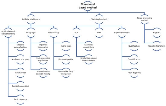
Figure 8.
Non-model-based method overview [211].
Artificial intelligence can be divided into three types: artificial neural network (ANN), fuzzy logic (FL), and neuro-fuzzy (NF).
An artificial neural network (ANN) can be conceptualised as an abstract computational model inspired by the human brain. Much like the brain, an ANN is comprised of artificial neurones that act as processing units, and it features extensive interconnections among these neurones. What sets an ANN apart is its remarkable capacity to learn from provided examples and generalise its knowledge. In other words, it can generate meaningful outputs for new input data that it has not encountered during its learning phase. The key characteristics of an ANN include its ability to learn from examples, generalise effectively, process information nonlinearly, adapt to varying situations, support extensive parallel connections among processing units, and exhibit fault tolerance [212].
Fuzzy logic (FL) is an approach that simplifies complex decision-making by allowing for the sensible use of imperfect information. It can be applied through hardware, software, or a combination of both. Essentially, fuzzy logic in problem control mimics human decision-making but with much faster processing capabilities.
The methods used for analysis and controlling with fuzzy logic can be summarised as follows:
- Gathering one or multiple assessments or measurements of conditions within a system to be analysed or controlled.
- Processing all collected inputs based on human-generated fuzzy “if-then” rules, which are expressed in simple language and can be combined with traditional non-fuzzy processing.
- Aggregating and weighing the outcomes of individual rules to produce a single output decision or signal that guides the actions or instructs the controlled system. The resulting output signal represents the precise defuzzified value [213].
Neuro-fuzzy (NF) systems, on the other hand, combine the strengths of fuzzy logic and neural networks, making them a potent hybrid tool. These systems enable the incorporation of human expertise into the system and are considered more interpretable because they employ human-like fuzzy inference [214].
In this article, Ma et al. [155] used a Long Short-Term Memory (LSTM) network, which is a kind of RNN (recurrent neural network) that achieves state-of-the-art results in challenging forecasting problems. Deep learning approaches such as LSTM can be applied to forecast time series problems for both short and long periods. In comparison with the traditional RNN, LSTM is able to avoid the problems of gradient explosion and gradient fading, which can make short-term memory last for a long time period. The ageing of the FC over thousands of hours of operation makes LSTM a suitable approach to predict degradation. The simple architecture also makes it easy to apply LSTM to online diagnostic control, which could enable the design and validation of FC system control approaches. In this article, an innovative data-driven deep learning model for PEMFC degradation forecasting based on the LSTM network is proposed. In addition, based on the conventional LSTM network, the article proposes a Grid LSTM (G-LSTM) structure to further enhance prediction precision. The model is then validated by experimental results of ageing tests on three different kinds of PEMFCs under eight different working conditions.
The operational duration spans hundreds to tens of thousands of hours, during which all experimental ageing data are meticulously recorded to assess the FC’s performance.
To enhance the prediction of FC degradation, an extended deep learning approach is employed, building upon the foundation of a conventional RNN. An LSTM cell is incorporated into the network to mitigate issues like gradient fading and explosion.
Moreover, a specialised Grid LSTM architecture is devised and integrated into the LSTM model to predict FC degradation. The associated training algorithm is tailored to forecast the degradation of various FCs within a unified framework. The effectiveness of this advanced deep learning model, known as G-LSTM RNN, is substantiated through validation with experimentally acquired degradation data.
The model forecasting outcomes are verified using eight various load profiles from eight different FCs (three kinds). Meanwhile, various degradation models, namely the NAR network, RVM, and Elman network, are compared with the proposed G LSTM model. The conclusion can be drawn as follows: The findings suggest that the Gated Long Short-Term Memory (G-LSTM) model, as proposed, can consistently achieve impressive prediction accuracy across various FC operating conditions. For voltage prediction, it demonstrated a Root Mean Square Error (RMSE) of 0.0040 and a Mean Absolute Percentage Error (MAPE) of 0.0013.
Additionally, the model excels in tracking significant output variations, offering enhanced performance and reliability when compared with existing models, especially when the training data exhibits minimal variations.
This performance evaluation conducted with different sliding window sizes can serve as a valuable reference for establishing training criteria for a data-driven FC ageing model.
The proposed data-driven approach could fit various degradation FCs into the same training principle.
The model can predict FCs’ lifetimes and could also help monitor their operational performance in real-world applications, including FC electric vehicles and FC power systems.
In their research, Yang et al. [172] introduced an approach known as M-ANN (Multivariate Polynomial Regression (MPR) and ANN) to simulate the short-term degradation patterns observed in a PEMFC. Initially, they attempted to predict PEMFC degradation using only an ANN, but the results fell short of expectations. Recognising that both the initial state and the evolution of PEMFC performance vary across different operational conditions, they sought to enhance accuracy by separately predicting these factors using MPR and an ANN. Previous studies have suggested that combining different algorithms could yield superior results. Consequently, they proposed the M-ANN approach, which employs MPR to forecast the initial state under various conditions and utilises an ANN to forecast time-dependent performance changes. The workflow of the M-ANN method, as applied to forecast the degradation process of PEMFCs in dead-ended anode (DEA) mode, is depicted in Figure 9. To validate the model, they employed a verified physical model for the simulation of the degradation characteristics of PEMFCs in DEA modes, using anode recirculation and simulation data as substitutes for experimental data. Additionally, they discussed the potential for incorporating experimental data into this modelling.
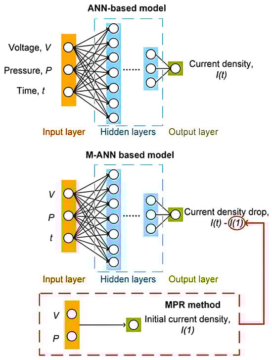
Figure 9.
Structure of ANN- and M-ANN-based models for estimating the PEMFC’s degradation process in DEA mode [172].
The results highlight that the predictive performance of the Multi-Parameter Artificial Neural Network (M-ANN) surpasses that of both the standalone artificial neural network (ANN) and Multi-Parameter Regression (MPR) when used individually.
Firstly, MPR effectively addresses the challenge of predicting initial values across various operating conditions, a task that is challenging for an ANN due to the limited sample size. On the other hand, an ANN excels at predicting the variation in cell power during the degradation process, a task in which MPR falls short.
Furthermore, exploring the impact of the number of hidden layers in M-ANN revealed that having two hidden layers yields superior performance compared with just one hidden layer. Additionally, the study compared the influences of various activation functions, specifically ReLU (rectified linear units) and sigmoid, on the M-ANN predictive performance. While neither function exhibited a significant advantage in terms of error, the curves generated utilising the sigmoid activation function were smoother, providing a more realistic prediction curve.
In summary, the M-ANN model demonstrates excellent predictive capabilities in both scenarios, demonstrating its versatility in capturing short-term degradation or dynamic behaviour in PEMFCs.
In this study, Legala et al. [215] applied artificial neural networks (ANNs) and support vector machine regressor (SVR) as machine learning approaches in order to propose data-driven models for the function attributes and internal states of the PEMFC. The working conditions of the PEMFC, like temperature, cell current, reactant pressure, and humidity, are utilised as input variables, while the output factors include the forecasted membrane resistance, voltage, and level of membrane hydration for various working conditions. The precision of the proposed data-based models is assessed, particularly under extreme conditions. The data utilised for this modelling study are obtained from (i) a semi-empirical physics-based model and (ii) a dimensionally reduced 1D CFD model, which was validated by experimental data. A total of 1100 data points were generated for each dataset, covering the full range of operations of PEMFC. A total of of the data points were utilised for learning, while the remaining of the data points were utilised for validation/testing. It is shown that an ANN clearly represents an advantage over SVR, especially when regressing the output with multiple variables. It is advantageous to model simple regressions using SVR because it significantly decreases the computation level without sacrificing precision. It is also evident that machine learning approaches incorporating dropout techniques can lead to highly precise predictions with for all forecasted factors, showing the ability to build precise models based rarely on data from validated physical models and reducing the dependence on large-scale experiments. This study suggests that other vector properties like interfacial resistance between layers, electrochemical impedance, ageing, and catalyst leaching, like water flooding, reactant deficiency, membrane mechanics, health status, and remaining useful life status, can be considered for better diagnosis and prediction of PEMFC performance.
Han et al. [216] performed a three-step procedure in this study. First, a test bed was developed to validate the proposed FC model and degradation model with the use of data obtained in experiments. The durability test was performed for 300 h with the NEDC (New European Driving Cycle) profile. Furthermore, a degradation model was developed for forecasting the cell current densities and durability over time. Thirdly, an integrated FC vehicle model was developed for simulation of the ageing FC model for evaluating the function of beam durability in driving cycles like UDDS (Urban Dynamometer Driving Schedule), HWFET (Highway Fuel Economy Test Cycle), and US06 (high acceleration aggressive driving schedule).
The ageing model created in this research can forecast the DR as a function of time (in hours) and current densities. To validate the ageing model, a simplified durability test bench was employed, and its performance was compared with the data obtained from experiments.
Furthermore, the developed FC ageing model was integrated into the vehicle model to anticipate the DR under different driving cycles, which included the UDDS, HWFET, and US06 cycles. This integration allowed the model to capture the transient responses related to vehicle speed, FC power requirements, and the water content in the fuel cell vehicle (FCV) during various driving cycles. Consequently, the study successfully accounted for dynamic behaviour in its analysis.
Vichard et al. [217] introduced an approach for modelling the degradation of an FC system, aiming to estimate its remaining lifespan. Their methodology began with a comprehensive long-term life test spanning 5000 h. This test was conducted to observe the function changes in a complete open cathode FC system under realistic transport conditions, including start/stop cycles and varying ambient temperatures. Subsequently, they analysed the test results to gain insights into the performance evolution.
The analysis revealed that ambient temperature played a significant role in both short-term and long-term performance changes. Lower ambient temperatures created more favourable humidification conditions. Notably, they reduced the DR. This system demonstrated high reliability for its intended application, with a mean DR of operating hours and a performance loss of only compared with its initial state. It is worth noting that these experimental results surpassed the target durability set by the US Department of Energy (DOE) for automotive applications.
On the basis of these analyses, the authors outlined a method for modelling performance evolution utilising echo state neural networks. This modelling approach took into account the impacts of working time and varying operating conditions. They elaborated on the network’s structure, parameters, learning scheme, and the selected inputs used in their modelling process. Finally, the measured data were utilised to develop a neural network-based degradation model. The results reveal that the proposed prediction tool is very suitable, as the forecast of degradation is very precise, with a prediction time of over 2000 h regardless of the ambient temperature and computation times of around 2 s.
Maleki et al. [218] modelled the rate of change at the cathode using an ANN. The backpropagation (BP) algorithm was applied for training the network, and data from experiments were utilised for training and testing of the network. In this study, two different models are constructed. First, potential cycles, humidity, and temperature are applied as inputs to forecast the resulting Pt dissolution rate at the cathode as the network output. Then, the dissolution rate of Pt and the diffusivity of Pt ions are taken as inputs to obtain the values of the rate of change in Pt particle radius, the rate of Pt ML, and the rate of surface area loss as outputs. The networks are fine-tuned, and the modelling results agree well with the data obtained from the experiment. The modelled ANN responses are acceptable for this intention. The BP algorithm was applied to train the network, and the experimental data were applied for training and testing the network.
Kim et al. [219] conducted a study exploring a diagnostic approach based on pattern recognition utilising a Hamming neural network. The objective of this approach was to identify suitable model parameters for diagnosing the state of health (SOH) of PEMFCs. To achieve this, they measured the output voltage patterns of 20 PEMFCs and collected model parameters as representative patterns.
By subjecting the FCOV patterns from the 20 individual cells to statistical analysis, they employed a Hamming neural network to identify the representative FCOV pattern that best matched the pattern of any cell being examined. In the context of the FC equivalent circuit model, the goal was to select a representative loss referred to as ΔRd, which is defined as the sum of two losses (concentration and activation losses).
Hissel et al. [220] proposed the use of fuzzy clustering for the diagnosis of the PEMFC system. The authors generated a PEMFC durability diagnosis approach based on fuzzy k-means clustering. Two kinds of experiments, steady-state operation and actual transport load cycle, are conducted on 100 W FC cells for 1000 h. The first step is to extract the elements that could mainly represent the ageing of the stack. According to the existing knowledge, two features are considered: the difference between internal and polarisation resistance and the highest absolute value of the Nyquist plot phase. Afterwards, the fuzzy clustering algorithm is implemented on the 2D feature space to form three clusters; each of them relates to a particular FC stack behaviour, called “young”, “middle age”, and “old”.
Mo et al. [221] have addressed the modelling of PEMFC using NF. The developed model has been used to introduce a fuzzy controller to control the output voltage of the PEMFC.
Placca et al. [222] demonstrated the utility of the Principal Component Analysis (PCA) approach in examining correlations between variables and similarities among measurements taken at particular sampling times. To complement this approach, they put forward an empirical model for a PEMFC. This model establishes relationships between various input parameters and the cell voltage through the application of multiple linear regression.
In the article authored by Riascos et al. [223], they introduce a monitoring system designed for diagnosing various types of faults that may occur during the operation of a PEMFC. This diagnostic system relies on the utilisation of Bayesian networks, which enable the qualification and quantification of the cause-and-effect relationships among different process variables.
The process of fault diagnosis is centred around the real-time monitoring of variables that are readily measurable within the FC system, including parameters such as voltage, electric current, and temperature. Notably, this FC system has the capability to continue operating even in the presence of a fault condition.
The assessment of fault effects is based on empirical data obtained from experiments conducted on a fault-tolerant FC. These experimental findings are subsequently incorporated into an FC model. To expedite fault diagnosis and mitigate the risk of permanent damage to the device, the authors establish a database of fault records derived from the FC model.
Jemei et al. [224] are concerned with modelling PEMFCs based on model-based neural networks. The proposed model is implemented in Matlab/Simulink R2024b® software and integrated into a complete vehicle powertrain. Thus, developing and simulating control laws to control the energy transfer onboard FC vehicles is possible. In this study, a static model of the FC system has been developed. Only four experimental learning patterns were required for the training phase of the network.
Chang et al. [225] present a study focused on the precise prediction of the output voltage generated by a PEMFC. They achieve this by integrating the genetic algorithm neural network (GANN) model with the Taguchi method. To accomplish this, experimental data obtained from performance tests conducted on a PEMFC were utilised to train and establish the GANN model for predicting the steady-state output voltage of the PEMFC. Additionally, the Taguchi method was employed to optimise the key parameters within the GANN model, with the objective of minimising the estimation error.
Chávez-Ramírez et al. [226] discuss the modelling of the NUVERA 5 kW stack, which has been developed using an ANN as an alternative approach to modelling an FC system when the relationship of the physical variables is not well understood. The ANN proposed in this work represents remarkable accuracy in modelling and forecasting for this particular 5 kW output; given the dimensional space of seven inputs and two outputs, the highest error calculated from each output factor was in the prediction of the stack voltage and from the output cathode temperature. Certainty and robustness were obtained by introducing noise into the data of experiments.
In the research conducted by Vural et al. [227], they employed an adaptive neuro-fuzzy inference system (ANFIS) to forecast the performance, including current and voltage curves, of a PEMFC under various operating conditions. The process involved training the ANFIS using a dataset of input and output data, followed by testing the trained model with an independent set of data from experiments. Finally, the trained and tested model was utilised to forecast the PEMFC performance curve under different operating conditions.
Xie et al. [228] introduced an innovative technique for predicting the degradation of PEMFC using the Adaptive Variational Modal Decomposition (AVMD) and Deep Belief Network (DBN) algorithm. The AVMD-DBN method presents several novel aspects:
- A novel framework for fusion prediction is proposed, combining the AVMD algorithm with a new cost function and multi-objective optimisation for a more efficient analysis of degradation characteristics.
- Sample entropy (SE) theory and clustering algorithms are integrated for preprocessing of the original data, enhancing degradation characteristics.
- Fusion prediction results from DBN models corresponding to partial signals exhibit greater reliability and accuracy compared with single DBN models.
- Due to the high nonlinearity and randomness of the degradation voltage time series, the AVMD approach is employed to decompose the voltage sequence into distinct sub-signals, effectively reducing data noise and enhancing features.
- The DBN approach, known for its robust feature extraction capabilities, is used to construct prediction models for each voltage sub-sequence, further improving prediction accuracy.
Experimental validation of the provided AVMD-DBN forecasting model using real PEMFC degradation data demonstrates high accuracy and reliability across various prediction horizons. This approach effectively extracts information related to FC ageing characteristics, ensuring the dependable operation of PEMFC systems.
Liu et al. [219] developed a precise online short-term prognostic approach for helping users extend their lifetime and decrease the cost of PEMFC. First, the short-term forecasting precision and computational efficiency of various methods, namely the Elman neural network, ensemble data processing approach, and ANFIS, were compared with different strategies for creating a fuzzy inference system and wavelet decomposition. The test results show that the ANFIS strategy with fuzzy c-means (ANFIS-FCM) has the best short-term forecasting performance. Afterwards, a method was proposed to adjust the parameters for ANFIS-FCM automatically using the particle swarm optimisation (PSO) algorithm. The test results revealed that the PSO algorithm can properly regulate the parameters and reach better prediction performance. Finally, the proposed prognostic approaches are verified on the PEMFC experimental platform. The experimental results represent that the proposed approaches have significant potential for practical intentions.
Changzhi et al. [229] present a novel hybrid data-driven framework designed to address time scale disparities among components and the voltage recovery phenomenon observed in PEMFCs. In this study, the approach draws inspiration from recent research on wind speed prediction [221] and battery capacity estimation [222], which employ signal decomposition techniques. In the initial phase, the PEMFC ageing data are segmented into multiple sequences to capture various time scales of component ageing. Subsequently, each decomposed sequence is further divided into linear and nonlinear segments, representing the overall declining trend and local renewal phenomena within each ageing time scale. These two types of sequences are then subjected to prediction using both linear time series methods and nonlinear machine learning approaches, resulting in enhanced prediction accuracy. In addition, an attention mechanism is introduced in the machine learning approach to enhance the prediction exactness of nonlinear information. To obtain the resulting prediction, the predictions of individual ageing periods are summed. The hybrid framework method introduced in this study incorporates several innovations:
- Adaptability to data: The proposed data-driven hybrid framework exhibits high adaptability to PEMFC data. It decomposes the PEMFC data into various time scales, further dividing each time scale into linear and nonlinear information segments. Specific prediction methods are then applied to these segments, enhancing overall predictive performance.
- CEEMDAN decomposition: The Full Ensemble Empirical Mode Decomposition with Adaptive Noise (CEEMDAN) approach is employed for the decomposition of the ageing trends present at different time scales within the raw FC ageing data. CEEMDAN facilitates independent forecasting and analysis of each ageing time scale, contributing to the accuracy of the predictions.
- GRU with attention mechanism: To enhance the prediction efficiency for nonlinear trends, the hybrid framework employs the Gated Recurrent Unit (GRU) approach with an attention mechanism. This approach is particularly effective in modelling and predicting nonlinear trends in the data.
Summary of Modelling of PEM Fuel Cell Degradation from Measured Data Chapter
Data-driven modelling methods are powerful tools for predicting and understanding PEMFC degradation. Techniques like an ANN, a LSTM network, and ANFIS effectively capture complex, nonlinear, and dynamic degradation behaviours. Hybrid approaches and optimisation strategies, such as CEEMDAN decomposition and attention mechanisms, enhance the accuracy and reliability of these predictions by addressing multiscale trends and nonlinear phenomena.
These methods provide precise forecasts for degradation trends and enable real-time monitoring and diagnostics, helping optimise PEMFC performance under varying operating conditions. By integrating operational data, these models can extend FCs’ functional lifespan, making them invaluable for practical applications, including electric vehicles and power systems.
7. Hybrid Models
Hybrid models aim to gain from the strengths of physical and data-driven models, as shown in Figure 10, an overview of possible hybrid models. However, the disadvantages can be combined, which causes certain limitations. Therefore, in order to preserve the advantages, it is necessary to reach a certain compromise and, ideally, to reduce the disadvantages. Hybrid models make it possible to reproduce early life behaviour (without degradation) without the need for large amounts of data, and in parallel, a machine learning tool could be run online for learning and prediction of performance losses throughout the system’s lifetime [50].
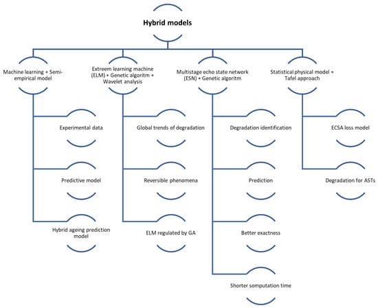
Figure 10.
Hybrid model overview [211].
In their paper, Wang et al. [230] introduced a novel approach that combines the strengths of machine learning techniques with a semi-empirical model to forecast the performance degradation of a PEMFC. This PEMFC was operated under semi-stable conditions for a duration of 931 h. Subsequently, they developed a semi-empirical model grounded in the DMs of PEMFC, utilising experimental data. Additionally, a sliding window machine learning model was employed to create a predictive model. To leverage the advantages of both models, they constructed a hybrid degradation prediction model, as illustrated in Figure 11.
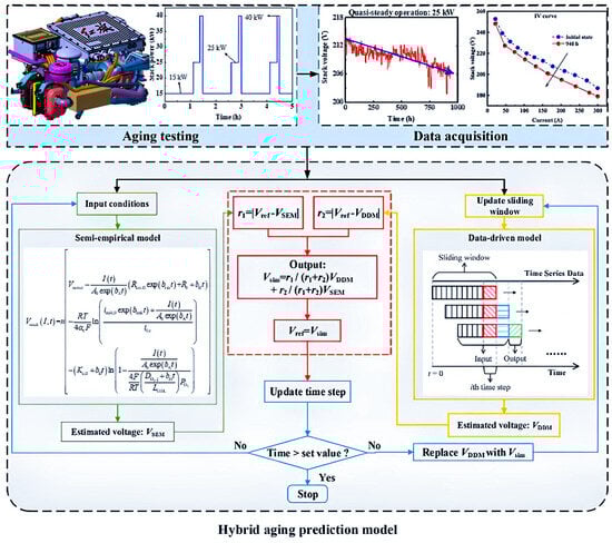
Figure 11.
Structure diagram of the hybrid prediction model of PEMFC degradation [230].
Figure 11 illustrates a hybrid ageing prediction model for PEMFC, which integrates a semi-empirical model with a data-driven model. The framework is designed to predict performance degradation over time by leveraging experimental data and simulations to estimate system behaviour.
The process begins with ageing testing, where experimental data are acquired under various operational conditions. These data include load profiles (e.g., power outputs of 25 kW and 40 kW), temporal performance decline during quasi-steady-state operation, and polarisation curves of the FC. These datasets are subsequently processed during the data acquisition stage, where time-series inputs are analysed using a sliding window approach to predict future system behaviour.
The model incorporates two principal computational methodologies: the semi-empirical model and the data-driven model. The semi-empirical model utilises physical principles and equations to estimate the system’s behaviour, with the estimated voltage () being calculated based on parameters such as current (I), resistance (R), and concentration. Conversely, the data-driven model relies on historical patterns in the time-series data to estimate voltage ().
The outputs from these two models are combined to generate a hybrid voltage estimate (), with weighting factors ( and ) determining the contribution of each model. The final voltage () serves as the predicted system output. The model iterates through regular time steps, updating its predictions until the simulation time exceeds a pre-set threshold, at which point the simulation concludes.
The lifetime of the PEMFC system was tested in semi-stable operation for 931 h. In order to forecast the performance degradation of the PEMFC, a data-driven model (DDM) and a semi-empirical model (SEM) are developed. Afterwards, the long-term and short-term degradation processes of both approaches are studied. A hybrid predictive model is further proposed according to the characteristics of both models. The most important findings of this work are outlined as follows:
The findings show that DDM outperforms SEM in short-term extrapolated prediction. As the extrapolated forecast lengthens, the accuracy of DDM will decrease; however, the SEM exactness will remain stable. In the case of a longer extrapolated prediction, the SEM would be more reliable.
The developed hybrid forecasting model represents a combination of the advantages of semi-empirical and data-driven models in a real-time adaptive correction process. The finding demonstrates that the hybrid model is able to enhance the prediction results oscillation of the data-driven model. In the long-term prediction process, it has the minimum RSME (0.8144) and the maximum R2 (0.8258) among the considered cases.
Chen et al. [174] introduced a hybrid approach for characterising the degradation patterns of PEMFCs tested under real driving conditions in FC electric vehicles (FCEVs). This innovative method combines the strengths of Extreme Learning Machine (ELM), Genetic Algorithm (GA), and wavelet analysis to account for the impact of working conditions on PEMFC degradation. Wavelet analysis plays a crucial role by decomposing the PEMFC stress-ageing waveform into multiple sub-waveforms, enabling the analysis of various degradation phenomena to improve the degradation model’s exactness. ELM is employed to propose the degradation model, and GA is utilised for the automatic adjustment of model parameters:
- The PEMFC degradation model was proposed and validated utilising data from three PEMFCs in three FCEVs that perform mail delivery.
- The developed hybrid model takes into account the effect of key variables that can cause performance degradation of PEMFC, including RH, load current, temperature, and pressure of hydrogen.
- The developed hybrid model combines wavelet analysis, ELM, and GA. There are two principal functions for the mentioned combination. First, wavelet analysis can be applied to the analysis of the global trend of degradation and reversible phenomena. Second, the parameters of the model based on ELM are automatically regulated and optimised by the GA.
The utilisation of GAs and wavelet analysis has proven to be highly effective in enhancing the accuracy of the degradation model for PEMFCs in fuel cell electric vehicles (FCEVs) under real-world conditions. Among the various approaches examined, the WGA-ELM-Sig approach stands out as the most accurate degradation model for PEMFCs in FCEVs. This underscores the importance of considering PEMFC loading current, RH, temperature, and hydrogen pressure, as they exert a substantial impact on the accuracy of the degradation model on the basis of the proposed WGA-ELM-Sig method in real-world PEMFCs operating within FCEVs. Importantly, the computational time required by the WGA-ELM-Sig method is remarkably short when compared withto the prediction time for PEMFC degradation in FCEVs under realistic conditions. Consequently, this method can offer early predictions of PEMFC degradation. Furthermore, the fact that the maximum absolute percentage error remains below 3% for three distinct PEMFCs in three different FCEVs highlights the applicability of the proposed WGA-ELM-Sig approach in developing degradation models for PEMFCs across various FCEVs operating under real-world conditions.
Yue et al. [231] proposed a degradation identification and prediction approach for the real-time operation of PEMFCs. The derivation of the degradation indicator was on the basis of the polarisation model and can be obtained from the measurement of the stack voltage with random system dynamics. An improved multi-stage echo state network (ESN) was adapted to perform the prediction, and the ESN parameters were optimised through the genetic algorithm evaluation stage. Compared with the unoptimised case, the root mean square errors (RMSE) of the forecasts were improved by up to 90.8% by introducing an optimised sliding window length when reformulating the ESN input in the forecasting phase. In addition, the proposed approach reached better exactness and shorter computation time compared with other forecasting methods.
The proposed technique for degradation identification and prognostics offers the capability to assess and predict the status of PEMFCs under varying and dynamic operational conditions. It enables real-time degradation identification without the need for additional measurements and employs a model-free prognostic strategy. This control-oriented approach can support the development of strategies that are resilient to degradation and advanced predictive maintenance solutions.
In their work, Bernhard et al. [232] developed a model to understand the degradation of alloy catalysts within PEMFCs. This model comprises two sub-models. The first sub-model addresses alterations in the electrochemically active surface, while the second sub-model deals with changes in the catalytic material’s activity, likely arising from a reduction in alloying element content and modifications in crystal facet distribution. Variations in the electrochemically active surface were described using a statistical physical model that accounts for the particle radius distribution evolution, taking into account processes like redeposition and dissolution. This model was fitted to electrochemically active surface area (ECSA) data derived from accelerated stress tests conducted across various operational conditions. The parameters of the model, such as dissolution and redeposition rate constants, were characterised as functions of the working conditions in the accelerated stress tests using empirical relationships. Using this semi-empirical ECSA loss model, the experimentally determined ECSA losses were accurately replicated, with a standard deviation of 1.52%, within the range of 0–50% of the total surface loss.
The second sub-model is on the basis of the generalised Tafel approach. It is linked to the first sub-model by correlations between ECSA and Tafel factors, known as Tafel slope and exchange current density, that were found in the experiments. After parameterisation, the degradation for ASTs of a wide range of parameters was predicted for the current range of with a standard deviation of mV. By decreasing the current density range to , the model accuracy improves to mV. The systematic deviations appear to be due to the simplicity of the voltage loss model. As reduced oxide loading in the current density range of is ignored for degraded cathodes, the loss was overestimated for this range. Conversely, at higher current densities, there was an underestimation of kinetic voltage losses since the model does not take into account the possibility of variation in the Tafel slope. In spite of these constraints, the proposed model makes it possible to interpret the kinetic voltage loss as the sum of the overpotentials associated with electrochemical surface loss and activity changes. It was found that the MEA power losses utilised in this work are not adequately described owing to the loss of the electrochemically active surface itself, as at least 50% of the voltage loss is due to overpotentials associated with changing activity parameters. Accordingly, it appears that during PEMFC cathodic degradation studies, the exchange current density and Tafel slope should be the most important metrics, not the electrochemical surface.
Hu et al. [233] developed a hybrid forecasting principle for real-time PEMFC power degradation prediction, in that MC-dropout combined with a transformer network forecasts the long-term degradation trend and an adaptive Wiener process model with multiple types of variability sources is developed to model PEMFC degradation. While the transformer network has advantages in parallel processing of the input data, the temporal specifications are ignored in solving time series problems. The transformer network uses position encoding only to calculate the input data order, while long and short-term memory (LSTM) considers position information as sequential input. In this respect, the transformer network does not completely reach the impact of the sequential architecture of the LSTM.
Du et al. [177] conducted an analysis of data obtained from an extensive full-life test that spanned over 6500 h for an FC. In their study, they developed a voltage model rooted in the measured voltage data, employing three distinct models to enable a comparative assessment of prediction outcomes. Furthermore, they constructed a mechanism model founded on the progression of key degradation indicators, which serve as direct reflections of the FC’s degradation status. To harness the strengths of both the stress and mechanism models, the researchers put forward a hybrid prediction model. They implemented the Particle Filter (PF) algorithm to effectively mitigate random errors in their analysis.
A hybrid model combining the stress and mechanism models is designed to take advantage of the benefits of each model. The outcomes show that with win conditions of TP values higher than 4500 h, the RUL (remaining life prediction and durability) errors are lower than , , and for the mechanism, stress, and hybrid models, respectively. The results of the RUL forecast of the hybrid model are close to the actual RUL in cases where the forecasting outcomes of the stress approach are far from the accuracy zone. Therefore, the developed hybrid model leads to reliable RUL estimation with maximum precision.
Summary of Hybrid Models Chapter
Hybrid models combine the strengths of physical and data-driven approaches to improve the prediction and understanding of PEMFC degradation. By leveraging semi-empirical methods and machine learning techniques, these models excel in capturing both long-term trends and short-term dynamic behaviours. Their ability to adapt and integrate operational data makes them effective for real-time monitoring and predictive maintenance.
Notable advancements include the integration of machine learning tools like ELMs, wavelet analysis, and genetic algorithms to optimise predictive accuracy under varied operating conditions. Hybrid approaches, such as combining stress and mechanism models, demonstrate superior reliability in estimating RUL with reduced errors.
In summary, hybrid models offer robust, accurate, and adaptable solutions for PEMFC degradation forecasting, enabling better diagnostics, system reliability, and extended operational lifespans.
8. Conclusions
The review article summarises key findings on the degradation mechanisms of PEM fuel cells. They represent a technology with high potential due to their efficiency and zero emissions, making them attractive for sustainable transport. However, their commercial application is limited by their limited lifetime due to specific degradation processes accelerated by harsh operating conditions such as variable loads, temperature cycles, and high humidity. This degradation significantly affects the cells’ long-term reliability and operational performance, which hinders their uptake in automotive applications.
This review article details the degradation mechanisms that damage crucial fuel cell components, including the membrane, catalytic layer, diffusion layers, and bipolar plates. Various forms of degradation are analysed, including mechanical, chemical, and electrochemical degradation. This classification of degradation mechanisms provides a holistic view of the complex interactions between degradation processes and their impact on cell performance. This is crucial for effective modelling and prediction of system lifetime.
In the context of modelling degradation processes, the paper describes three main types of models: physically based, data-driven, and hybrid models. Physically based models accurately simulate degradation mechanisms based on physical laws, but their high computational complexity limits their applicability in real time. Data-driven models, which use empirical data to make rapid predictions, are less computationally intensive but require large amounts of data and often have limited ability to generalise to new operating conditions. Combining both approaches, hybrid models represent a promising solution that balances the accuracy of physical models and the flexibility of data-driven models, enabling efficient prediction of degradation processes and supporting predictive maintenance.
The authors identify several areas for further research, particularly in developing advanced degradation-resistant materials and cell structure optimisation to improve cell performance under dynamic operating conditions. Furthermore, they highlight the need for advanced diagnostic and prognostic methods to monitor and predict the condition of individual cell components in real time to improve cell life management. One promising direction is the use of distribution of relaxation times (DRT) for solving electrochemical impedance spectroscopy (EIS) data from PEMFC.
To further enhance the longevity and reliability of PEMFCs, future research should focus on several key areas. The development of novel materials is paramount, with emphasis on advanced perfluorinated membranes that resist free radicals [30,56] and innovative catalysts with ultra-low platinum content, which not only improve durability but also reduce costs [31,56]. Integrating nanomaterials into catalyst structures could further enhance stability [30]. Additionally, ensuring operational stability under dynamic conditions is critical. This requires strategies to manage transient states such as start–stop cycles [28,57], load changes, and cold starts [28,57]. Advanced control protocols, including optimised gas purging timing and methods to reduce exposure to transient stresses, are essential in this context [57].
Incorporating real-time dynamic data into hybrid models represents another vital avenue for progress. Such models can improve the predictive accuracy of degradation processes, including platinum dissolution [174] and membrane thinning [174,234]. The integration of machine learning techniques could also enable early detection of failure modes, offering a proactive approach to maintenance [234]. Customised mitigation strategies tailored to specific components are equally important. For instance, applying robust coatings to membranes can reduce chemical damage [30,56], while effective control of Pt particle dispersion and migration in catalyst layers can prevent agglomeration [27,31].
Further research into the recovery of reversible degradation is also crucial. Investigating water redistribution processes within the cell [51] and optimising shutdown purges and operating protocols could enhance recovery from reversible degradation phenomena, extending cell lifetimes [51,55]. Simulation-driven design is another promising area, with advanced computational tools like CFD models providing the means to predict spatial degradation patterns [235] and virtually test design improvements under realistic conditions. Another interesting option for the analysis of membrane degradation may be the use of electrochemical transmission electron microscopy (e-LCTEM).
Lastly, accelerated stress testing protocols should be refined to more accurately mimic real-world automotive conditions. Designing tests that replicate the challenges of high-humidity and high-temperature cycles can ensure greater relevance and applicability of laboratory findings [236].
This review article contributes significantly to understanding degradation processes and modelling methods for PEMFC cells. A detailed analysis of degradation mechanisms and their modelling offers a comprehensive basis for further research. The conclusions and results of this study can serve as an essential resource for developing more robust, reliable, and efficient PEMFC systems, which are crucial for future sustainable and environmentally friendly energy solutions in the hydrogen and automotive industries.
Author Contributions
K.F.: Conceptualisation, Writing—Original Draft, Visualisation; L.D.: Writing—Original Draft; L.P.: Writing—Review and Editing, Supervision, Funding Acquisition; F.K.: Writing—Review and Editing, Visualisation; P.K.: Writing—Review and Editing; V.B.: Writing—Original Draft, Writing—Review and Editing, Project Administration. All authors have read and agreed to the published version of the manuscript.
Funding
This article has been produced with the financial support of the European Union under the REFRESH—Research Excellence For REgion Sustainability and High-tech Industries project number CZ.10.03.01/00/22_003/0000048 via the Operational Programme Just Transition. The LTI20004 Environmental Research and Development Information Centre also supported the article. This article was also supported by the Technology Agency of the Czech Republic under the project “ESO—Vehicle of Category N1 Powered by Hydrogen Cells”, project number CK04000248.
Data Availability Statement
Not applicable.
Conflicts of Interest
The authors declare that they have no known competing financial interests or personal relationships that could have appeared to influence the work reported in this paper.
References
- Castelino, P.; Shah, A.; Gokhale, M.; Jayarama, A.; Suresh, K.; Fernandes, P.; Prabhu, S.; Duttagupta, S.; Pinto, R. Optimum hydrogen flowrates and membrane-electrode clamping pressure in hydrogen fuel cells with dual-serpentine flow channels. Mater. Today Proc. 2021, 35, 412–416. [Google Scholar] [CrossRef]
- Sundarrajan, S.; Allakhverdiev, S.I.; Ramakrishna, S. Progress and perspectives in micro direct methanol fuel cell. Int. J. Hydrogen Energy 2012, 37, 8765–8786. [Google Scholar] [CrossRef]
- Rao, A.S.; Manjunatha, D.; Jayarama, A.; Achanta, V.G.; Duttagupta, S.P.; Pinto, R. Power enhancement of passive micro-direct methanol fuel cells with self-sulfonation of P (VDF-TrFE) copolymer during lamination on Nafion membrane. Int. J. Hydrogen Energy 2019, 44, 30375–30387. [Google Scholar] [CrossRef]
- Rao, A.S.; Rashmi, K.; Manjunatha, D.; Jayarama, A.; Prabhu, S.; Pinto, R. Pore size tuning of Nafion membranes by UV irradiation for enhanced proton conductivity for fuel cell applications. Int. J. Hydrogen Energy 2019, 44, 23762–23774. [Google Scholar] [CrossRef]
- Rao, A.S.; Rashmi, K.; Manjunatha, D.; Jayarama, A.; Pinto, R. Enhancement of power output in passive micro-direct methanol fuel cells with optimized methanol concentration and trapezoidal flow channels. J. Micromech. Microeng. 2019, 29, 075006. [Google Scholar] [CrossRef]
- Borup, R.L.; Kusoglu, A.; Neyerlin, K.C.; Mukundan, R.; Ahluwalia, R.K.; Cullen, D.A.; More, K.L.; Weber, A.Z.; Myers, D.J. Recent developments in catalyst-related PEM fuel cell durability. Curr. Opin. Electrochem. 2020, 21, 192–200. [Google Scholar] [CrossRef]
- Başar, M.S.; Çağlayan, B.S.; Aksoylu, A.E. A study on catalytic hydrogen production: Thermodynamic and experimental analysis of serial OSR-PROX system. Fuel Process. Technol. 2018, 178, 301–311. [Google Scholar] [CrossRef]
- Lü, X.; Qu, Y.; Wang, Y.; Qin, C.; Liu, G. A comprehensive review on hybrid power system for PEMFC-HEV: Issues and strategies. Energy Convers. Manag. 2018, 171, 1273–1291. [Google Scholar] [CrossRef]
- Peighambardoust, S.; Rowshanzamir, S.; Amjadi, M. Review of the proton exchange membranes for fuel cell applications. Int. J. Hydrogen Energy 2010, 35, 9349–9384. [Google Scholar] [CrossRef]
- Wang, X.; Qin, Y.; Wu, S.; Shangguan, X.; Zhang, J.; Yin, Y. Numerical and experimental investigation of baffle plate arrangement on proton exchange membrane fuel cell performance. J. Power Sources 2020, 457, 228034. [Google Scholar] [CrossRef]
- Arabbeiki, M.; Mansourkiaei, M.; Ferrero, D.; Santarelli, M. Ejectors in Hydrogen Recirculation for PEMFC-Based Systems: A Comprehensive Review of Design, Operation, and Numerical Simulations. Energies 2024, 17, 4815. [Google Scholar] [CrossRef]
- Zhang, F.; Yin, Y.; Wang, B.; Qin, Z.; Yao, J.; Guo, T. Degradation analysis of catalyst layer in PEMFCs under voltage cycling conditions. J. Phys. Conf. Ser. 2025, 2932, 012046. [Google Scholar] [CrossRef]
- Berthon-Fabry, S.; Labbé, F.; Metkemeijer, R.; Ahmad, Y.; Batisse, N.; Dubois, M.; Guérin, K.; Molina Concha, B.; Maillard, F.; Dubau, L.; et al. Durability of carbon supports for PEMFC application: Influence of the degree of graphitization and effect of fluorination. In Proceedings of the ISE 2016, 67th Annual Meeting of International Society of Electrochemistry, La Hague, The Netherlands, 21–26 August 2016. [Google Scholar]
- Rocha, P.G.F.G.d. Impact of Load Cycling on PEMFC Degradation. Master’s Thesis, Department of Chemical Engineering, University of Porto, Porto, Portugal, 2018. [Google Scholar]
- Hua, Z.; Yang, Q.; Chen, J.; Lan, T.; Zhao, D.; Dou, M.; Liang, B. Degradation prediction of PEMFC based on BiTCN-BiGRU-ELM fusion prognostic method. Int. J. Hydrogen Energy 2024, 87, 361–372. [Google Scholar] [CrossRef]
- Sharma, P.; Cirrincione, M.; Mohammadi, A.; Cirrincione, G.; Kumar, R.R. An Overview of Artificial Intelligence-Based Techniques for PEMFC System Diagnosis. IEEE Access 2024, 12, 165708–165735. [Google Scholar] [CrossRef]
- Meng, X.; Sun, C.; Mei, J.; Tang, X.; Hasanien, H.M.; Jiang, J.; Fan, F.; Song, K. Fuel cell life prediction considering the recovery phenomenon of reversible voltage loss. J. Power Sources 2025, 625, 235634. [Google Scholar] [CrossRef]
- Walters, M.; Wick, M.; Tinz, S.; Ogrzewalla, J.; Sehr, A.; Pischinger, S. Fuel Cell System Development: A Strong Influence on FCEV Performance. SAE Int. J. Altern. Powertrains 2018, 7, 335–350. [Google Scholar] [CrossRef]
- Hassan, Q.; Azzawi, I.D.J.; Sameen, A.Z.; Salman, H.M. Hydrogen Fuel Cell Vehicles: Opportunities and Challenges. Sustainability 2023, 15, 11501. [Google Scholar] [CrossRef]
- Fragiacomo, P.; Genovese, M.; Piraino, F.; Corigliano, O.; De Lorenzo, G. Hydrogen-fuel cell hybrid powertrain: Conceptual layouts and current applications. Machines 2022, 10, 1121. [Google Scholar] [CrossRef]
- Bethoux, O. Hydrogen Fuel Cell Road Vehicles and Their Infrastructure: An Option towards an Environmentally Friendly Energy Transition. Energies 2020, 13, 6132. [Google Scholar] [CrossRef]
- Zhang, X.; Wang, L.; Zhang, H.; Jia, L. Optimization of ejector structure for the PEMFC hydrogen recirculation system. In Proceedings of the 2020 Chinese Automation Congress (CAC), Shanghai, China, 6–8 November 2020; IEEE: New York, NY, USA, 2020; pp. 2954–2959. [Google Scholar]
- Placca, L.; Kouta, R. Fault Tree Analysis for PEM Fuel Cell Degradation Process Modelling. Int. J. Hydrogen Energy 2011, 36, 12393–12405. [Google Scholar] [CrossRef]
- Zhang, T.; Wang, P.; Chen, H.; Pei, P. A review of automotive proton exchange membrane fuel cell degradation under start-stop operating condition. Appl. Energy 2018, 223, 249–262. [Google Scholar] [CrossRef]
- Ferreira, R.B.; Falcão, D.S.; Pinto, A.M.F.R. Simulation of Membrane Chemical Degradation in a PEMFC by Computational Fluid Dynamics. Int. J. Hydrogen Energy 2021, 46, 1106–1120. [Google Scholar] [CrossRef]
- Breaz, E.; Gao, F.; Miraoui, A.; Tirnovan, R. A Short Review of Ageing Mechanism Modelling of Proton Exchange Membrane Fuel Cell in Transportation Applications. Appl. Energy 2020, 278, 115636. [Google Scholar] [CrossRef]
- He, W.; Tang, F.; Li, X.; Zhang, C.; Ming, P. Quantification and evolution on degradation mechanisms of proton exchange membrane fuel cell catalyst layer under dynamic testing conditions. Int. J. Hydrogen Energy 2023, 48, 18032–18040. [Google Scholar] [CrossRef]
- Mlakar, N.; Lotrič, A.; Sekavčnik, M.; Andreasen, S.J. Evaluation of performance degradation of high temperature proton exchange membrane fuel cells using a simple start-stop testing protocol. In Proceedings of the IEEE Energy Conversion Congress & Expo, Detroit, MI, USA, 9–13 October 2022. [Google Scholar] [CrossRef]
- Lee, C.; Wang, X.; Peng, J.K.; Katzenberg, A.; Ahluwalia, R.; Kusoglu, A.; Komini Babu, S.; Spendelow, J.; Mukundan, R.; Borup, R. Toward a Comprehensive Understanding of Cation Effects in Proton Exchange Membrane Fuel Cells. ACS Appl. Mater. Interfaces 2022, 14, 35555–35568. [Google Scholar] [CrossRef]
- Okonkwo, P.C.; Belgacem, I.B.; Emori, W.; Uzoma, P.C. Nafion degradation mechanisms in proton exchange membrane fuel cell (PEMFC) system: A review. Int. J. Hydrogen Energy 2021, 46, 27956–27973. [Google Scholar] [CrossRef]
- Okonkwo, P.C.; Ige, O.O.; Barhoumi, E.M.; Emori, W. Platinum degradation mechanisms in proton exchange membrane fuel cell (PEMFC) system: A review. Int. J. Hydrogen Energy 2021, 46, 15850–15865. [Google Scholar] [CrossRef]
- Hongsirikarn, K.; Goodwin, J.; Greenway, S.; Creager, S. Effect of Cations (Na+, Ca2+, Fe3+) on the Conductivity of a Nafion Membrane. J. Power Sources 2010, 195, 7213–7220. [Google Scholar] [CrossRef]
- Han, L.; Lin, R.; Zhong, D.; Yu, H.; Tang, S. Degradation differences of a single proton exchange membrane fuel cell: Energy management strategy and dynamic programming. Int. J. Electrochem. Sci. 2021, 16, 21038. [Google Scholar] [CrossRef]
- Lee, S.; Nam, J.; Ahn, J.; Yoon, S.; Jeong, S.C.; Ju, H.; Lee, C.H. Perfluorinated sulfonic acid ionomer degradation after a combined chemical and mechanical accelerated stress test to evaluate membrane durability for polymer electrolyte fuel cells. Int. J. Hydrogen Energy 2024, 96, 333–342. [Google Scholar] [CrossRef]
- Seo, D.; Park, S.; Jeon, Y.; Choi, S.W.; Shul, Y.G. Physical degradation of MEA in PEM fuel cell by on/off operation under nitrogen atmosphere. Korean J. Chem. Eng. 2010, 27, 104–109. [Google Scholar] [CrossRef]
- Shen, J.; Liu, Z.; Liu, F.; Liu, W. Numerical Simulation of Water Transport in a Proton Exchange Membrane Fuel Cell Flow Channel. Energies 2018, 11, 1770. [Google Scholar] [CrossRef]
- Maghsoodi, A.; Afshari, E.; Ahmadikia, H. Optimization of geometric parameters for design a high-performance ejector in the proton exchange membrane fuel cell system using artificial neural network and genetic algorithm. Appl. Therm. Eng. 2014, 71, 410–418. [Google Scholar] [CrossRef]
- Liu, J.; Li, Q.; Chen, W.; Cao, T. A discrete hidden Markov model fault diagnosis strategy based on K-means clustering dedicated to PEM fuel cell systems of tramways. Int. J. Hydrogen Energy 2018, 43, 12428–12441. [Google Scholar] [CrossRef]
- Liu, Z.; Liu, Z.; Jiao, K.; Yang, Z.; Zhou, X.; Du, Q. Numerical investigation of ejector transient characteristics for a 130-kW PEMFC system. Int. J. Energy Res. 2020, 44, 3697–3710. [Google Scholar] [CrossRef]
- Xue, H.; Wang, L.; Zhang, H.; Jia, L.; Ren, J. Design and investigation of multi-nozzle ejector for PEMFC hydrogen recirculation. Int. J. Hydrogen Energy 2020, 45, 14500–14516. [Google Scholar] [CrossRef]
- Liu, Y.; Tu, Z.; Chan, S.H. Performance analysis and dynamic characteristics of a proton exchange membrane fuel cell with dual recirculation pumps for air-free applications. J. Power Sources 2023, 566, 232926. [Google Scholar] [CrossRef]
- Dhimish, M.; Lazarov, V. Assessing Durability in Automotive Fuel Cells: Understanding the Degradation Patterns of PEM Fuel Cells Under Variable Loads, Temperature, Humidity, and Defective Stack Conditions. IEEE Trans. Transp. Electrif. 2025, 11, 3091–3101. [Google Scholar] [CrossRef]
- Colombo, E.; Casalegno, A.; Jahnke, T.; Baricci, A. Proposing a Model for Platinum Nanoparticles Dissolution in PEM Fuel Cells to Describe Unexplained Electrocatalyst Degradation Consequent to Low Cell Voltage Excursion. ECS Meet. Abstr. 2023, MA2023-02, 1976. [Google Scholar] [CrossRef]
- Pei, P.; Chen, H. Main factors affecting the lifetime of Proton Exchange Membrane fuel cells in vehicle applications: A review. Appl. Energy 2014, 125, 60–75. [Google Scholar] [CrossRef]
- Zhao, J.; Li, X. A review of polymer electrolyte membrane fuel cell durability for vehicular applications: Degradation modes and experimental techniques. Energy Convers. Manag. 2019, 199, 112022. [Google Scholar] [CrossRef]
- Wahdame, B.; Candusso, D.; François, X.; Harel, F.; Péra, M.C.; Hissel, D.; Kauffmann, J.M. Comparison between two PEM fuel cell durability tests performed at constant current and under solicitations linked to transport mission profile. Int. J. Hydrogen Energy 2007, 32, 4523–4536. [Google Scholar] [CrossRef]
- Jia, L.; Tan, Z.; Kang, M.; Zhang, Z.J. Experimental investigation on dynamic characteristics of proton exchange membrane fuel cells at subzero temperatures. Int. J. Hydrogen Energy 2014, 39, 11120–11127. [Google Scholar] [CrossRef]
- Hou, Y.; Hao, D.; Shen, J.; Li, P.; Zhang, T.; Wang, H. Effect of strengthened road vibration on performance degradation of PEM fuel cell stack. Int. J. Hydrogen Energy 2016, 41, 5123–5134. [Google Scholar] [CrossRef]
- Patil, V.; Reshmi, P.V.; Prajna, S.; Yashaswi; Yashaswini; Haleshappa, D.; Jayarama, A.; Pinto, R. Degradation mechanisms in PEM fuel cells: A brief review. Mater. Today Proc. 2023. [Google Scholar] [CrossRef]
- Vichard, L.; Steiner, N.Y.; Zerhouni, N.; Hissel, D. Hybrid fuel cell system degradation modeling methods: A comprehensive review. J. Power Sources 2021, 506, 230071. [Google Scholar] [CrossRef]
- Ma, T.; Li, R.; Guo, H.; Zhao, J.; Lin, W.; Shi, L.; Yao, N.; Yang, Y.; Xu, Z. Recovery Characteristics of Reversible Degradation for Proton Exchange Membrane Fuel Cell Stack Under Accelerated Stress Test. Chem. Eng. J. 2024, 493, 152549. [Google Scholar] [CrossRef]
- Yan, S.; Yang, M.; Sun, C.; Xu, S. Liquid Water Characteristics in the Compressed Gradient Porosity Gas Diffusion Layer of Proton Exchange Membrane Fuel Cells Using the Lattice Boltzmann Method. Energies 2023, 16, 6010. [Google Scholar] [CrossRef]
- Su, H.; Wu, T.; Liu, H.; Zhang, W.; Xu, Q.; Ren, J. Enhancing hydrothermal durability of gas diffusion layer by elevated temperature treatment technique for proton exchange membrane fuel cell application. J. Power Sources 2025, 631, 236192. [Google Scholar] [CrossRef]
- Song, H.; Liu, Y.T.; fang Zhang, X.; Zhang, W.S.; Wu, G.P. Microporous layer with hierarchical structure toward enhanced performance of proton exchange membrane fuel cell via integrating of dispersion and binding. Int. J. Hydrogen Energy 2024, 92, 791–800. [Google Scholar] [CrossRef]
- Liu, P.; Xu, S. A review of low-temperature proton exchange membrane fuel cell degradation caused by repeated freezing start. Int. J. Hydrogen Energy 2022, 48, 8216–8246. [Google Scholar] [CrossRef]
- Ren, P.; Pei, P.; Li, Y.; Wu, Z.; Chen, D.; Huang, S. Degradation mechanisms of proton exchange membrane fuel cell under typical automotive operating conditions. Prog. Energy Combust. Sci. 2020, 80, 100859. [Google Scholar] [CrossRef]
- Liu, Z.; Chen, H.; Zhang, T. Review on system mitigation strategies for start-stop degradation of automotive proton exchange membrane fuel cell. Appl. Energy 2022, 327, 120058. [Google Scholar] [CrossRef]
- Büchi, F.N.; Srinivasan, S. Operating Proton Exchange Membrane Fuel Cells Without External Humidification of the Reactant Gases: Fundamental Aspects. J. Electrochem. Soc. 1997, 144, 2767. [Google Scholar] [CrossRef]
- Endoh, E.; Hommura, S. Improvement of Membrane and Membrane Electrode Assembly Durability. In Polymer Electrolyte Fuel Cell Durability; Büchi, F.N., Inaba, M., Schmidt, T.J., Eds.; Springer: New York, NY, USA, 2009; pp. 119–132. [Google Scholar]
- Inaba, M. Chemical Degradation of Perfluorinated Sulfonic Acid Membranes. In Polymer Electrolyte Fuel Cell Durability; Büchi, F.N., Inaba, M., Schmidt, T.J., Eds.; Springer: New York, NY, USA, 2009; pp. 57–69. [Google Scholar]
- Knights, S.D.; Colbow, K.M.; St-Pierre, J.; Wilkinson, D.P. Aging mechanisms and lifetime of PEFC and DMFC. J. Power Sources 2004, 127, 127–134. [Google Scholar] [CrossRef]
- Liu, H.; Coms, F.D.; Zhang, J.; Gasteiger, H.A.; LaConti, A.B. Chemical degradation: Correlations between electrolyzer and fuel cell findings. In Polymer Electrolyte Fuel Cell Durability; Springer: New York, NY, USA, 2009; pp. 71–118. [Google Scholar]
- Yu, J.; Matsuura, T.; Yoshikawa, Y.; Islam, M.N.; Hori, M. In situ analysis of performance degradation of a PEMFC under nonsaturated humidification. Electrochem. Solid-State Lett. 2005, 8, A156. [Google Scholar] [CrossRef]
- Desai, A.N.; Mohanty, S.; Ramadesigan, V.; Singh, S. Humidification-Thermal Cycling-Based Mechanical Degradation Analysis of Low-Temperature PEMFC Using a Full-Scale Transient Physics-Based Model. ECS Meet. Abstr. 2024, MA2024-01, 2281. [Google Scholar] [CrossRef]
- Bakangura, E.; Garner, S.; Chen, M.; Brown, E.; Dong, J.; Kjeang, E. Chemical and Mechanical Degradation of ePTFE-Reinforced Perfluorinated Sulfonic Acid Membranes in PEMFCs. ECS Meet. Abstr. 2024, MA2024-02, 2947. [Google Scholar] [CrossRef]
- Kumar, A.; Mirfarsi, S.H.; Adamski, M.; Jones, S.; McDermid, S.; Britton, B.; Kjeang, E. Assessing the Unique Degradation Mechanisms of Hydrocarbon-Based Membranes in Conventional MEA Design Using 4D in-Situ X-Ray Computed Tomography. ECS Meet. Abstr. 2024, MA2024-02, 2949. [Google Scholar] [CrossRef]
- Kang, M.; Sim, J.; Min, K. Analysis of performance degradation on the components in polymer electrolyte membrane fuel cell by dissecting the oxygen diffusion region. J. Power Sources 2022, 552, 232236. [Google Scholar] [CrossRef]
- Wang, H.; Capuano, G. Behavior of Raipore Radiation-Grafted Polymer Membranes in H2/O2 Fuel Cells. J. Electrochem. Soc. 1998, 145, 780. [Google Scholar] [CrossRef]
- Scherer, G.G. Polymer membranes for fuel cells. Berichte Bunsenges. FüR Phys. Chem. 1990, 94, 1008–1014. [Google Scholar] [CrossRef]
- Pozio, A.; Silva, R.; Francesco, M.D.; Giorgi, L. Nafion degradation in PEFCs from end plate iron contamination. Electrochim. Acta 2003, 48, 1543–1549. [Google Scholar] [CrossRef]
- Inaba, M.; Kinumoto, T.; Kiriake, M.; Umebayashi, R.; Tasaka, A.; Ogumi, Z. Gas crossover and membrane degradation in polymer electrolyte fuel cells. Electrochim. Acta 2006, 51, 5746–5753. [Google Scholar] [CrossRef]
- Cheng, X.; Zhang, J.; Tang, Y.; Zhang, J.; Song, D. Hydrogen Crossover in High Temperature PEM Fuel Cells. J. Power Sources 2007, 167, 25–31. [Google Scholar] [CrossRef]
- Huang, C.; Tan, K.S.; Lin, J.; Tan, K.L. XRD and XPS analysis of the degradation of the polymer electrolyte in H2–O2 fuel cell. Chem. Phys. Lett. 2003, 371, 80–85. [Google Scholar] [CrossRef]
- Büchi, F.N.; Gupta, B.; Haas, O.; Scherer, G.G. Study of radiation-grafted FEP-G-polystyrene membranes as polymer electrolytes in fuel cells. Electrochim. Acta 1995, 40, 345–353. [Google Scholar] [CrossRef]
- Chen, S.; Hao, M.; Hu, Y.; Liu, K.; Li, Y. Insight into the evolution of membrane chemical degradation in proton exchange membrane fuel cells:From theoretical analysis to model developing. J. Power Sources 2024, 599, 234238. [Google Scholar] [CrossRef]
- Feng, Y.; Xie, J.; Zhao, G.; Li, X.; Wang, J.; Ding, W.; Wei, Z. Degradation study and diagnostic technology for Nafion membrane. J. Power Sources 2024, 613, 234880. [Google Scholar] [CrossRef]
- Berber, M.; Imran, M.; Nishino, H.; Uchida, H. Impact of Metal Oxide Nanoparticles in Anode Catalyst Layer on Membrane Degradation and Output Performance of PEFC. ECS Meet. Abstr. 2024, MA2024-02, 2731. [Google Scholar] [CrossRef]
- Haidar, F.; Arora, D.; Soloy, A.; Bartoli, T. Study of Proton-Exchange Membrane Fuel Cell Degradation and its Counter Strategies: Flooding/drying, Cold Start and Carbon Monoxide Poisoning. Int. J. Automot. Sci. Technol. 2024, 8, 96–109. [Google Scholar] [CrossRef]
- Murthy, M.; Esayian, M.; Lee, W.K.; Zee, J.V. The effect of temperature and pressure on the performance of a PEMFC exposed to transient CO concentrations. J. Electrochem. Soc. 2002, 150, A29. [Google Scholar] [CrossRef]
- Mohtadi, R.; Lee, W.K.; Cowan, S.; Zee, J.V.; Murthy, M. Effects of hydrogen sulfide on the performance of a PEMFC. Solid-State Lett. 2003, 6, A272. [Google Scholar] [CrossRef]
- Mohtadi, R.; Lee, W.K.; Van Zee, J. The effect of temperature on the adsorption rate of hydrogen sulfide on Pt anodes in a PEMFC. Appl. Catal. Environ. 2005, 56, 37–42. [Google Scholar] [CrossRef]
- Uribe, F.; Gottesfeld, S.; Zawodzinski, T. Effect of Ammonia as Potential Fuel Impurity on Proton Exchange Membrane Fuel Cell Performance. J. Electrochem. Soc. 2002, 149, A293. [Google Scholar] [CrossRef]
- Halseid, R.; Vie, P.; Tunold, R. Influence of Ammonium on Conductivity and Water Content of Nafion 117 Membranes. J. Electrochem. Soc. 2004, 151, A381. [Google Scholar] [CrossRef]
- Rajalakshmi, N.; Jayanth, T.; Dhathathreyan, K. Effect of carbon dioxide and ammonia on polymer electrolyte membrane fuel cell stack performance. Fuel Cells 2003, 3, 177–180. [Google Scholar] [CrossRef]
- Dafalla, A.M.; Wei, L.; Habte, B.T.; Guo, J.; Jiang, F. Membrane electrode assembly degradation modeling of proton exchange membrane fuel cells: A review. Energies 2022, 15, 9247. [Google Scholar] [CrossRef]
- Vinayan, B.; Nagar, R.; Rajalakshmi, N.; Ramaprabhu, S. Novel platinum-cobalt alloy nanoparticles dispersed on nitrogen-doped graphene as a cathode electrocatalyst for PEMFC applications. Adv. Funct. Mater. 2012, 22, 3519–3526. [Google Scholar] [CrossRef]
- Cao, J.; UI Haq Khan, Z.; Zhao, R.; Zhu, Y.; Gao, A.; Wu, W.; Sun, J. Theoretical studies into the degradation mechanisms and kinetics of gemfibrozil mediated by hydroxyl and sulfate radicals in the aqueous phase and ecotoxicity evaluation. J. Mol. Struct. 2024, 1318, 139344. [Google Scholar] [CrossRef]
- Zeng, G.; Yang, R.; Zhou, Z.; Xu, Z.; Lyu, S. Comparative study of naphthalene removal in different radicals-dominated systems: Kinetics, degradation intermediates, and pathways. J. Water Process. Eng. 2024, 57, 104659. [Google Scholar] [CrossRef]
- Kreuer, K.D. On the mechanisms of membrane degradation in proton exchange membrane fuel cells during hydrothermal and Fenton testing. J. Power Sources 2010, 195, 7664–7673. [Google Scholar] [CrossRef]
- Heidinger, M.; Sandu, D.; Hacker, V.; Bodner, M. Determination of Membrane Degradation in Polymer Electrolyte Fuel Cells with in-Situ and Ex-Situ Measurements. ECS Meet. Abstr. 2023, MA2023-02, 1916. [Google Scholar] [CrossRef]
- Pan, Y.; Wang, H.; Brandon, N.P. Modelling the membrane decomposition induced recoverable performance loss of proton exchange membrane fuel cells. J. Power Sources 2024, 624, 235574. [Google Scholar] [CrossRef]
- Sheng, W.; Gasteiger, H.; Shao-Horn, Y. Catalyst Activity Loss in PEM Fuel Cells: Mechanisms and Consequences. Electrochim. Acta 2012, 70, 634–642. [Google Scholar] [CrossRef]
- Xie, J.; Wood, D.; More, K.; Atanassov, P.; Borup, R. Catalyst Layer Degradation and Its Impact on PEMFC Performance. Appl. Energy 2012, 93, 170–182. [Google Scholar] [CrossRef]
- Li, W.; He, Q.; Chen, X.; Yan, Z. Accelerated degradation of PEM fuel cells caused by ferric ions in reactants. Int. J. Hydrogen Energy 2014, 39, 15224–15234. [Google Scholar] [CrossRef]
- Banerjee, R.; Van Nguyen, T. The Role of Reactive Oxygen Species in Degradation of PEMFC Anode Performance. J. Electrochem. Energy Convers. Storage 2020, 17, 041004. [Google Scholar] [CrossRef]
- Ghassemzadeh, L.; Holdcroft, S. Quantifying the structural changes of perfluorosulfonated acid ionomer upon reaction with hydroxyl radicals. J. Am. Chem. Soc. 2013, 135, 8181–8184. [Google Scholar] [CrossRef]
- Ghassemzadeh, L.; Peckham, T.; Weissbach, T.; Luo, X.; Holdcroft, S. Selective formation of hydrogen and hydroxyl radicals by electron beam irradiation and their reactivity with perfluorosulfonated acid ionomer. J. Am. Chem. Soc. 2013, 135, 15923–15932. [Google Scholar] [CrossRef] [PubMed]
- Ghassemzadeh, L.; Kreuer, K.D.; Maier, J.; Müller, K. Chemical degradation of Nafion membranes under mimic fuel cell conditions as investigated by solid-state NMR spectroscopy. J. Phys. Chem. 2010, 114, 14635–14645. [Google Scholar] [CrossRef]
- Zatoń, M.; Rozière, J.; Jones, D. Current understanding of chemical degradation mechanisms of perfluorosulfonic acid membranes and their mitigation strategies: A review. Sustain. Energy Fuels 2017, 1, 409–438. [Google Scholar] [CrossRef]
- velan Venkatesan, S.; Lim, C.; Holdcroft, S.; Kjeang, E. Progression in the morphology of fuel cell membranes upon conjoint chemical and mechanical degradation. J. Electrochem. Soc. 2016, 163, F637. [Google Scholar] [CrossRef]
- Young, A.; Stumper, J.; Knights, S.; Gyenge, E. Ionomer degradation in polymer electrolyte membrane fuel cells. J. Electrochem. Soc. 2010, 157, B425. [Google Scholar] [CrossRef]
- Rodgers, M.; Pearman, B.; Bonville, L.; Cullen, D.; Mohajeri, N.; Slattery, D. Evaluation of the effect of impregnated platinum on pfsa degradation for pem fuel cells. J. Electrochem. Soc. 2013, 160, F1123. [Google Scholar] [CrossRef]
- Dong, X.; Li, Y.; Wei, G.; Zhao, S.; Gao, S.; Gao, J.; He, Y. Perfluorosulfonic acid membranes with reduced hydrogen permeation by filling with carbon quantum dots for fuel cells. J. Mater. Sci. 2024, 59, 11893–11906. [Google Scholar] [CrossRef]
- Zhang, W.; Zhao, S.; Wang, R.; Zhang, A.; Huang, Y.; Tang, H. Proton-conductive channels engineering of perfluorosulfonic acid membrane via in situ acid–base pair of metal organic framework for fuel cells. Adv. Compos. Hybrid Mater. 2023, 6, 60. [Google Scholar] [CrossRef]
- Fan, L.; Xu, K.; Jiang, Z.; Shen, C.; Sun, J.; Wei, Y. Advances of membrane electrode assembly aging research of proton exchange membrane fuel cell under variable load: Degradation mechanism, aging indicators, prediction strategy, and perspectives. Ionics 2024, 30, 5111–5140. [Google Scholar] [CrossRef]
- Talke, A.; Misz, U.; Konrad, G.; Heinzel, A.; Klemp, D.; Wegener, R. Influence of urban air on proton exchange membrane fuel cell vehicles—Long term effects of air contaminants in an authentic driving cycle. J. Power Sources 2018, 400, 556–565. [Google Scholar] [CrossRef]
- Soto, H.; Lee, W.-k.; Zee, J.V.; Murthy, M. Effect of transient ammonia concentrations on PEMFC performance. Solid-State Lett. 2003, 6, A133. [Google Scholar] [CrossRef]
- Mohtadi, R.; Lee, W.K.; Zee, J.V. Assessing durability of cathodes exposed to common air impurities. J. Power Sources 2004, 138, 216–225. [Google Scholar] [CrossRef]
- Bhattacharya, S.; Leung, J.; Lauritzen, M.; Kjeang, E. Isolated chemical degradation induced decay of mechanical membrane properties in fuel cells. Energy 2020, 352, 136489. [Google Scholar] [CrossRef]
- Watanabe, M.; Tsurumi, K.; Mizukami, T.; Nakamura, T.; Stonehart, P. Activity and stability of ordered and disordered Co-Pt alloys for phosphoric acid fuel cells. J. Electrochem. Soc. 1994, 141, 2659. [Google Scholar] [CrossRef]
- Schlesinger, M.; Meyers, J.P. Modeling of catalyst structure degradation in PEM fuel cells. In Modeling and Numerical Simulations; Springer: New York, NY, USA, 2009; pp. 249–271. [Google Scholar]
- Ascarelli, P.; Contini, V.; Giorgi, R. Formation process of nanocrystalline materials from x-ray diffraction profile analysis: Application to platinum catalysts. J. Appl. Phys. 2002, 91, 4556–4561. [Google Scholar] [CrossRef]
- Shao, Y.; Yin, G.; Gao, Y. Understanding and approaches for the durability issues of Pt-based catalysts for PEM fuel cell. J. Power Sources 2007, 171, 558–566. [Google Scholar] [CrossRef]
- Garzon, F.; Mukundan, R.; Borup, R. (Invited) What’s Killing My Fuel Cell? A Retrospective on Polymer Fuel Cell Poisoning and Degradation Research. ECS Meet. Abstr. 2019, MA2019-01, 1792. [Google Scholar]
- Cheng, X.; Chen, L.; Peng, C.; Chen, Z.; Zhang, Y.; Fan, Q. Catalyst Microstructure Examination of PEMFC Membrane Electrode Assemblies vs. Time. J. Electrochem. Soc. 2004, 151, A48. [Google Scholar] [CrossRef]
- Taniguchi, A.; Akita, T.; Yasuda, K.; Miyazaki, Y. Analysis of electrocatalyst degradation in PEMFC caused by cell reversal during fuel starvation. J. Power Sources 2004, 130, 42–49. [Google Scholar] [CrossRef]
- Adamson, K.A. Meeting Report: 2006 Fuel Cell Seminar. Fuel Cells Bull. 2006, 2006, 11. [Google Scholar] [CrossRef]
- Gasteiger, H.; Gu, W.; Litteer, B.; Makharia, R.; Brady, B.; Budinski, M.; Thompson, E.; Wagner, F.; Yan, S.; Yu, P. Catalyst degradation mechanisms in PEM and direct methanol fuel cells. In Mini-Micro Fuel Cells: Fundamentals and Applications; Springer: Dordrecht, The Netherlands, 2008; pp. 225–233. [Google Scholar]
- Meyers, J. Subfreezing Phenomena in Polymer Electrolyte Fuel Cells. In Polymer Electrolyte Fuel Cell Durability; Büchi, F., Inaba, M., Schmidt, T., Eds.; Springer: New York, NY, USA, 2009; pp. 369–382. [Google Scholar]
- Cigolotti, V.; Genovese, M.; Fragiacomo, P. Comprehensive Review on Fuel Cell Technology for Stationary Applications as Sustainable and Efficient Poly-Generation Energy Systems. Energies 2021, 14, 4963. [Google Scholar] [CrossRef]
- Xie, J.; Wood, D.; Wayne, D.; Zawodzinski, T.; Atanassov, P.; Borup, R. Durability of PEFCs at High Humidity Conditions. J. Electrochem. Soc. 2005, 152, A104. [Google Scholar] [CrossRef]
- Ha, T.; Cho, J.; Park, J.; Min, K.; Kim, H.S.; Lee, E.; Jyoung, J.Y. Experimental study of the effect of dissolution on the gas diffusion layer in polymer electrolyte membrane fuel cells. Int. J. Hydrogen Energy 2011, 36, 12427–12435. [Google Scholar] [CrossRef]
- Zhang, S.; Yuan, X.; Wang, H.; Mérida, W.; Zhu, H.; Shen, J.; Wu, S.; Zhang, J. A review of accelerated stress tests of MEA durability in PEM fuel cells. Int. J. Hydrogen Energy 2009, 34, 388–404. [Google Scholar] [CrossRef]
- Kangasniemi, K.; Condit, D.; Jarvi, T. Characterization of Vulcan Electrochemically Oxidized under Simulated PEM Fuel Cell Conditions. J. Electrochem. Soc. 2004, 151, E125. [Google Scholar] [CrossRef]
- Litster, S.; Djilali, N. Performance Analysis of Microstructured Fuel Cells for Portable Applications. In Mini-Micro Fuel Cells; Kakaç, S., Pramuanjaroenkij, A., Vasiliev, L., Eds.; Springer: Dordrecht, The Netherlands, 2008; pp. 47–74. [Google Scholar]
- Schulze, M.; Wagner, N.; Kaz, T.; Friedrich, K. Combined electrochemical and surface analysis investigation of degradation processes in polymer electrolyte membrane fuel cells. Electrochim. Acta 2007, 52, 2328–2336. [Google Scholar] [CrossRef]
- Bhattacharyya, B. Microdevices fabrication for microelectromechanical systems and other microengineering applications. In Electrochemical Micromachining for Nanofabrication, MEMS and Nanotechnology; Elsevier: Amsterdam, The Netherlands, 2015; pp. 185–204. [Google Scholar]
- Abderezzak, B. Introduction to hydrogen technology. In Introduction to Transfer Phenomena in PEM Fuel Cell; Elsevier: Amsterdam, The Netherlands, 2018; pp. 1–51. [Google Scholar]
- Brett, D.; Brandon, N. Review of Materials and Characterization Methods for Polymer Electrolyte Fuel Cell Flow-Field Plates. J. Fuel Cell Sci. Technol. 2006, 4, 29–44. [Google Scholar] [CrossRef]
- Pravin, M.; Karthikeyan, S.; Sathyabama, B.; Vinothini, S. Texture and morphology based conductivity analysis of fuel cell-bipolar plate using scanning electron microscopic images. Indian J. Eng. Mater. Sci. 2017, 24, 261–269. [Google Scholar]
- Barbir, F. PEM Fuel Cells: Theory and Practice; Elsevier Science: Amsterdam, The Netherlands, 2005. [Google Scholar]
- Wang, H.; Teeter, G.; Turner, J. Investigation of a Duplex Stainless Steel as Polymer Electrolyte Membrane Fuel Cell Bipolar Plate Material. J. Electrochem. Soc. 2005, 152, B99. [Google Scholar] [CrossRef]
- Chu, T.; Xie, M.; Yu, Y.; Wang, B.; Yang, D.; Li, B.; Ming, P.; Zhang, C. Experimental study of the influence of dynamic load cycle and operating parameters on the durability of PEMFC. Energy 2022, 239, 122356. [Google Scholar] [CrossRef]
- Chen, H.; Song, Z.; Zhao, X.; Zhang, T.; Pei, P.; Liang, C. A review of durability test protocols of the proton exchange membrane fuel cells for vehicle. Appl. Energy 2018, 224, 289–299. [Google Scholar] [CrossRef]
- Weng, F.B.; Hsu, C.Y.; Li, C.W. Experimental investigation of PEM fuel cell aging under current cycling using segmented fuel cell. Int. J. Hydrogen Energy 2010, 35, 3664–3675. [Google Scholar] [CrossRef]
- Gaumont, T.; Maranzana, G.; Lottin, O.; Dillet, J.; Didierjean, S.; Pauchet, J.; Guétaz, L. Measurement of protonic resistance of catalyst layers as a tool for degradation monitoring. Int. J. Hydrogen Energy 2017, 42, 1800–1812. [Google Scholar] [CrossRef]
- Gummalla, M.; Atrazhev, V.; Condit, D.; Cipollini, N.; Madden, T.; Kuzminykh, N.; Weiss, D.; Burlatsky, S. Degradation of Polymer-Electrolyte Membranes in Fuel Cells: II. Theoretical model. J. Electrochem. Soc. 2010, 157, B1542–B1548. [Google Scholar] [CrossRef]
- Liu, M.; Wang, C.; Zhang, J.; Wang, J.; Hou, Z.; Mao, Z. Diagnosis of membrane electrode assembly degradation with drive cycle test technique. Int. J. Hydrogen Energy 2014, 39, 14370–14375. [Google Scholar] [CrossRef]
- Oh, H.S.; Oh, J.G.; Haam, S.; Arunabha, K.; Roh, B.; Hwang, I.; Kim, H. On-line mass spectrometry study of carbon corrosion in polymer electrolyte membrane fuel cells. Electrochem. Commun. 2008, 10, 1048–1051. [Google Scholar] [CrossRef]
- Wong, K.; Kjeang, E. Mitigation of chemical membrane degradation in fuel cells: Understanding the effect of cell voltage and iron ion redox cycle. ChemSusChem 2015, 8, 1072–1082. [Google Scholar] [CrossRef] [PubMed]
- Guétaz, L.; Escribano, S.; Sicardy, O. Study by electron microscopy of proton exchange membrane fuel cell membrane-electrode assembly degradation mechanisms: Influence of local conditions. J. Power Sources 2012, 212, 169–178. [Google Scholar] [CrossRef]
- Garcia-Sanchez, D.; Morawietz, T.; da Rocha, P.; Hiesgen, R.; Gazdzicki, P.; Friedrich, K. Local impact of load cycling on degradation in polymer electrolyte fuel cells. Appl. Energy 2020, 259, 114210. [Google Scholar] [CrossRef]
- Wang, J.; Wei, J. Interpenetrating network hydrogels with high strength and transparency for potential use as external dressings. Mater. Sci. Eng. 2017, 80, 460–467. [Google Scholar] [CrossRef] [PubMed]
- Wang, G.; Huang, F.; Yu, Y.; Wen, S.; Tu, Z. Degradation behavior of a proton exchange membrane fuel cell stack under dynamic cycles between idling and rated condition. Int. J. Hydrogen Energy 2018, 43, 4471–4481. [Google Scholar] [CrossRef]
- Holby, E.; Morgan, D. Application of Pt Nanoparticle Dissolution and Oxidation Modeling to Understanding Degradation in PEM Fuel Cells. J. Electrochem. Soc. 2012, 159, B578. [Google Scholar] [CrossRef]
- Shan, J.; Gazdzicki, P.; Lin, R.; Schulze, M.; Friedrich, K. Local resolved investigation of hydrogen crossover in polymer electrolyte fuel cell. Energy 2017, 128, 357–365. [Google Scholar] [CrossRef]
- Taniguchi, A.; Akita, T.; Yasuda, K.; Miyazaki, Y. Analysis of degradation in PEMFC caused by cell reversal during air starvation. Int. J. Hydrogen Energy 2008, 33, 2323–2329. [Google Scholar] [CrossRef]
- Chen, H.; Zhao, X.; Zhang, T.; Pei, P. The reactant starvation of the proton exchange membrane fuel cells for vehicular applications: A review. Energy Convers. Manag. 2019, 182, 282–298. [Google Scholar] [CrossRef]
- Nandjou, F.; Poirot-Crouvezier, J.; Chandesris, M.; Blachot, J.; Bonnaud, C.; Bultel, Y. Impact of heat and water management on proton exchange membrane fuel cells degradation in automotive application. J. Power Sources 2016, 326, 182–193. [Google Scholar] [CrossRef]
- Zhang, G.; Yuan, H.; Wang, Y.; Jiao, K. Three-dimensional simulation of a new cooling strategy for proton exchange membrane fuel cell stack using a non-isothermal multiphase model. Appl. Energy 2019, 255, 113865. [Google Scholar] [CrossRef]
- Ilie, V.R.; Martemianov, S.; Thomas, A. Investigation of the local temperature and overheat inside the membrane electrode assembly of PEM fuel cell. Int. J. Hydrogen Energy 2016, 41, 15528–15537. [Google Scholar] [CrossRef]
- Chen, Q.; Zhang, G.; Zhang, X.; Sun, C.; Jiao, K.; Wang, Y. Thermal management of polymer electrolyte membrane fuel cells: A review of cooling methods, material properties, and durability. Appl. Energy 2021, 286, 116496. [Google Scholar] [CrossRef]
- Ao, Y.; Chen, K.; Laghrouche, S.; Depernet, D. Proton exchange membrane fuel cell degradation model based on catalyst transformation theory. Fuel Cells 2021, 21, 254–268. [Google Scholar] [CrossRef]
- Singh, R.; Sui, P.; Wong, K.; Kjeang, E.; Knights, S.; Djilali, N. Modeling the Effect of Chemical Membrane Degradation on PEMFC Performance. J. Electrochem. Soc. 2018, 165, F3328. [Google Scholar] [CrossRef]
- Ma, R.; Yang, T.; Breaz, E.; Li, Z.; Briois, P.; Gao, F. Data-driven proton exchange membrane fuel cell degradation prediction through deep learning method. Appl. Energy 2018, 231, 102–115. [Google Scholar] [CrossRef]
- Zhang, X.; Pisu, P. An Unscented Kalman Filter Based Approach for the Health Monitoring and Prognostics of a Polymer Electrolyte Membrane Fuel Cell. Annu. Conf. Phm Soc. 2012, 4. [Google Scholar] [CrossRef]
- Abdin, Z.; Webb, C.; Gray, E.M. PEM fuel cell model and simulation in Matlab–Simulink based on physical parameters. Energy 2016, 116, 1131–1144. [Google Scholar] [CrossRef]
- Askarzadeh, A.; Rezazadeh, A. An innovative global harmony search algorithm for parameter identification of a PEM fuel cell model. IEEE Trans. Ind. Electron. 2011, 59, 3473–3480. [Google Scholar] [CrossRef]
- El-Fergany, A.A.; Hasanien, H.M.; Agwa, A.M. Semi-empirical PEM fuel cells model using whale optimization algorithm. Energy Convers. Manag. 2019, 201, 112197. [Google Scholar] [CrossRef]
- del Real, A.J.; Arce, A.; Bordons, C. Development and experimental validation of a PEM fuel cell dynamic model. J. Power Sources 2007, 173, 310–324. [Google Scholar] [CrossRef]
- Russo, L.; Sorrentino, M.; Polverino, P.; Pianese, C. Application of buckingham π theorem for scaling-up oriented fast modelling of proton exchange membrane fuel cell impedance. J. Power Sources 2017, 353, 277–286. [Google Scholar] [CrossRef]
- McLarty, D.; Brouwer, J.; Samuelsen, S. A spatially resolved physical model for transient system analysis of high temperature fuel cells. Int. J. Hydrogen Energy 2013, 38, 7935–7946. [Google Scholar] [CrossRef]
- Pathapati, P.; Xue, X.; Tang, J. A new dynamic model for predicting transient phenomena in a PEM fuel cell system. Renew. Energy 2005, 30, 1–22. [Google Scholar] [CrossRef]
- Pasricha, S.; Shaw, S.R. A dynamic PEM fuel cell model. IEEE Trans. Energy Convers. 2006, 21, 484–490. [Google Scholar] [CrossRef]
- Li, S.; Luan, W.; Wang, C.; Chen, Y.; Zhuang, Z. Degradation prediction of proton exchange membrane fuel cell based on Bi-LSTM-GRU and ESN fusion prognostic framework. Int. J. Hydrogen Energy 2022, 47, 33466–33478. [Google Scholar] [CrossRef]
- Nguyen, H.; min Lee, S.; Yu, S. A Comprehensive Review of Degradation Prediction Methods for an Automotive Proton Exchange Membrane Fuel Cell. Energies 2023, 16, 4772. [Google Scholar] [CrossRef]
- Cheng, Y.; Zerhouni, N.; Lu, C. A hybrid remaining useful life prognostic method for proton exchange membrane fuel cell. Int. J. Hydrogen Energy 2018, 43, 12314–12327. [Google Scholar] [CrossRef]
- Ao, Y.; Laghrouche, S.; Depernet, D.; Chen, K. Proton Exchange Membrane Fuel Cell Prognosis Based on Frequency-Domain Kalman Filter. IEEE Trans. Transp. Electrif. 2021, 7, 2332–2343. [Google Scholar] [CrossRef]
- Yue, M.; Benaggoune, K.; Meng, J.; Diallo, D. Implementation of an Early Stage Fuel Cell Degradation Prediction Digital Twin Based on Transfer Learning. IEEE Trans. Transp. Electrif. 2023, 9, 3308–3318. [Google Scholar] [CrossRef]
- Zuo, B.; Cheng, J.; Zhang, Z. Degradation prediction model for proton exchange membrane fuel cells based on long short-term memory neural network and Savitzky-Golay filter. Int. J. Hydrogen Energy 2021, 46, 15928–15937. [Google Scholar] [CrossRef]
- Chugh, S.; Chaudhari, C.; Sonkar, K.; Sharma, A.; Kapur, G.; Ramakumar, S. Experimental and modelling studies of low temperature PEMFC performance. Int. J. Hydrogen Energy 2020, 45, 8866–8874. [Google Scholar] [CrossRef]
- Yang, Z.; Wang, B.; Sheng, X.; Wang, Y.; Ren, Q.; He, S.; Xuan, J.; Jiao, K. An Artificial Intelligence Solution for Predicting Short-Term Degradation Behaviors of Proton Exchange Membrane Fuel Cell. Appl. Sci. 2021, 11, 6348. [Google Scholar] [CrossRef]
- Zhou, D.; Gao, F.; Breaz, E.; Ravey, A.; Miraoui, A. Degradation prediction of PEM fuel cell using a moving window based hybrid prognostic approach. Energy 2017, 138, 1175–1186. [Google Scholar] [CrossRef]
- Chen, K.; Laghrouche, S.; Djerdir, A. Degradation model of proton exchange membrane fuel cell based on a novel hybrid method. Appl. Energy 2019, 253, 113375. [Google Scholar] [CrossRef]
- Pan, R.; Yang, D.; Wang, Y.; Chen, Z. Performance degradation prediction of proton exchange membrane fuel cell using a hybrid prognostic approach. Int. J. Hydrogen Energy 2020, 45, 30994–31008. [Google Scholar] [CrossRef]
- Wu, X.; Xu, Y.W.; Peng, J.; Xia, Z.; Kupecki, J.; Li, X. Novel Hybrid Modeling and Analysis Method for Steam Reforming Solid Oxide Fuel Cell System Multifault Degradation Fusion Assessment. ACS Omega 2023, 8, 36876–36892. [Google Scholar] [CrossRef]
- Du, Q.; Zhan, Z.; Wen, X.; Zhang, H.; Tan, Y.; Li, S.; Pan, M. A Hybrid Model to Assess the Remaining Useful Life of Proton Exchange Membrane Fuel Cells. Processes 2023, 11, 1583. [Google Scholar] [CrossRef]
- Zaccaria, V.; Tucker, D.; Traverso, A. Operating strategies to minimize degradation in fuel cell gas turbine hybrids. Appl. Energy 2017, 192, 437–445. [Google Scholar] [CrossRef]
- Xie, T.; Hayden, C. A kinetic model for the chemical degradation of perfluorinated sulfonic acid ionomers: Weak end groups versus side chain cleavage. Polymer 2007, 48, 5497–5506. [Google Scholar] [CrossRef]
- Wong, K.; Kjeang, E. Macroscopic In-Situ Modeling of Chemical Membrane Degradation in Polymer Electrolyte Fuel Cells. J. Electrochem. Soc. 2014, 161, F823. [Google Scholar] [CrossRef]
- Shah, A.; Ralph, T.; Walsh, F. Modeling and Simulation of the Degradation of Perfluorinated Ion-Exchange Membranes in PEM Fuel Cells. J. Electrochem. Soc. 2009, 156, B465. [Google Scholar] [CrossRef]
- Li, J.; Luo, L.; Yang, Q.; Ma, R. A New Fuel Cell Degradation Model Indexed by Proton Exchange Membrane Thickness Derived from polarisation Curve. IEEE Trans. Transp. Electrif. 2022, 9, 5061–5073. [Google Scholar] [CrossRef]
- Karpenko-Jereb, L.; Sternig, C.; Fink, C.; Tatschl, R. Membrane degradation model for 3D CFD analysis of fuel cell performance as a function of time. Int. J. Hydrogen Energy 2016, 41, 13644–13656. [Google Scholar] [CrossRef]
- Futter, G.; Latz, A.; Jahnke, T. Physical modeling of chemical membrane degradation in polymer electrolyte membrane fuel cells: Influence of pressure, relative humidity and cell voltage. J. Power Sources 2019, 410–411, 78–90. [Google Scholar] [CrossRef]
- Borup, R.; Meyers, J.; Pivovar, B.; Kim, Y.; Mukundan, R.; Garland, N.; Myers, D.; Wilson, M.; Garzon, F.; Wood, D. Scientific aspects of polymer electrolyte fuel cell durability and degradation. Chem. Rev. 2007, 107, 3904–3951. [Google Scholar] [CrossRef] [PubMed]
- Padgett, E.; Yarlagadda, V.; Holtz, M.; Ko, M.; Levin, B.; Kukreja, R.; Ziegelbauer, J.; Andrews, R.; Ilavsky, J.; Kongkanand, A. Mitigation of PEM fuel cell catalyst degradation with porous carbon supports. J. Electrochem. Soc. 2019, 166, F198–F207. [Google Scholar] [CrossRef]
- Kregar, A.; Tavčar, G.; Kravos, A.; Katrašnik, T. Predictive system-level modeling framework for transient operation and cathode platinum degradation of high temperature proton exchange membrane fuel cells. Appl. Energy 2020, 263, 114547. [Google Scholar] [CrossRef]
- Li, Y.; Chen, X.; Liu, Y.; Xiong, D.; Li, J.; Yin, S.; Chen, L.; Li, C.; Xu, J. Analytical modeling framework for performance degradation of PEM fuel cells during startup–shutdown cycles. RSC Adv. 2020, 10, 2216–2226. [Google Scholar] [CrossRef]
- Jia, S.; Liu, H. Numerical Modeling with Electrochemical Active Area (ECA) Distribution in the Lateral Direction in a PEM Fuel Cell. Energy Procedia 2017, 105, 1513–1519. [Google Scholar] [CrossRef]
- Kneer, A.; Wagner, N. A Semi-Empirical Catalyst Degradation Model Based on Voltage Cycling under Automotive Operating Conditions in PEM Fuel Cells. J. Electrochem. Soc. 2019, 166, F120. [Google Scholar] [CrossRef]
- Jahromi, M.M.; Kermani, M.; Movahed, S. Degradation forecast for PEMFC cathode-catalysts under cyclic loads. J. Power Sources 2017, 359, 611–625. [Google Scholar] [CrossRef]
- Moein-Jahromi, M.; Kermani, M. Three-dimensional multiphase simulation and multi-objective optimization of PEM fuel cells degradation under automotive cyclic loads. Energy Convers. Manag. 2021, 231, 113837. [Google Scholar] [CrossRef]
- Zhang, R.; Min, T.; Chen, L.; Kang, Q.; He, Y.L.; Tao, W.Q. Pore-scale and multiscale study of effects of Pt degradation on reactive transport processes in proton exchange membrane fuel cells. Appl. Energy 2019, 253, 113590. [Google Scholar] [CrossRef]
- Koltsova, E.M.; Vasilenko, V.A.; Shcherbakov, A.I.; Fokina, E.A.; Bogdanovskaya, V.A. Mathematical simulation of PEMFC platinum cathode degradation accounting catalyst’s nanoparticles growth. Chem. Eng. Trans. 2018, 70, 1303–1308. [Google Scholar]
- Karpenko-Jereb, L.; Kovtunenko, V. Modeling of the impact of cycling operating conditions on durability of polymer electrolyte fuel cells and its sensitivity analysis. Int. J. Hydrogen Energy 2023, 48, 15646–15656. [Google Scholar] [CrossRef]
- Jia, C.; He, H.; Zhou, J.; Li, K.; Li, J.; Wei, Z. A performance degradation prediction model for PEMFC based on bi-directional long short-term memory and multi-head self-attention mechanism. Int. J. Hydrogen Energy 2024, 60, 133–146. [Google Scholar] [CrossRef]
- Kazarik, J.; Slanina, Z.; Vala, D.; Minarik, D. Method and device for long-term cycling tests of reversible fuel cells. IFAC-PapersOnLine 2015, 48, 252–255. [Google Scholar] [CrossRef]
- Wang, T.; Zhou, H.; Zhu, C. A Short-Term and Long-Term Prognostic Method for PEM Fuel Cells Based on Gaussian Process Regression. Energies 2022, 15, 4844. [Google Scholar] [CrossRef]
- Zhang, S.; Chen, T.; Xiao, F.; Zhang, R. Degradation prediction model of PEMFC based on multi-reservoir echo state network with mini reservoir. Int. J. Hydrogen Energy 2022, 47, 40026–40040. [Google Scholar] [CrossRef]
- Zhao, L.; Dai, H.; Pei, F.; Ming, P.; Wei, X.; Zhou, J. A Comparative Study of Equivalent Circuit Models for Electro-Chemical Impedance Spectroscopy Analysis of Proton Exchange Membrane Fuel Cells. Energies 2022, 15, 386. [Google Scholar] [CrossRef]
- Tian, Z.; Wei, Z.; Wang, J.; Wang, Y.; Lei, Y.; Hu, P.; Muyeen, S.M.; Zhou, D. Research Progress on Aging Prediction Methods for Fuel Cells: Mechanism, Methods, and Evaluation Criteria. Energies 2023, 16, 7750. [Google Scholar] [CrossRef]
- Zhao, J.; Huang, X.; Chang, H.; Chan, S.H.; Tu, Z. Effects of operating temperature on the carbon corrosion in a proton exchange membrane fuel cell under high current density. Energy Convers. Manag. 2021, 10, 100087. [Google Scholar] [CrossRef]
- Kim, T.; Oh, H.; Kim, H.; Youn, B.D. An Online-Applicable Model for Predicting Health Degradation of PEM Fuel Cells With Root Cause Analysis. IEEE Trans. Ind. Electron. 2016, 63, 7094–7103. [Google Scholar] [CrossRef]
- Bäumler, A.; Meng, J.; Benterki, A.; Azib, T.; Boukhnifer, M. A System-Level Modeling of PEMFC Considering Degradation Aspect towards a Diagnosis Process. Energies 2023, 16, 5310. [Google Scholar] [CrossRef]
- Fortin, P.; Gerhardt, M.R.; Ulleberg, ∅.; Zenith, F.; Holm, T. Multi-Sine EIS for Early Detection of PEMFC Failure Modes. Front. Energy Res. 2022, 10, 855985. [Google Scholar] [CrossRef]
- Duan, Z.; Henkelman, G. Atomic-Scale Mechanisms of Electrochemical Pt Dissolution. Acs Catal. 2021, 11, 14439–14447. [Google Scholar] [CrossRef]
- Madhav, D.; Shao, C.; Mus, J.; Buysschaert, F.; Vandeginste, V. The Effect of Salty Environments on the Degradation Behavior and Mechanical Properties of Nafion Membranes. Energies 2023, 16, 2256. [Google Scholar] [CrossRef]
- Khoshkroodi, L.G. Polymer Electrolyte Membrane Degradation and Mobility in Fuel Cells: A Solid-State NMR Investigation. Ph.D. Dissertation, University of Stuttgart, Stuttgart, Germany, 2010. Available online: https://elib.uni-stuttgart.de/items/35276f1a-16a1-4cd3-9bfa-766e50c4af62 (accessed on 12 April 2025).
- Zhang, G.; Yang, G.; Shen, Q.; Li, S.; Li, Z.; Liao, J.; Jiang, Z.; Wang, H.; Zhang, H.; Ye, W. Study on the transport performance degradation of Nafion membrane due to the presence of Na+ and Ca2+ using molecular dynamics simulations. J. Power Sources 2022, 542, 231740. [Google Scholar] [CrossRef]
- Yu, T.H.; Sha, Y.; Liu, W.G.; Merinov, B.V.; Shirvanian, P.; Goddard, W.A. Mechanism for degradation of nafion in PEM fuel cells from quantum mechanics calculations. J. Am. Chem. Soc. 2011, 133, 19857–19863. [Google Scholar] [CrossRef]
- Zheng, Z.; Petrone, R.; Péra, M.; Hissel, D.; Becherif, M.; Pianese, C.; Steiner, N.Y.; Sorrentino, M. A review on non-model based diagnosis methodologies for PEM fuel cell stacks and systems. Int. J. Hydrogen Energy 2013, 38, 8914–8926. [Google Scholar] [CrossRef]
- Manimala, K.; Selvi, K.; Ahila, R. Artificial intelligence techniques applications for power disturbances classification. Int. J. Electr. Comput. Eng. 2008, 2, 2309–2316. [Google Scholar]
- Hooda, D.; Raich, V. Fuzzy Logic Models and Fuzzy Control. An Introduction; Alpha Science International Ltd.: Oxford, UK, 2017. [Google Scholar]
- Chaudhry, Q.; Chrétien, J.; Craciun, M.; Guo, G.; Lemke, F.; Müller, J.A.; Neagu, D.; Piclin, N.; Pintore, M.; Trundle, P. Algorithms for (Q) SAR model building. Quant. Struct. Act. Relationships Pestic. Regul. Purp. 2007, 1, 111–147. [Google Scholar]
- Legala, A.; Zhao, J.; Li, X. Machine learning modeling for proton exchange membrane fuel cell performance. Energy AI 2022, 10, 100183. [Google Scholar] [CrossRef]
- Han, J.; Han, J.; Yu, S. Investigation of FCVs durability under driving cycles using a model-based approach. J. Energy Storage 2020, 27, 101169. [Google Scholar] [CrossRef]
- Vichard, L.; Harel, F.; Ravey, A.; Venet, P.; Hissel, D. Degradation prediction of PEM fuel cell based on artificial intelligence. Int. J. Hydrogen Energy 2020, 45, 14953–14963. [Google Scholar] [CrossRef]
- Maleki, E.; Maleki, N. Artificial Neural Network Modeling of Pt/C Cathode Degradation in PEM Fuel Cells. J. Electron. Mater. 2016, 45, 3822–3834. [Google Scholar] [CrossRef]
- Kim, J.; Lee, I.; Tak, Y.; Cho, B. State-of-health diagnosis based on hamming neural network using output voltage pattern recognition for a PEM fuel cell. Int. J. Hydrogen Energy 2012, 37, 4280–4289. [Google Scholar] [CrossRef]
- Hissel, D.; Candusso, D.; Harel, F. Fuzzy-Clustering Durability Diagnosis of Polymer Electrolyte Fuel Cells Dedicated to Transportation Applications. IEEE Trans. Veh. Technol. 2007, 56, 2414–2420. [Google Scholar] [CrossRef]
- Mo, Z.; Zhu, X.; Cao, G. Design and simulation of fuzzy controller for PEMFCs. In Proceedings of the 2005 IEEE International Conference on Industrial Technology, Hong Kong, China, 14–17 December 2005; pp. 220–224. [Google Scholar]
- Placca, L.; Kouta, R.; Candusso, D.; Blachot, J.F.; Charon, W. Analysis of PEM fuel cell experimental data using principal component analysis and multi linear regression. Int. J. Hydrogen Energy 2010, 35, 4582–4591. [Google Scholar] [CrossRef]
- Riascos, L.; Simoes, M.; Miyagi, P. On-line fault diagnostic system for proton exchange membrane fuel cells. J. Power Sources 2008, 175, 419–433. [Google Scholar] [CrossRef]
- Jemei, S.; Hissel, D.; Péra, M.; Kauffmann, J. On-board fuel cell power supply modeling on the basis of neural network methodology. J. Power Sources 2003, 124, 479–486. [Google Scholar] [CrossRef]
- Chang, K.Y. The optimal design for PEMFC modeling based on Taguchi method and genetic algorithm neural networks. Int. J. Hydrogen Energy 2011, 36, 13683–13694. [Google Scholar] [CrossRef]
- Chávez-Ramírez, A.; Muñoz-Guerrero, R.; Durón-Torres, S.; Ferraro, M.; Brunaccini, G.; Sergi, F.; Antonucci, V.; Arriaga, L. High power fuel cell simulator based on artificial neural network. Int. J. Hydrogen Energy 2010, 35, 12125–12133. [Google Scholar] [CrossRef]
- Vural, Y.; Ingham, D.; Pourkashanian, M. Performance prediction of a proton exchange membrane fuel cell using the ANFIS model. Int. J. Hydrogen Energy 2009, 34, 9181–9187. [Google Scholar] [CrossRef]
- Xie, Y.; Zou, J.; Peng, C.; Zhu, Y. Performance Degradation Prediction of PEMFC Based on Adaptive Variational Mode Decomposition and Deep Belief Network. In Proceedings of the ICRCA 2021: 2021 the 5th International Conference on Robotics, Control and Automation, Seoul, Republic of Korea, 5–7 March 2021; ACM: New York, NY, USA, 2021; pp. 95–101. [Google Scholar]
- Li, C.; Lin, W.; Wu, H.; Li, Y.; Zhu, W.; Xie, C.; Gooi, H.; Zhao, B.; Zhang, L. Performance degradation decomposition-ensemble prediction of PEMFC using CEEMDAN and dual data-driven model. Renew. Energy 2023, 215, 118913. [Google Scholar] [CrossRef]
- Wang, Y.; Wu, K.; Zhao, H.; Li, J.; Sheng, X.; Yin, Y.; Du, Q.; Zu, B.; Han, L.; Jiao, K. Degradation prediction of proton exchange membrane fuel cell stack using semi-empirical and data-driven methods. Energy AI 2023, 11, 100205. [Google Scholar] [CrossRef]
- Yue, M.; Li, Z.; Roche, R.; Jemei, S.; Zerhouni, N. Degradation identification and prognostics of proton exchange membrane fuel cell under dynamic load. Control Eng. Pract. 2022, 118, 104959. [Google Scholar] [CrossRef]
- Bernhard, D.; Kadyk, T.; Kirsch, S.; Scholz, H.; Krewer, U. Model-assisted analysis and prediction of activity degradation in PEM-fuel cell cathodes. J. Power Sources 2023, 562, 232771. [Google Scholar] [CrossRef]
- Hu, Y.; Zhang, L.; Jiang, Y.; Peng, K.; Jin, Z. A Hybrid Method for Performance Degradation Probability Prediction of Proton Exchange Membrane Fuel Cell. Membranes 2023, 13, 426. [Google Scholar] [CrossRef] [PubMed]
- Zhu, L.; Chen, J. Prognostics of PEM Fuel Cells Based on Gaussian Process State Space Models. Energy 2018, 149, 63–73. [Google Scholar] [CrossRef]
- Ozden, E.; Tari, I. Proton exchange membrane fuel cell degradation: A parametric analysis using Computational Fluid Dynamics. J. Power Sources 2015, 284, 188–196. [Google Scholar] [CrossRef]
- Pahon, E.; Hissel, D.; Yousfi-Steiner, N. A Review of Accelerated Stress Tests Dedicated to Proton Exchange Membrane Fuel Cells—Part I: Fuel Cell Component Level. J. Power Sources 2022, 546, 231895. [Google Scholar] [CrossRef]
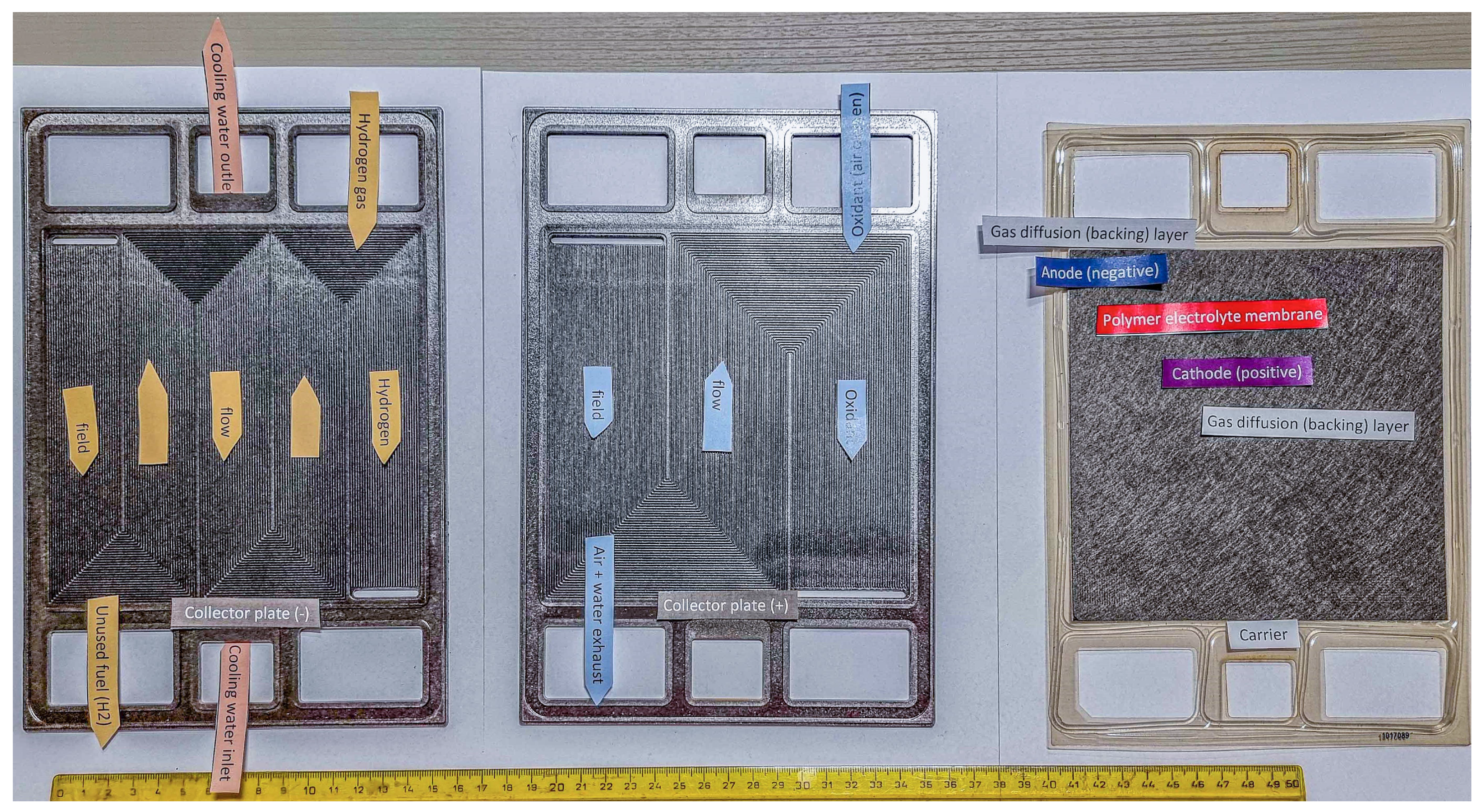
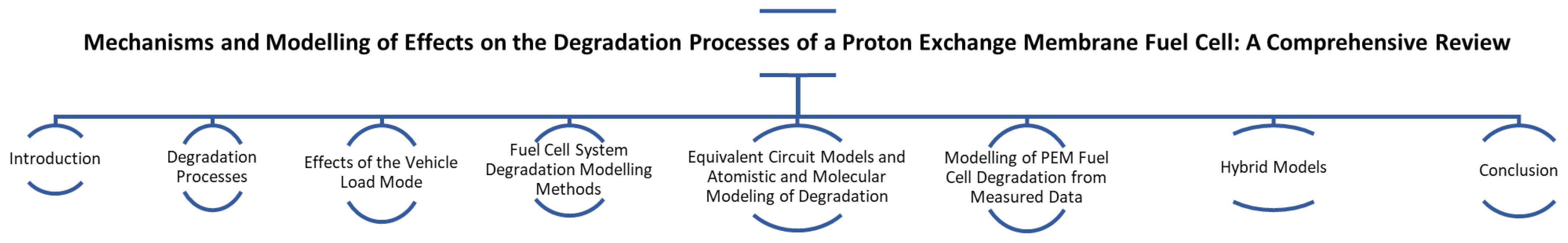
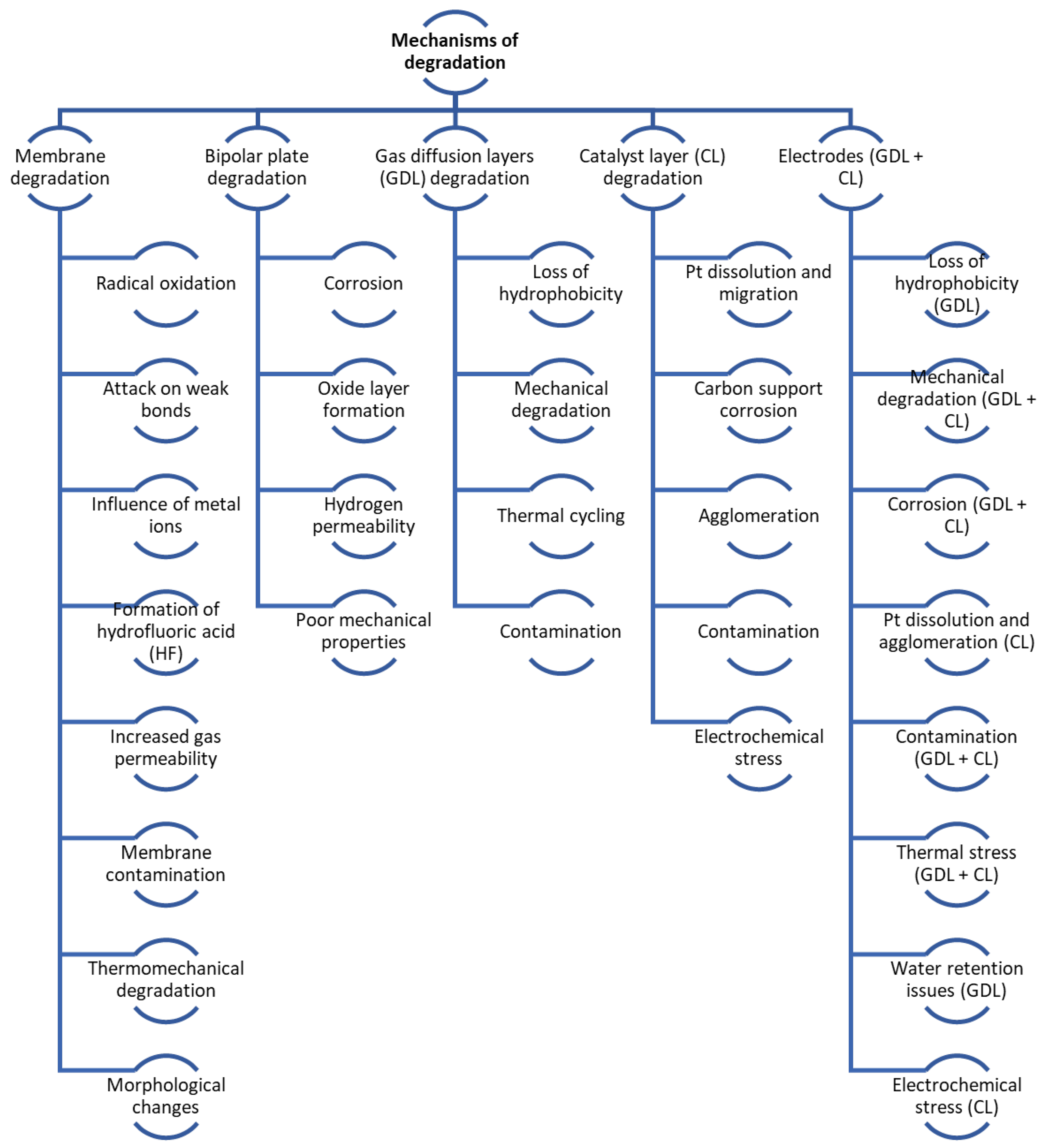
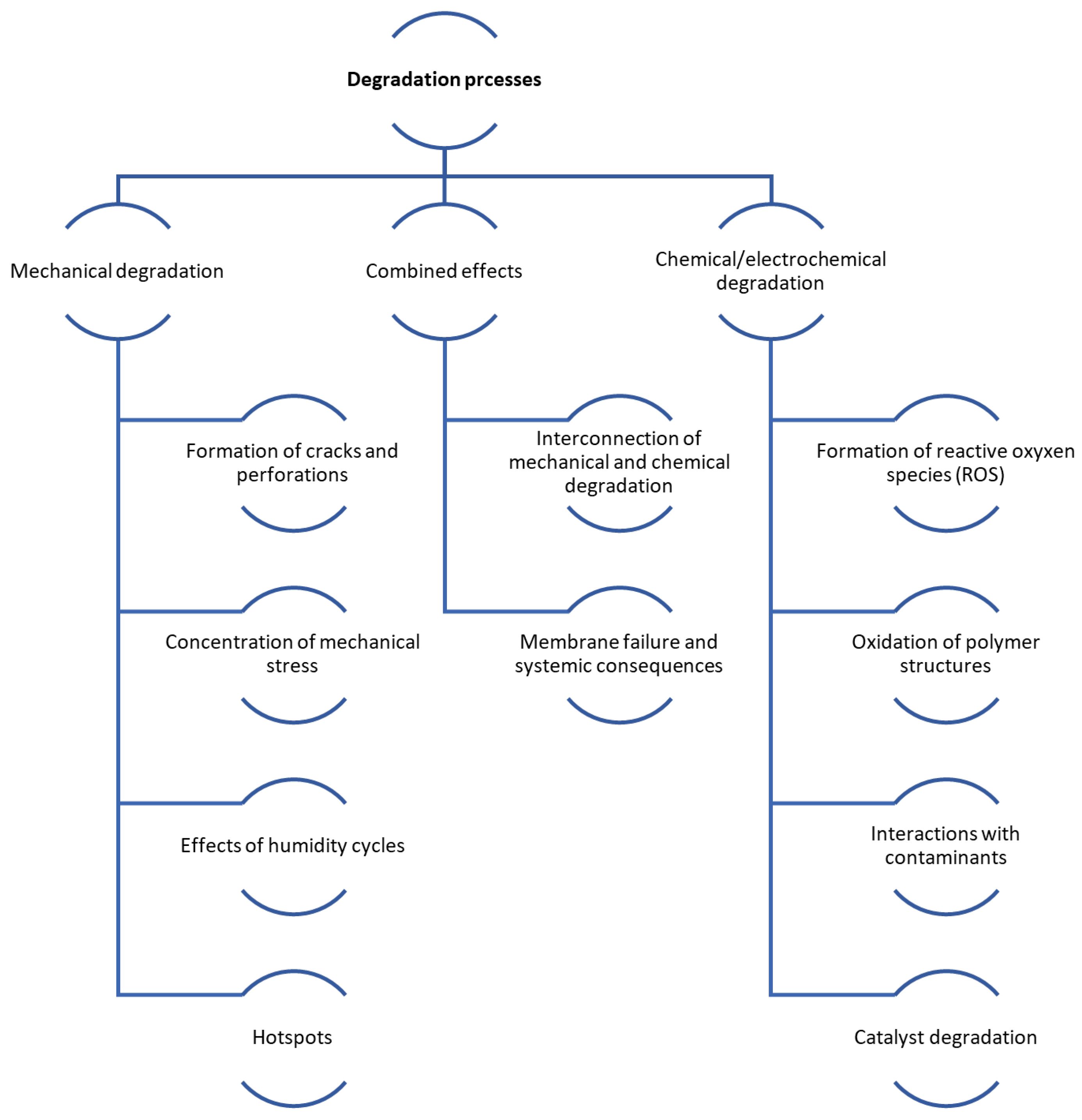
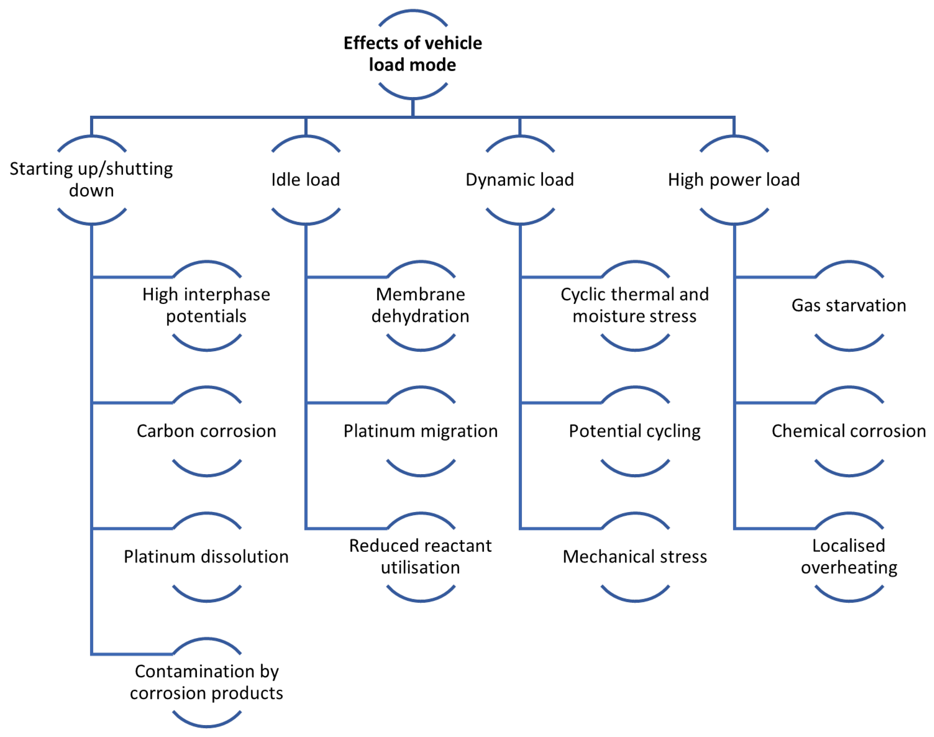
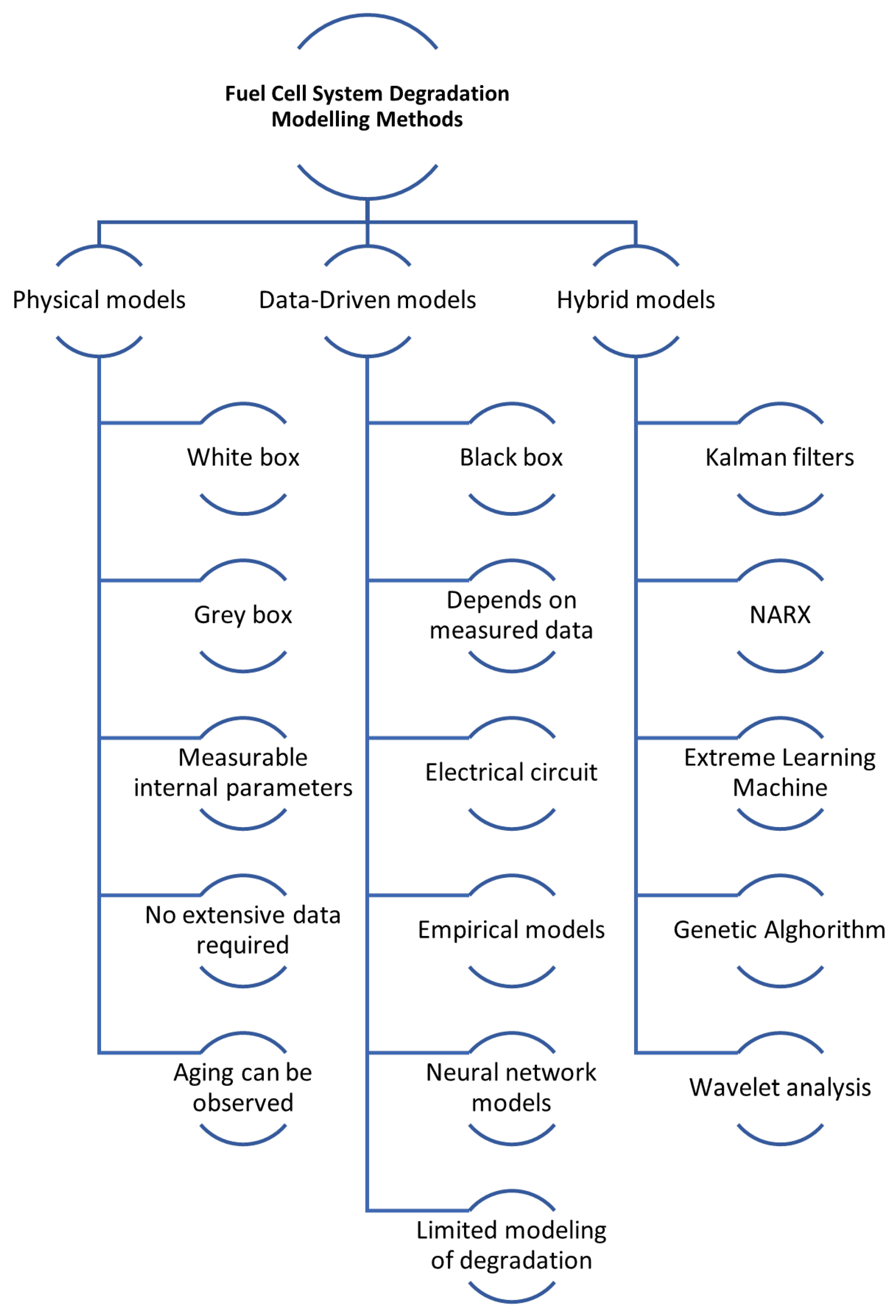
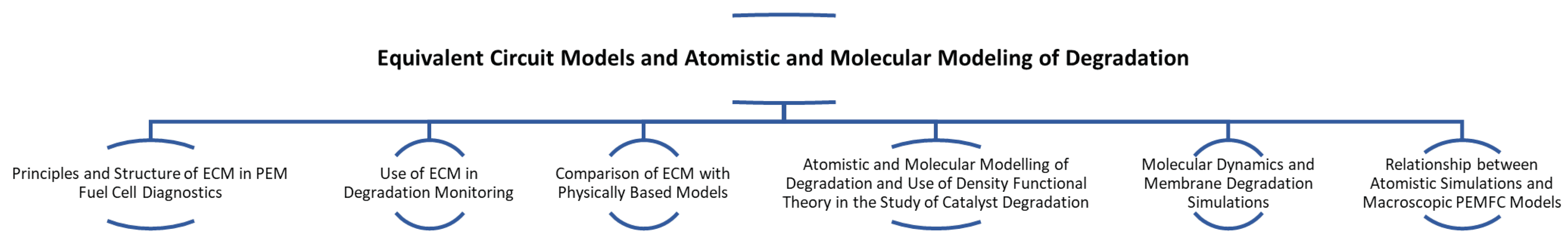
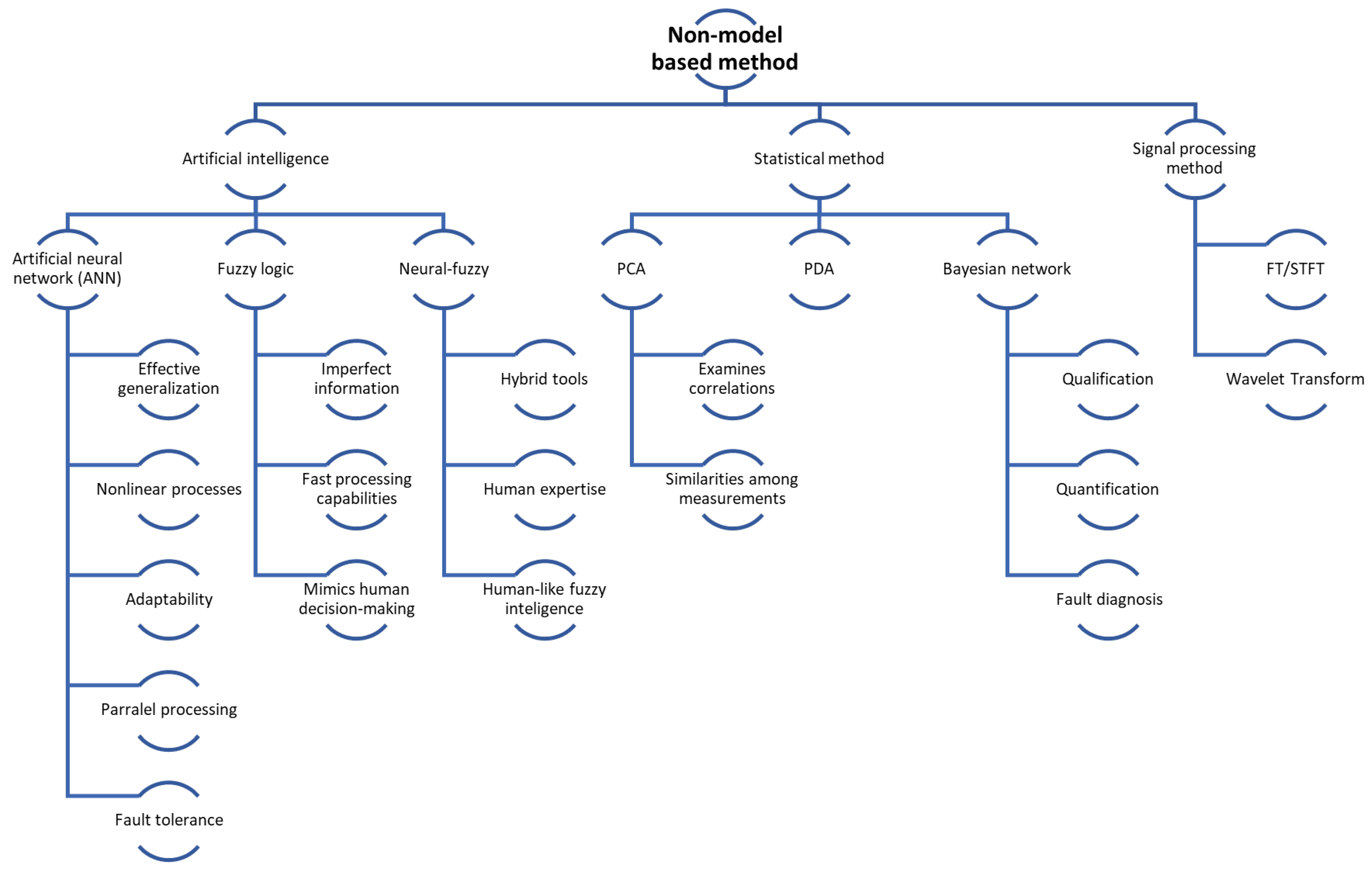
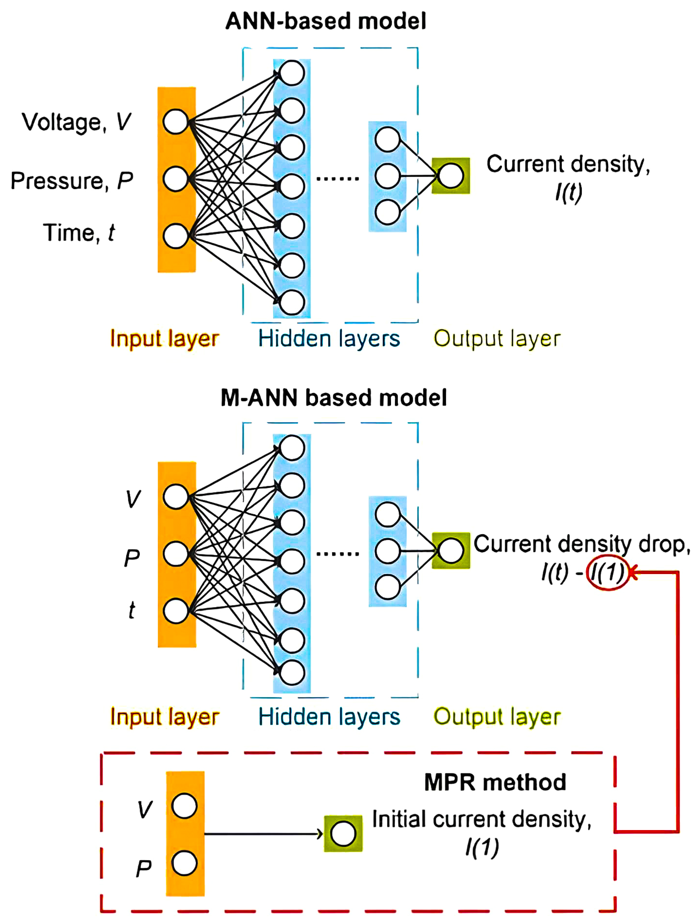
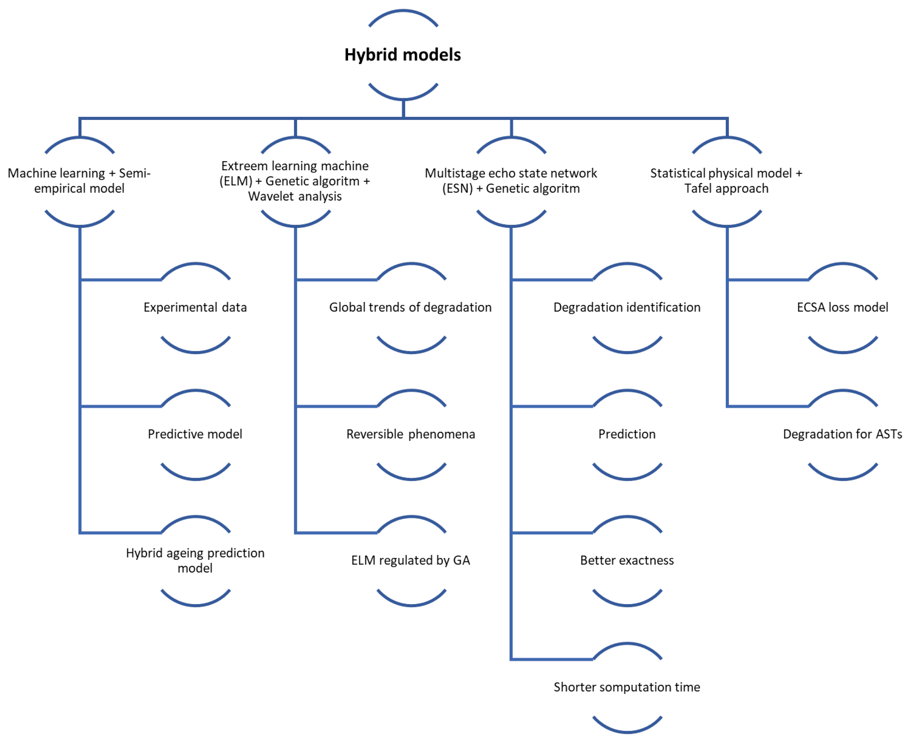
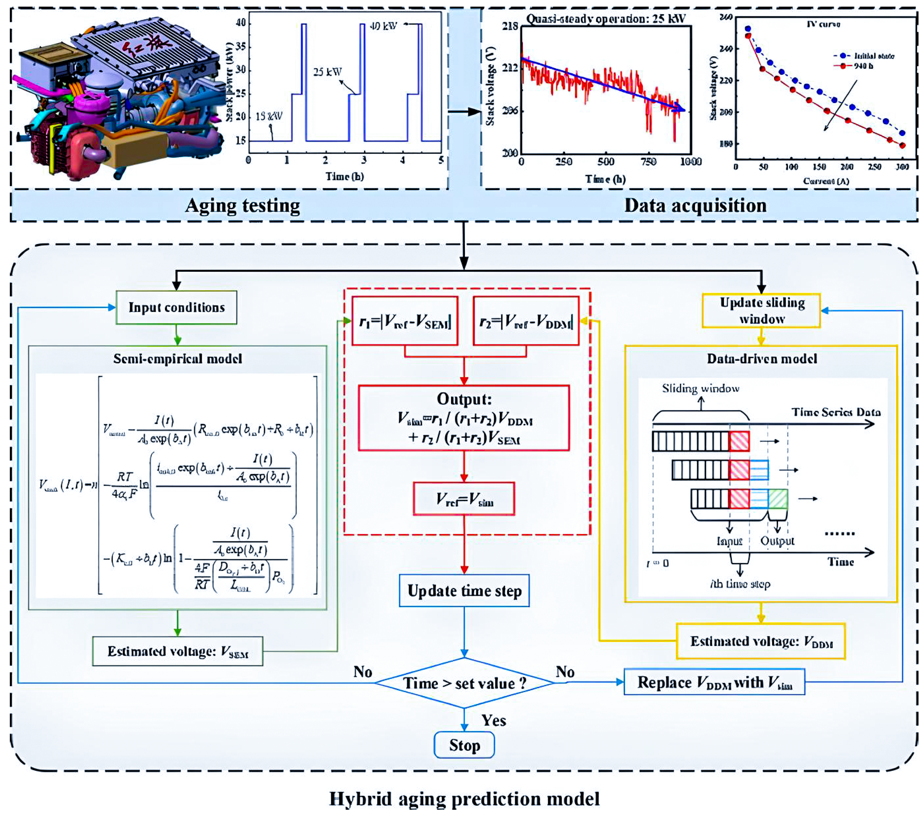
Disclaimer/Publisher’s Note: The statements, opinions and data contained in all publications are solely those of the individual author(s) and contributor(s) and not of MDPI and/or the editor(s). MDPI and/or the editor(s) disclaim responsibility for any injury to people or property resulting from any ideas, methods, instructions or products referred to in the content. |
© 2025 by the authors. Licensee MDPI, Basel, Switzerland. This article is an open access article distributed under the terms and conditions of the Creative Commons Attribution (CC BY) license (https://creativecommons.org/licenses/by/4.0/).