Abstract
The use of conformal cooling channels (CCC) in the injection molding process has revolutionized the polymer industry by enhancing part cooling uniformity and improving cooling efficiency, minimizing undesired defects such as warpage and shrinkage inherent to the process. This review paper provides a detailed investigation of the literature on CCC, with special focus on how computational fluid dynamics (CFD) has been employed to analyze and optimize the thermal performance of the cooling system. Additionally, key aspects of CCC design, including geometry optimization, surface roughness, and flow dynamics, are evaluated to improve cooling efficiency, reduce cycle time, and enhance product quality. Several CFD-based studies are reviewed to highlight commonly used simulation methods and CCC optimization approaches for heat transfer enhancement. Particular attention is given to how simulation tools contribute to design improvement and decision-making, addressing practical constraints related to thermal behavior and manufacturability. Key performance parameters such as pressure drop, temperature uniformity, cooling time, and manufacturing limitations are examined and compared, offering a foundation for future directions to advance CCC design and CFD analysis to optimize injection molding. Aiming at contributing to the academia and the industry, the novelty of this review paper lies in its integrative perspective, providing a comprehensive analysis of coupling designing tasks with CFD simulations. As a result, this paper serves as a valuable resource for researchers and industry professionals aiming to leverage CFD for the development of high-performance, energy-efficient CCC.
1. Introduction
Injection molding is a highly adaptable and indispensable manufacturing technique, capable of producing intricate plastic parts in large volumes with outstanding dimensional precision [1,2]. As a result, it has become one of the most widely employed manufacturing methods, producing plastic parts for all kinds of usage in our daily life and accounting for over one-third of all thermoplastic materials processed in the world [3,4,5]. The rapid growth of industries such as automotive, electronics, medical devices, and packaging, which demand vast quantities of plastic components, has driven significant advancements in injection molding technologies over the past decades [3,6]. This evolution has necessitated continuous optimization to enhance the process’s efficiency and productivity, while the rise of advanced production technology demanding intricate designs, lightweight components, and precision has solidified injection molding as a key area of research, focusing on the production of high-quality products with commercial viability [3,7].
The injection molding process is characterized by a sequence of four different stages, respectively, filling, packing, cooling, and ejection [3,6,8]. This process starts with raw materials being fed into the injection molding machine, where a rotating screw generates frictional heat to melt the material and posteriorly transport the melted material to the screw tip [3]. Once the material is melted at the injection temperature, the filling stage takes place by inserting the melted material into the mold cavity. After filling is completed, the packing stage takes place by forcing additional molten material under elevated pressure to anticipate the expected shrinkage due to material solidification [9]. The subsequent cooling phase aims to reduce the mold’s temperature until the part becomes rigid enough to be removed in the subsequent and final stage, known as the ejection stage, where the mold is opened and the final part is finally released [9].
Among the four stages in injection molding, cooling is both the longest and most critical, representing up to 80% of the total cycle time since the molten plastic (typically heated to 200–300 °C) must cool to below the release temperature (generally 80 °C) before ejection [8,10,11]. Since the polymer melt must be cooled and solidified inside the mold, the mold temperature must remain below the polymer’s phase transition temperature during cooling [12], making this stage particularly complex. The heat from the injected part is dissipated through three different ways: conduction, radiation, and convection, with approximately 90% of the heat being dissipated via forced convection by the coolant flowing within the cooling system [10]. Therefore, improving the cooling rates, and thus reducing the cycle time, has become a central objective in increasing production efficiency [8,9,10]. As a consequence, growing attention has been directed toward the development of innovative solutions to optimize the design and performance of cooling systems, making this an increasingly relevant topic in plastic injection molding research [13]. As their main objective, cooling systems are designed to efficiently remove heat from the mold and the part, so the latter can be ejected without distortion [8,9,14]. To that end, the molten material in the mold cavity should be effectively cooled and properly solidified by dissipating heat through the cooling system [8,9,14].
During the packing and cooling stages of injection molding, the hot molten polymer comes into contact with the cold mold wall, forming a solid layer on this surface almost instantaneously that gradually thickens as the cooling stage progresses until the material is entirely solidified [12,15,16]. However, the rapid formation of this solid layer can negatively impact molding performance, particularly on the filling of parts with a large length-to-thickness (L/T) ratio due to this premature freezing and its consequent weak weld lines resulting from insufficient molecular diffusion between the joining melt fronts [12,17]. Additionally, the resulting differential cooling between the surface and the core of the part often results in undesired structural and morphological heterogeneity, which can be significantly mitigated by reducing cooling and total solidification times [12]. As a consequence of inadequate cooling of the part, two major manufacturing defects may arise, known as shrinkage and warpage, both of which can seriously compromise the final product’s dimensional accuracy and quality [8,18,19].
Shrinkage is an inevitable phenomenon in injection molding, characterized by the reduction in the final part’s size when compared to the mold’s cavity size, which occurs due to the material’s specific volume decrease during the solidification process [18,20]. This phenomenon happens because, in its liquid state, the particles are randomly arranged and their bonding is weak, and when solidification occurs, stronger bonds are formed, leading to a volumetric contraction (shrinkage) [18]. Within this framework, it means that uniform shrinkage does not result in deformations or changes in the part’s shape; instead, it just results in a reduction in the part’s size [20]. On the other hand, warpage results from differential shrinkages on the part, which are mainly motivated by a nonuniform cooling process [18,19,20]. In such cases, uneven heat transfer leads to localized differences in shrinkage, generates internal stresses that distort the part geometry, and causes deviations from the desired final shape [20].
To minimize these defects, cooling systems are integrated into the injection molding process. These systems consist of channels within the mold through which a low-temperature coolant flows, exchanging heat with the mold via forced convection [9,21], while, simultaneously, natural convection occurs between the exterior of the mold and the surrounding air [15,21]. Cooling channels play a vital role in thermal regulation during injection molding, not only reducing cycle times but also significantly improving the final product’s quality [9,22,23]. By shortening the cooling phase—and consequently the overall injection molding cycle—manufacturing times are optimized, leading to increased productivity and reduced costs, energy consumption, and waste [15,24]. Enhancing cooling performance and thus reducing cooling time largely depends on two factors: the mold material and the design of the cooling channels. Since the thermal properties of the mold material remain fixed, refining the design of cooling channels becomes a crucial approach for improving cooling efficiency and shortening cycle time [25].
In addition to optimizing the CCC design, other approaches have been evaluated to enhance heat transfer efficiency during the cooling stage. For instance, using nanofluids as coolants has shown promising results due to their improved thermal conductivity compared to base fluids, achieved by dispersing nanoparticles (e.g., Al2O3 or CuO) in conventional cooling fluids [26,27]. The increased conductivity of nanofluids facilitates faster heat removal and creates a more uniform cooling profile within the mold. Ultrasonic vibration applied to the coolant flow has also been investigated as a means to increase convective heat transfer by disrupting the thermal boundary layer, resulting in a thinner boundary layer that reduces thermal and flow resistance [28]. Although these techniques are not the main focus of this review, their application to enhance cooling efficiency represents a growing area of interest for more efficient and sustainable injection molding processes.
Given the complexity and importance of cooling channel design in injection molding, several studies in the literature have explored alternative solutions to improve cooling efficiency. Among these, integrating CCC design tasks with CFD-based optimization approaches has shown great promise. While various approaches and efforts are evident in the literature, this review aims to provide a structured overview that compares the geometric and thermal performance of different CCC configurations and highlights how computational methods can offer valuable insights to enhance results. The novelty of this work lies in its integrated perspective, connecting CCC design methods with CFD simulations and their capabilities, focusing on delivering valuable contributions to both academic research and industrial applications.
2. Cooling Channels in Injection Molding
Historically, cooling channels in molds have been manufactured using conventional machining methods such as drilling, which enable the creation of straight and relatively simple pathways for coolant flow within the mold structure [24]. While this approach is both easy to implement and cost-effective—factors that contribute to its continued widespread application in the injection molding industry—conventional cooling channels typically offer satisfactory cooling performance and cycle times only for relatively simple molded part geometries [25,29,30]. The limitations of straight pathways become apparent when addressing complex part geometries, as they fail to deliver uniform and efficient cooling across the mold cavity. Moreover, the design and fabrication of these channels have traditionally been constrained by the capabilities of conventional manufacturing methods and the absence of advanced design methodologies, further limiting the ability to achieve optimized cooling configurations [31].
The inability to manufacture complex three-dimensional contour-like cooling channels using conventional methods often results in inefficient cooling due to uneven heat transfer between the mold and the molded part [24]. For instance, in the case of a straight drilled cooling channel intended to cool a curved cavity (as illustrated in Figure 1), distance variations between the cooling channel and the curved cavity along the mold geometry lead to uneven cooling rates across the cavity surface. This nonuniform cooling induces differential shrinkage and warpage in the molded part [29]. Additionally, since the molded part might be ejected only once the cavity temperature has fully dropped below the ejection threshold, the overall cooling time is dictated by the slowest cooling regions. Specifically, these regions correspond to areas where the greatest distance between the cavity surface and the cooling channel is observed (at the far ends of the cavity) rather than where the distance is shortest (near the middle of the cavity). Consequently, the cooling process takes longer, as the part requires additional time to solidify in these less efficient regions [29].

Figure 1.
Schematic of a straight-drilled cooling channel. Obtained from [29].
For those reasons, the cooling system must be designed in an efficient manner to ensure even temperature distribution throughout the molded part during the cooling process. This approach is critical for maintaining product quality by minimizing issues such as differential shrinkage, internal stresses, and ejection problems [15]. It means that, during the cooling stage, since the areas of the part closer to the cooling channels cool more rapidly than areas farther away, these temperature differences lead to differential shrinkage on the part, which can induce thermal stresses. If these stresses become significant, they may result in warpage, compromising the final quality of the manufactured part [32]. Thus, cooling channels must be specifically tailored and optimized for the geometry of each part to achieve effective heat transfer between the mold and the part. Key parameters such as the location, size, and shape of the cooling channels must be carefully determined to enhance the cooling stage and subsequently reduce cooling time [15,25]. Optimized cooling channel designs can lead to significant improvements in manufacturing efficiency and, in some cases, for instance, a properly designed cooling system has the potential to reduce cooling times by up to 80% and overall cycle times by 60–70% [29].
Due to these constraints on reducing cooling time and obtaining uniform cooling to improve the final product quality, the industry started to focus its attention and research on developing and studying alternative methods to manufacture conformal cooling channels (CCC), which consist of a network of cooling channels that remain equidistant from the mold cavity along its pathway [29,33]. The design of conformal cooling channels is characterized by channels that conforms to the contours of the part’s geometry within the mold, and it has proven to be a highly promising in substituting conventional straight-drilled cooling systems because it provides a more uniform and efficient temperature distribution, which can significantly reduce part imperfections and cooling time [25,29,33]. For instance, consider a curved cooling channel for the same curved cavity shown in Figure 1, as illustrated in Figure 2, where the distance between the channel and the cavity surface is always constant. This approach ensures a uniform cooling rate at the cavity surface, which provides a more efficient cooling performance, avoiding shrinkage differentials and decreasing cooling time [29].
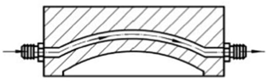
Figure 2.
Schematic of a conformal cooling channel. Obtained from [29].
By that, it is clear that an optimal design of the cooling channel network is crucial to manufacture parts efficiently, reliably, and with reduced cycle times [29]. Besides the cycle time reduction, enhanced part quality is one of the most notable advantages of implementing conformal cooling channels in injection molds since it improves dimensional accuracy by avoiding warpage and potential defects, allowing tighter tolerances and overall better part consistency. However, achieving the desired cooling performance through CCC designs must be balanced with the challenging task of manufacturability [29].
2.1. Conformal Cooling Channels Through Additive Manufacturing
The impossibility of developing molds with conformal cooling channels by conventional subtractive manufacturing methods led the industry to resort to additive manufacturing (AM), which is an approach that provides significant design flexibility and enables the production of components with intricate internal structures due to its layer-by-layer material deposition approach [10,23]. This manufacturing technology is considered a disruptive method to develop complex molds with geometric constraints, which can bring several advantages for the industry when compared to conventional methods, this being one of the fastest-growing industrial sectors in the USA [10,34]. Additive manufacturing (AM) refers to the process in which material is deposited layer-by-layer to produce a solid part, while traditional (subtractive) methods, like drilling, refer to the process of removing material from a solid block to create the desired part [34]. The AM approach brings several advantages to the industry, such as the flexibility of designing models, consolidation of complexity, and reduction in tooling costs and material and financial wastes inherent to conventional manufacturing processes [34].
Additive manufacturing encompasses a variety of techniques that build objects by layered material deposition. Among these, powder-based additive manufacturing refers to a group of methods where metal powder is deposited and fused layer by layer to produce three-dimensional parts [29]. The manufacturing process starts with a 3D model of the part created in a computer-aided design (CAD) environment, which is posteriorly exported to a specialized software that slices this model into layers of a specified thickness, forming the final geometry to be built [35]. This technique is well-suited for manufacturing parts with intricate 3D geometries, such as conformal cooling molds, where laser powder bed fusion (LPBF) has emerged as the most commercially viable AM technology to manufacture high-quality tools and conformal cooling molds made of metal [29,36]. The laser powder bed fusion (LPBF) is an advanced additive manufacturing method for metals capable of producing 3D objects by employing a laser beam to fuse and bind metal particles on a powder bed in a layer-by-layer process, guided by the 3D sliced model generated from the specialized software [10,29]. The distinctive fabrication process of LPBF overcomes many of the limitations of traditional manufacturing techniques, such as challenges associated with complex shapes, materials, and functionalities, providing versatility that turns this method an ideal solution to manufacture conformal cooling channels with different cross-sectional shapes and architectures in an easy manner [10,29]. As a consequence, the geometric freedom enabled by LPBF facilitates the effort of design and manufacture of mold geometries with conformal cooling channels precisely distributed to match the shape of the mold cavity, also enhancing the desired cooling uniformity and improving the quality of the injected molded parts [10].
Although printed molds with conformal cooling channels using LPBF technology demonstrate significant advantages in reducing cycle time and enhancing part quality, the quality of the surface and the dimensional precision of cooling channels printed by LPBF are still limited when compared to those produced with straight-drilled methods [29]. This limitation arises, among other factors, from residual unmelted powder particles from the previous layer that undesirably remain on the subsequent layer, resulting in surface imperfections [29]. For this reason, hybrid alternatives (additive + subtractive manufacturing) to fabricate molds have been investigated to avoid these imperfections. Additive manufacturing and subtractive manufacturing have complementary characteristics, with AM offering the ability to manufacture intricate structures in a flexible and efficient manner, while subtractive manufacturing (such as machining) offers the ability to manufacture parts with high dimensional accuracy [29].
These surface imperfections in conformal cooling channels caused by unmelted powder particles also result in an undesired degree of surface roughness, which can eventually affect the quality of the mold and the heat transfer coefficient [29]. To mitigate these issues, a promising approach involves mechanically finishing the inner walls of the printed layer prior to printing the subsequent layer [29]. A schematic description of the abovementioned approach is shown in Figure 3, where the AM stage occurs by using a laser beam to melt the metal powders presented on a powder bed; subsequently, once an additive layer is completed, the milling cutter machines the part being built to enhance surface finishing. Once these steps are completed, the powder bed is prepared to receive another layer of powder by lowering it to one layer high, and this process is sequentially repeated until the part is finished [37].

Figure 3.
Schematic of a hybrid process. Obtained from [37].
This hybrid approach requires the integration of two independent manufacturing systems operating within the same workspace and sharing a common coordinate origin while it also should ensure that the additive system and cutting tool do not interfere with each other, requiring the use of specialized machining tools [29]. However, the high cost of this specialized machine tool is considered a huge constraint for the industry, which has made the industry adopt a more feasible and economical alternative by using two separate machining tools for additive and subtractive manufacturing stages, respectively. To this end, two purposes are targeted at using a hybrid approach: (1) fabricating hybrid molds and (2) postprocessing the as-printed surfaces [29].
When fabricating hybrid molds, the process typically involves creating the straight-drilled channels insert of a mold through the subtractive manufacturing method (referred to here as Part (1)) and conformal cooling channels insert through additive manufacturing methods (referred to here as Part (2)). To bond these two parts, two approaches can be employed: either by additively manufacturing the Part 2 directly on Part 1, using Part 1 as a baseplate for Part 2; or separately manufacturing both parts and posteriorly bolting these two parts together, which requires screws to secure the assembly [29]. This hybrid manufacturing approach introduces a critical concern regarding the bond strength between the additively and subtractively manufactured regions, particularly when different materials are used for each part [29]. A schematic representation of a hybrid additively/subtractively manufactured conformal cooling channel is shown in Figure 4, where the blue zone represents the mold manufactured through the subtractive method (Part 1) and the green zone represents that manufactured through the additive method (Part 2).
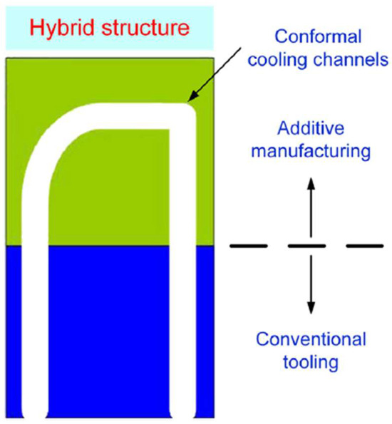
Figure 4.
Schematic of hybrid subtractively (blue) and additively (green) manufactured CC mold. Obtained from [29].
As previously mentioned, the mold insert sometimes can be divided into two parts, where the more intricate portion, containing conformal cooling channels, is additively manufactured on simple machined baseplates, as exampled in Figure 5, from the work carried out by Andreas Kirchheim [36]. The complex tool, illustrated in Figure 5a, consists of an injector side (depicted in blue) and an ejector side (depicted in orange). The injector side was fabricated entirely through additive manufacturing, while the ejector side was designed as a hybrid tool where the segment containing the cooling channels (orange) was produced using the LPBF method on the top of a conventionally manufactured baseplate [36].
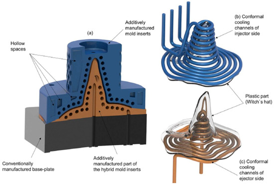
Figure 5.
(a) A sectional view of the mold insert on the ejector side (orange) and injector side (blue), featuring conformal cooling channels near the cavity; (b) conformal cooling channels presented on the injector side; (c) conformal cooling channels presented on the ejector side. Obtained from [36].
The other purpose of jointly using additive and subtractive manufacturing methods is to postprocess the printed surface, which means that the subtractive stage will occur after the additive one, working as a surface finishing process. In general, mold surfaces quality obtained from additive manufacturing methods are not as good as when obtained with mechanically machined methods. Depending on the mold surface quality required, the resulting mold obtained through AM can be insufficient, which can lead to the necessity of mechanically machining the mold after the AM process to appropriately improve its dimensional accuracy [29]. Keeping this in mind, as the mechanical machining stage occurs after the additive manufacturing process (and material will be removed), it means that the printed part must be larger than the desired designed final part to ensure the proper dimensions at the end of the process. Regarding the internal surface of conformal cooling channels, CCC must initially be designed with a smaller diameter since subtractive manufacturing will remove material and increase its diameter. Due to the geometric complexity of the channels, this subtractive process on CCC surfaces can be achieved through polishing with abrasive flow machining, leveraging the flexibility offered by the abrasive flow technique [29,38].
2.2. Flow Type Importance
Besides the fact that conformal cooling channels lead to uniform cooling and an optimized cooling rate, another great benefit of implementing conformal cooling channels by additive manufacturing methods is that it allows the type of the coolant’s flow obtained throughout the channel to be considered: laminar or turbulent. Both laminar and turbulent flows take the heat away from the mold, but it is imperative to note that the type of flow is a very important factor in convective heat transfer because it dictates the way that the molecules of the coolant interact with each other [39]. For this reason, the heat transfer between the mold and the coolant is significantly affected depending on the type of flow of the coolant, which makes the approach of changing the flow pattern from laminar to turbulent flow one of the traditional methods to improve the convective heat transfer coefficient [10]. In a laminar flow, the fluid flows in layers parallel to the wall surface, with no large-scale movement along the direction of heat flow. This results in a significant temperature gradient, which increases the thermal resistance and thus reduces the efficiency of convective heat transfer [10,39]. On the other hand, in a turbulent flow, the chaotic movement of the fluid mixes its molecules significantly, which consequently decreases the temperature gradient (more uniform temperature on the coolant), enhancing the convective heat transfer [10,39]. In doing so, it is observed that the Reynolds number in the flow represents a very important role in the cooling systems by being inversely related to the cooling time since an increase in turbulence (represented by a higher Reynolds number) enhances heat transfer between the coolant within the cooling channel and the mold. This improved heat transfer, driven by greater mixing of the coolant flow at higher degrees of turbulence, results in a lower average mold temperature, consequently reducing the overall cooling time [29]. With this in mind, additive manufacturing is able to optimize the cooling process by increasing heat transfer using a method known as the passive technique, which means that no additional power source is required to increase the heat transfer; instead, it relies on optimizing or modifying the geometry and surfaces, such as including treated surface, rough surfaces, extended surfaces, and vortex generator devices [40,41].
2.3. Roughness Effect
Many studies have been performed and found in the literature to further understand the effect of roughness surfaces for laminar and turbulent flows. As discussed in the work carried out by Kadivar et al. [42], the surface roughness of the cooling channel has the ability to impact the fluid flow and heat transfer by increasing the pressure drop, affecting the transition between laminar and flow regimes and stimulating secondary flow motions (which directly improves flow mixing and enhances heat transfer) [42]. This influence from the surface roughness is motivated by the disturbance of the laminar sublayers close to the channel surface, which is a fluid layer adjacent to a solid surface that experiences altered velocity due to the frictional forces between the fluid and the surface. This disturbance increases the mixing and energy dissipation in the fluid, which results in an increased heat transfer rate and reduces the temperature gradient across the fluid. In contrast to the laminar flow regime, surface roughness has a strong influence on friction factors and heat transfer coefficients in the transitional and turbulent flow regimes, since in these regimes the viscous boundary layers are thin and near the wall, where most temperature and velocity gradients occur and their disturbance significantly affects both pressure drop and heat transfer characteristics [43].
While surface roughness negatively impacts pressure drop—requiring increased pumping power for the cooling system—it also positively contributes to an enhanced heat transfer rate on the system [41,43]. Therefore, designing cooling channels with a specific level of surface roughness requires balancing these competing objectives (pressure drop and heat transfer). In complex cooling channel systems, substantial local pressure drops may disturb the uniform distribution of the flow in different branches or even avoid coolant flow in certain branches; as a result, the overall pressure drop between inlet and outlet of the channel increases, requiring greater pumping power to uniformly circulate the coolant throughout the channels and resulting in elevated energy consumption and thereby financial costs [44]. This framework enables additive manufacturing to offer an optimum approach: altering surface roughness amplitudes in different locations of the channel based on geometry constraints, improving heat transfer while minimizing unnecessary pressure drop [41].
3. Heat Transfer Analysis of Cooling Systems in Injection Molding Through Computational Modeling
To obtain deeper insights into the heat transfer efficiency using conformal cooling channels in the injection molding process, numerical modeling has become an important role. The adoption of computer-aided engineering (CAE) in this field has enabled engineers and researchers to analyze and optimize various aspects of cooling channel design, fluid flow, and heat transfer, contributing to an enhanced overall process efficiency by improved part quality while reducing cycles times. The main stages of computer-aided engineering (CAE) studies concerning conformal cooling channels are commonly accomplished from a three-dimensional model of the geometry designed on CAD software, which are then exported to a CAE software to perform the computational modelling analysis [25]. With the generated geometry design, several studies can be performed on a CAE environment to predict and comprehend the flow behavior through the CCC while also helping in the identification of critical zones and potential opportunities for geometry improvements. Additionally, the thermal performance of the cooling channels under different conditions can be assessed to evaluate heat exchange efficiency with the mold. These numerical modelling simulations offer significant benefits to the industry by eliminating the costly trial-and-error procedure inherent when designing injection molds, thereby significantly reducing both development time and costs [25,45]. Because of the growing demand and benefits of numerical modelling, several software have been developed and used to analyze the coolant flow and heat transfer in cooling channel systems, enabling further optimization of the injection molding process. Among some of the most widely employed software in this field, ANSYS-Fluent and Autodesk Moldflow Insight have played an important role in many studies found in the literature.
Additionally, the extensive utilization of plastics in a wide range of applications also served as a strong motivation for designers to engage in research efforts aimed at optimizing mold designs, enhancing productivity, and improving the quality of the manufactured components [45]. It led to a series of research work carried out by the academy and industry where the majority of proposed design and optimization algorithms, as well as manufacturing methods, were accomplished by case studies to simulate and compare results under different conditions. For instance, Mohamed et al. [46] employed Autodesk Moldflow Insight to introduce and simulate various cooling channel configurations for an injection molded plastic part, as shown in Figure 6, where they analyzed and compared the performance of these configurations based on factors such as time to reach ejection temperature, volume shrinkage, temperature profile, and part warpage. In all the simulations performed, each cooling channel configuration was designed with the same diameter of 10 mm and under the same conditions (such as coolant temperature, melt temperature, and turbulent flow); thus, the only variable parameter was the distribution of cooling channels in the mold. The comparison between the results aimed at identifying which configuration was more appropriate to provide uniform cooling of the part while reducing cycle time, and their investigation led to the conclusion that, among various cooling channel configurations, fully conformal cooling channels proved to be the most suitable cooling systems for the manufactured plastic part. This configuration provided the lowest time for the part to reach ejection temperature (lowest cooling time) while exhibiting lower volumetric shrinkage and reducing warpage of the part due to cooling uniformity.

Figure 6.
Cooling channel configuration (a) normal, (b) conformal combined with baffle, (c) conventional combined with conformal, and (d) fully conformal. Obtained from [46].
In a similar research work carried out by Advait C. Purav et al. [47], an examination of three different cooling system configurations, namely traditional, conventional, and conformal cooling channels, was conducted via simulations for the performance of an injected molded kidney tray of 3 mm thickness. All channel configurations were designed with the same diameter of 15 mm and employing the same simulation conditions; thus, the only variable parameter was the distribution of cooling channels in the mold, as shown in Figure 7. The performed study revealed that, compared to conventional configuration, conformal cooling channels were able to reduce part cooling time by approximately 18.7%, reduce mold temperature after cooling by 7.8%, reduce freezing time by 16.6%, reduce the volume shrinkage by 52.6% and reduce the total warpage by 16.5%. From these results, a new study was performed by using the same conformal cooling channel configuration under the same simulation conditions, but for a kidney tray with a 2 mm thickness. The comparative results are shown in Figure 8.

Figure 7.
Cooling channel configuration (a) traditional, (b) conventional, and (c) conformal. Adapted from [47].
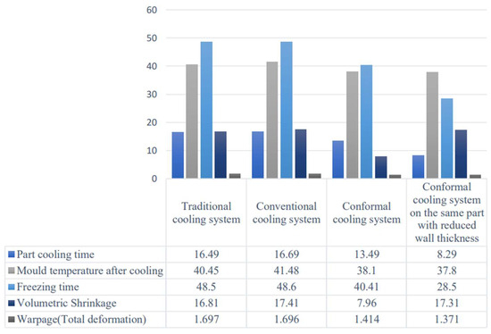
Figure 8.
Comparative results of performed simulations. Obtained from [47].
In the work carried out by Hanniffy et al. [48], finite element analysis (FEA) was employed to analyze and compare thermal aspects when employing traditional and conformal cooling channels in the production of a computer mouse through injection molding. As shown in Figure 9, the traditional cooling system (a) was designed to be drilled straight in the mold, while the conformal system (b) was designed to follow the part geometry. The results showed the temperature of the mold to be, on average, 16% lower when using conformal cooling channels compared to traditional channels, leading to a shorter cycle time that would significantly increase the productivity of the product.
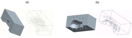
Figure 9.
Cooling channel configuration (a) traditional and (b) conformal. Adapted from [48].
In terms of optimizing cooling channels, the increasing need for conformal cooling channels for optimal performance has marked the significance of defining ideal parameters. For instance, Kanbur et al. [49] investigated CCC metal additive manufacturing with multiple design parameters and a multiobjective function consisting of cooling time, temperature nonuniformity, and pressure drop. To determine the best CCC system, the authors developed three configurations (circular, serpentine, and tapered patterns) and used a multiobjective optimization algorithm with the MATLAB Optimization Toolbox to identify the optimal configuration and design parameter combinations, leveraging CFD simulations validated by experiments. Compared to conventional cooling channels, the developed CCC achieved a 62.9% improvement in cooling performance, and the quality of the printed CCC was inspected, revealing errors between the CCC design and the printed parameters to be less than 5%. In another work, Kitayama et al. [50] undertook a numerical and experimental (3D printed CCC molds) exploration of CCC cooling performance in plastic injection molding (PIM), determining cycle time and warpage as key indicators of cooling effectiveness. In general, a short cycle time can lead to large deformation (warpage) of the part in PIM due to the nonuniform cooling of the plastic product, whereas a small warpage results from a long cycle time. Keeping this in mind, the main goal of this work was to observe the trade-off (Pareto frontier) between cycle time and warpage (these two aspects being the objective functions) in order to improve them simultaneously. To achieve this, a multiobjective design optimization was formulated, where the authors identified melt temperature, injection time, packing pressure, packing time, cooling time, and cooling temperature as the design variables for the cooling channels. The CCC was designed based on the designer’s experience, while PIM process parameters were optimized through sequential approximate optimization (SAO) by identifying the Pareto frontier using a radial basis function network. In their numerical results on a conventional cooling channel, it was observed that elevated packing pressure, long packing time, low melt temperature, high cooling temperature, and long cooling time contributed to reducing warpage. Nevertheless, the extended cycle time needed to achieve this warpage reduction was an obstacle, since cycle time minimization was also an objective, which led the authors to redesign the cooling channel in a conformal manner to ensure not only warpage reduction but also cycle time reduction. From that, a conformal cooling channel was designed and its numerical results allowed us to observe that warpage reduction with elevated packing pressure, short packing time, low cooling temperature, and short cooling time was achievable with conformal cooling channels. It led them to conclude that the Pareto frontier of the conformal cooling channel was significantly better than the Pareto frontier of the conventional cooling channel, showing a 53% improvement in cycle time and 46% in warpage. The comparison of the results between numerical simulations and the experiment is shown in Figure 10.
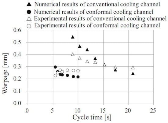
Figure 10.
Comparison of Pareto frontier between numerical simulation and experiment. Obtained from [50].
Wu Tong et al. [51] worked on a framework for dies designs with optimized CCC in the context of additive manufacturing, whose framework encompassed multiple modules: (1) process and material modeling; (2) multiscale topology optimization; and (3) experimental testing, calibration, and validation. Their objective was to enhance the die thermal performance while minimizing its weight. To this end, a multiscale topology optimization model was developed and employed, while numerical simulations were conducted to assess part quality and estimate the cycle time and tooling longevity. In another approach, Wu and Tovar [52] proposed the integration of thermal–fluid topology optimization for CCC design within injection moldings, introducing a coupled algorithm that combines thermal and fluid topology optimization aiming at designing and improving CCC performance. In topology optimization, a multiobjective function is formulated by combining two objectives related to thermal and fluid performance using weighting coefficients. This method replaces the channel positioning to a distribution problem, which makes it directly dependent on the effects of heat conduction, flow resistance, and both natural and forced convection [52]. This problem was framed based on a coupling of the convection–diffusion equation and Navier–Stokes equations, which uses analytical sensitivity derived from the adjoint method to solve the problem by a gradient-based optimization algorithm called the method of moving asymptotes (MMA). This algorithm produces a 2D conceptual design that achieves optimal heat transfer and a balanced flow, which is subsequently transferred to a CAD software (Rhinoceros) where it is converted into 3D channels and mapped to a morphological surface that conforms to the shape of the injected part, as illustrated in Figure 11 [52]. The proposed method in this work was applied to design an optimal CCC of a core insert, where the morphological surface was determined as the cylinder near the injected part, as shown on the left side of Figure 11. Figure 11a shows that the initial parameters for the study were defined, leading to the results of the thermal–fluid topology optimization shown in Figure 11b. To ensure flow balance, identical velocities were set along the central line of the different branches, and the formulation of a fluid topology optimization problem was performed for the domain shown in Figure 11b, resulting in the outcomes shown in Figure 11c. Finally, the conceptual design was turned into a 3D CAD model and mapped to the morphological surface, as illustrated in Figure 11d,e. After that, the design was remeshed using Mimics 3-Matic software, and the simulations were performed in COMSOL Multiphysics. The results demonstrated sufficient flow rates throughout all channels and uniform fluid temperature under worst case, as shown in Figure 12a,b, respectively.
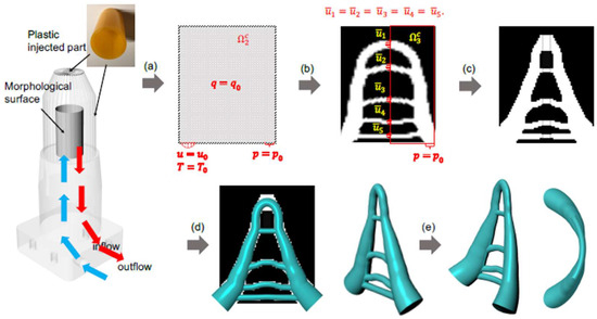
Figure 11.
Design procedure of the conformal cooling system, with (a) defined initial parameters, (b) same velocities set along the branches central line, (c) resulting outcomes of the optimization, (d) and (e) the 3D CAD model. Obtained from [52].
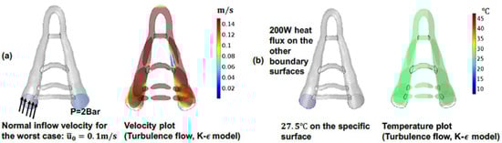
Figure 12.
Thermal–fluid coupled simulation for cooling system, demonstrating (a) sufficient flow rate throughout all channels and (b) uniform fluid temperature. Obtained from [52].
Wang et al. [53] introduced a novel method for thermal-load-based topology optimization to increase heat transfer and reduce pressure drop within the conformal cooling channels. The goal was to achieve an optimal channel configuration that provides a low pressure drop while ensuring a high heat transfer rate. For that, a series of optimized 2D results were converted into 3D channels that conform to the geometry of a given injection casting and posteriorly exported to COMSOL Multiphysics software in order to perform injection molding simulations. In this study, as shown in Figure 13, the authors executed a thermal fluid topology optimization process within a specified two-dimensional domain, in which the thermal load distribution was determined according to the cooled casting geometry. From that, a three-dimensional conformal cooling network was generated using the optimized channel configuration.

Figure 13.
Schematic of conformal cooling process performance improvement by performing thermal-load-based topology optimization. Obtained from [53].
Keeping that in mind, a multiobjective function was considered in the topology optimization algorithm to balance the maximization of thermal dissipation and minimization of pressure drop, with weighting factors (f1 and f2) that could control whether the results would prioritize either maximizing the heat transfer rate or minimizing the pressure drop, as shown in Figure 14.
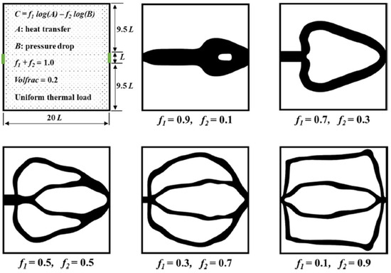
Figure 14.
Topology-optimized results based on multiobjective function control with different weighting factors. Obtained from [53].
The topology optimization process, as illustrated in Figure 15, begins with the initialization of pseudo densities Xi (where 0 < Xi < 1) within the region of interest in the design: Xi = 1 specifies that the region contains a fluid; thus, thermofluidic dynamics equations are followed; Xi = 0 specifies that the region contains a solid material; thus, solid heat-transfer equation is used; and 0 < Xi < 1 specifies that the present material is somewhere between a solid and a fluid material. For that, the total region was initially discretized into several elements (N) using the finite element method (FEM) and the pseudo densities were iteratively updated according to the defined objective functions and limitations until a well-defined material distribution was acquired. Subsequently, a finite element solver is executed using present pseudo densities as inputs, establishing boundary conditions and thermal load distribution by specifying nodal values of interest. Initially, it computes pressure and velocity fields based on the fluid dynamic equations, where the velocity field is subsequently integrated into the energy conservation equation to determine the temperature field. Subsequent steps involve the calculation of the objective function and volume limitation, along with the acquisition of sensitivity information. To ensure mesh independence and control the overall channel length, a density filtering process is carried out, taking into account sensitivities. The filtered sensitivity data are subsequently fed into the MMA algorithm (working as input data), which generates updated pseudo densities aligned with a reduced objective function value. Then, the convergence is evaluated through a comparison of the maximum alteration of the pseudo densities prior to and post optimization with tolerance thresholds. If convergence is achieved, pseudo density distribution that was obtained through optimization is then generated and presented. In the opposite case, the process repeats by reintroducing these updated pseudo densities acquired from the optimization step into the finite element solver. In summary, the objective of the whole process was to determine the pseudo density distribution that minimizes the objective function within the prescribed volume limitations. From that study, Wang et al. [53] concluded that this approach led to optimal channel layouts that effectively combined an elevated heat transfer rate and low pressure drop.

Figure 15.
Flowchart of thermal-load-based topology optimization. Obtained from [53].
In the work carried out by Martowibowo et al. [54], CCC systems were studied and applied in the production of a bowl-shaped product, with the optimization focused on determining the machine setup parameters such as injection pressure, melting temperature, packing pressure, and packing time. The aim of this work was to optimize the injection molding process by reducing cycle time, applying Moldflow and genetic algorithm (GA) methodologies to optimize the design and setup parameters [54]. A genetic algorithm is an approach inspired by Charles Darwin’s theory of evolution, where the algorithm keeps evolving until it finds the optimum value and solution to a given problem (such as reducing cycle time), which, in this work, was executed in the Matlab software. It starts with the generation of multiple random solutions (which may be initially impractical) to the problem, and through continuous evolution, the algorithm gradually refines these solutions until it reaches the optimum and desired solution [54].
In their work, the relationship between the parameters was determined by using the design of experiment (DOE) approach, followed by Moldflow simulations to assess the potential for volume shrinkage and wall shear stress to surpass maximum thresholds at the minimum cycle time obtained. The process began by designing and making injection molds with conformal cooling channels and then performing simulations in Moldflow to collect the cycle time with the parameter combinations determined by DOE. The simulation results from Moldflow were used to establish a relation between the independent variables (melting temperature, injection pressure, packing pressure, packing time) and response variable (process cycle time), which were then employed by GA in Matlab for optimizing process parameters, where the primary goal of the work was to minimize the cycle time while ensuring volumetric shrinkage and wall shear stress within established limits. Finally, the optimized parameters obtained through GA were used in Moldflow to perform new simulations to verify the optimization results, which were posteriorly validated by experiments. With that work, the authors have concluded that the combination of Moldflow and GA successfully provided optimum injection molding parameters for a given CCC, with the simulation results closely matching experimental data, showing less than a 1% difference in the cycle time.
Kanbur et al. [55] proposed a neural network-integrated multiobjective optimization of 3D-printed conformal cooling channels in plastic injection technology, which offered a novel approach to optimize two different conformal cooling channel designs (CCC1 and CCC2). For such purposes, the authors have defined the objective functions in this study as the mold cooling time, temperature uniformity, and CCC pressure drop, with the multiobjective optimization performed according to the ratio of two diameters presented in both CCC: D1 and D2. For that, the 3D design of the conformal cooling channels was first created and then thermal simulations were performed using ANSYS to obtain the temperature distribution, cooling time, and pressure drop data. These data were then used as the objective functions for initializing the multiobjective optimization problem. The performance maps of the objectives, which show the relationship between the input parameters and the objective functions (and are used to provide an initial population for the genetic algorithm in the multiobjective optimization procedure), are created using both a classic MATLAB-based interpolation and MATLAB-based neural networks. The neural network structure is trained using the solution matrices of the objectives as the output layer and the D2/D1 ratio input data as the input layer. Hidden neurons are incorporated into the neural network structure for training, validation, and testing, with the quantity of hidden neurons playing a pivotal role in the network’s structure. The aim was to compare results from both MATLAB approaches, with the neural network, a supervised learning algorithm that is employed in this study, as an alternative to the traditional interpolation approach, for creating performance maps of the objective functions, since it has the ability to provide accurate results in shorter processing time when compared to the traditional interpolation approach. The performance map obtained with the neural network for CCC1 and CCC2 is shown in Figure 16.
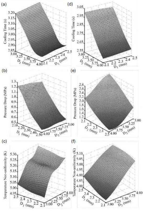
Figure 16.
Predicted performance maps for CCC1 obtained from neural network: (a) cooling time, (b) pressure drop, (c) temperature nonuniformity; and for CCC2 (d) cooling time, (e) pressure drop, (f) temperature nonuniformity. Obtained from [55].
Then, the multiobjective optimization procedure uses a genetic algorithm to optimize the cooling time, pressure drop, and temperature nonuniformity objective functions simultaneously, taking into account their trade-offs. The performance maps generated by the neural network and interpolation-based methods, as mentioned, are employed to create and feed the genetic algorithm with an initial population. The Pareto frontier, on the other hand, is employed to identify the trade-off points between the objectives, as shown in Figure 17, which are then used to select the D2/D1 ratio according to the optimal trade-off point based on the decision-maker’s defined weights (relative importance) for each objective function using the weighted-sum model. Finally, Kanbur et al. [55] observed that both neural network structures had strong agreement with the Pareto frontier results of MATLAB interpolation for a 33% weight on each objective, indicating that the ratio D2/D1 relative error between the neural network approach and the classical interpolation approach is smaller than 1.1%, which led them to conclude that this approach can significantly reduce computational time while achieving high accuracy in performance maps and trade-off point calculations.
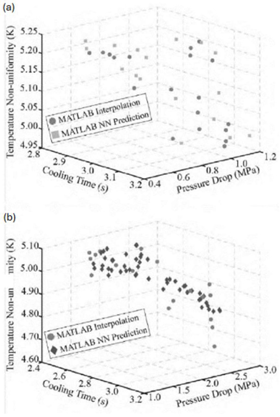
Figure 17.
Pareto frontiers of (a) CCC1 and (b) CCC2. Obtained from [55].
A two-stage multiobjective optimization approach was also proposed by Feng et al. [56], focusing on improving topics such as warpage, weld line, and clamp force. The first stage was used to employ the Taguchi method for design of experiments (DOE), while the second stage employed a hybrid approach combining an artificial neural network (ANN) and multiobjective GA. Multiobjective optimization of CCC performed in MATLAB using the genetic algorithm (GA) was also worked by Shen et al. [57] to generate a Pareto frontier, identifying optimal trade-off points for minimizing pressure drop, uneven temperature, and cooling time. In another work, Park et al. [58] introduced a promising approach for improving the efficiency of additively manufactured CCC via selective laser sintering (SLS) by employing coupled analytical formulations and CAE simulations to create optimal cooling channels that balance cooling performance and manufacturability. Dang [59] introduced two robust optimization frameworks for improving injection molding parameters, including melt and mold temperatures, filling and packing times, and packing pressure. These frameworks included direct numerical optimization and metamodel-based optimization in order to improve defined objective functions, such as warpage, stress, and time to freeze. Hanid et al. [60] aimed to improve the quality of the molded part by defining warpage minimization as the objective function, employing the response surface method (RSM), glowworm swarm optimization (GSO), and genetic algorithm (GA) approaches for both straight drilled and CCC molds. Lin [61] developed an abductive network to predict warpage when defining different parameters for a cooling system, including cooling channel diameter, cooling channel distance, and cooling line equations. From this warpage prediction, the simulated annealing (SA) optimization algorithm was employed to determine the optimal configuration of the cooling system to obtain perfect parts.
Apart from the mentioned approaches, machine learning (ML) has also been employed to optimize cooling system efficiency for injection molding. Machine learning is characterized by a collection of techniques created to automatically identify data patterns aiming at predicting future data or making decisions based on these detected data patterns, working as a subset of artificial intelligence that has gained significant research attention in recent years [62]. For instance, Gao et al. [62] proposed a machine learning-aided conformal cooling design (MLACCD) method for injection molding. The main goal of this method was to provide a global optimal cooling channel distribution for parts with significant and continuous thickness variations. The authors argue that conventional cooling channels are limited in their ability to provide uniform cooling efficiency along the part surface due to variations in part thickness values. Keeping this in mind, the proposed MLACCD method surpasses this limitation by using machine learning techniques to comprehensively explore the design space and create cooling systems that are able to adapt to the part surface, taking into account the part’s thickness distribution, which means that CCC will be located closer or further away from the part according to its thickness. The MLACCD method, as shown in Figure 18, consists of three main activities: preliminary design, ML-aided temperature prediction, and temperature variance minimization (TVM) process. During the preliminary design stage, various cooling channel types—such as zig-zag, spiral, and porous—are considered based on their common use in conformal cooling designs. The design parameters for each cooling channel topology are used to create training datasets for the machine learning model, which predicts the temperature on the part surface in the TVM process and defines the cooling efficiency variation direction (CEVD). Then, the part’s cooling surface is segmented into three different zones based on the part’s thickness contour, where the most appropriate type of cooling channel is assigned to each zone.
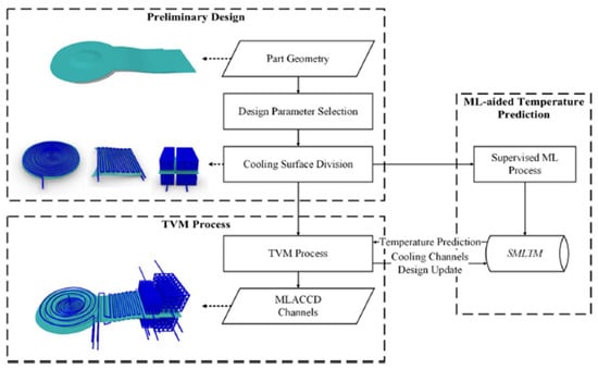
Figure 18.
General design flow of MLACCD cooling channels. Obtained from [62].
In the ML-aided temperature prediction stage, a supervised machine learning method using artificial neural networks (ANN) is employed to train a temperature prediction model, resulting in a supervised machine learning temperature model (SMLTM). This trained surrogate model serves as a rapid temperature prediction tool that interacts with the temperature variance minimization (TVM) process, providing temperature values whenever the cooling channel designs are updated. The ML temperature prediction enables a comprehensive search and optimization of the cooling channel design parameters based on the TVM algorithms, aimed at reducing the part temperature variance. In the TVM process, the part surface temperature variance is minimized using the temperature surrogate model, with optimization algorithms applied to each cooling topology individually. For instance, a four-step design process occurs for TVM spiral cooling channels: 1—control lines are generated; 2—spiral W-optimized control points (WOCP) are established; 3—the WOCP are then transformed into a spiral configuration; 4—adjustments are made to the control line to accommodate the spiral WOCP. This process is supported by a supervised machine learning temperature model (SMLTM), which is acquired for each conformal cooling channel design through the application of the supervised machine learning process.
In their work, a case study was performed for designing cooling channels for a shoe sole with a curved surface, depicted in Figure 19i. The cooling performance was assessed using Autodesk Moldflow Advisor simulations, with input parameters (such as mold material, initial mold temperature, part material, melt temperature, coolant type, coolant inlet temperature, average coolant flow rate, and injection cycle time) for these simulations previously defined. For this particular design case, the zig-zag cooling channel topology was chosen based on the sole’s thickness distribution, as illustrated in Figure 19a,b, where it is observed that conventional CCC (Figure 19b) only takes into account the geometry of the sole (leading to a uniform pattern along geometry), while the MLACCD cooling channel (Figure 19a) also takes into account its thickness (leading to distance variations between the cooling channel and the part surface and the pattern along geometry). Figure 19c–f presents the simulation results from Moldflow, displaying the temperature of the part’s surface and its variation, where it is observed that the implementation of MLACCD cooling channels resulted in a significant reduction in temperature variation across the part’s surface when compared to conventional conformal cooling channels. In addition, a coolant pressure drop was also observed in MLACCD when compared to conventional cooling channels, as illustrated in Figure 19g,f. The authors argue that this approach is more efficient and effective than traditional optimization methods, which rely on manual design and evaluation. The benefits of conformal cooling using this approach are significant; the authors report that the MLACCD method was able to minimize the cooling time by up to 50% and improve the part quality by reducing the warpage and shrinkage. They also report that the MLACCD method was able to generate cooling channel designs that were more robust to variations in part thickness values compared to traditional methods. Overall, the authors argue that the MLACCD method has the potential to significantly improve production efficiency and part quality in the injection molding process.
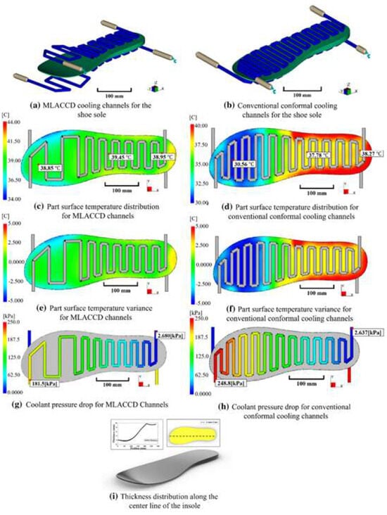
Figure 19.
Comparison of (a) MLACCD and (b) conventional CC for shoe sole. Obtained from [62].
The work carried out by Au et al. [63] refers to developing a variable radius conformal cooling channel (VRCCC) from a 6 mm to 8 mm diameter for Rapid Tool and compare its cooling performance with CCC containing a constant 6 mm diameter. Employing solid freeform fabrication (SFF), the VRCCC was created with a curvilinear shape and variable diameters along the cooling configuration axis to enhance cooling efficiency, as shown in Figure 20.
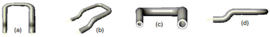
Figure 20.
VRCCC shape with its central axis (a) top view, (b) isometric view, (c) front view, and (d) side view. Obtained from [63].
For that, the authors outline the design methodology for the VRCCC, which consists of three steps: the first step aims to determine the location of the VRCCC using a normal offset from a given cavity surface; the second step focuses on defining the VRCCC variable diameter settings and the layout (path) of the passageway from the inlet to the outlet; and the third—and final—step includes modeling with nonlinear sweeping and shelling operations, followed by fabrication using SFF technologies. The process is shown in Figure 21.
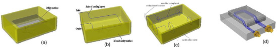
Figure 21.
(a) Offset from cavity surface, (b) cooling configuration central axis, (c) variable diameter along the central axis; and (d) rapid tool modeling with VRCCC. Obtained from [63].
The authors discuss the use of thermal-FEA (with COMSOS/Works 6.0) and melt flow (with Moldflow) analysis to investigate the cooling and heat transfer performances. Firstly, the box is modeled in SolidWorks 2003 and then sent to COMSOS/Works 6.0 to evaluate the influence of the temperature induced stress, which has shown significant deformation along the box’s side edges due to the accumulation of thermal stress, where heat dissipation was inefficient in the cooling stage. Then, a melt flow analysis was performed in Moldflow to investigate the cooling performance of VRCCC and CCC, as shown in Figure 22, and except from the diameter of the channel, all the other parameters (such as flow rate, coolant temperature) were held the same in both simulations. The results revealed a better heat transfer efficiency for the VRCCC than for the CCC, with the minimum temperature observed in the mold using VRCCC 78.3 °C versus 91.22 °C with CCC, and the maximum temperature with VRCCC 126.4 °C versus 150.9 °C with CCC. Thus, the variation in the average temperature was reduced by 24% by implementing VCRRR instead of CCC, which also led to better part quality.
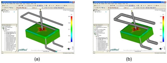
Figure 22.
Cooling performance (average temperature of the part) for (a) CCC and (b) VRCCC. Obtained from [63].
The work carried out by Kuo et al. [64] investigated the effect of the distance between conformal cooling channels and the surface of the mold on part cooling time in rapid injection molds, as well as the effect of CCC roughness on the cooling time. The study was carried out with conformal cooling channels with a fixed diameter of 8 mm, injection molds with twelve different configurations for low-pressure wax injection molding were fabricated and evaluated, dividing the work into two parts: first, six different configurations with different distances between the CCC centerline and the mold cavity (6 mm, 8 mm, 10 mm, 12 mm, 14 mm, and 16 mm) were evaluated (see Figure 4 in Kuo et al. [64]); then, six injection molds with different surface roughnesses on the CCC were evaluated (layer height of 0.3 mm, 0.25 mm, 0.2 mm, 0.15 mm, 0.1 mm, and 0.05 mm), corresponding to maximum surface roughness (Rmax) values of approximately 140 μm, 127 μm, 115 μm, 78 μm, 70 μm, and 58 μm, respectively (see Figure 3 in Kuo et al. [64]). For that, the authors used SolidWorks to design the different studied configurations.
In the first study, Moldex3D (R14 SP3OR, CoreTech System Inc., Zhubei City, Taiwan) simulation software was used to investigate results of the different CCC molds with different center distances from the CC and mold cavity, such as the filling time of the mold (see Figure 5 in Kuo et al. [64]), the cooling time of the molded parts to reach the demolding (ejection) temperature of 30 °C (see Figure 8 in Kuo et al. [64]), the mold temperature difference (see Figure 14 in Kuo et al. [64]), and the part temperature difference (see Figure 12 in Kuo et al. [64]). From the results observed in Moldex3D, it was observed that the cavity filled in 3.629 s and no significant difference in the part and mold temperature variations were identified when using CCC with different distances to the mold surface. However, the cooling time was observed to be affected by this distance, and it was concluded that the part cooling time (y) could be predicted from the center distance with respect to the mold cavity (x) according to the trend equation of y = 141.49 ln (x) + 733.03 (see Figure 9 in Kuo et al. [64]).
From that, it was concluded that a shorter distance between the CCC centerline and the mold cavity resulted in reduced cooling times. Thus, the optimal distance between the CCC centerline and the mold surface was found to be 6 mm, corresponding to a distance of 2 mm between the CCC wall and the mold surface (since CCC radius is 4 mm). Posteriorly, the simulated results concerning the cooling time were compared to the results obtained experimentally (see Figure 12 in Kuo et al. [64]). A relative error on the performed comparison was observed, which could be explained by two possible reasons: the ambient temperature in the experiment was variable while it was fixed in the simulation, which could have affected the results; and the position accuracy of the CCC in the experimental injection mold is inferior to the accuracy when designing in a CAD software, which could have led to results differences.
Concerning the results of the CCC with different surface roughnesses, it was observed that it directly affects the cooling time of the molded part. The Reynolds number of the flow for these studies was 4863, leading to a turbulent flow (see Figure 20 in Kuo et al. [64]), where it was observed that the surface roughness and cooling time were directly related for turbulent flows since increasing the surface roughness led to an increased cooling time. It was found that, under fully turbulent flow conditions, the cooling channel wall’s surface roughness should be minimized because greater surface roughness has been shown to result in higher cooling times in this scenario [64].
Tang et al. [65] made a study for optimizing the diameter of the cooling channel in multicavity injection molding by defining two objective functions: minimizing the temperature gradient throughout all cavities and reducing the molded part average temperature. This work presented a framework for designing efficient cooling systems for multicavity injection molds using computer-aided tools through a procedure that combines the utilization of finite element analysis (FEA) and an optimization solution method, as shown in Figure 23. The optimization code works in conjunction with the FEA code in order to determine the ideal cooling channel parameters, such as diameter, locations, and coolant flow rate, that fulfill the given design objectives. With that, several simulations are conducted to identify the ideal combination of these parameters to minimize the objective functions while ensuring that design constraints are met, iteratively executing this process until the optimum layout is reached (each simulation runs until melt temperature is below ejection temperature and the temperature distribution is analyzed on the surface between mold and part). The optimization procedure employed Powell’s conjugate direction technique along with a penalty function method and with a matrix-free Jacobi Conjugate gradient algorithm based on the Galerkin finite element method for cooling analysis and the results obtained from this optimization showed significant improvements such as the increase in uniformity in temperature distribution.
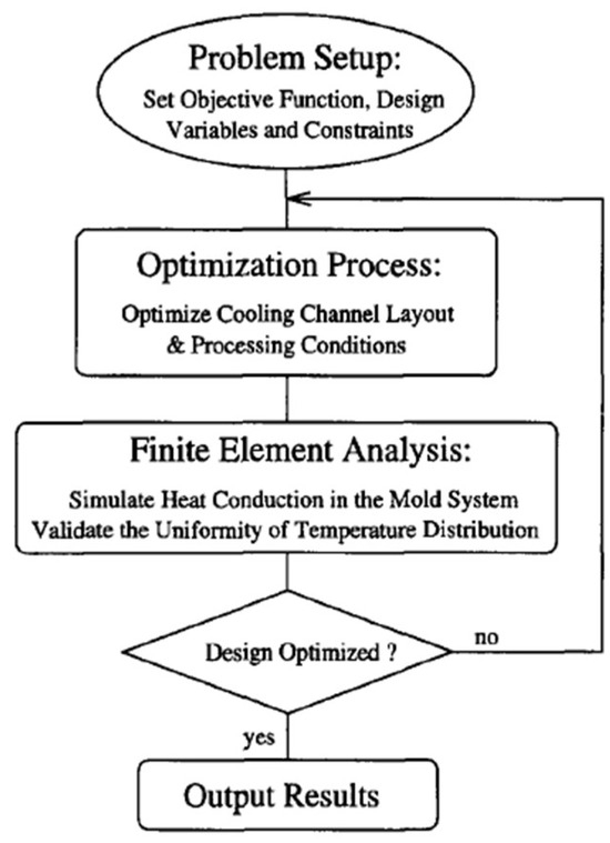
Figure 23.
Schematic of cooling system design framework. Obtained from [65].
Park and Pham [31] proposed a systematic method to design CCC in molds for an automotive part (see Figure 4 in Park and Pham [31]) that could lead to a more efficient and uniform cooling by segmenting the surface of the mold into different zones based on the temperature distribution and defining different CCC design parameters for each zone. The work consisted of using Moldflow software to perform numerical simulations of the filling stage and thermal analysis, proceeding to an optimization process in Matlab to reach the minimum cooling time. For that, a Matlab program was developed to calculate the optimization, where the objective function of the optimized process was stated as the minimization of cooling time (the optimization process is performed for each zone individually) and the design variables were the cooling channel diameter and location. According to the results on temperature distribution obtained from Moldflow after the filling stage, the mold surface was divided into different zones and the CC from each zone were posteriorly all combined to create a unique entire CCC system. The optimization process is illustrated in Figure 24.
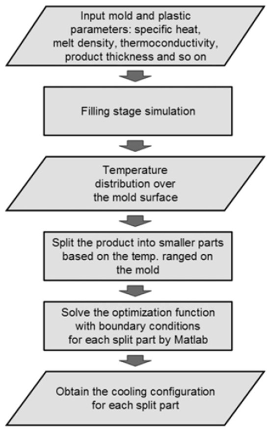
Figure 24.
Optimization process for each conformal cooling subsystem. Obtained from [31].
During the thermal analysis performed after the filling stage (see Figure 5 in Park and Pham [31]), the maximum and minimum mold wall temperatures were observed as 266 °C and 260 °C, respectively, and the mold was split into three zones (left, middle, and right parts) according to a specified temperature range. The left and right parts of the mold were observed to be in the same temperature range (from 260–263 °C); thus, they obtained the same CCC configuration, while the middle part was observed to have a higher temperature range (263–266 °C); thus, a different CCC configuration was applied. From that, the optimization process was performed for both temperature range zones using the same input parameters except the average mold wall temperature. In the zones with a lower temperature range, an average temperature of 261.5 °C was acknowledged, and an average temperature of 264.5 °C was acknowledged for the zone with the higher temperature range. The plotted results of the optimization process for both zones are illustrated in Figure 25, where “t” represents the cooling time, “b” represents the distance between the mold surface and the center of the cooling channel, and “a” represents the distance between two cooling channels. The CC diameters studied varied from 12 mm to 6 mm.
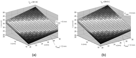
Figure 25.
Effect of cooling configurations on the cooling time for (a) zone with lower temperature range and (b) higher temperature range. Adapted from [31].
The CCC form defined for this mold was a spiral, as shown in Figure 26, and since the objective was to obtain uniform cooling while reducing the cooling time, both zones’ design parameters were defined independently, aiming to converge on the cooling time. The whole CCC was defined with an 8 mm diameter “d” and 10 mm distance from the mold surface to the center of the cooling channel “b”, while the zones were defined with different distances between two cooling channels: 20 mm for the zone with a higher average temperature (as detailed in red color in Figure 26) and 22 mm for the zones with a lower average temperature. The cooling time for the side zones was 25.45 s, while the middle zone was 25.94 s.
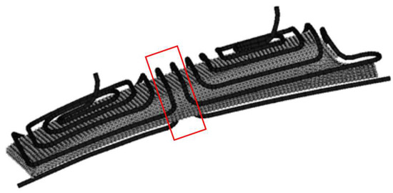
Figure 26.
Spiral cooling configuration, with different configurations for each part of the mold, where red box indicates the mold surface zone with the highest average temperature. Adapted from [31].
Finally, Park and Pham compared the temperature profile and cooling time of the CCC designed through the proposed optimization process with the conventional CC and it was observed that the temperature distribution was improved substantially and the cooling time was enhanced when CCC were employed, with a cooling time for the conventional CC of 35.3 s, while the conformal CC was 25.83 s (see Figure 9 and Figure 10 in Park and Pham [31]).
Simiyu et al. [66] presented an optimization study on conformal cooling channels with different cross-sectional shapes, depths, and pitches in order to reduce the cooling time and reduce product defects such as volumetric shrinkage, warpage, and depth of sink marks. With their work, the authors claimed that the pitch (the distance between two consecutive cooling lines) is the most influential factor affecting cooling time, warpage, shrinkage, and depth of sink marks simultaneously. Jahan et al. [67] proposed a design methodology to optimize conformal cooling channel design variables (such as channel diameter, channel pitch distance, and mold wall to channel centerline distance) where the objective functions were considered as minimizing the cooling time and minimizing the maximum von-Mises stress. For this reason, the authors used the design of experiments (DOE) technique to explore the effects of the design variables and the trade-off technique was employed to identify the best configuration of CCC that would provide the best thermo–mechanical performance of the mold. Kuo et al. [68] used Moldex3D simulation software to assess the performance of profiled conformal cooling channels (PCCC) and circular conformal cooling channels. Their work evaluated parameters such as the cooling time for the molded wax pattern, temperature variations in the part and mold surface, and warpage. The authors concluded that PCCC take advantage over CCCC by providing smaller temperature differences in both the part and the mold surface, as well as shorter cooling times for the wax pattern, which increased the cooling efficiency by 33.33% when PCCC were employed instead of CCCC. Jahan et al. [69] investigated the effect of five different cooling channel cross-sections (circular, square, rectangular, elliptical, and semicircular) in traditional dies for the thermal behavior and cooling performance using ANSYS, and, based on the results, the optimal design was identified. The cooling time prediction simulated by ANSYS showed that the rectangular cross-section proved to be the most effective for the studied die, taking 10.15 s, while the slowest was semicircular and took 13.96 s.
The work carried out by Kariminejad et al. [44] aimed to develop a novel approach for designing and integrating conformal cooling channels into a commercial injection mold tool for a molded part designated “Clip”, which faced design challenges related to a long cycle time and bad quality. To overcome these challenges, the authors used a combination of Moldflow and ANSYS-Fluent modelling tools to simulate the thermal and fluid flow characteristics of the cooling channels as well as to evaluate the efficiency of the CCC in comparison to conventional cooling channels. The methodology adopted in this work involved conducting a series of simulations and analyses using Moldflow and ANSYS-Fluent software, since CFD tools such as ANSYS-Fluent have the ability to simulate the flow of the coolant throughout the cooling channels with high accuracy while also performing analyses of the thermal effects on the mold. Nevertheless, simulating the mold’s temperature distribution and its effects on the part’s cooling time as well as on properties such as residual stress—which affect shrinkage and warpage—can be complex and time-consuming in this type of environment. Therefore, the authors used Moldflow as a complementary analysis tool since it is a CAE software that was developed to accurately and efficiently simulate the different stages of the injection molding process [44].
The performed work followed four main steps, where initially Moldflow was used to simulate and perform thermal analysis to identify component hotspots when using conventional current straight (drilled) cooling channels, as shown in Figure 27. Then, conformal cooling channels were designed in SolidWorks according to the observed hotspots and Clip temperature distribution and then imported into ANSYS-Fluent to simulate the fluid flow through it and evaluate its characteristics (pressure and velocity). Finally, if a designed CCC layout with a satisfactory fluid flow distribution was achieved, the CCC were imported to Moldflow and a thermal analysis was simulated to assess their efficiency and compare the results with the ones observed when using conventional cooling channels. The last three steps (designing CCC in SolidWorks; flow analysis in ANSYS-Fluent; thermal analysis in Moldflow) were repeated until the optimum design was found.

Figure 27.
The 3D meshed molds and conventional cooling channels. Obtained from [44].
In the first step, the initial simulation in Moldflow for the conventional cooling channels allowed hotspots and critical locations of the Clip that led to nonuniform temperature distribution to be identified, as shown in Figure 28, which led to residual stresses and, consequently, shrinkage. This analysis allowed the redesign of the cooling channels in Solidworks according to the observed results and their critical locations, aiming to design a conformal cooling channel layout that could avoid the identified nonuniformity.

Figure 28.
Temperature profile with conventional cooling channels (a) xy cross-section (b) zx cross-section. Obtained from [44].
From the results obtained, the redesigned cooling channels were created in Solidworks and then imported to ANSYS-Fluent to conduct a CFD simulation to evaluate the flow dynamics and distribution in the CCC, where the main goal of this step was to obtain a uniform flow distribution between the branches of the cooling channels and reduce the pressure drop. Based on the fluid flow results, the CCC layout passed through three iterations of modification to achieve optimal flow uniformity and velocity across all branches while also achieving a satisfactory pressure drop. The results of the velocity and pressure drop in the final CCC design are shown in Figure 29 and Figure 30, respectively.
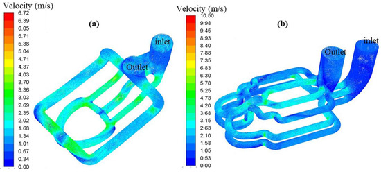
Figure 29.
Simulation results of flow-path lines, colored by velocity in the CCC of the (a) fixed half and (b) moving half of the mold. Obtained from [44].
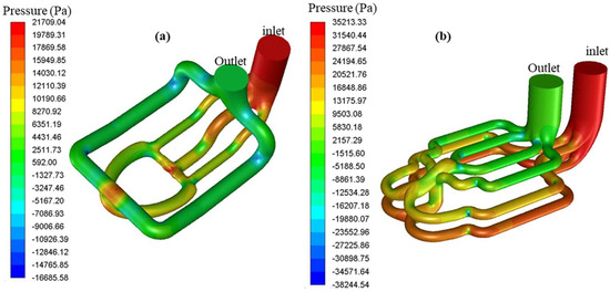
Figure 30.
Simulation results of pressure distribution in the CCC of the (a) fixed half and (b) moving half of the mold. Obtained from [44].
The CFD results from ANSYS-Fluent allowed a relative uniform distribution of the flow in all branches between the inlet and outlet of both fixed and moving halves of the mold to be observed, with an average flow velocity of 3 m/s. Additionally, the pressure distribution in all branches from the inlet to the outlet was also observed to be relatively uniform in both halves, where no substantial localized pressure drop was identified (with an overall pressure drop in the fixed half of 21.7 kPa and of 35.2 kPa in the moving half). From that, this CCC design was then manually imported into Moldflow to perform a thermal analysis. This simulation, as shown in Figure 31, allowed a more uniform temperature distribution in the part to be observed, which confirmed that conformal cooling channels can avoid hotspots and, consequently, improve part cooling and quality. In comparison to conventional cooling channels (shown in Figure 28), where the part temperature varied from 75 °C to 105 °C and had several hotspots with 105 °C, the conformal cooling channel led to a variation of 75 °C to almost 90 °C for most of the regions, reducing the average part temperature from 86.2 °C (conventional CC) to 80.5 °C (conformal CC). In addition, it was observed to have a shorter time to reach ejection temperature, from 19.66 s to 14.42 s.
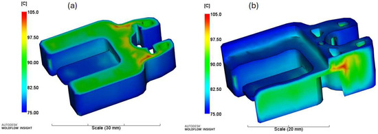
Figure 31.
Temperature profile in the part with CCC at ejection time (a) xy cross-section and (b) zx cross-section. Obtained from [44].
The software employed in this work included Moldflow and ANSYS-Fluent, which work independently and are both computer-aided engineering (CAE) tools that are commonly used in the design and analysis of injection molding processes. Moldflow is specifically designed for simulating the injection molding process with detailed physics phenomena specific to polymer flow and stress analysis, while ANSYS is a more general-purpose CAE tool that can be used for a wide range of engineering simulations, including fluid dynamics and heat transfer. The analyses performed in this work included thermal analysis, fluid flow analysis, and efficiency analysis of the cooling channels. The authors used Moldflow to simulate the filling stage of the injection molding process and calculate the mold temperature distribution while ANSYS-Fluent was used to simulate the fluid flow and pressure drop in the cooling channels, since Fluent has the ability to incorporate more detailed fluid dynamics such as secondary flow [70], flow mixing due to roughness, and flow separation [71], providing a more comprehensive solution compared to Moldflow.
The efficiency of the CCC was evaluated by comparing their thermal performance and overall efficiency to the ones of conventional cooling channels, which led the authors to find out that the use of CCC in injection mold tooling substantially enhances the quality and efficiency of the production process. Performed simulations showed that the CCC provided better cooling and a reduced cycle times compared to conventional cooling channels. The authors also found that the use of Moldflow and ANSYS-Fluent together provided a more comprehensive understanding of the injection molding process and allowed designers to take advantage of the strengths of both tools. In conclusion, this work presents a novel approach for designing and incorporating CCC into a commercial injection mold tool. The use of ANSYS-Fluent allowed to provide further insights into the flow of the coolant through the channel, which led to design optimizations in order to obtain a more uniform and constant flow. On the other hand, Moldflow enabled thermal analysis to be performed on the mold, which also led to the design optimization of the channels in order to obtain a more uniform cooling and, consequently, reduce the cycle time and increase the part quality.
The work carried out by Park and Dang [33] focused on enhancing the cooling system of an existing complex car door module injection mold for an automotive part to improve the molded part quality by reducing the cycle time and solving the observed uneven cooling when using conventional cooling channels. The molded part is complex, with thickness variation along its geometry, which leads to inconsistent cooling times across different regions of the part. From that, initial studies had shown that temperatures in two main regions of the mold were higher than in the rest of the mold, prompting authors to focus their attention on those areas by implementing conformal cooling channels while maintaining conventional cooling channels in the other areas of the mold. To decide the optimal design for the conformal cooling channel, the authors performed a literature review and have studied four types of common conformal cooling channels so that they could implement scaffold, zigzag, spiral, and Voronoi diagrams. Each of these types is appropriate for different cases based on the desired molded part geometry; however, in this case, the authors have concluded that the increase in the cooling circuit distance in the scaffold approach would increase the pressure drop in the coolant flow, which would not sustain the desired turbulent flow. Voronoi, on the other hand, offers more uniform cooling lines around the mold surface, but it would also result in high pressure drops that would lead to uneven coolant velocity (different Reynolds number, which affects the flow type), consequently making it challenging to regulate the rate of heat dissipation. Zigzag would contain a lot of pointless turnings, slowing the coolant flow rate and consequently reducing the cooling efficiency. Finally, the spiral type has been identified as the best approach since it would give a low cooling pressure drop and even Reynolds number throughout the entire system, enabling greater control of the heat removal rate along the cooling channel to be obtained according to its position. The four approaches studied are shown in Figure 32.

Figure 32.
Common types of conformal cooling channels. Obtained from [33].
Due to the geometry of the molded part, the spiral cooling channel was chosen as the most suitable option, and the authors used a combination of analytic and CAE simulation methods to design the conformal cooling channels with Moldflow software. The analytical method was initially employed to estimate the key cooling parameters (such as diameter and the distance between mold surface and center line of the cooling channel), while the simulation with Moldflow was employed for design refinement and result assessment purposes. These simulations allowed the authors to optimize the design of the cooling channels and adjust the distance from the cooling channels to the mold surface until the desired ejection temperature time was achieved. The geometry of the cooling channels was obtained from the CAD model of the mold, as shown in Figure 33, with a channel diameter of 7 mm, a distance between the cooling circuit centers and the mold’s surface of approximately 14 mm, and a distance from the cooling channel centerline to the mold surface of 16 mm.
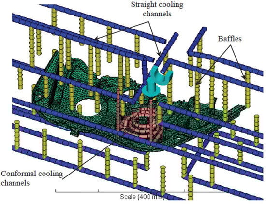
Figure 33.
Local spital conformal cooling channel. Obtained from [33].
The results obtained from the Moldflow simulation showed that conformal cooling channels provided a better temperature distribution in the part than the original cooling channels employed, as shown in Figure 34. The average temperature of the part cooled with CCC decreased significantly, which results in a shorter cooling time, and a lower temperature variation between four different points in the part has also been observed (see Figure 34). This improved even cooling (lower temperature variation) results in lower residual stress and minimized warpage in the molded part, which consequently will lead to a better quality of the final product. These results have confirmed that conformal cooling channels are better than conventional ones.

Figure 34.
Comparison of part temperature distribution: (a) conventional and (b) conformal cooling channels. Obtained from [33].
Additionally, the authors have also studied the effect of the coolant flow rate on the ability to improve cooling. For this purpose, they carried out four different case studies with different inlet coolant flow rates by using Reynolds numbers of 5000, 10,000, 15,000, and 20,000 (which were equivalent to 0.75, 1.5, 2.25, and 3 L/min). The authors collected data from eight different points in the mold and compared the results with the other case studies, and these simulations demonstrated that Reynolds numbers play an important role in how efficient the cooling will be, as shown in Figure 35. The results showed that by increasing the Reynolds number, the cooling is more efficient because the coolant behaves more chaotically (increasing heat transfer), decreasing the observed temperature of the eight points studied and reducing the time to reach the ejection temperature (decreasing the cooling time).

Figure 35.
Temperature distribution for different Reynolds numbers. Obtained from [33].
Finally, a cooling comparison between the molds with conventional cooling channels and conformal cooling channels for a coolant flow rate of 2.25 L/min (Reynolds number = 15,000) was performed, and the results showed a notable reduction in the cooling time, from 39 s to 30 s (approximately 23%), which was a significant improvement. The results were obtained by calculating the average time taken to reach the ejection temperature at 18 different points across the selected region, as illustrated in Figure 36.
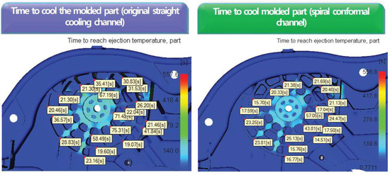
Figure 36.
Comparison of time to reach the ejection temperature. Obtained from [33].
4. Discussion and Limitations
4.1. Overview of CCC Benefits and Implementation
Improvements in the thermal performance enabled by CCC are substantial, and their implementation has been shown to be necessary for the industry. Common issues in the injection molding process that affect parts quality, such as warpage, shrinkage, and surface defects, are significantly mitigated through the use of conformal cooling channels due to the even temperature distribution they provide to the mold. These improvements directly contribute to higher product quality and boost parts productivity. Additionally, as the cooling process becomes faster and thus more efficient, the implementation of CCC also results in energy consumption minimization and a decrease in the overall resources needed for each molding stage. Therefore, cycle time reduction not only improves parts production but also contributes to a more sustainable manufacturing process.
Due to the complexity of the CCC shape and constraints for its manufacturability, additive manufacturing has played an important role in the realization of CCC. Traditional manufacturing methods are constrained in their ability to produce complex, conformal shapes within molds. Three-dimensional printing, on the other hand, has allowed manufacturers to create molds with highly intricate and customized cooling channels that closely follow the geometry of the molded part. The ability to additively manufacture cooling channels in precise and improved shapes enables thermal performance optimization of the molding process, a challenge that was previously unreachable using conventional machining methods. Moreover, additive manufacturing contributes to the overall sustainability of the process by reducing the material waste and energy consumption associated with traditional machining methods.
The flexibility of additive manufacturing to produce different shapes and intricate geometries of conformal cooling channels has also allowed the coolant’s type of flow to be induced and manipulated. Turbulent flow was shown to grant improved results of heat transfer when compared to laminar flow, as the coolant’s chaotic movement raises the mixture of molecules and consequently messes up the well-organized laminar flow structure. As a consequence, this disruption also allows for faster cooling rates and more efficient temperature regulation within the mold.
As a complementary approach to increase heat transfer, the roughness of the CCC surface can also significantly influence fluid dynamics and, thus, heat transfer efficiency within the channel. Rougher surfaces are able to promote turbulence, leading to better heat transfer as the fluid is forced to move in a more chaotic manner. However, achieving the optimal level of turbulence is a challenging task since excessive turbulence can lead to higher pressure drops, which may increase the energy required to circulate the cooling fluid, therefore canceling some of the benefits obtained from improved heat transfer. Thus, additive manufacturing has proven to be a very flexible approach for manufacturing molds with cooling channels, ensuring precise control over the surface finish and offering the ability to produce CCC with the best possible trade-off between heat transfer and pressure drop.
To analyze geometries and thermal performance, CFD has been shown to be an invaluable tool in optimizing CCC. CFD simulations enable engineers to analyze, obtain insights, and predict the behavior of fluid flow and heat transfer within cooling channels before the physical mold is produced. This powerful tool lies in the skill of modeling and replicating real-world conditions, and is among several benefits of using CFD to this end. The ability to test and optimize designs virtually not only saves time and resources but also minimizes material waste and reduces the environmental impact of the manufacturing process. These simulations provide critical insights into the performance of different channel geometries, flow rates, and thermal conditions that allow the industry to optimize CCC designs aimed at maximum efficiency. CFD not only reduces the need for expensive physical prototypes but also allows for rapid iteration and fine-tuning of the mold design. It also helps to identify potential issues, such as areas with poor heat dissipation or excessive pressure drops, before they become problematic in the production environment.
Several approaches have been explored by the academic community, from leveraging advanced CFD techniques to integrating them with machine learning and multiobjective optimization algorithms. The integration of machine learning and CFD simulations enables the analysis of a vast dataset, taking advantage of CFD simulations to identify patterns and correlations that might be difficult to identify through traditional methods. Multiobjective optimization algorithms also played a significant role in several works found in the literature. These algorithms could identify the best trade-off between conflicting objectives, such as maximizing heat transfer while minimizing pressure drop or reducing cycle time without increasing energy consumption. As a result, this approach enables the identification of a Pareto frontier that can be used to support the definition of CCC design parameters.
In addition to flow manipulation and geometrical optimization through CCC, other methods have been explored to improve heat transfer in injection molding. While this review focuses on CCC and their assessment and optimization through CFD, alternative approaches have also garnered attention in the literature. For example, the use of nanofluids shows enhanced thermal performance due to their increased thermal conductivity compared to conventional coolants. Studies indicate that nanofluids can significantly boost cooling rates and promote a more uniform temperature distribution [26,27]. Moreover, techniques like ultrasonic vibration applied to coolant flow can disturb the thermal boundary layer and enhance convective heat transfer [28]. Selecting mold materials with higher thermal conductivity is another relevant strategy, particularly when the geometric optimization of channels is constrained. These methods may be especially useful when CCC implementation is not feasible due to manufacturing, design, or cost-related limitations. Although not explored in detail in this review, they represent valuable complementary solutions that may be integrated with CCC-based strategies in future developments.
4.2. Limitations
This review paper discusses a wide range of studies and methodologies related to the application of CCC and CFD simulations to enhance injection molding cooling efficiency, but several limitations must be considered. The absence of a consistent framework among the various studies makes direct quantitative comparisons challenging. For example, the examined works often differ in key parameters such as cooling channel geometry, coolant types, and other simulation variables.
Additionally, many of the reviewed studies rely on idealized simulation scenarios, overlooking critical manufacturing constraints relevant to real-world industrial contexts. These constraints often pertain to mold fabrication complexity, tolerance issues, and the feasibility of manufacturing the proposed channel paths. Consequently, the lack of experimental validation in some studies limits the confirmation of the proposed channel configurations and their effectiveness. While CFD tools have become reliable and widely used, it remains essential to conduct experimental testing to validate numerical predictions and ensure that all relevant physical behaviors are accurately captured for the studied channel configurations. Insufficient experimental support may render promising numerical results purely theoretical, potentially hindering their translation into practical engineering solutions.
Furthermore, few studies have examined the long-term durability of molds, maintenance implications, or economic feasibility, all of which are crucial for industrial applications. These gaps in the literature highlight valuable directions for future work, ensuring that promising channel configurations identified through CFD simulations can also lead to practical implementation solutions.
5. Conclusions and Future Perspectives
The integration of CCC into injection molding has marked a significant shift in manufacturing by offering innovative possibilities for how we conceive molds and offering distinct advantages over traditional cooling methods. Combined with CFD simulations, CCC design can be evaluated and optimized before mold fabrication, significantly reducing material waste and production costs.
The following main conclusions can be drawn from this literature review:
- CCCs effectively optimize thermal performance, enhance cooling uniformity, reduce cycle times, and improve the overall quality of injection-molded parts;
- CFD is crucial for evaluating and optimizing CCC design, offering insights into thermal behavior, flow characteristics, and mold efficiency before fabrication;
- Flow regime control and surface roughness are key parameters in CCC design, as turbulence improves heat transfer but must be balanced with increased pressure drop and energy costs;
- Additive manufacturing enables the creation of complex CCC geometries unattainable by conventional methods;
- Current challenges include manufacturing constraints and limited experimental validation;
- Further research should investigate the durability and cost-effectiveness of 3D-printed molds, as well as maintenance features.
Looking ahead, the future of CCC in injection molding holds great potential for further innovation and development. As manufacturing processes are in a constant evolution due to technological growth, new opportunities will arise to optimize the design and functionality of CCC. For instance, while conventional metals are still used for mold manufacturing, the future may see the introduction of new materials with superior thermal properties that could enhance the thermal performance of the injection molding process. The exploration of different materials could open new opportunities and ideas for how we design cooling channels and molds as well as focus on sustainability and energy efficiency. From a computational perspective, the future of CCC design for injection molding may involve further AI and machine learning incorporation, developing and training models and datasets able to identify optimal patterns and designs in a faster manner. Additionally, CFD simulations may also involve the development and integration of codes capable of simulating this entire complex process and all rheological phenomena involved in open-source environments, such as OpenFOAM, since almost all the works found in the literature are performed with commercial software, which complicate the exploration of this topic on an academic level.
Author Contributions
Conceptualization, G.W. and J.M.N.; methodology, G.W. and J.M.N.; formal analysis, G.W. and J.M.N.; investigation, G.W.; resources, J.M.N.; writing—original draft preparation, G.W.; writing—review and editing, G.W. and J.M.N.; supervision, J.M.N.; project administration, J.M.N.; funding acquisition, J.M.N. All authors have read and agreed to the published version of the manuscript.
Funding
The authors acknowledge the support of National Funds through FCT-Portuguese Foundation for Science and Technology, projects with reference UID/CTM/50025/2019 and UIDB/04436/2020 and project INOV.AM—INNOVATION IN ADDITIVE MANUFACTURING (PRR/49_ INOV.AM_EE).
Data Availability Statement
The dataset is available on request from the authors.
Conflicts of Interest
The authors declare no conflicts of interest.
References
- Chen, Z.; Turng, L. A review of current developments in process and quality control for injection molding. Adv. Polym. Technol. 2005, 24, 165–182. [Google Scholar] [CrossRef]
- Singh, G.; Verma, A. A Brief Review on injection moulding manufacturing process. Mater. Today Proc. 2017, 4, 1423–1433. [Google Scholar] [CrossRef]
- Khosravani, M.R.; Nasiri, S. Injection molding manufacturing process: Review of case-based reasoning applications. J. Intell. Manuf. 2019, 31, 847–864. [Google Scholar] [CrossRef]
- Zhang, H.; Ren, L.; Gao, Y.; Jin, B. A Comprehensive Study of Energy Conservation in Electric-Hydraulic Injection-Molding Equipment. Energies 2017, 10, 1768. [Google Scholar] [CrossRef]
- Mathivanan, D.; Nouby, M.; Vidhya, R. Minimization of sink mark defects in injection molding process-Taguchi approach. Int. J. Eng. Sci. Technol. 2010, 2, 13–22. [Google Scholar] [CrossRef]
- Fernandes, C.; Pontes, A.J.; Viana, J.C.; Gaspar-Cunha, A. Modeling and Optimization of the Injection-Molding Process: A Review. Adv. Polym. Technol. 2016, 37, 429–449. [Google Scholar] [CrossRef]
- Kashyap, S.; Datta, D. Process parameter optimization of plastic injection molding: A review. Int. J. Plast. Technol. 2015, 19, 1–18. [Google Scholar] [CrossRef]
- Khan, M.; Afaq, S.K.; Khan, N.U.; Ahmad, S. Cycle Time Reduction in Injection Molding Process by Selection of Robust Cooling Channel Design. ISRN Mech. Eng. 2014, 2014, 1–8. [Google Scholar] [CrossRef]
- Hassan, H.; Regnier, N.; Le Bot, C.; Defaye, G. 3D study of cooling system effect on the heat transfer during polymer injection molding. Int. J. Therm. Sci. 2010, 49, 161–169. [Google Scholar] [CrossRef]
- Tan, C.; Wang, D.; Ma, W.; Chen, Y.; Chen, S.; Yang, Y.; Zhou, K. Design and additive manufacturing of novel conformal cooling molds. Mater. Des. 2020, 196, 109147. [Google Scholar] [CrossRef]
- Farouq, Y.; Nicolazo, C.; Sarda, A.; Deterre, R. Temperature measurements in the depth and at the surface of injected thermoplastic parts. Measurement 2005, 38, 1–14. [Google Scholar] [CrossRef]
- Yao, D.; Chen, S.; Kim, B.H. Rapid thermal cycling of injection molds: An overview on technical approaches and applications. Adv. Polym. Technol. 2008, 27, 233–255. [Google Scholar] [CrossRef]
- Shinde, M.S.; Ashtankar, K.M. Additive manufacturing–assisted conformal cooling channels in mold manufacturing processes. Adv. Mech. Eng. 2017, 9, 1687814017699764. [Google Scholar] [CrossRef]
- Kuo, C.-C.; Jiang, Z.-F.; Yang, M.-X.; You, B.J.; Zhong, W.-C. Effects of cooling channel layout on the cooling performance of rapid injection mold. Int. J. Adv. Manuf. Technol. 2021, 114, 2697–2710. [Google Scholar] [CrossRef]
- Hassan, H.; Regnier, N.; Lebot, C.; Pujos, C.; Defaye, G. Effect of cooling system on the polymer temperature and solidification during injection molding. Appl. Therm. Eng. 2009, 29, 1786–1791. [Google Scholar] [CrossRef]
- Fellahi, S.; Meddad, A.; Fisa, B.; Favis, B.D. Weldlines in Injection-Molded Parts: A Review. Adv. Polym. Technol. J. Polym. Process. Inst. 1995, 14, 169–195. [Google Scholar] [CrossRef]
- Li, X.-J.; Zuo, Z.-M.; Mi, H.-Y.; Dong, B.-B.; Antwi-Afari, M.-F.; Liu, C.-T.; Shen, C.-Y. A review of research progress on the minimization of weld lines in injection molding. Int. J. Adv. Manuf. Technol. 2024, 132, 5179–5210. [Google Scholar] [CrossRef]
- Mohan, M.; Ansari, M.; Shanks, R.A. Review on the Effects of Process Parameters on Strength, Shrinkage, and Warpage of Injection Molding Plastic Component. Polym. Technol. Eng. 2016, 56, 1–12. [Google Scholar] [CrossRef]
- Sánchez, R.; Aisa, J.; Martinez, A.; Mercado, D. On the relationship between cooling setup and warpage in injection molding. Measurement 2012, 45, 1051–1056. [Google Scholar] [CrossRef]
- Alves, P.S.F.F. Shrinkage and Warpage Behaviour on Injection Moulding Parts; Universidade do Minho: Braga, Portugal, 2008. [Google Scholar]
- Rahim, S.Z.A.; Sharif, S.; Zain, A.M.; Nasir, S.M.; Saad, R.M. Improving the Quality and Productivity of Molded Parts with a New Design of Conformal Cooling Channels for the Injection Molding Process. Adv. Polym. Technol. 2015, 35, 21524. [Google Scholar] [CrossRef]
- Hassan, H.; Regnier, N.; Pujos, C.; Arquis, E.; Defaye, G. Modeling the effect of cooling system on the shrinkage and temperature of the polymer by injection molding. Appl. Therm. Eng. 2010, 30, 1547–1557. [Google Scholar] [CrossRef]
- Marin, F.; de Miranda, J.R.; de Souza, A.F. Study of the design of cooling channels for polymers injection molds. Polym. Eng. Sci. 2017, 58, 552–559. [Google Scholar] [CrossRef]
- Dimla, D.E.; Camilotto, M.; Miani, F. Design and optimisation of conformal cooling channels in injection moulding tools. J. Mater. Process. Technol. 2005, 164–165, 1294–1300. [Google Scholar] [CrossRef]
- Kanbur, B.B.; Suping, S.; Duan, F. Design and optimization of conformal cooling channels for injection molding: A review. Int. J. Adv. Manuf. Technol. 2020, 106, 3253–3271. [Google Scholar] [CrossRef]
- Nguyen, C.T.; Roy, G.; Gauthier, C.; Galanis, N. Heat transfer enhancement using Al2O3–water nanofluid for an electronic liquid cooling system. Appl. Therm. Eng. 2007, 27, 1501–1506. [Google Scholar] [CrossRef]
- Wongcharee, K.; Eiamsa-Ard, S. Heat transfer enhancement by using CuO/water nanofluid in corrugated tube equipped with twisted tape. Int. Commun. Heat Mass Transf. 2012, 39, 251–257. [Google Scholar] [CrossRef]
- Zhang, D.; Jiang, E.; Zhou, J.; Shen, C.; He, Z.; Xiao, C. Investigation on enhanced mechanism of heat transfer assisted by ultrasonic vibration. Int. Commun. Heat Mass Transf. 2020, 115, 104523. [Google Scholar] [CrossRef]
- Feng, S.; Kamat, A.M.; Pei, Y. Design and fabrication of conformal cooling channels in molds: Review and progress updates. Int. J. Heat Mass Transf. 2021, 171, 121082. [Google Scholar] [CrossRef]
- Guilong, W.; Guoqun, Z.; Huiping, L.; Yanjin, G. Analysis of thermal cycling efficiency and optimal design of heating/cooling systems for rapid heat cycle injection molding process. Mater. Des. 2010, 31, 3426–3441. [Google Scholar] [CrossRef]
- Park, H.S.; Pham, N.H. Design of conformal cooling channels for an automotive part. Int. J. Automot. Technol. 2009, 10, 87–93. [Google Scholar] [CrossRef]
- Tang, S.; Kong, Y.; Sapuan, S.; Samin, R.; Sulaiman, S. Design and thermal analysis of plastic injection mould. J. Mech. Work. Technol. 2006, 171, 259–267. [Google Scholar] [CrossRef]
- Park, H.-S.; Dang, X.-P. Development of a Smart Plastic Injection Mold with Conformal Cooling Channels. Procedia Manuf. 2017, 10, 48–59. [Google Scholar] [CrossRef]
- Franchetti, M.; Kress, C. An economic analysis comparing the cost feasibility of replacing injection molding processes with emerging additive manufacturing techniques. Int. J. Adv. Manuf. Technol. 2016, 88, 2573–2579. [Google Scholar] [CrossRef]
- Hölker, R.; Tekkaya, A.E. Advancements in the manufacturing of dies for hot aluminum extrusion with conformal cooling channels. Int. J. Adv. Manuf. Technol. 2015, 83, 1209–1220. [Google Scholar] [CrossRef]
- Kirchheim, A.; Katrodiya, Y.; Zumofen, L.; Ehrig, F.; Wick, C. Dynamic conformal cooling improves injection molding: Hybrid molds manufactured by laser powder bed fusion. Int. J. Adv. Manuf. Technol. 2021, 114, 107–116. [Google Scholar] [CrossRef]
- Du, W.; Bai, Q.; Zhang, B. A Novel Method for Additive/Subtractive Hybrid Manufacturing of Metallic Parts. Procedia Manuf. 2016, 5, 1018–1030. [Google Scholar] [CrossRef]
- Williams, R.E.; Walczyk, D.F.; Dang, H.T. Using abrasive flow machining to seal and finish conformal channels in laminated tooling. Rapid Prototyp. J. 2007, 13, 64–75. [Google Scholar] [CrossRef]
- Man, A.K. Conformal Cooling Channels Design for Rapid Plastic Injection Mould. PhD Thesis, Hong Kong Polytechnic University, Hong Kong, China, 2008. Available online: https://theses.lib.polyu.edu.hk/handle/200/4807 (accessed on 8 April 2025).
- Hasanpour, A.; Farhadi, M.; Sedighi, K. A review study on twisted tape inserts on turbulent flow heat exchangers: The overall enhancement ratio criteria. Int. Commun. Heat Mass Transf. 2014, 55, 53–62. [Google Scholar] [CrossRef]
- Kang, M.; Hwang, L.K.; Kwon, B. Computationally efficient optimization of wavy surface roughness in cooling channels using simulated annealing. Int. J. Heat Mass Transf. 2020, 150, 119300. [Google Scholar] [CrossRef]
- Kadivar, M.; Tormey, D.; McGranaghan, G. A review on turbulent flow over rough surfaces: Fundamentals and theories. Int. J. Thermofluids 2021, 10, 100077. [Google Scholar] [CrossRef]
- Everts, M.; Robbertse, P.; Spitholt, B. The effects of surface roughness on fully developed laminar and transitional flow friction factors and heat transfer coefficients in horizontal circular tubes. Int. J. Heat Mass Transf. 2022, 189, 122724. [Google Scholar] [CrossRef]
- Kariminejad, M.; Kadivar, M.; McAfee, M.; McGranaghan, G.; Tormey, D. Comparison of Conventional and Conformal Cooling Channels in the Production of a Commercial Injection-Moulded Component. Key Eng. Mater. 2022, 926, 1821–1831. [Google Scholar] [CrossRef]
- Arman, S.; Lazoglu, I. A comprehensive review of injection mold cooling by using conformal cooling channels and thermally enhanced molds. Int. J. Adv. Manuf. Technol. 2023, 127, 2035–2106. [Google Scholar] [CrossRef]
- Mohamed, O.A.; Masood, S.H.; Saifullah, A. A Simulation Study of Conformal Cooling Channels in Plastic Injection Molding. Int. J. Eng. Res. 2017, 5, 99–111. [Google Scholar]
- Purav, A.C.; Singraur, D.S.; Sudhakar, D.S.S. Investigations into performance of conventional and conformal cooling channels of a plastic injection mold. J. Eng. Dev. Res. 2017, 5, 99–111. [Google Scholar] [CrossRef]
- Gloinn, T.; Hayes, C.; Hanniffy, P.; Vaugh, K. FEA simulation of conformal cooling within injection moulds. Int. J. Manuf. Res. 2007, 2, 162–170. [Google Scholar] [CrossRef]
- Kanbur, B.B.; Zhou, Y.; Shen, S.; Wong, K.H.; Chen, C.; Shocket, A.; Duan, F. Metal Additive Manufacturing of Plastic Injection Molds with Conformal Cooling Channels. Polymers 2022, 14, 424. [Google Scholar] [CrossRef]
- Kitayama, S.; Miyakawa, H.; Takano, M.; Aiba, S. Multi-objective optimization of injection molding process parameters for short cycle time and warpage reduction using conformal cooling channel. Int. J. Adv. Manuf. Technol. 2016, 88, 1735–1744. [Google Scholar] [CrossRef]
- Wu, T.; SA, J.; Kumaar, P.; Tovar, A.; El-Mounayri, H.; Zhang, Y.; Zhang, J.; Acheson, D.; Brand, K.; Nalim, R. A Framework for Optimizing the Design of Injection Molds with Conformal Cooling for Additive Manufacturing. Procedia Manuf. 2015, 1, 404–415. [Google Scholar] [CrossRef]
- Wu, T.; Tovar, A. Design for Additive Manufacturing of Conformal Cooling Channels Using Thermal-Fluid Topology Optimization and Application in Injection Molds. In Proceedings of the ASME 2018 International Design Engineering Technical Conferences and Computers and Information in Engineering Conference, Québec, QC, Canada, 26–29 August 2018. [Google Scholar]
- Wang, M.L.; Zheng, L.J.; Bae, S.; Kang, H.W. Comprehensive performance enhancement of conformal cooling process using thermal-load-based topology optimization. Appl. Therm. Eng. 2023, 227, 120332. [Google Scholar] [CrossRef]
- Martowibowo, S.Y.; Kaswadi, A. Optimization and Simulation of Plastic Injection Process using Genetic Algorithm and Moldflow. Chin. J. Mech. Eng. 2017, 30, 398–406. [Google Scholar] [CrossRef]
- Kanbur, B.B.; Shen, S.; Zhou, Y.; Duan, F. Neural network-integrated multiobjective optimization of the 3D-printed conformal cooling channels. In Proceedings of the 2020 5th International Conference on Smart and Sustainable Technologies (SpliTech), Split, Croatia, 23–26 September 2020; pp. 1–6. [Google Scholar]
- Feng, Q.; Liu, L.; Zhou, X. Automated multi-objective optimization for thin-walled plastic products using Taguchi, ANOVA, and hybrid ANN-MOGA. Int. J. Adv. Manuf. Technol. 2019, 106, 559–575. [Google Scholar] [CrossRef]
- Shen, S.; Kanbur, B.B.; Zhou, Y.; Duan, F. Thermal and Mechanical Assessments of the 3D-Printed Conformal Cooling Channels: Computational Analysis and Multi-objective Optimization. J. Mater. Eng. Perform. 2020, 29, 8261–8270. [Google Scholar] [CrossRef]
- Park, H.-S.; Dang, X.-P.; Nguyen, D.-S.; Kumar, S. Design of Advanced Injection Mold to Increase Cooling Efficiency. Int. J. Precis. Eng. Manuf. Technol. 2019, 7, 319–328. [Google Scholar] [CrossRef]
- Dang, X.-P. General frameworks for optimization of plastic injection molding process parameters. Simul. Model. Pr. Theory 2014, 41, 15–27. [Google Scholar] [CrossRef]
- Hanid, M.H.M.; Rahim, S.Z.A.; Gondro, J.; Sharif, S.; Abdullah, M.M.A.B.; Zain, A.M.; Abdellah, A.E.-H.; Saad, M.N.M.; Wysłocki, J.J.; Nabiałek, M. Warpage Optimisation on the Moulded Part with Straight Drilled and Conformal Cooling Channels Using Response Surface Methodology (RSM), Glowworm Swarm Optimisation (GSO) and Genetic Algorithm (GA) Optimisation Approaches. Materials 2021, 14, 1326. [Google Scholar] [CrossRef] [PubMed]
- Lin, J. Optimum cooling system design of a free-form injection mold using an abductive network. J. Mech. Work. Technol. 2001, 120, 226–236. [Google Scholar] [CrossRef]
- Gao, Z.; Dong, G.; Tang, Y.; Zhao, Y.F. Machine learning aided design of conformal cooling channels for injection molding. J. Intell. Manuf. 2021, 34, 1183–1201. [Google Scholar] [CrossRef]
- Au, K.M.; Yu, K.M. Variable Radius Conformal Cooling Channel for Rapid Tool. Mater. Sci. Forum 2006, 532, 520–523. [Google Scholar] [CrossRef]
- Kuo, C.-C.; Jiang, Z.-F.; Lee, J.-H. Effects of cooling time of molded parts on rapid injection molds with different layouts and surface roughness of conformal cooling channels. Int. J. Adv. Manuf. Technol. 2019, 103, 2169–2182. [Google Scholar] [CrossRef]
- Tang, L.Q.; Chassapis, C.; Manoochehri, S. Optimal cooling system design for multi-cavity injection molding. Finite Elements Anal. Des. 1997, 26, 229–251. [Google Scholar] [CrossRef]
- Simiyu, L.W.; Mutua, J.M.; Muiruri, P.I.; Ikua, B.W. Optimization of polygonal cross-sectioned conformal cooling channels in injection molding. Int. J. Interact. Des. Manuf. (IJIDeM) 2023, 18, 1593–1609. [Google Scholar] [CrossRef]
- Jahan, S.A.; Wu, T.; Zhang, Y.; Zhang, J.; Tovar, A.; Elmounayri, H. Thermo-mechanical Design Optimization of Conformal Cooling Channels using Design of Experiments Approach. Procedia Manuf. 2017, 10, 898–911. [Google Scholar] [CrossRef]
- Kuo, C.-C.; Jiang, Z.-F.; Yang, X.-Y.; Chu, S.-X.; Wu, J.-Q. Characterization of a direct metal printed injection mold with different conformal cooling channels. Int. J. Adv. Manuf. Technol. 2020, 107, 1223–1238. [Google Scholar] [CrossRef]
- Jahan, S.A.; El-Mounayri, H. Optimal Conformal Cooling Channels in 3D Printed Dies for Plastic Injection Molding. Procedia Manuf. 2016, 5, 888–900. [Google Scholar] [CrossRef]
- Doshmanziari, F.I.; Kadivar, M.R.; Yaghoubi, M.; Jalali-Vahid, D.; Arvinfar, M.A. Experimental and Numerical Study of Turbulent Fluid Flow and Heat Transfer of Al2O3/Water Nanofluid in a Spiral-Coil Tube. Heat Transf. Eng. 2016, 38, 611–626. [Google Scholar] [CrossRef]
- Ramamurthy, A.S.; Han, S.S.; Biron, P.M. Three-Dimensional Simulation Parameters for 90° Open Channel Bend Flows. J. Comput. Civ. Eng. 2013, 27, 282–291. [Google Scholar] [CrossRef]
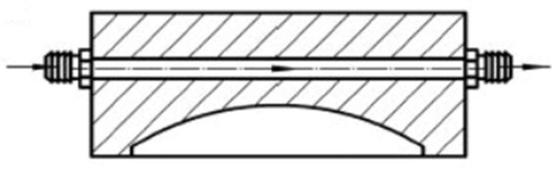
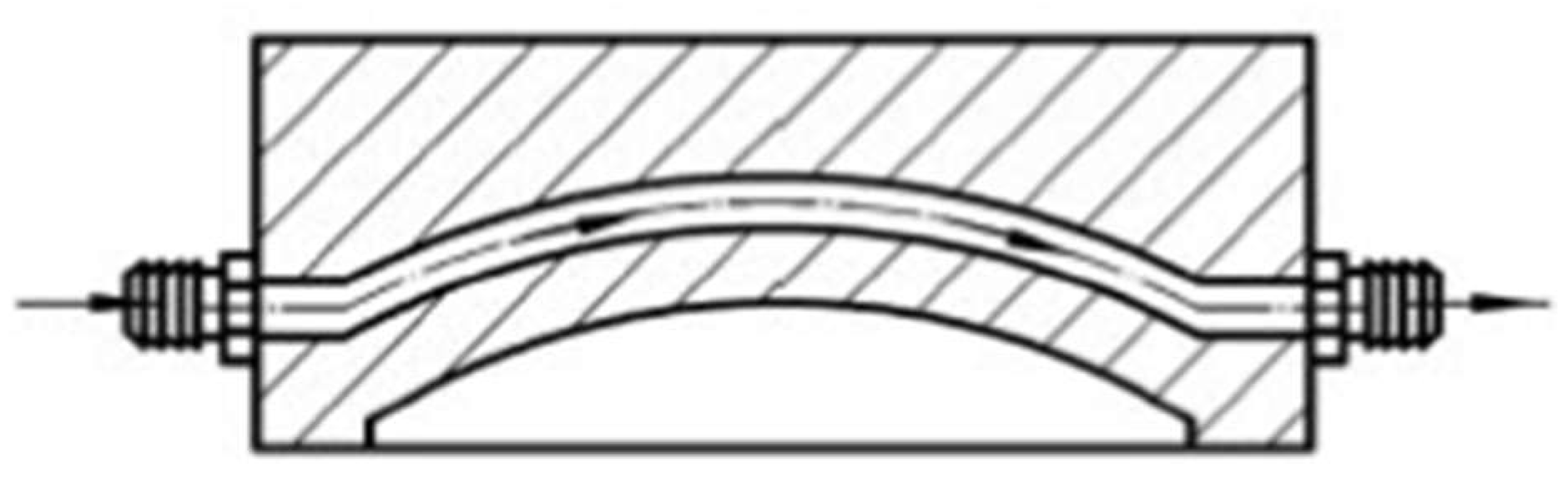


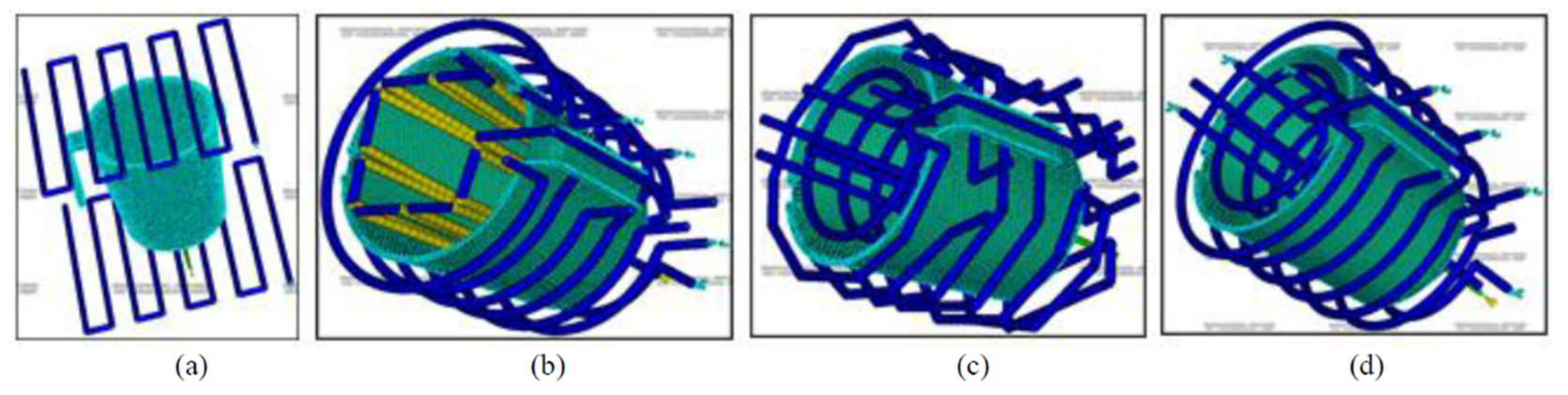
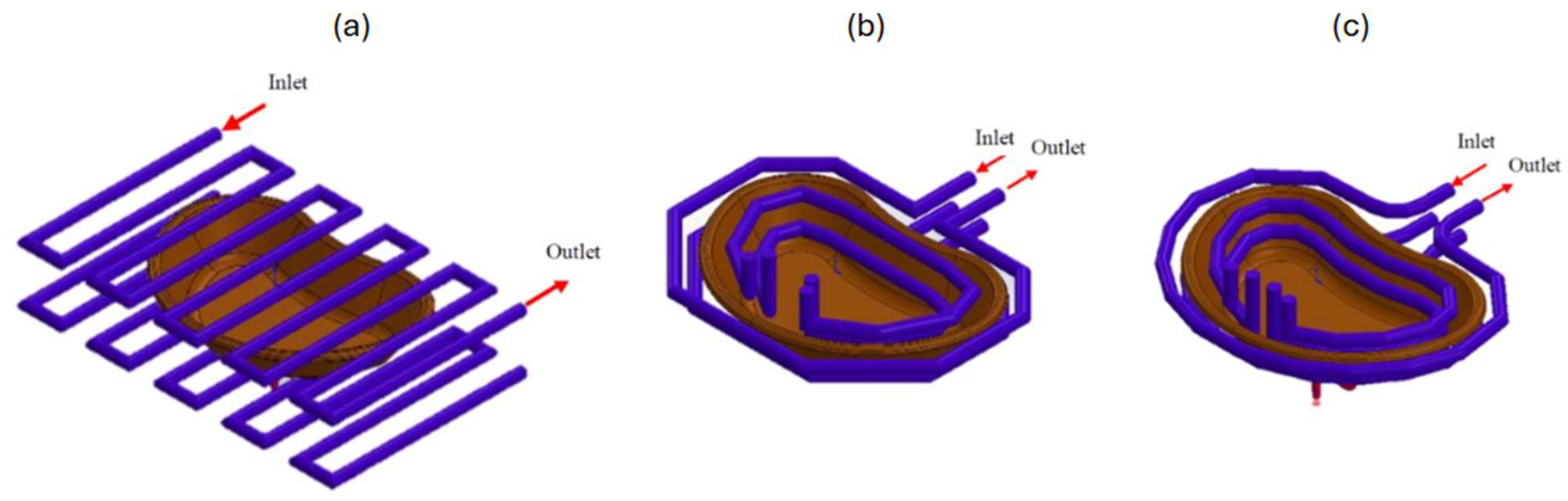

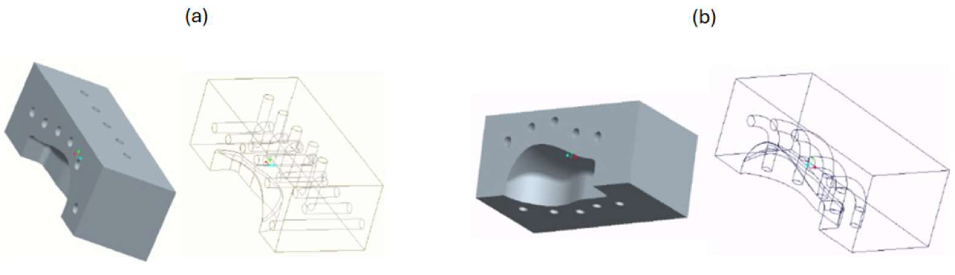
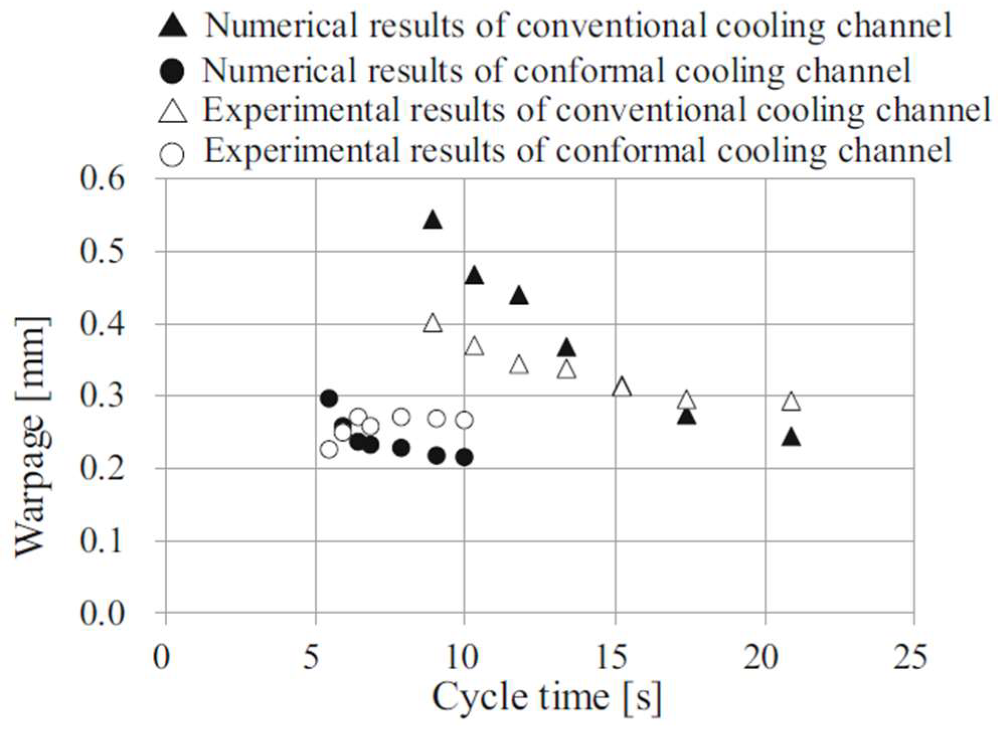

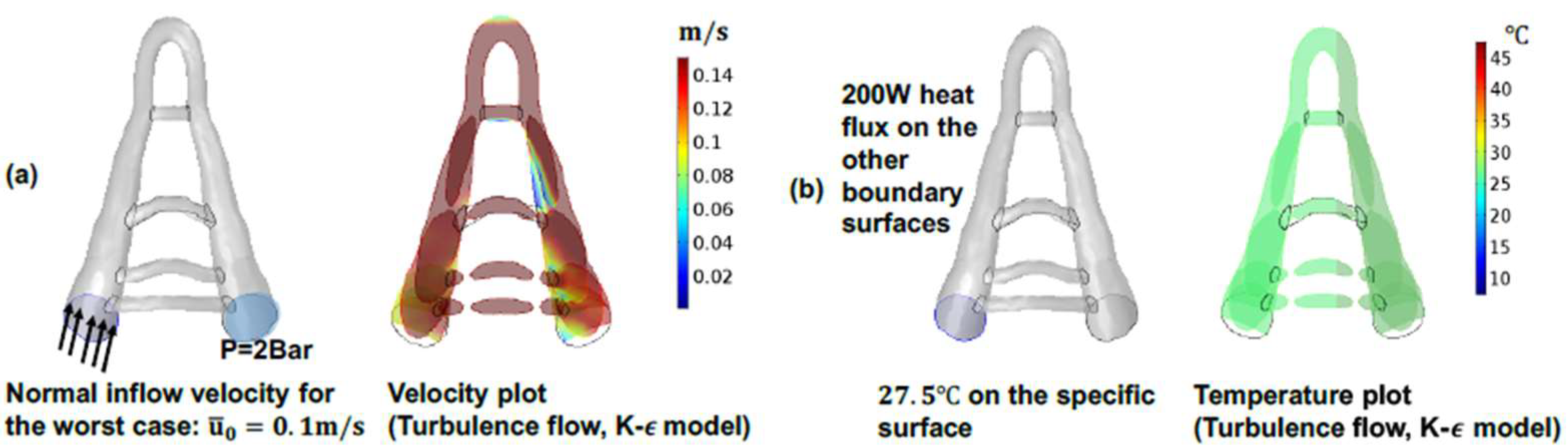
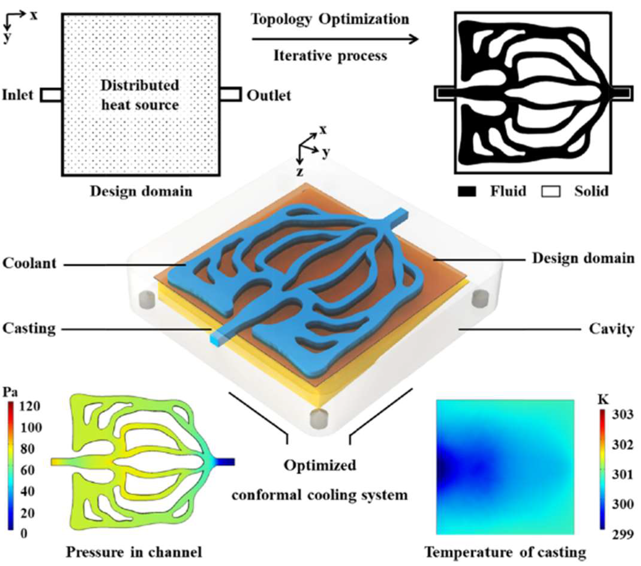

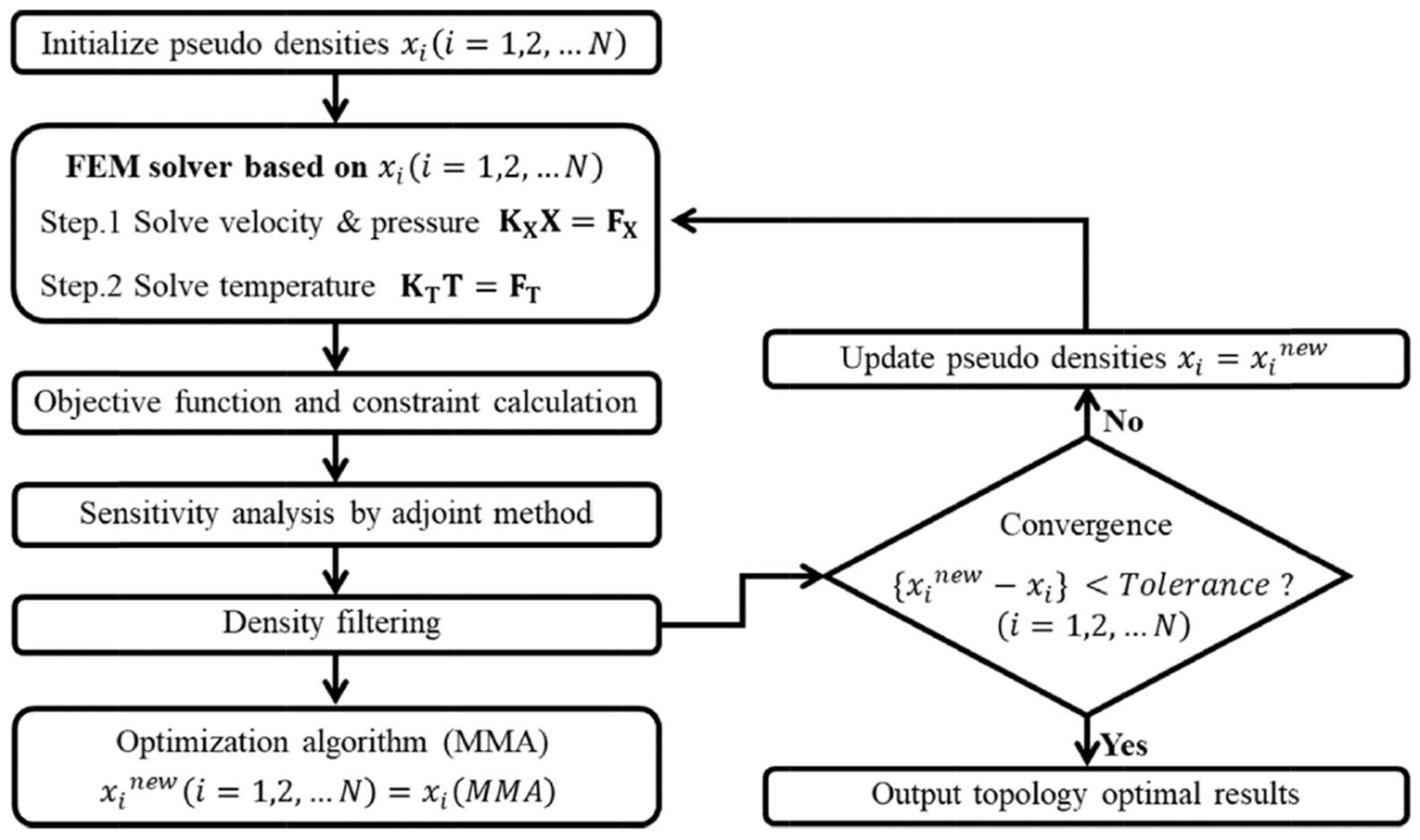
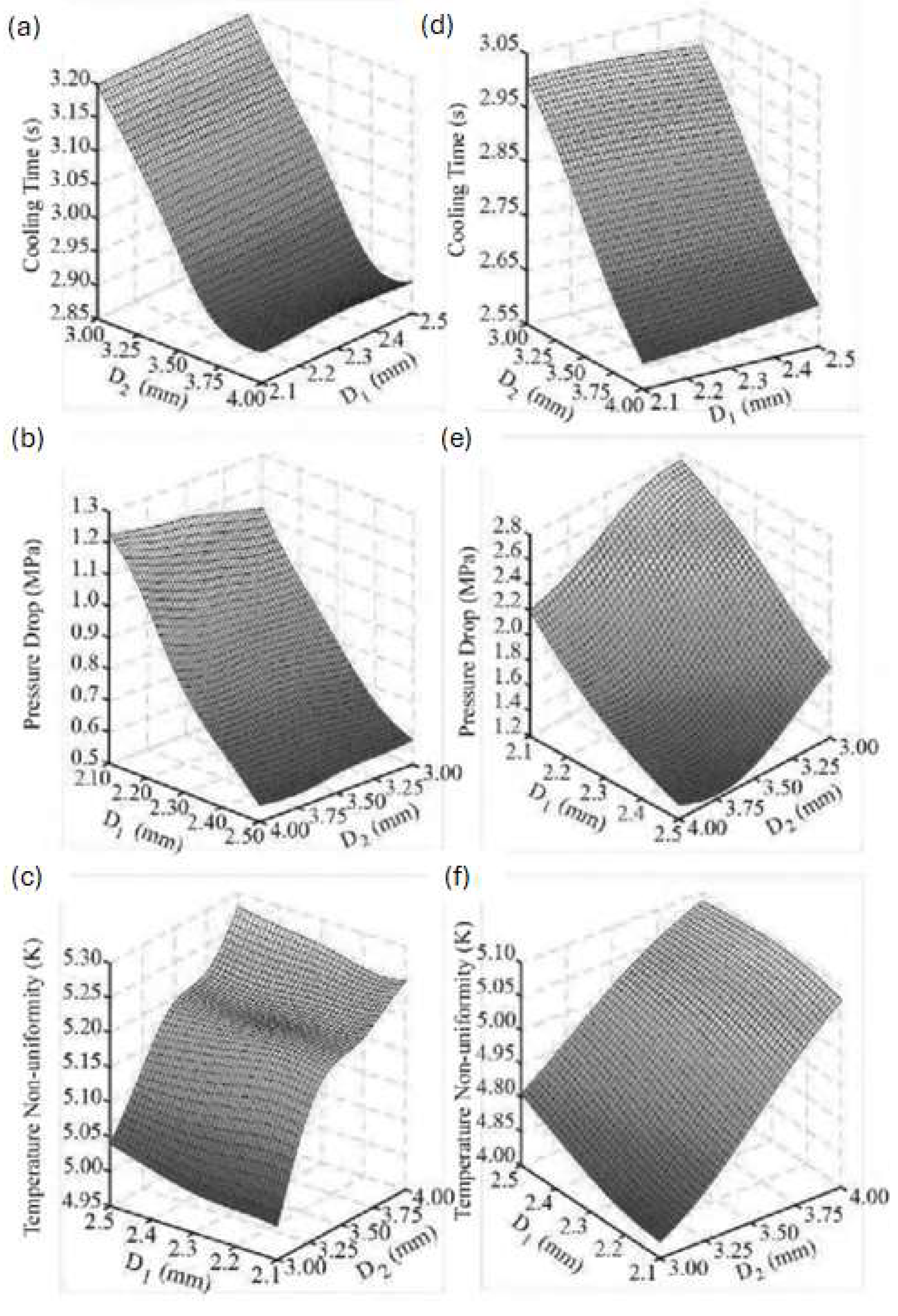
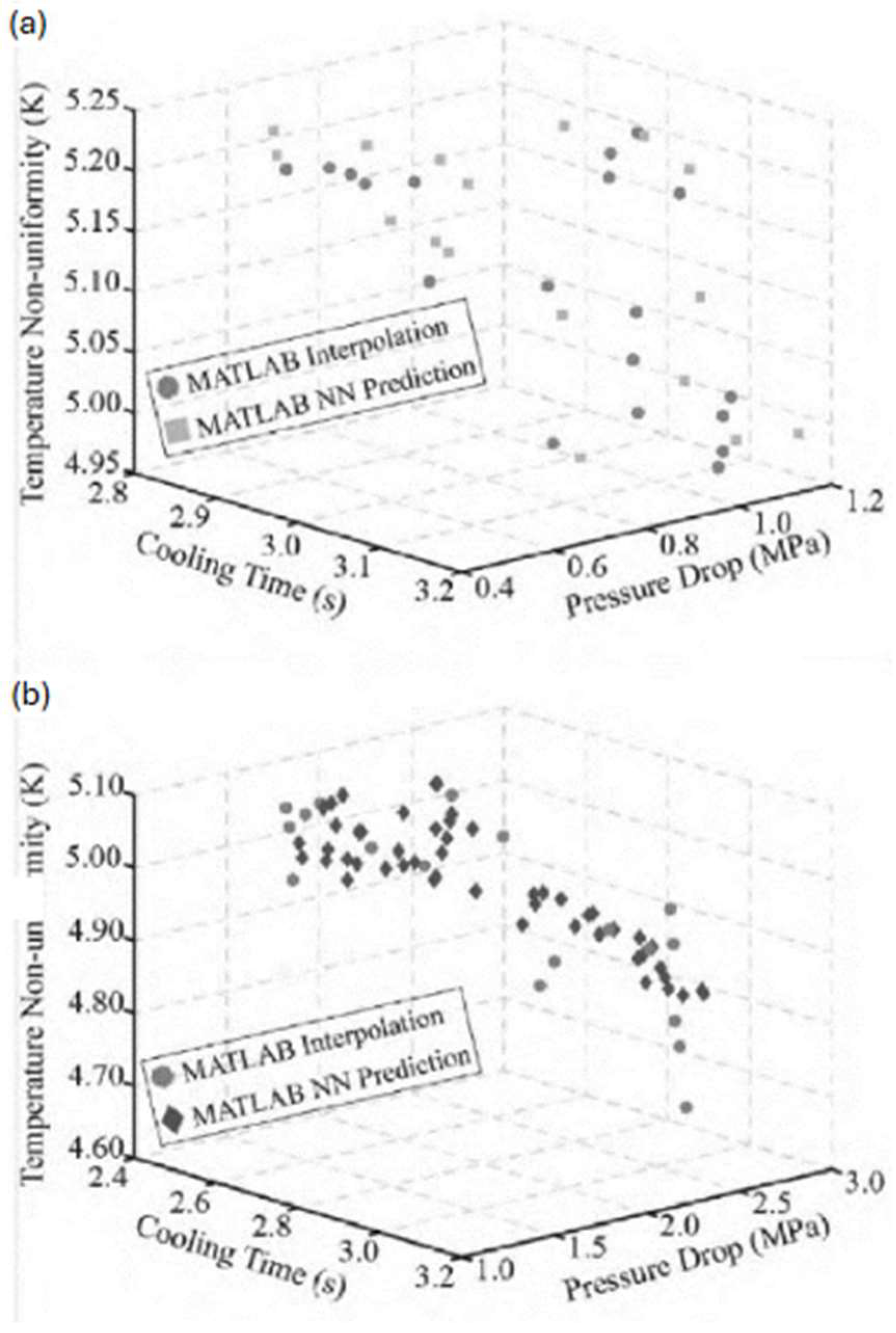

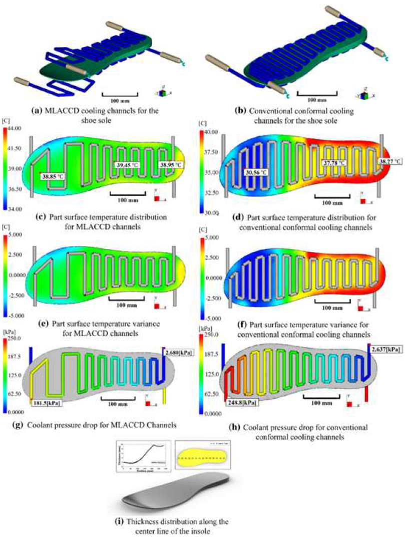
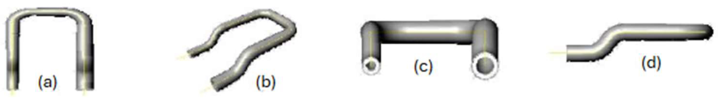

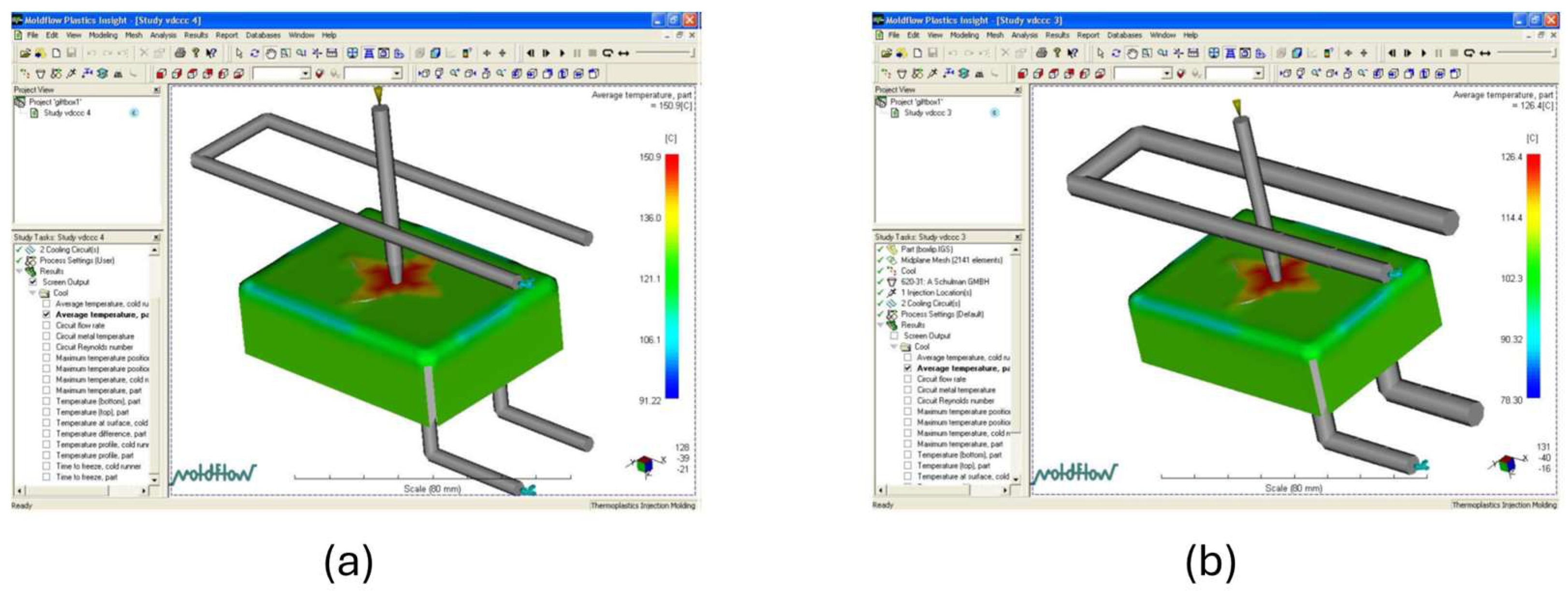

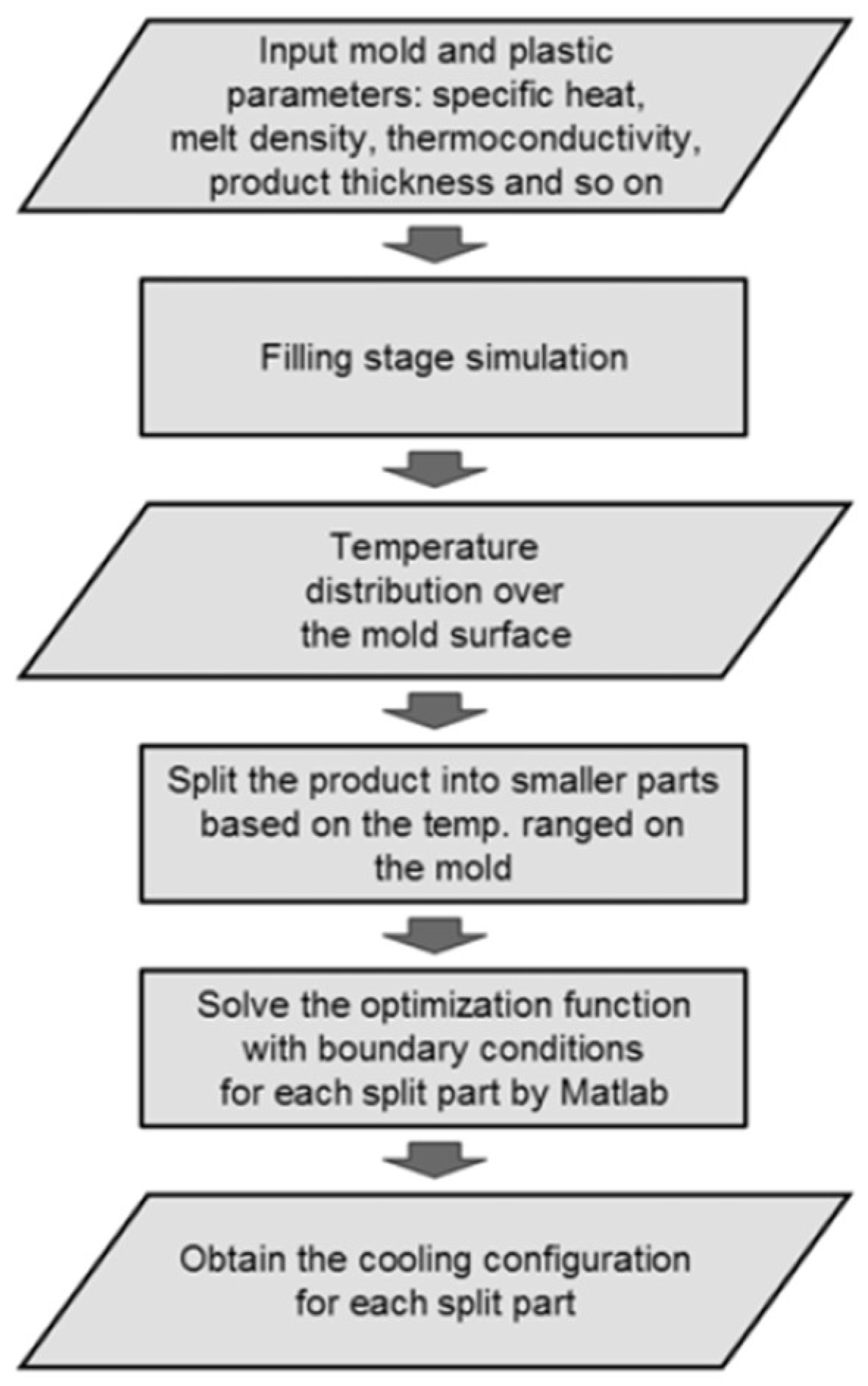

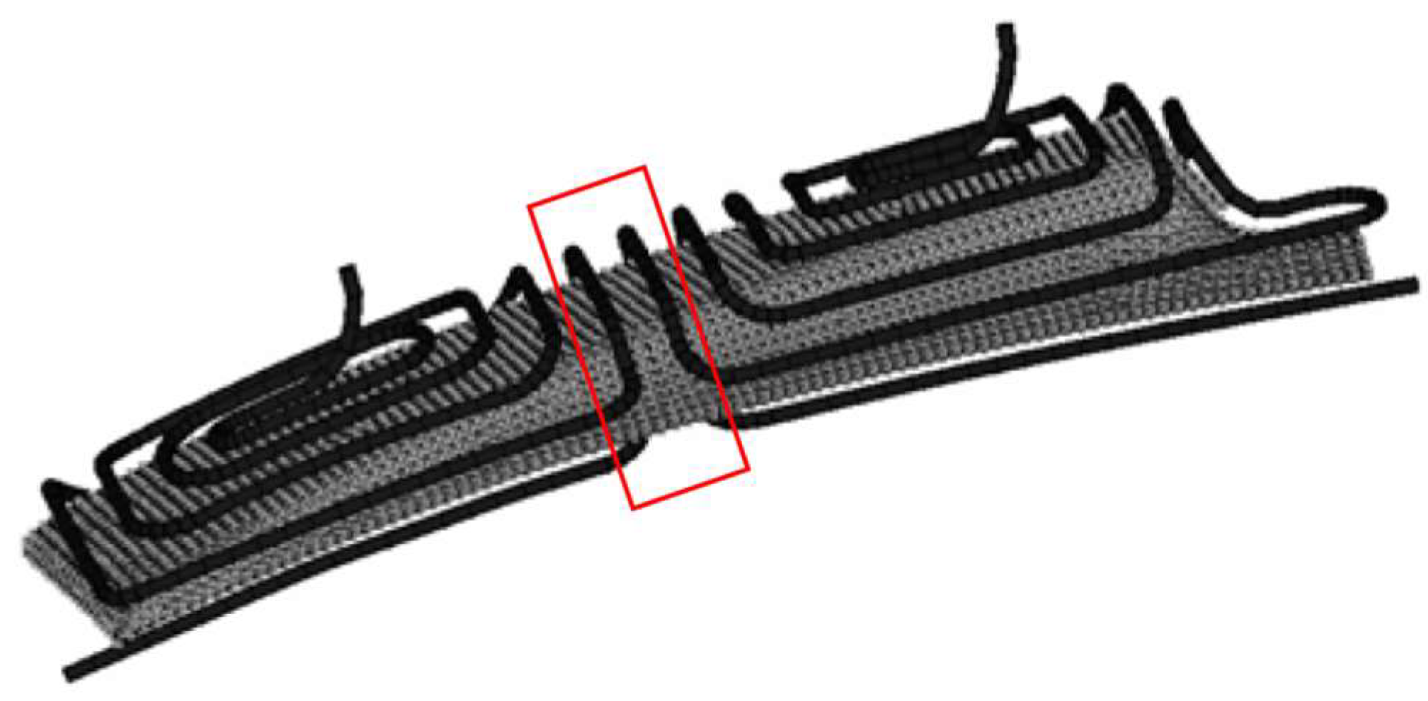
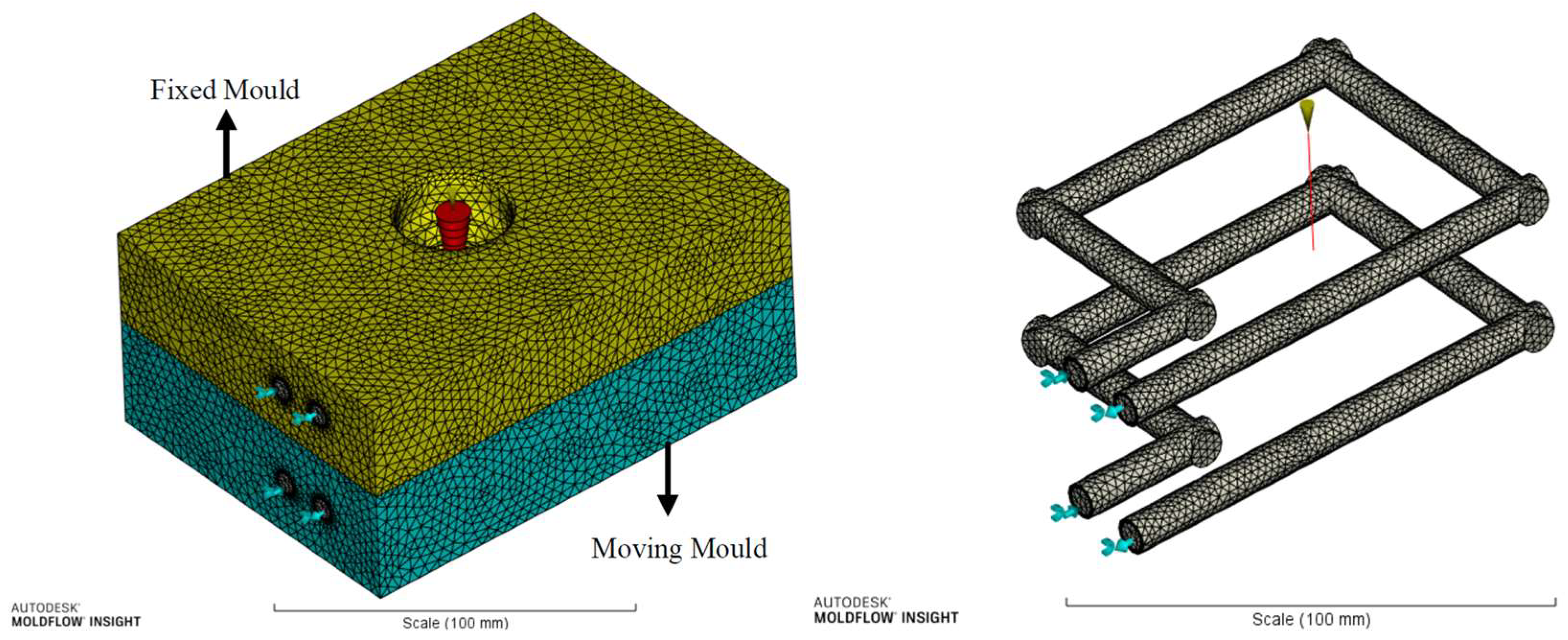
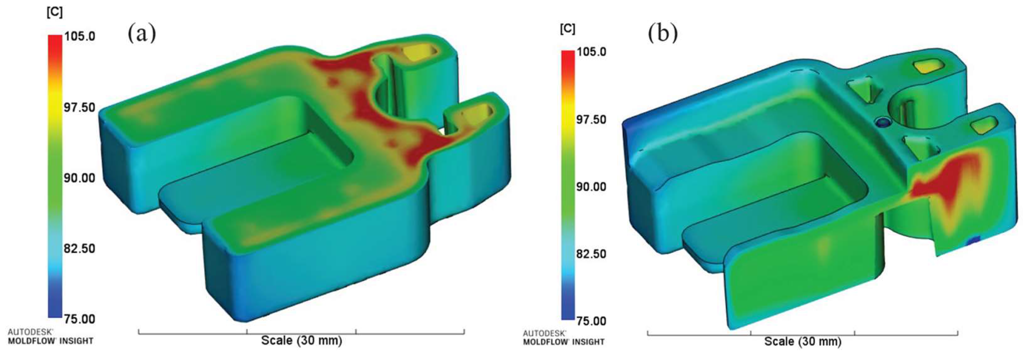
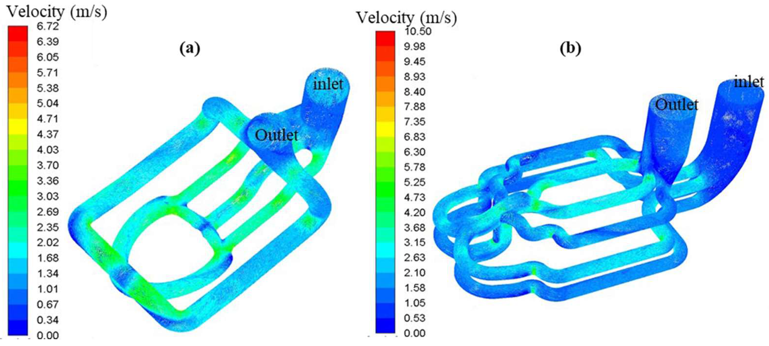


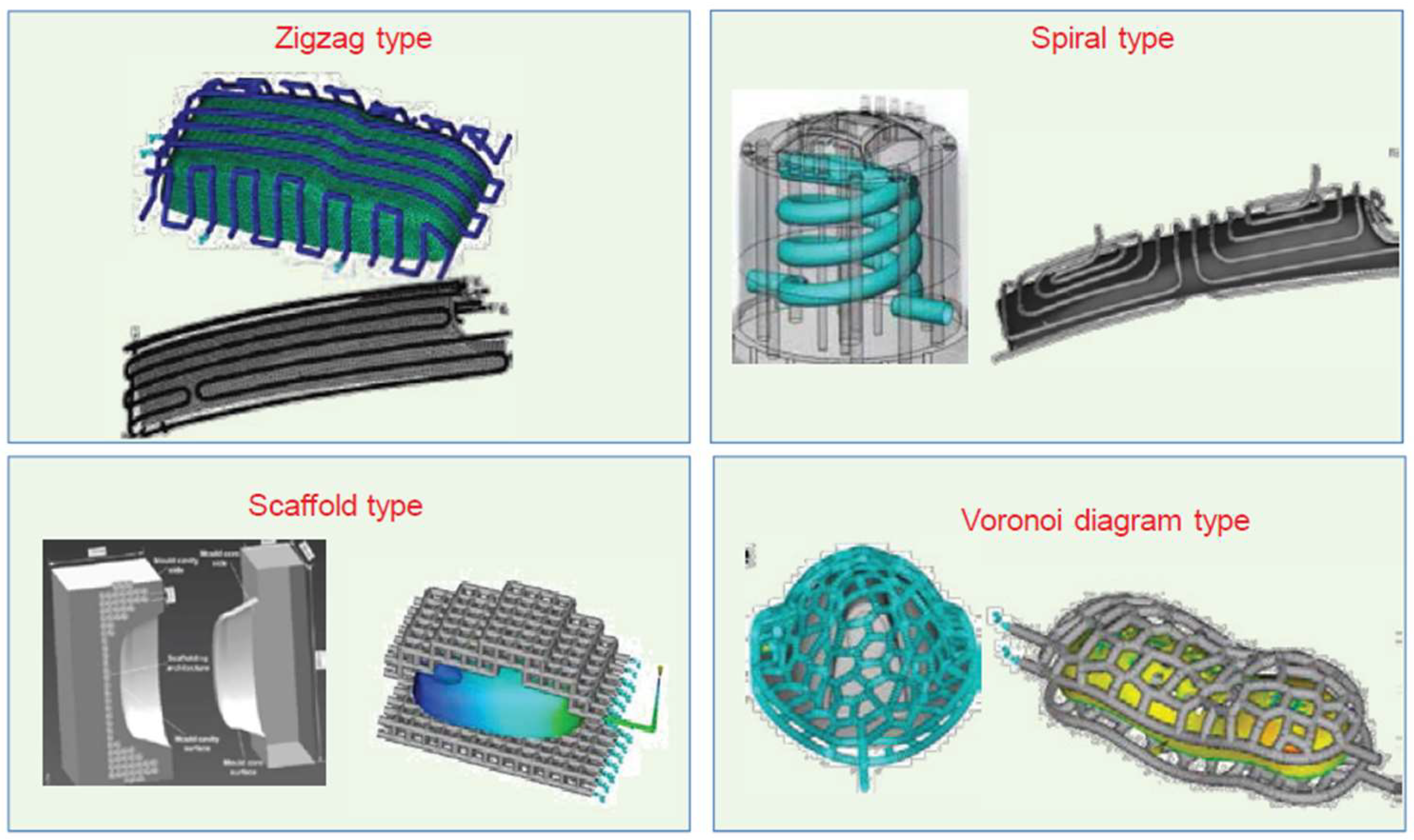
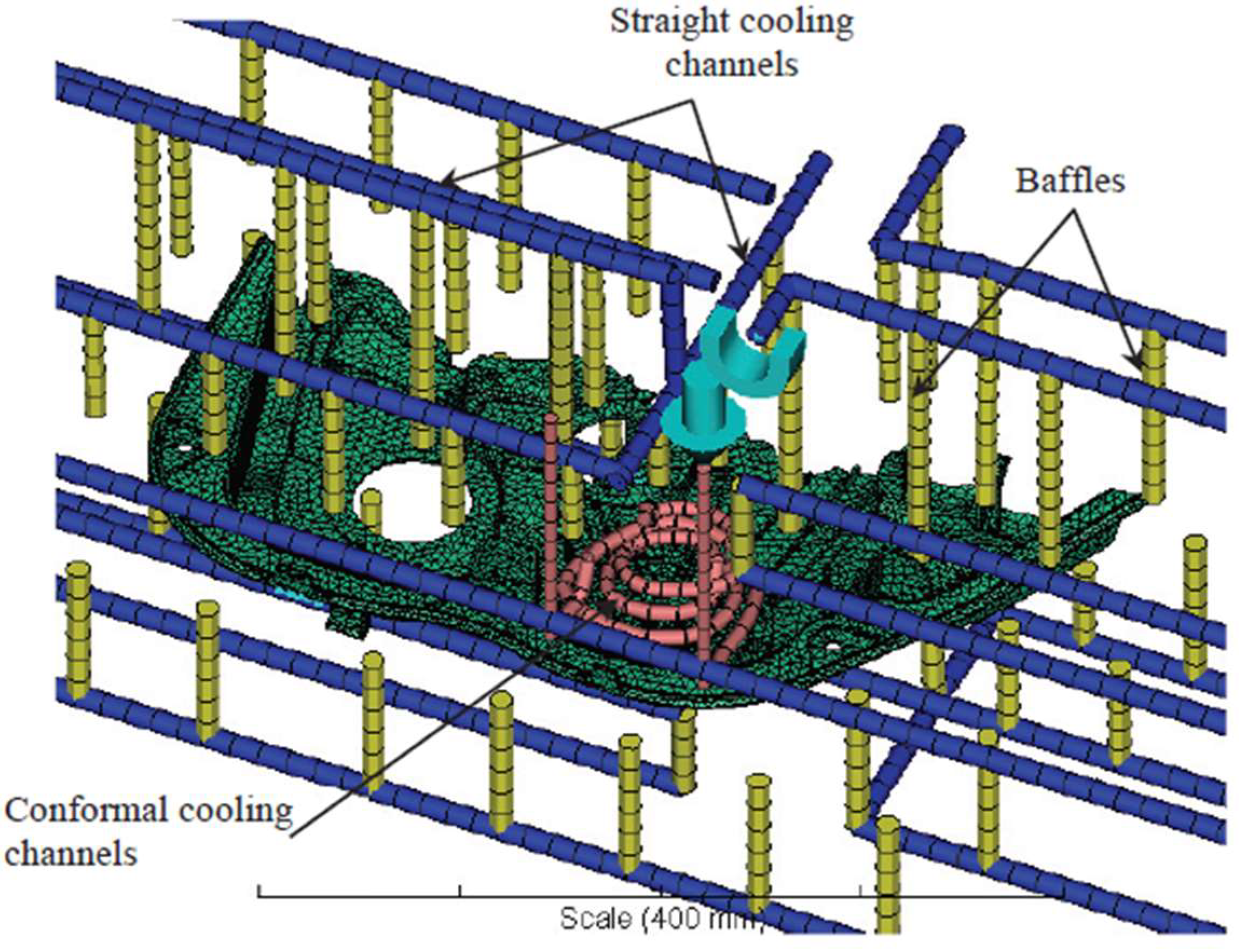
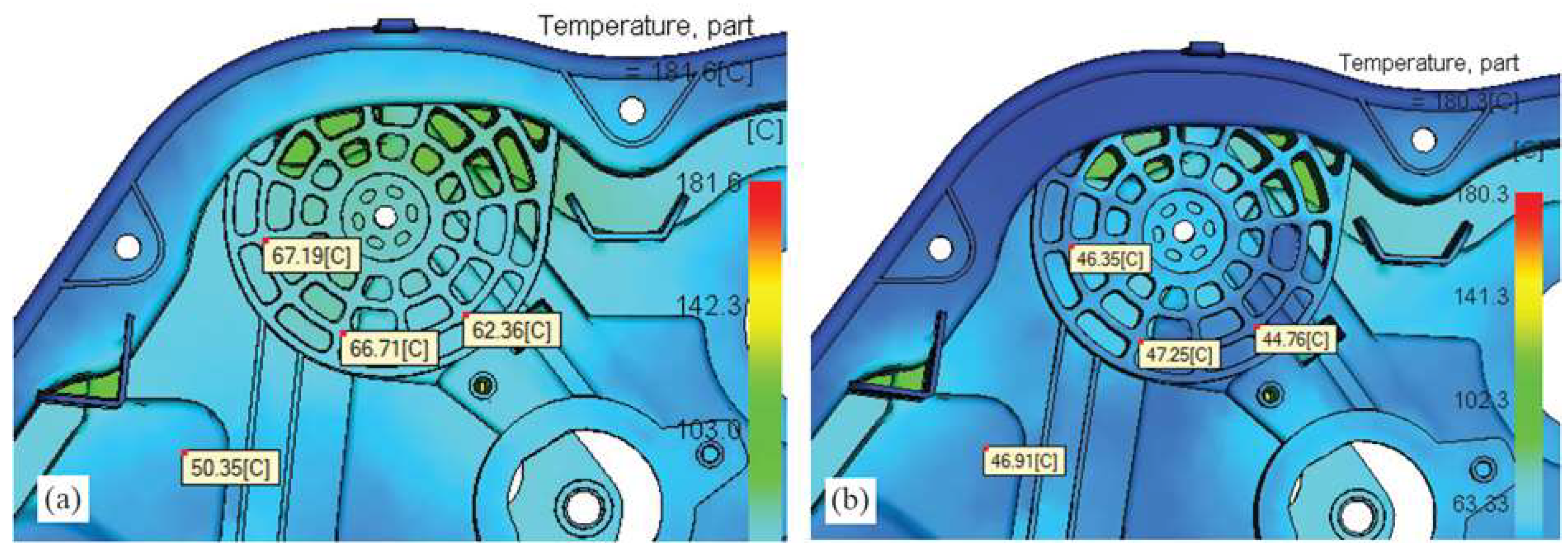
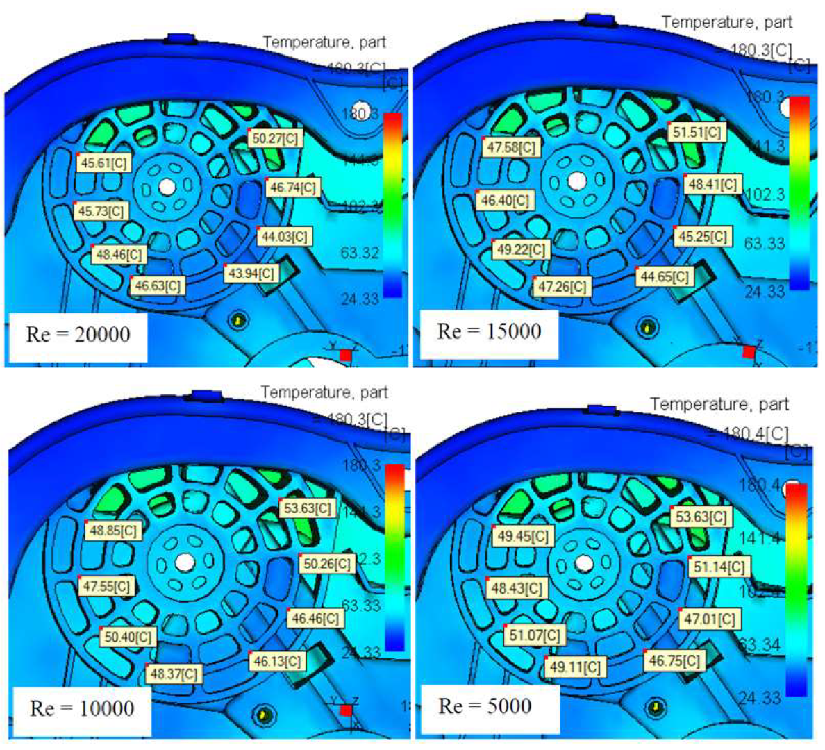

Disclaimer/Publisher’s Note: The statements, opinions and data contained in all publications are solely those of the individual author(s) and contributor(s) and not of MDPI and/or the editor(s). MDPI and/or the editor(s) disclaim responsibility for any injury to people or property resulting from any ideas, methods, instructions or products referred to in the content. |
© 2025 by the authors. Licensee MDPI, Basel, Switzerland. This article is an open access article distributed under the terms and conditions of the Creative Commons Attribution (CC BY) license (https://creativecommons.org/licenses/by/4.0/).