
Comprehensive Investigation of Efficiency Improvement in Voltage Source Inverter Using Hybrid Carrier-Based Modulation


Abstract
:1. Introduction
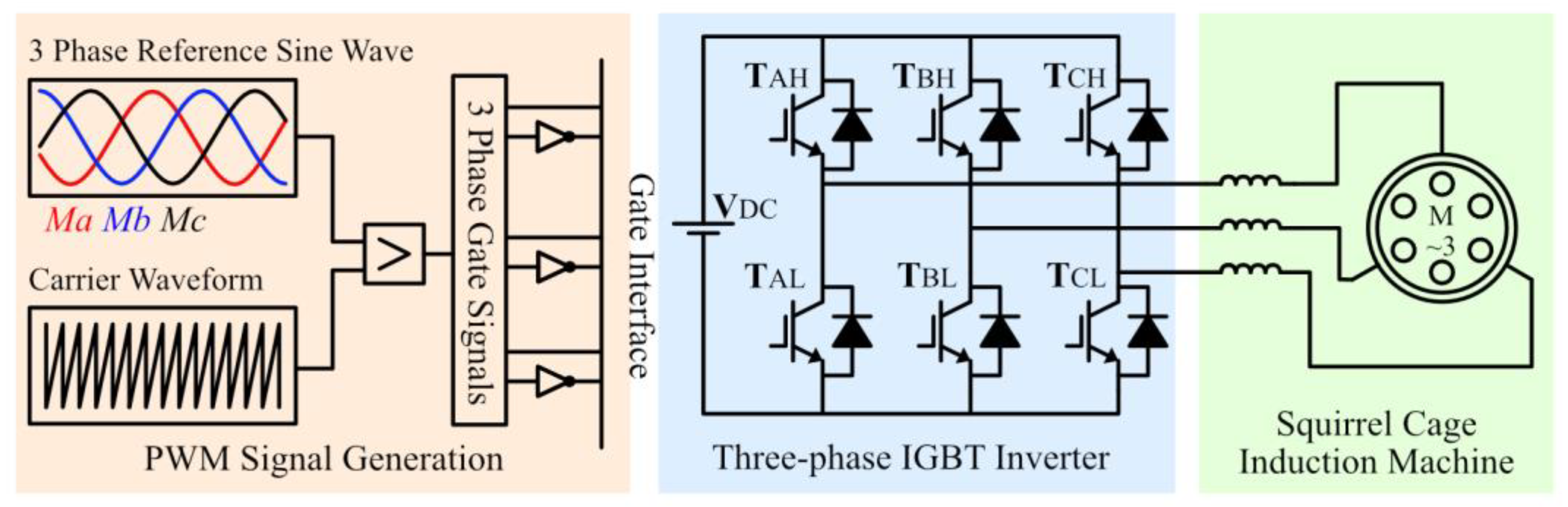
2. VSI Inverter Basics and Control Principles
2.1. SPWM Basics
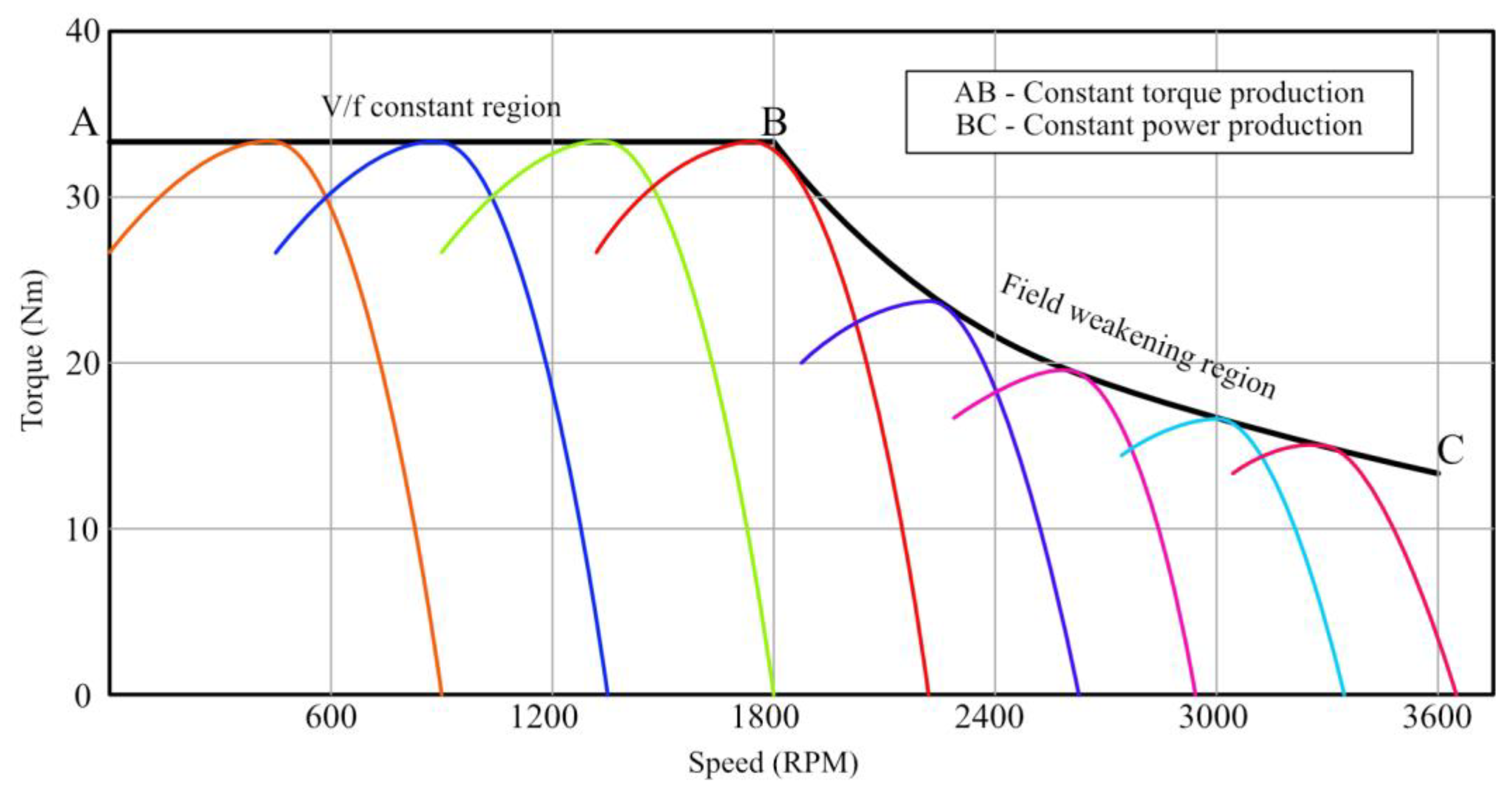
2.2. Voltage by Frequency Control
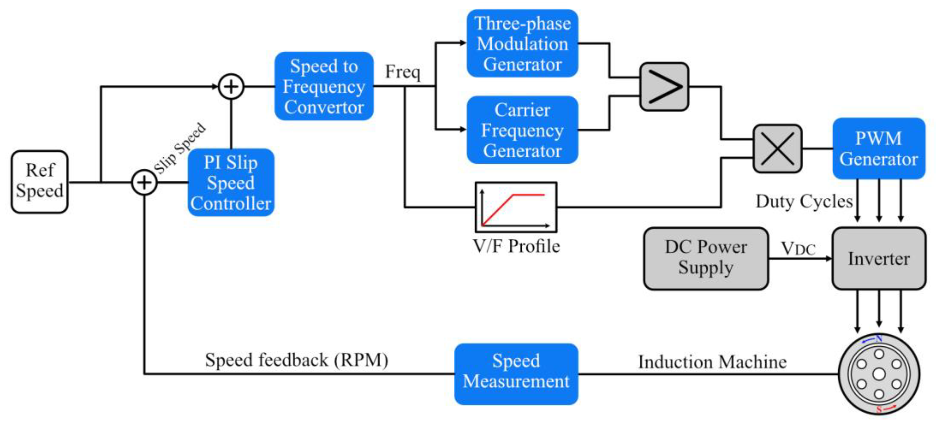
2.3. Closed-Loop Speed Control
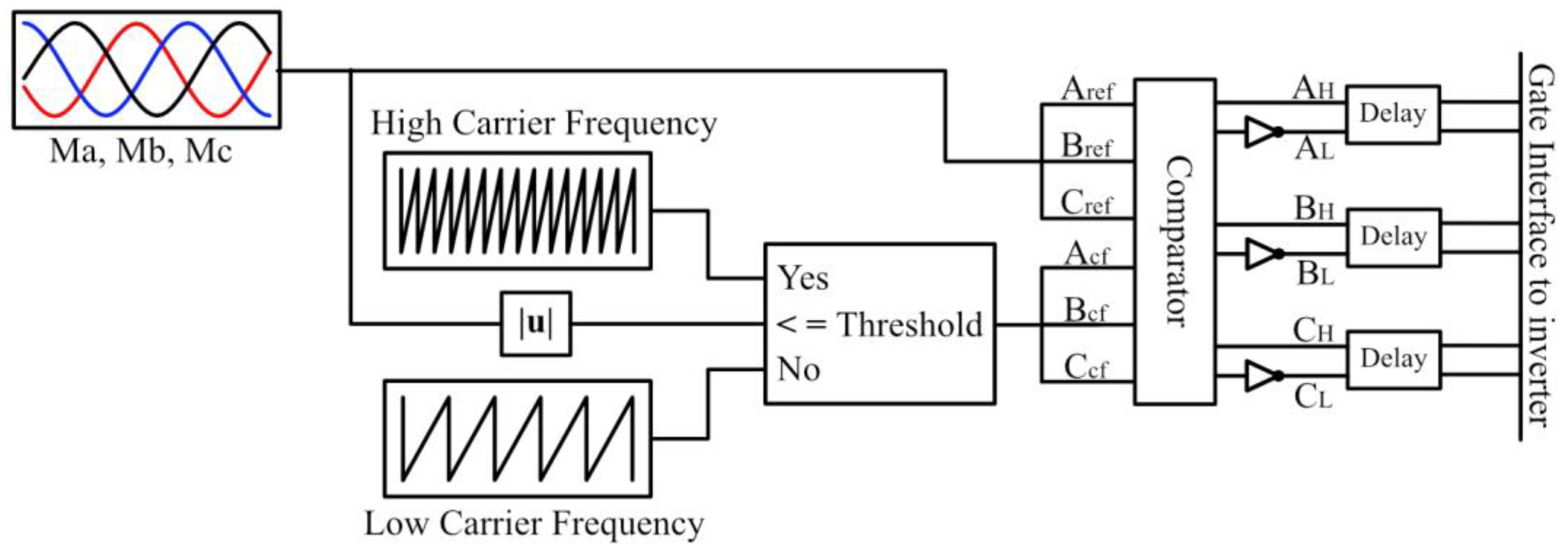
3. HCPWM Basics
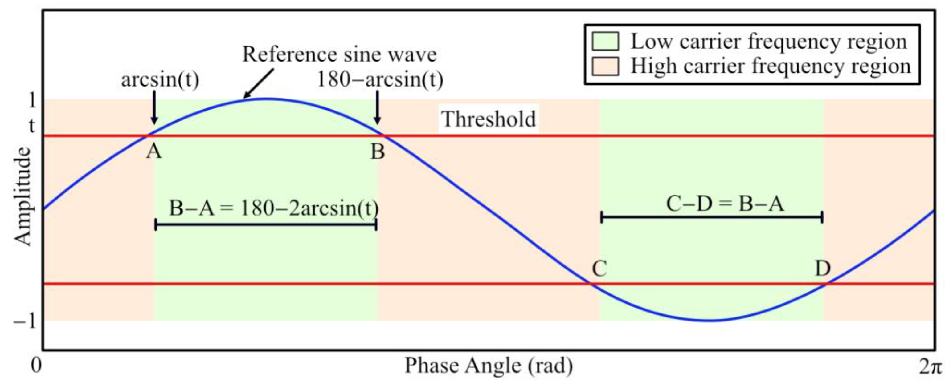
3.1. Design of HC
- HC = hybrid carrier signal;
- FCH = high-frequency saw-tooth wave;
- FCL = low-frequency saw-tooth wave;
- T = threshold value.
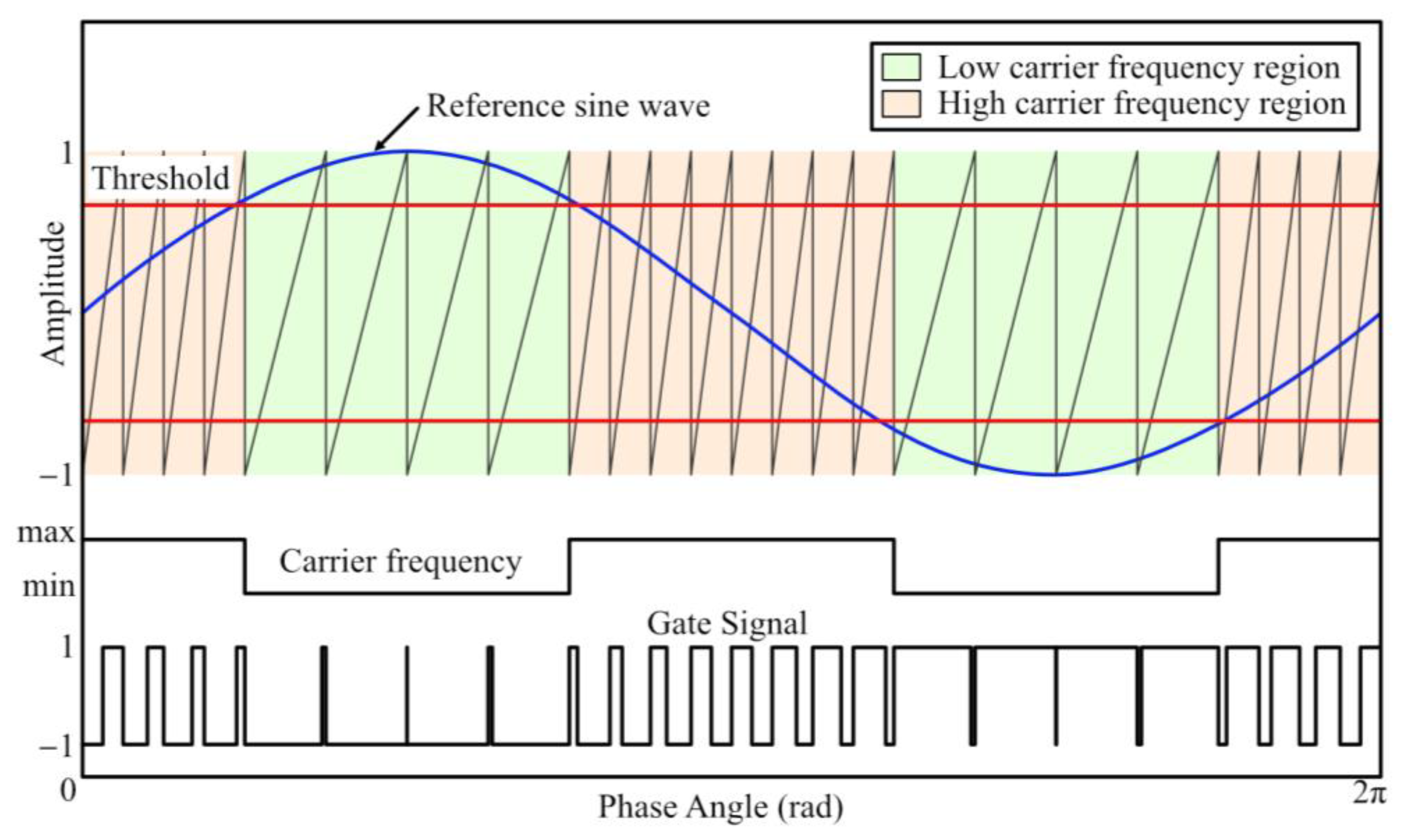
3.2. HCPWM Implementation
4. Inverter’s Switching Loss and Efficiency
4.1. Switching Loss
4.2. Power and Energy Efficiency
- = instantaneous phase voltages;
- = instantaneous phase currents;
- = power efficiency.
5. Results
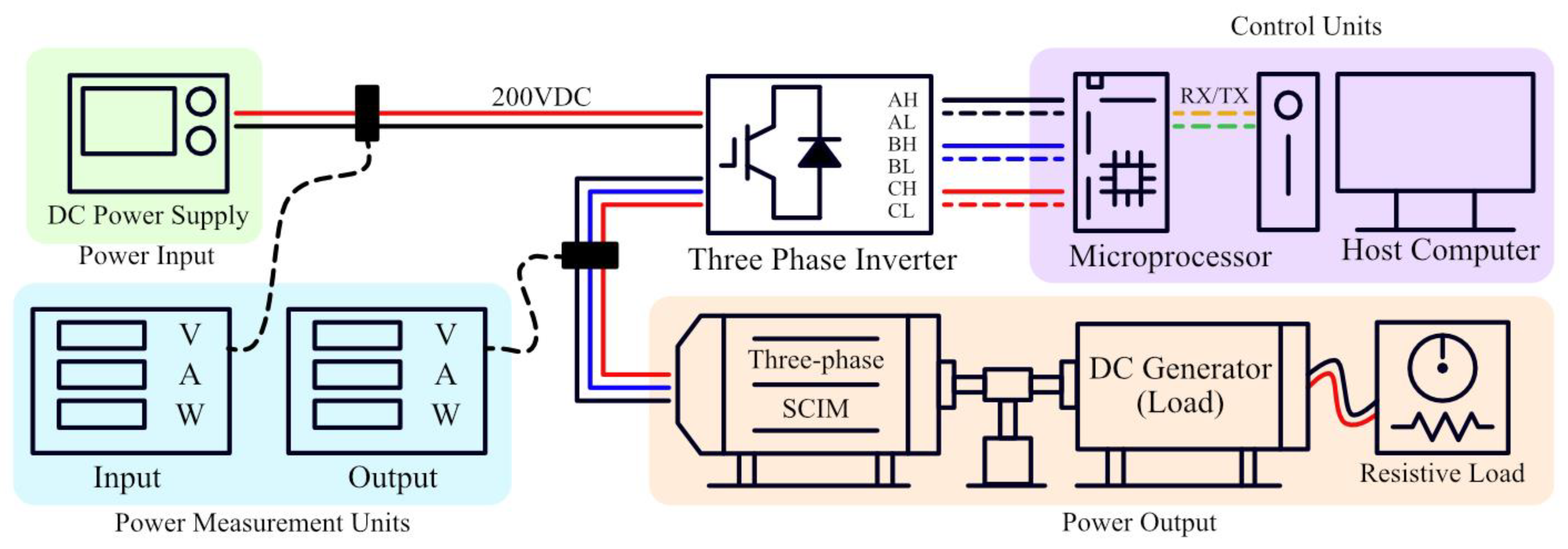
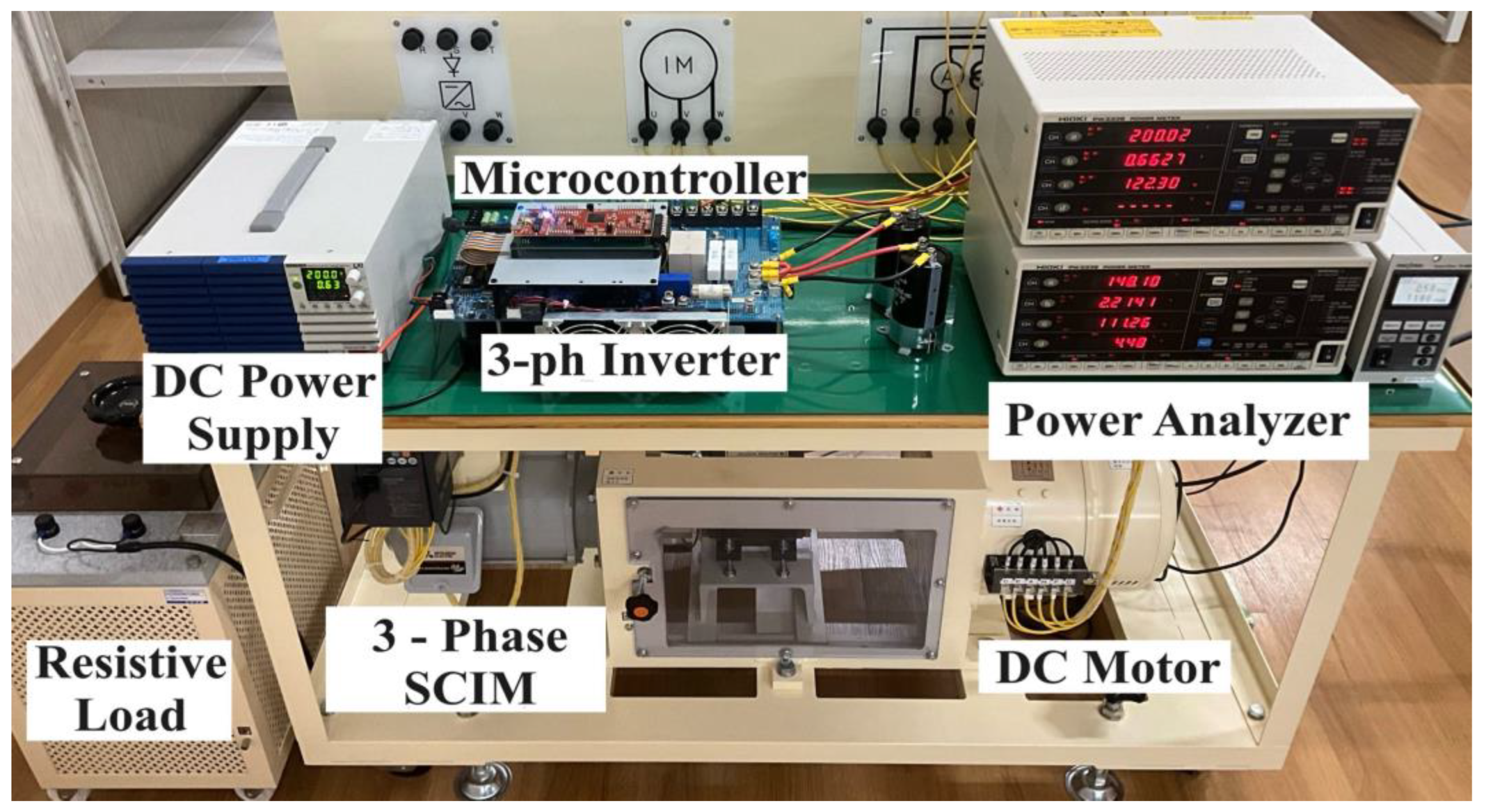
5.1. Experimental Configuration and Conditions
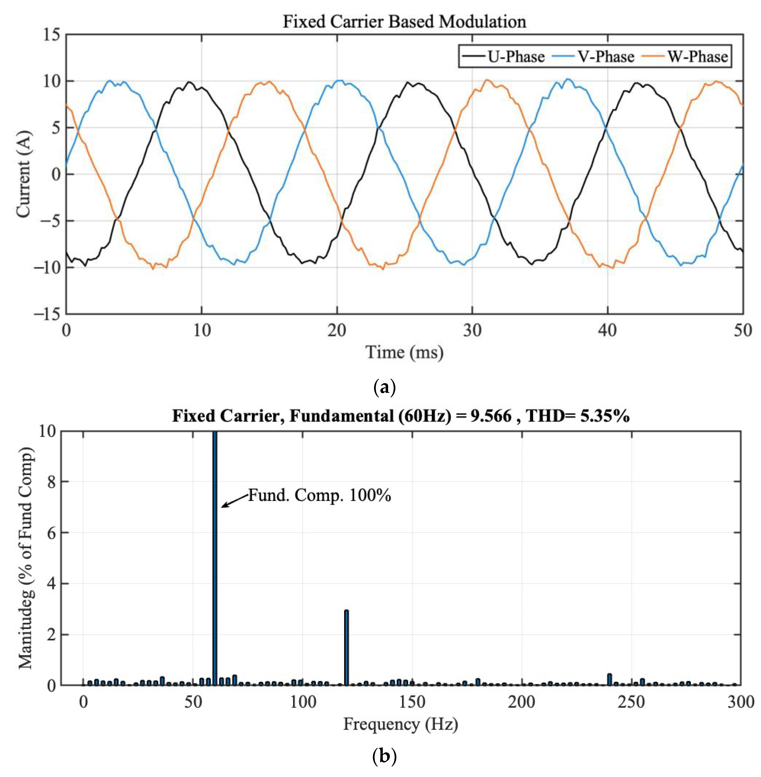
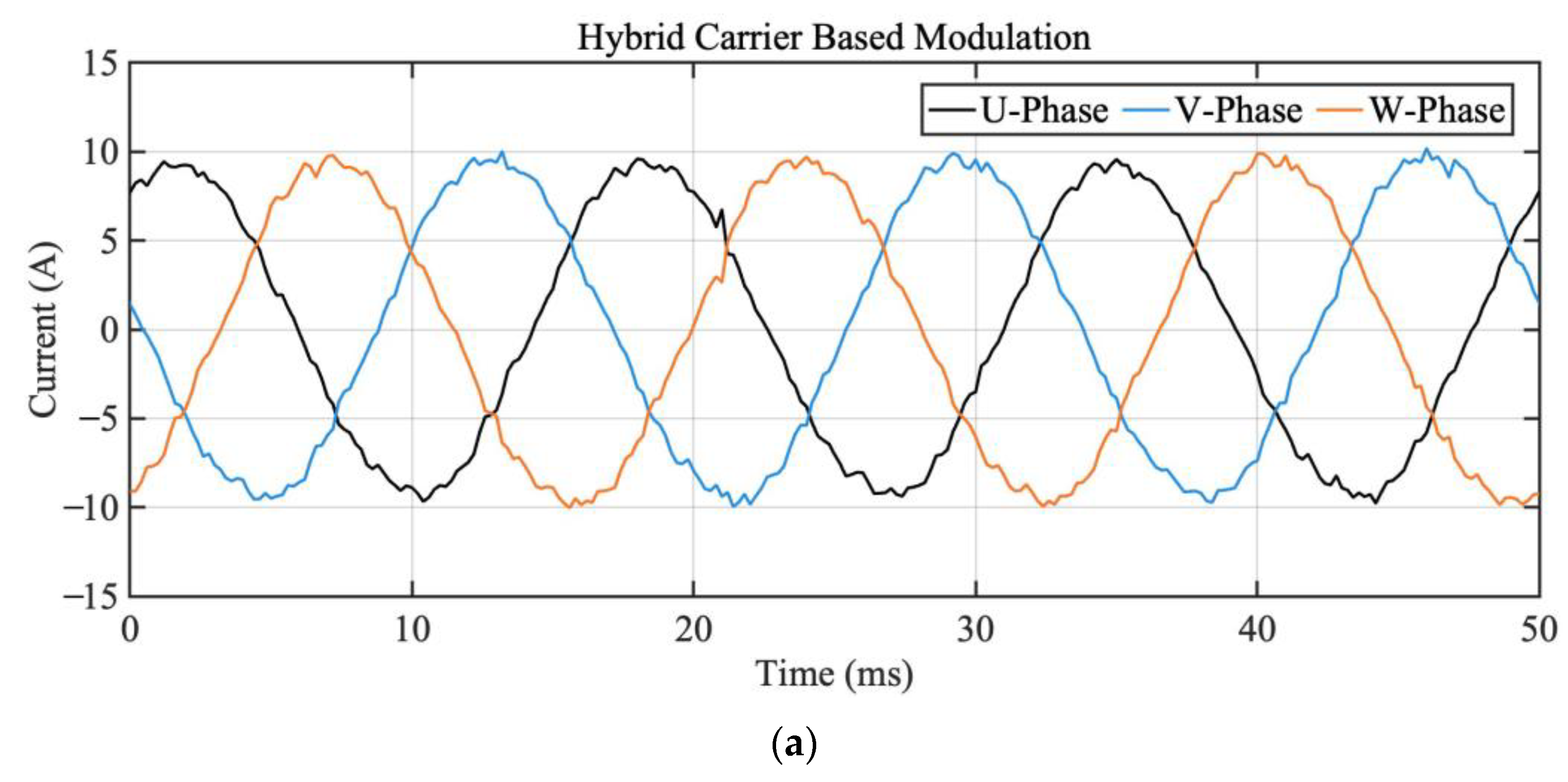
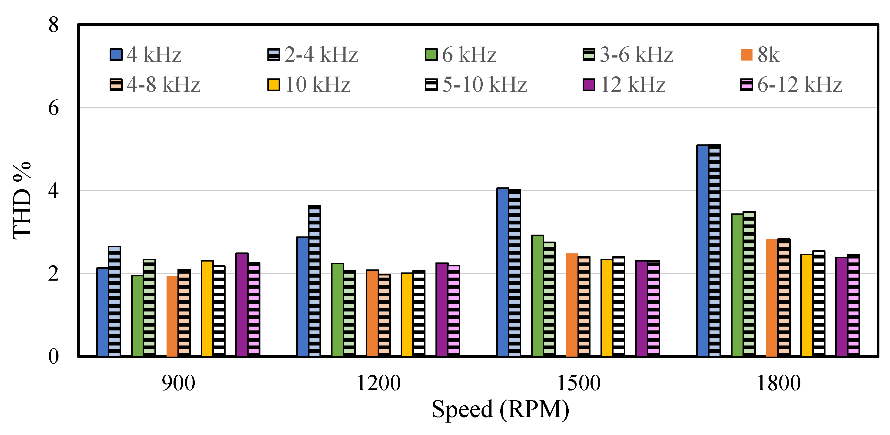
5.2. THD and Efficiency at Steady-State Operation
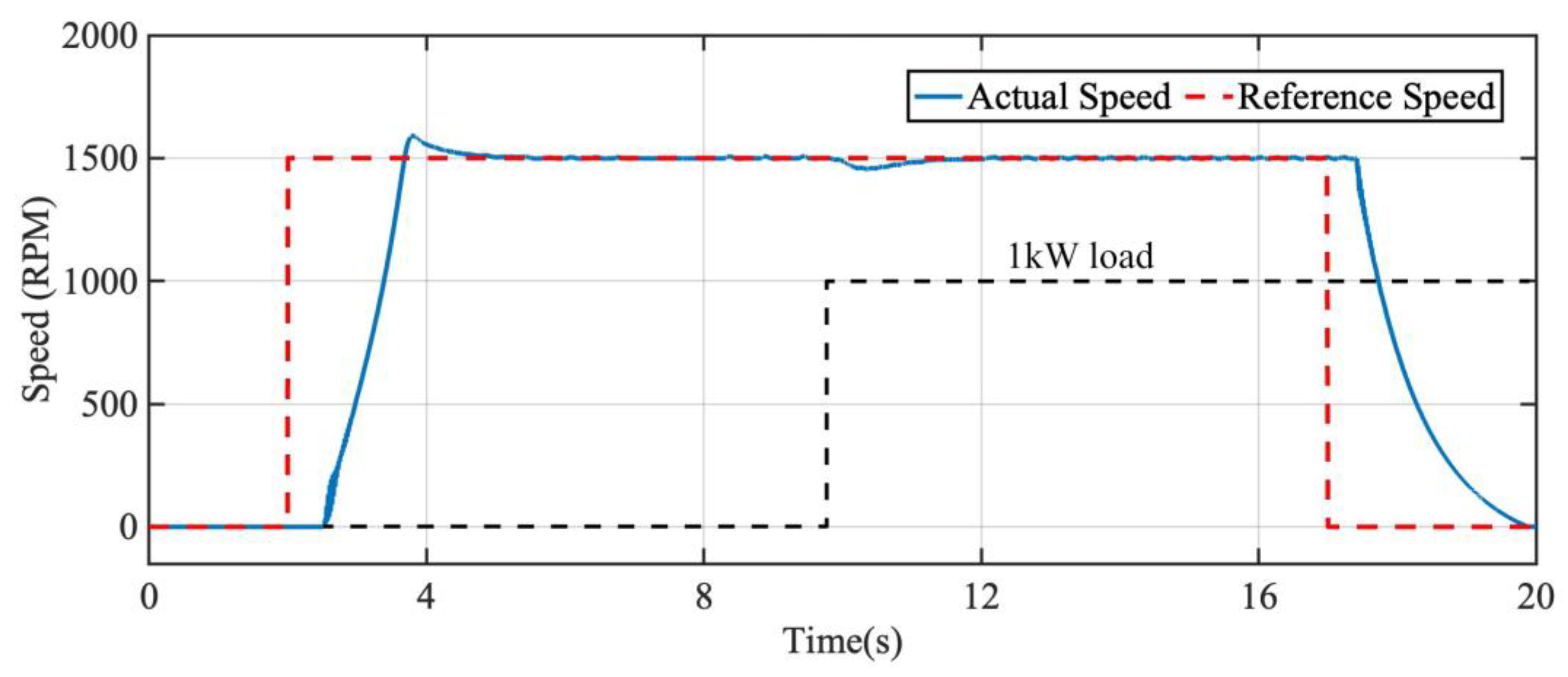
5.3. Efficiency Comparison in Dynamic Operation
6. Conclusions
Author Contributions
Funding
Data Availability Statement
Conflicts of Interest
Abbreviations
| VSD | Variable-Speed Drive |
| VSI | Voltage Source Inverter |
| PWM | Pulse-Width Modulation |
| HCPWM | Hybrid Carrier-based PWM |
| FCPWM | Fixed Carrier-based PWM |
| THD | Total harmonic distortion |
| SCIM | Squirrel-Cage Induction Machine |
| SPWM | Sine Pulse-Width Modulation |
References
- Sadigh, A.K.; Round, S.D. A Survey on Voltage Source Inverters for Adjustable Speed Drive Applications. IEEE Trans. Power Electron. 2021, 36, 1302–1315. [Google Scholar]
- Srivastava, S.; Chaudhari, M.A. Comparison of SVPWM and SPWM Schemes for NPC Multilevel Inverter. In Proceedings of the 2020 IEEE International Students’ Conference on Electrical, Electronics and Computer Science (SCEECS), Bhopal, India, 22–23 February 2020; pp. 1–6. [Google Scholar] [CrossRef]
- Tahir, S.; Wang, J.; Baloch, M.H.; Kaloi, G.S. Digital Control Techniques Based on Voltage Source Inverters in Renewable Energy Applications: A Review. Electronics 2018, 7, 18. [Google Scholar] [CrossRef]
- Pathak, P.K.; Yadav, A.K.; Tyagi, P. Design of Three Phase Grid Tied Solar Photovoltaic System Based on Three Phase VSI. In Proceedings of the 2018 8th IEEE India International Conference on Power Electronics (IICPE), Jaipur, India, 13–15 December 2018; pp. 1–6. [Google Scholar] [CrossRef]
- Ogudo, K.A.; Makhubele, J.W. Comparative Analysis on Modulation Techniques for A Single Phase Full-Bridge Inverter on Hysteresis Current Control PWM, Sinusoidal PWM and Modified Sinusoidal PWM. In Proceedings of the 2019 International Conference on Advances in Big Data, Computing and Data Communication Systems (icABCD), Winterton, South Africa, 5–6 August 2019; pp. 1–7. [Google Scholar] [CrossRef]
- Tan, B.; Gu, Z.; Shen, K.; Ding, X. Third Harmonic Injection SPWM Method Based on Alternating Carrier Polarity to Suppress the Common Mode Voltage. IEEE Access 2019, 7, 9805–9816. [Google Scholar] [CrossRef]
- Narasimha Rao, C.N.; DurgaSukumar, G. Analysis of Torque Ripple in Vector Control of BLDC Motor using SVPWM Technique. In Proceedings of the 2020 4th International Conference on Electronics, Communication and Aerospace Technology (ICECA), Coimbatore, India, 5–7 November 2020; pp. 519–523. [Google Scholar] [CrossRef]
- Zou, Y.; Zhang, L.; Xing, Y.; Zhuge, H.; Mo, W.; Wu, Y.; Shen, X. Enhanced Carrier-Based Discontinuous PWM for Three-Level Inverters With Unbalanced Neutral-Point Voltage. IEEE J. Emerging Sel. Topics Power Electron. 2024, 12, 2176–2187. [Google Scholar] [CrossRef]
- Ghorbani, J.; Mokhtari, H. Impact of Harmonics on Power Quality and Losses in Power Distribution Systems. Int. J. Electr. Comput. Eng. 2015, 5, 166. [Google Scholar] [CrossRef]
- IEC 61000-3-2; Electromagnetic Compatibility (EMC)—Part 3-2: Limits—Limits for Harmonic Current Emissions (Equipment Input Current ≤ 16 A per Phase). IEC: Geneva, Switzerland, 2018.
- IEEE Std 519-2014; IEEE Recommended Practice and Requirements for Harmonic Control in Electric Power Systems. IEEE: New York, NY, USA, 2014.
- Lee, H.-J.; Yoo, A.; Hong, C.; Lee, J. A Carrier-Based Adjustable Discontinuous PWM for Three-Phase Voltage Source Inverter. In Proceedings of the 2015 IEEE Energy Conversion Congress and Exposition (ECCE), Montreal, QC, Canada, 20–24 September 2015; pp. 2870–2875. [Google Scholar] [CrossRef]
- Liu, Z.; Wang, P.; Sun, W.; Shen, Z.; Jiang, D. Sawtooth Carrier-Based PWM Methods With Common-Mode Voltage Reduction for Symmetrical Multiphase Two-Level Inverters With Odd Phase Number. IEEE Trans. Power Electron. 2021, 36, 1171–1183. [Google Scholar] [CrossRef]
- Lee, J.; Kim, M.-W.; Park, J.-W. Carrier Selection Strategy of Generalized Discontinuous PWM Method for Current Reduction in DC-Link Capacitors of VSI. IEEE Trans. Power Electron. 2022, 37, 10428–10442. [Google Scholar] [CrossRef]
- Shukla, K.; Malyala, V.; Maheshwari, R. A Novel Carrier-Based Hybrid PWM Technique for Minimization of Line Current Ripple in Two Parallel Interleaved Two-Level VSIs. IEEE Trans. Ind. Electron. 2018, 65, 1908–1918. [Google Scholar] [CrossRef]
- Ahmed, A.; Biswas, S.P.; Anower, M.S.; Islam, M.R.; Mondal, S.; Muyeen, S.M. A Hybrid PWM Technique to Improve the Performance of Voltage Source Inverters. IEEE Access 2023, 11, 4717–4729. [Google Scholar] [CrossRef]
- Gao, Z.; Ge, Q.; Li, Y.; Zhao, L.; Zhang, B.; Wang, K. Hybrid Improved Carrier-Based PWM Strategy for Three-Level Neutral-Point-Clamped Inverter With Wide Frequency Range. IEEE Trans. Power Electron. 2021, 36, 8517–8538. [Google Scholar] [CrossRef]
- Than, Y.; Kucuk, F. Hybrid Carrier Frequency Based Modulation Strategy to Improve Efficiency of Voltage Source Inverter. In Proceedings of the 2024 Third International Conference on Power, Control and Computing Technologies (ICPC2T), Raipur, India, 18–20 January 2024; pp. 703–708. [Google Scholar]
- Sharma, A.; Kumar, R. Design and implementation of a two-phase three-level inverter for medium voltage applications. IEEE Trans. Power Electron. 2023, 38, 2456–2464. [Google Scholar]
- Liyanage, A.; Nagrial, M.; Hellany, A.; Rizk, J. Speed Control of Induction Motors Using V/f Control Method. In Proceedings of the 2022 International Conference on Electrical and Computing Technologies and Applications (ICECTA), Ras Al Khaimah, United Arab Emirates, 23–25 November 2022. [Google Scholar]
- Than, Y.; Kucuk, F. Adaptable Hybrid Carrier Frequency Control Method for Variable Speed Voltage Source Inverter. In Proceedings of the 2024 8th International Conference on Power Energy Systems and Applications (ICoPESA), Hong Kong, 24–26 June 2024; pp. 199–204. [Google Scholar] [CrossRef]
- Kulkarni, C.; Kodeeswara Kumaran, G.; Sridhar, S. Implementation of Closed Loop V/Hz Control of Induction Motor Drive Using Tms320F28035 and Altair sT Embed. In Proceedings of the 2021 International Conference on Circuits, Controls and Communications (CCUBE), Bangalore, India, 23–24 December 2021; pp. 1–4. [Google Scholar] [CrossRef]
- Hunasikatti, K.B.; Naik, R.L.; Hiremath, B.V. Implementation of FPGA-Based Closed Loop V/f Speed Control of Induction Motor Employed for Industrial Applications. In Proceedings of the 2018 Second International Conference on Advances in Electronics, Computers and Communications (ICAECC), Bangalore, India, 9–10 February 2018; pp. 1–6. [Google Scholar] [CrossRef]
- Ito, J.; Toyosaki, J.; Ohsawa, H. High Performance V/f Control Method for PM Motor. IEEJ Trans. Ind. Appl. 2002, 122, 253–259. [Google Scholar] [CrossRef]
- Tochigi, D.; Takashima, K.; Isobe, T.; Tadano, H.; Tomoyuki, M. Experimental Verification of a Model of Switching Transients Considering Device Parasitic Capacitance for the Loss Estimation of Soft-Switching Power Converters. In Proceedings of the 2019 IEEE 4th International Future Energy Electronics Conference (IFEEC), Singapore, 25–28 November 2019; pp. 1–7. [Google Scholar] [CrossRef]
- Gangwar, A.; Chanekar, A.; Anand, S.; Verma, A. De-Skewing Algorithm for Accurate Switching Loss Calculation in GaN HEMT. In Proceedings of the 2024 IEEE Transportation Electrification Conference and Expo (ITEC), Chicago, IL, USA, 19–21 June 2024; pp. 1–6. [Google Scholar] [CrossRef]
- Aydin, M.; Beşer, E. Power Loss and Thermal Temperature Calculation of IGBT Module by Mathematical Equations. In Proceedings of the 2023 International Conference on Power Energy Systems and Applications (ICoPESA), Nanjing, China, 24–26 February 2023; pp. 862–867. [Google Scholar] [CrossRef]
- Islam, M.M.; Rahman, M.A.; Islam, M.R. Power Loss and Thermal Impedance Modeling of Multilevel Power Converter with Discontinuous Modulation. IEEE Trans. Energy Convers. 2021, 36, 36–47. [Google Scholar] [CrossRef]
- IEEE P2747/D7.0; IEEE Approved Draft Guide for Energy Efficiency Technology Evaluation of Electric Power Fittings. IEEE: Piscataway, NJ, USA, 2020.
- Murdock, J.N.; Rappaport, T.S. Consumption Factor and Power-Efficiency Factor: A Theory for Evaluating the Energy Efficiency of Cascaded Communication Systems. IEEE J. Sel. Areas Commun. 2014, 32, 221–236. [Google Scholar] [CrossRef]


| Parameter | Carrier Type/Frequency | ||
|---|---|---|---|
| Fixed Carrier 6 kHz | Hybrid Carrier 3–6 kHz | ||
| 900 RPM | Input energy (Wh) | 4.127 | 3.896 |
| Output energy (Wh) | 3.932 | 3.721 | |
| Efficiency (%) | 95.28 | 95.51 | |
| 1200 RPM | Input energy (Wh) | 3.915 | 3.848 |
| Output energy (Wh) | 3.765 | 3.712 | |
| Efficiency (%) | 96.17 | 96.47 | |
| 1500 RPM | Input energy (Wh) | 3.788 | 3.761 |
| Output energy (Wh) | 3.656 | 3.645 | |
| Efficiency (%) | 96.52 | 96.92 | |
| 1800 RPM | Input energy (Wh) | 3.646 | 3.627 |
| Output energy (Wh) | 3.529 | 3.523 | |
| Efficiency (%) | 96.79 | 97.13 | |
Disclaimer/Publisher’s Note: The statements, opinions and data contained in all publications are solely those of the individual author(s) and contributor(s) and not of MDPI and/or the editor(s). MDPI and/or the editor(s) disclaim responsibility for any injury to people or property resulting from any ideas, methods, instructions or products referred to in the content. |
© 2025 by the authors. Licensee MDPI, Basel, Switzerland. This article is an open access article distributed under the terms and conditions of the Creative Commons Attribution (CC BY) license (https://creativecommons.org/licenses/by/4.0/).
Share and Cite
Than, Y.; Kucuk, F. Comprehensive Investigation of Efficiency Improvement in Voltage Source Inverter Using Hybrid Carrier-Based Modulation. Energies 2025, 18, 2053. https://doi.org/10.3390/en18082053
Than Y, Kucuk F. Comprehensive Investigation of Efficiency Improvement in Voltage Source Inverter Using Hybrid Carrier-Based Modulation. Energies. 2025; 18(8):2053. https://doi.org/10.3390/en18082053
Chicago/Turabian StyleThan, Yu, and Fuat Kucuk. 2025. "Comprehensive Investigation of Efficiency Improvement in Voltage Source Inverter Using Hybrid Carrier-Based Modulation" Energies 18, no. 8: 2053. https://doi.org/10.3390/en18082053
APA StyleThan, Y., & Kucuk, F. (2025). Comprehensive Investigation of Efficiency Improvement in Voltage Source Inverter Using Hybrid Carrier-Based Modulation. Energies, 18(8), 2053. https://doi.org/10.3390/en18082053