Article

An Investigation into the Saliency Ratio of Fractional-Slot Concentrated-Winding Generators for Offshore Wind Power

by
Isaac Rudden
1,
Guang-Jin Li
1,*,
Zi-Qiang Zhu
1,
Alexander Duke
2 and
Richard Clark
2
1
Electrical Machines & Drives Group, Department of Electronic and Electrical Engineering, University of Sheffield, Sheffield S10 2TN, UK
2
Siemens Gamesa Renewable Energy Ltd., North Campus, Broad Lane, Sheffield S3 7HQ, UK
*
Author to whom correspondence should be addressed.
Energies 2025, 18(8), 2057; https://doi.org/10.3390/en18082057
Submission received: 14 March 2025 / Revised: 9 April 2025 / Accepted: 15 April 2025 / Published: 17 April 2025

Abstract

:
This paper investigates the nature of the low saliency ratio of large permanent magnet generators with fractional-slot concentrated windings (FSCWs). A saliency ratio of at least 1.2 is typically required to enable sensorless control of large generators—a value naturally achieved in integer slot winding topologies but absent in FSCW surface-mounted permanent magnet machines reported in the literature. The low saliency ratio in FSCW designs is attributed to larger teeth, which reduce magnetic saturation and increase d-axis inductance. This work explores methods to enhance the saliency ratio of FSCW machines for offshore wind turbines, facilitating sensorless rotor position estimation. The proposed approaches are categorized into two groups: (1) those that preserve the conventional machine geometry with minimal modification to the magnetic circuit and (2) those involving magnetic circuit alterations. The results show that significant improvement in saliency ratio is only achievable through magnetic circuit modifications, such as rotor shoes, albeit with some performance trade-offs. A multi-objective genetic algorithm is employed to design two optimized 3 MW FSCW machine topologies, achieving saliency ratios of 1.15 and 1.2 with minimal performance loss. Compared to a 3 MW FSCW baseline, the optimized designs show stator power reductions of 3.40% and 6.16% for saliency ratios of 1.15 and 1.2, respectively.

1. Introduction

Sensorless control is an increasingly popular method for rotor position estimation that eliminates the need for shaft-mounted sensors [1,2]. These sensors add to system cost and can be a point of failure for a machine, this being particularly problematic for offshore wind turbines where failure can lead to substantial loss of income. The advantages of sensorless control have led major wind power generator suppliers to utilize this control strategy in their offshore wind turbine generators, which are presently integer-slot winding (ISW) surface-mounted permanent magnet (SPM) machines. One of the most popular sensorless control methods, high-frequency injection, estimates the rotor position based on the difference between the d- and q-axis inductances, thereby requiring machine saliency. Machine saliency can be expressed using s a l i e n c y   r a t i o = L q / L d , where Ld and Lq are the d- and q-axis inductances, respectively. It is worth noting that selecting Lq/Ld as a saliency ratio is primarily because the investigated machines, featuring different winding structures, slot–pole number combinations, and magnetic circuit configurations, generally exhibit a larger Lq than Ld. As a result, using Lq/Ld yields a saliency ratio greater than 1, making the analysis more straightforward. A large saliency ratio is easily achieved with interior permanent magnet (IPM) rotors, as the anisotropic nature of the rotor structure inherent to the design yields magnetic saliency. Unfortunately, SPM rotors have homogeneous rotor structures, which do not produce a large difference in d- and q-axis inductances. For SPM machines, spatial saliency only comes from leakage flux saturation [3] or main flux saturation in the stator teeth [4,5].
For FSCWs to be an attractive choice for offshore wind power, they too must have the capacity to be controlled without sensors. However, FSCWs tend to exhibit much lower saliency ratios than their ISW counterparts. The larger ratio of stator pole pitch to rotor pole pitch in an FSCW machine leads to stator teeth that are much larger than those of an equivalent ISW. These larger teeth act as spatial low-pass filters that filter the magnetic permeance differences along orthogonal d- and q-axes and essentially smooth out rotor saliency effects [6,7]. This suggests that FSCWs are not the ideal choice for use with an IPM rotor as the low magnetic saliency reduces the reluctance torque capability of such machines [6]. In the case of SPM machines, which already have very low magnetic saliency owing to the isotropic rotor structure, this can effectively eliminate any capability for sensorless control with FSCWs. Methods have been proposed to assist with low-speed sensorless position estimation of FSCW SPM machines that use high-frequency voltage injection [8,9]. However, these methods still rely on some presence of magnetic saliency within the machine structure. Thus, investigating the saliency ratio of SPM machines with FSCWs and methods to improve it through machine design are still necessary.
Work has been carried out on improving the saliency ratio of SPM machines largely through the use of stator teeth and rotor pole shoes (or inset PMs). The contribution of q-axis leakage flux or ‘zigzag flux’ to q-axis inductance is identified in [3], and it is shown that the saliency ratio of a machine can be adjusted through induced saturation of PM flux within the stator tooth tips. In [10], this is then used to improve the saliency ratio of an SPM for sensorless control at zero and low speed. Another common method is the use of rotor pole shoes between the PMs that serve to increase q-axis inductance and thus improve the saliency ratio of SPM machines [11,12,13]. Unfortunately, while the inclusion of pole shoes serves to improve the saliency ratio, it has a detrimental impact on machine torque and efficiency [14].
This paper investigates the saliency ratio of large-scale FSCW generators, specifically 3 MW machines for offshore wind turbines. High-frequency injection-based sensorless control, commonly used in offshore wind power generators, typically requires a minimum saliency ratio of 1.2. To identify machines that can meet this requirement, this paper starts with comparing the saliency of a conventional 3 MW ISW machine (480s/160p) with an alternative FSCW machine (192s/160p) in Section 2. After identifying why there is a loss in the saliency ratio in the FSCW machine, a thorough investigation into methods to improve the saliency ratio is undertaken. These are split into two categories: those that maintain conventional geometry (Section 3) and those that alter the structure of the magnetic circuit (Section 4). It is found that it is very difficult to improve the saliency ratio of an FSCW SPM machine without magnetic circuit alteration, and this comes at a significant reduction in the electromagnetic performance of the machine. After selecting the best method for saliency improvement, in Section 5, global optimization is carried out to obtain two 3 MW machine designs that achieve saliency ratios of 1.15 and 1.2. It is found that these designs reduce the torque capability of the 3 MW machine by 1.8% and 5.4%, respectively. This, coupled with an increase in rotor eddy current losses, leads to a reduction in stator power of 3.46% and 6.26% for the machines with saliency ratios of 1.15 and 1.2, respectively.

2. Investigation into Saliency Ratios of 3 MW Machines

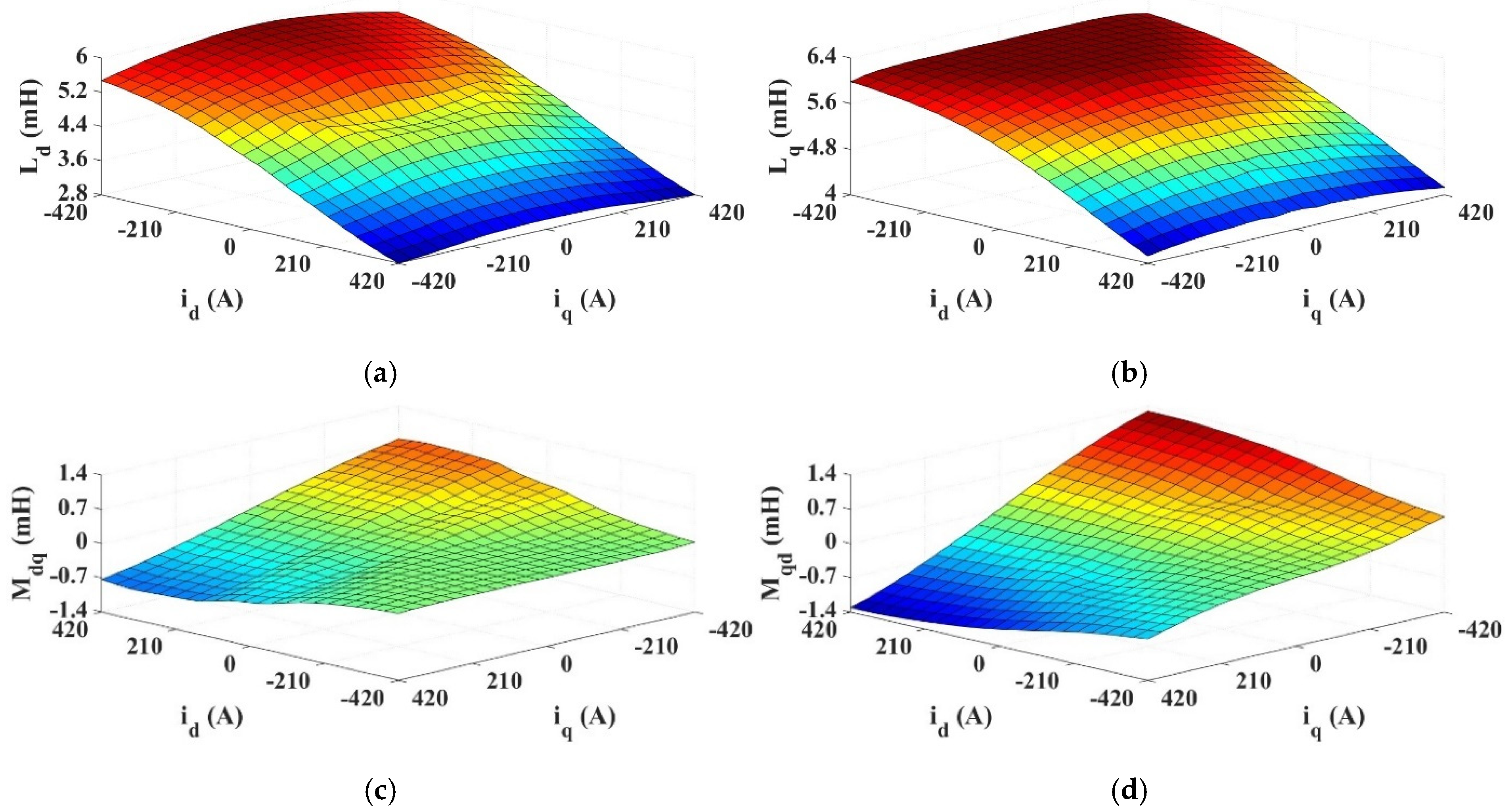
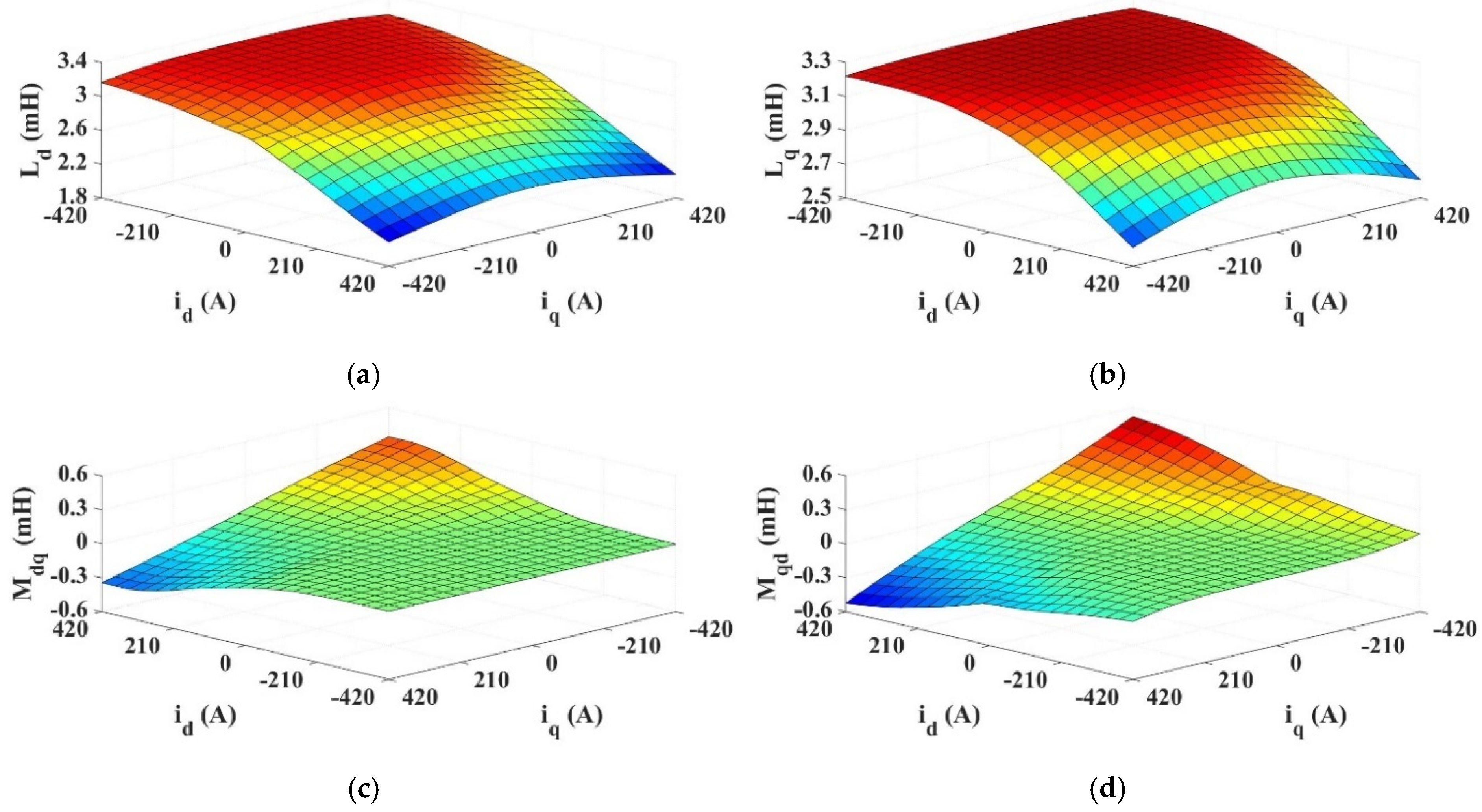
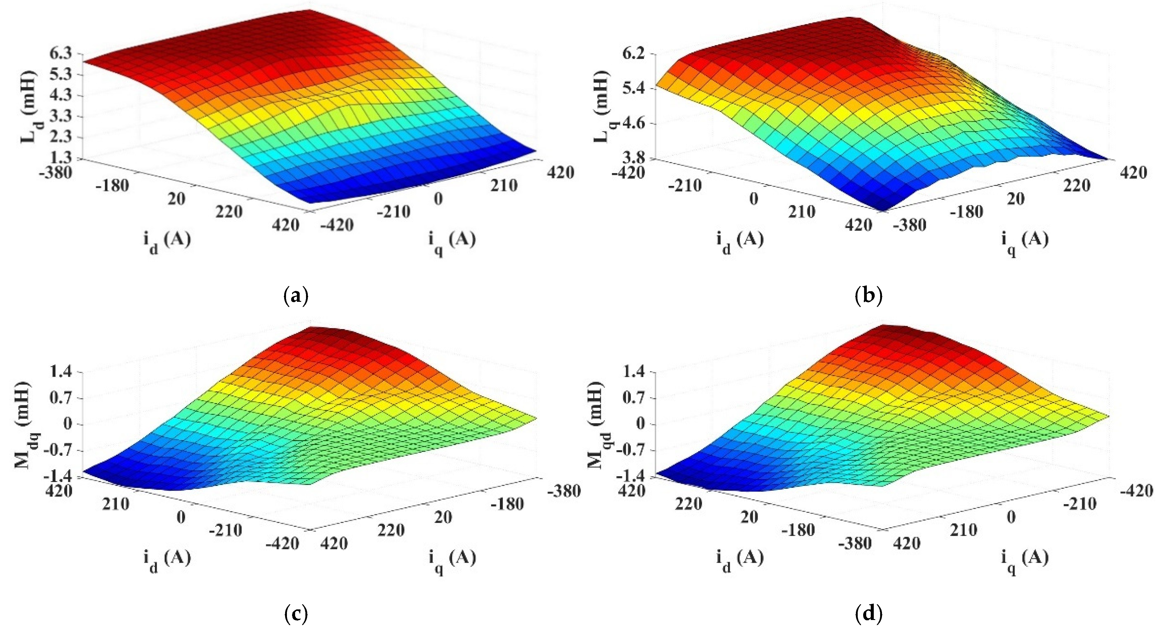
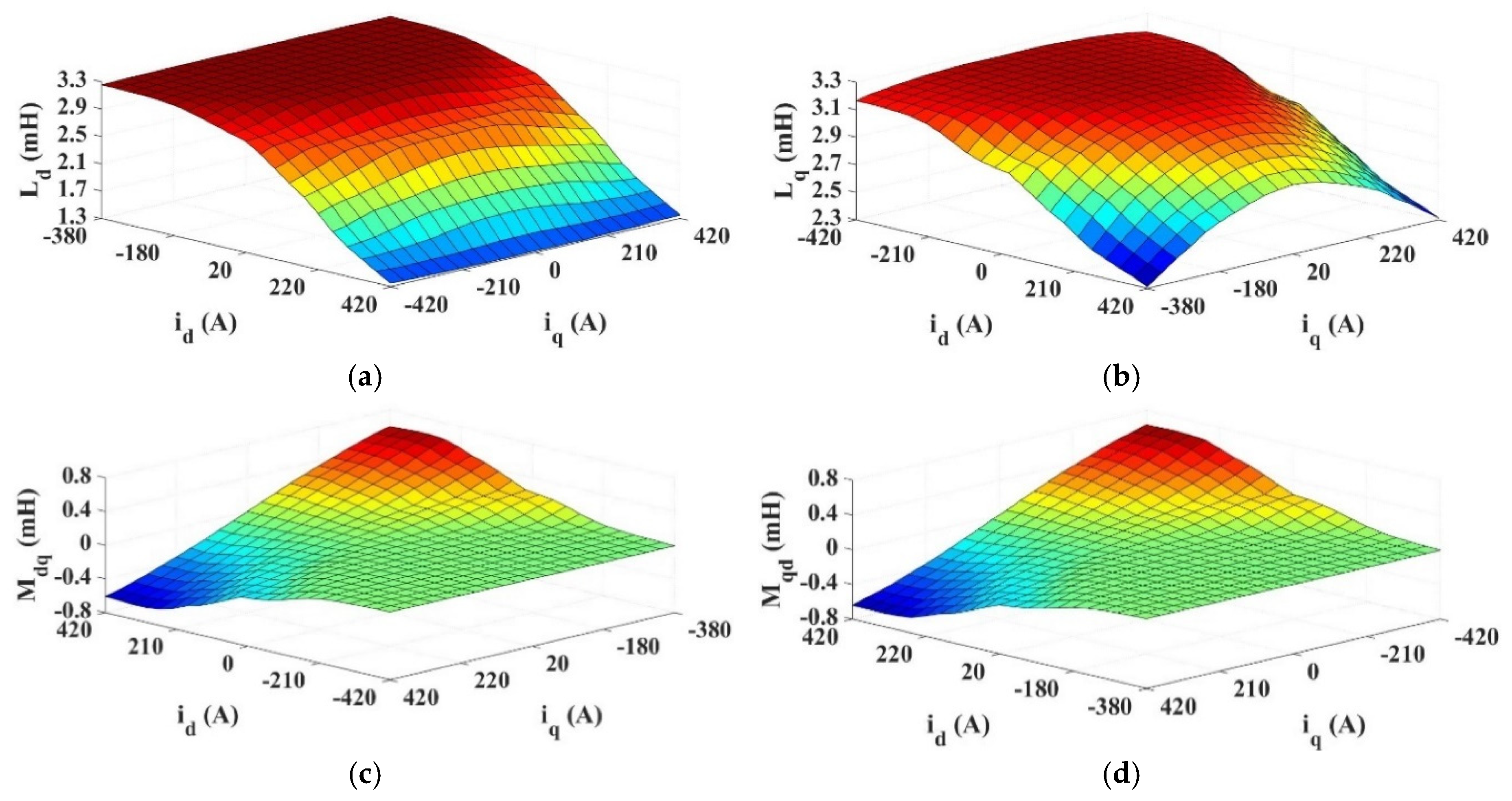
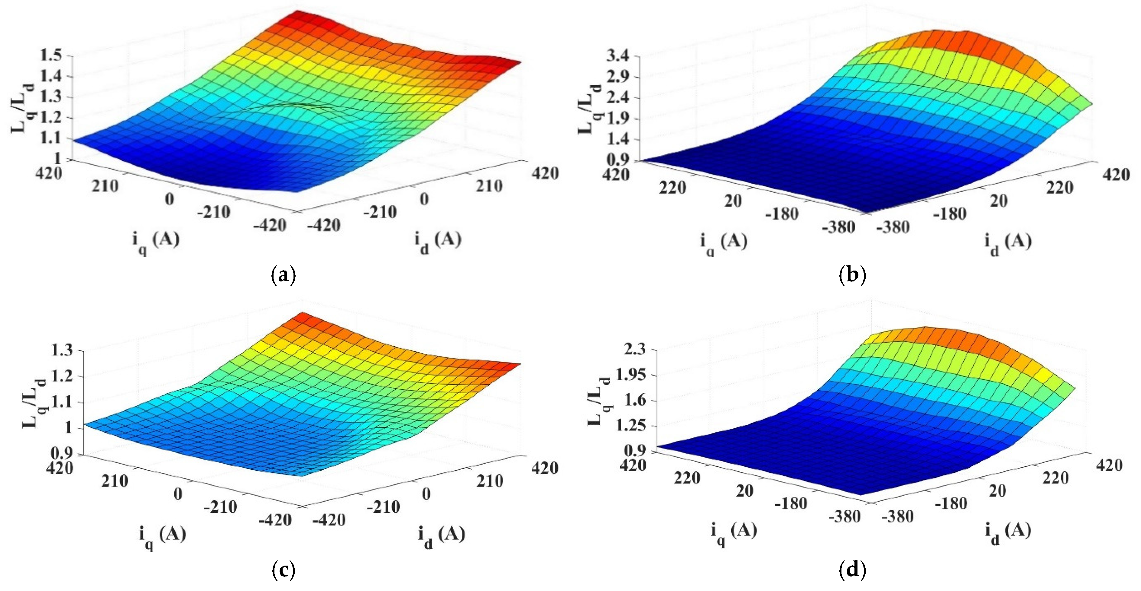
2.1. Model Setup and Inductance Calculations

To investigate the difference in saliency ratio between ISW and FSCW machines for use in offshore wind turbines, the baseline ISW and FSCW machines introduced in [15] are used in this paper. The parameters of the 480s/160p ISW machine (see Table 1) are used as a baseline for the investigation of both the 192s/160p FSCW and the 480s/160p ISW machines in this paper. It is worth noting that in [15], the machines have a dual three-phase winding structure. However, for simplicity in this investigation, the machines are operated as only single three-phase, and so the three-phase winding connections for the two machines can be seen in Figure 1.
As evidenced in the literature, magnetic saliency for an SPM machine comes from main flux saturation or flux leakage saturation. To better understand this in the 3 MW machines, the saliency ratios of both the 480s/160p and 192s/160p machines were investigated under a broad range of saturation conditions. Principally, the saturation of the d- and q-axes was caused by large d- and q-axis currents. As discussed above, the saliency ratio is given as a function of the d- and q-axis inductances, so these must first be obtained if the saliency of the machine is to be calculated. The machines were modelled in the OPERA 2D FEA software (version 2023) package and rotated through 60 elec. Deg. With the d- and q-axis currents sweeping from −420A to 420A each time. As in most FE modelling, the air-gap region is the most critical area, as its mesh size directly affects the convergence and accuracy of the results. To ensure accuracy while maintaining computational efficiency, we implement a two-layer mesh structure: one layer is attached to the stationary stator, while the other rotates with the rotor. The mesh size in the air-gap is determined using mesh size = 2πR/2p × 1/50, where R is the air-gap radius and p is the number of pole pairs. This results in a mesh size equal to 1/50 of the pole arc. This choice represents a trade-off between result accuracy and computational time, ensuring sufficient resolution for field variations while keeping the simulation efficient.
The d- and q-axis flux linkages of the machine could then be measured for each case, and the inductances were calculated by subtracting the d- and q-axis flux linkages [ ψ d ( i q , ψ p m ) and ψ q ( i d , ψ p m ) ] at i d = 0 and i q = 0 , respectively, from the d- and q-axis flux linkages [ ψ d ( i d , i q , ψ p m ) and ψ q ( i d , i q , ψ p m ) ] at i d 0 and i q 0 , respectively. This produced a 3D map of both self- and mutual inductances in the dq-frame based on the apparent change in inductance with applied current. The apparent inductances were calculated across all cases using the following equations:
L d = ψ d ( i d , i q , ψ p m ) ψ d ( i q , ψ p m ) i d
L q = ψ q ( i d , i q , ψ p m ) ψ q ( i d , ψ p m ) i q
M d q = ψ d ( i d , i q , ψ p m ) ψ d ( i d , ψ p m ) i q
M q d = ψ q ( i d , i q , ψ p m ) ψ q ( i q , ψ p m ) i d
where Mdq and Mqd are the mutual inductances between the d- and q-axes and ψ d and ψ q are the d- and q-axis flux linkages, respectively. The flux linkages are expressed as functions of the d- and q-axis currents and open circuit flux linkage ψ p m . These equations were used to produce 3D maps of inductance across all saturation conditions and can be seen for the 480s/160p and 192s/160p machines in Figure 2 and Figure 3.
It can be seen in both cases that a reduction in d- and q-axis inductance is more susceptible to an increase in d-axis current owing to the saturation of PM flux in the d-axis. It appears as though q-axis current has limited impact even on q-axis inductance. Furthermore, it can be seen that there is a discrepancy between the mutual inductances Mdq and Mqd, with the values of Mqd being much larger than Mdq for high d-axis currents. This is caused by the high levels of existing d-axis flux saturation caused by the PMs, which reduces the effect of cross-coupling flux induced in the d-axis by the q-axis current. However, the q-axis is not subject to the same level of PM flux saturation, and so the mutual inductance from the d- to the q-axis is much larger. To remove this discrepancy, the incremental inductances can be used instead of the apparent inductances. This method subtracts the flux linkage induced from the previous loading condition in an iterative process so that the change in flux can be more directly linked to the incremental increase in current. In doing so, the impact of saturation accrued by loading up to that point can be reduced. The equations for incremental inductance calculations are
L d = ψ d ( i d + i d , i q , ψ p m ) ψ d ( i d , i q , ψ p m ) i d
L q = ψ q ( i d , i q + i q , ψ p m ) ψ q ( i d , i q , ψ p m ) i q
M d q = ψ d ( i d , i q + i q , ψ p m ) ψ d ( i d , i q , ψ p m ) i q
M q d = ψ q ( i d + i d , i q , ψ p m ) ψ q ( i d , i q , ψ p m ) i d
These equations were applied to produce plots of incremental inductances for the 480s/160p and 192s/160p machines and are given in Figure 4 and Figure 5.
The same trend of d-axis current on both d- and q-axis inductance can be seen for incremental inductance as with apparent inductance, although the magnitude of inductance decrease for high currents has increased. However, the q-axis inductance shows a more substantial decrease with high q-axis currents, as would be expected. The use of incremental inductance has also produced plots for Mdq and Mqd that are equal. This aligns better with the understanding of how the inductances should vary under different d- and q-axis loading conditions. With both apparent and incremental inductances calculated for both the ISW and FSCW machines, maps of the saliency ratio can be produced and are given in Figure 6.
With these results, the difference between the calculation of apparent inductance and incremental inductance can be seen. The cross-coupling saturation from the d- to the q-axis is not properly accounted for in the apparent inductance, which leads to a saliency ratio that slightly increases for large q-axis currents in both the ISW and FSCW machines. The incremental inductance shows the expected results, where a large d-axis current substantially increases saliency ratio and there is a reduction when large q-axis currents are applied. For both the ISW and FSCW machines, the change in saliency ratio with the q-axis current is plotted for three d-axis currents, id1, id2, and id3, which are d-axis currents of −420A, 20A, and 420A, respectively. This should highlight saliency performance under different conditions, i.e., when the PM flux is essentially reversed by a large negative d-axis current (id1), when there is only a small d-axis current (close to normal operation, id2), and extreme d-axis saturation under high d-axis current (id3). For example, the results for incremental saliency ratios can be seen in Figure 7.
Although the two plots show a different relationship between the saliency ratio and q-axis currents, they both show the same undeniable relationship between the saliency ratio and d-axis currents. For both apparent and incremental inductances, when a large negative d-axis current is applied such that the PM flux is opposed, the saliency ratio is around one. When the d-axis current is brought to 20 A such that the PM flux is no longer opposed, the saliency ratio of the 480s/160p machine increases to about 1.2, while the saliency ratio of the 192s/160p machine does not increase much at all. Finally, when a large d-axis current of 420 A is applied, the saliency ratio of the 192s/160p machine is finally increased to above 1.2 and the saliency ratio of the 480s/160p machine increases even further. This validates the theory that the saliency of the ISW machine is attributed to main flux saturation.

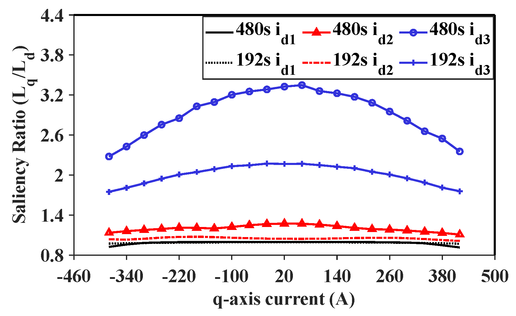
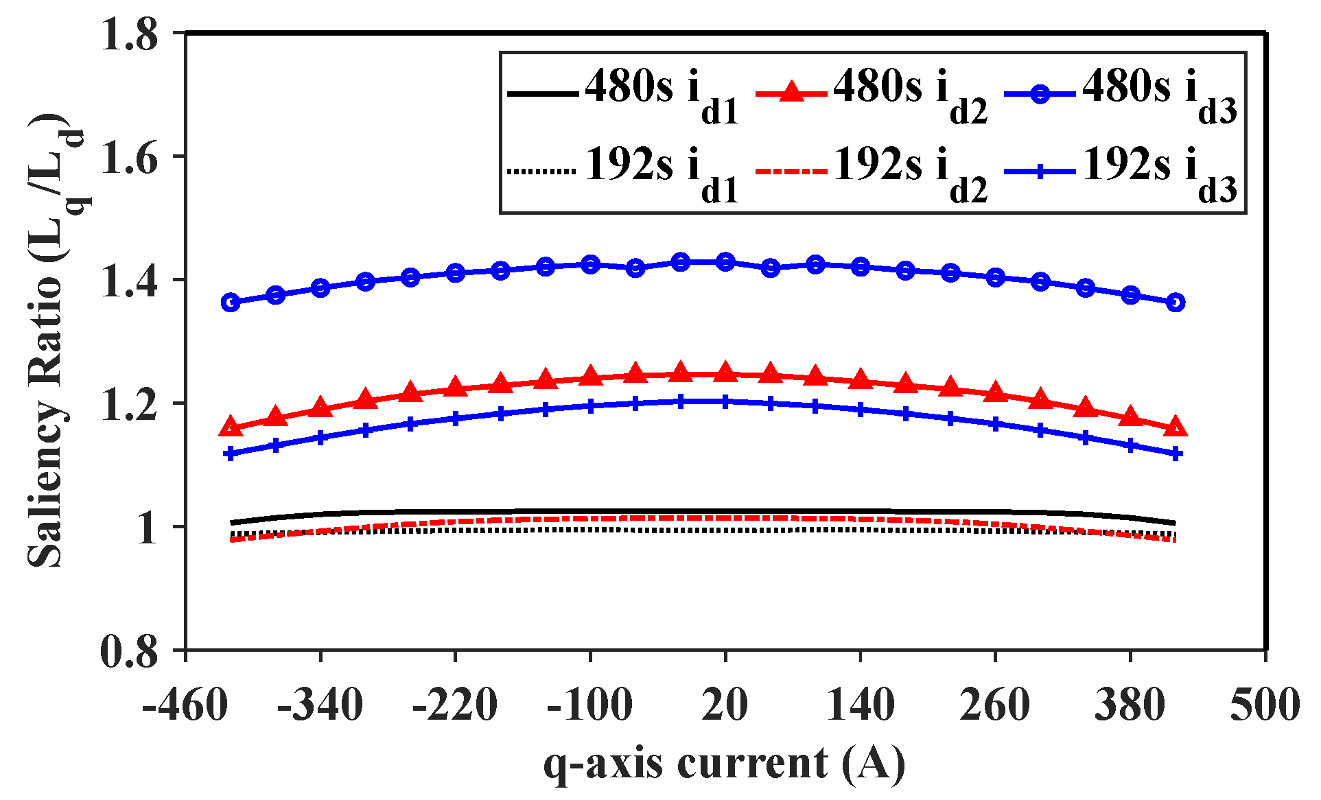
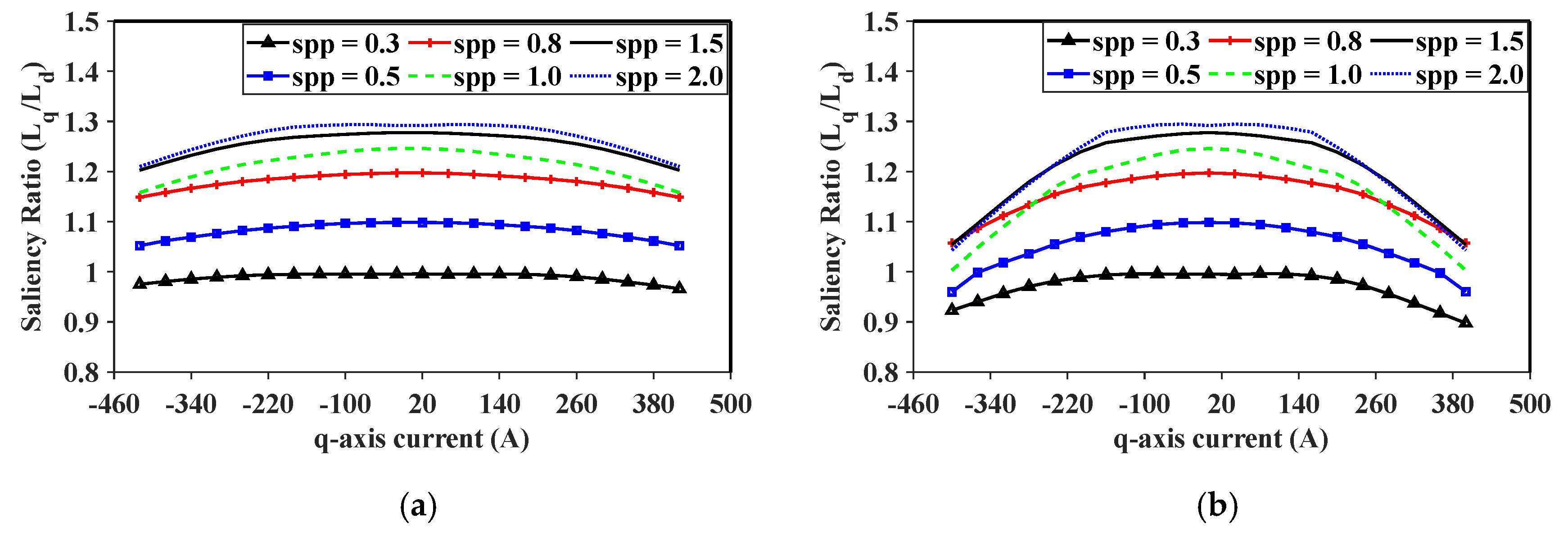
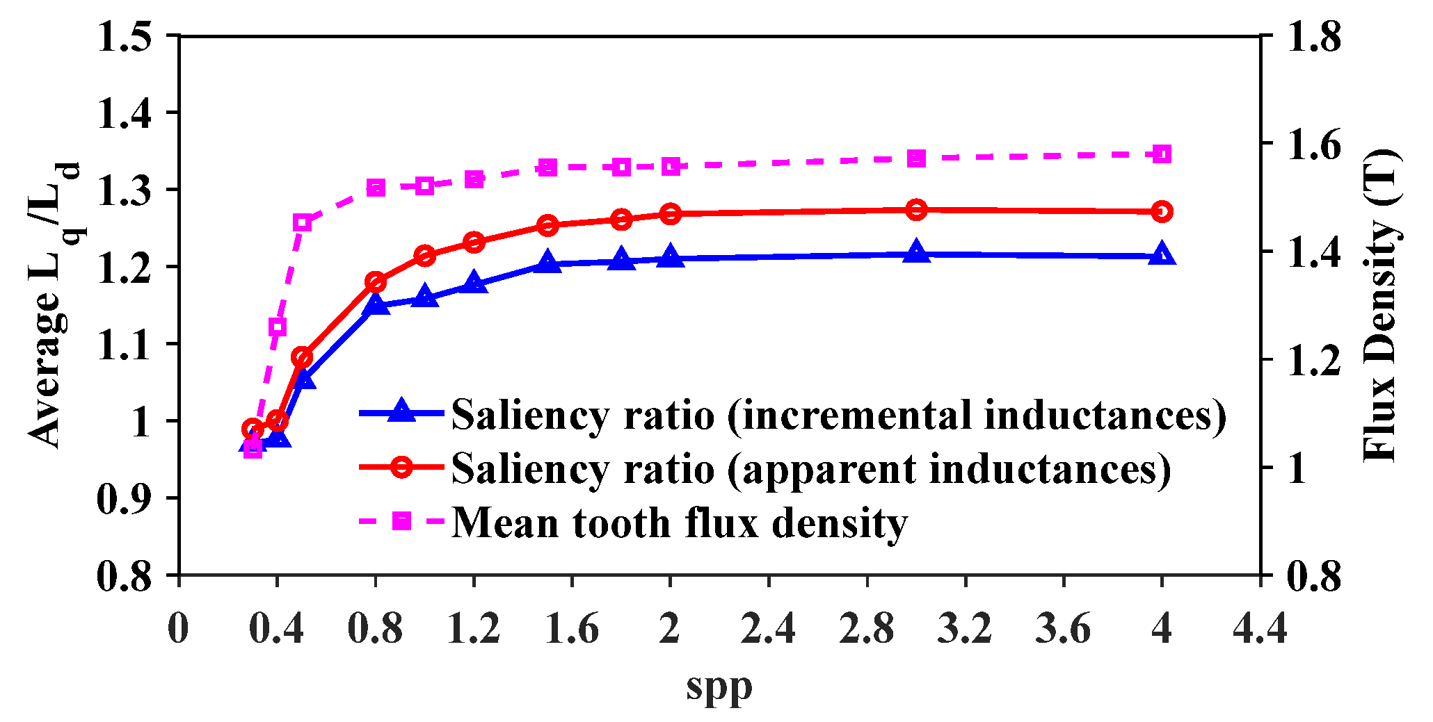
2.2. Saliency of Different Slots per Pole per Phase (Spp) Ratios

The results from the previous section do well to highlight the impact of d-axis saturation on increasing saliency ratio. However, calculations using the apparent inductance suggest that the saliency ratio also increases for large q-axis currents. This is caused by the failure of this calculation method to account for cross-coupling and can be amended by making a minor modification. Instead of calculating the d-axis inductance for each change in q-axis loading, it can be determined once using a small d-axis current with no q-axis current, and this value can then be used to calculate the saliency ratio across a q-axis current sweep. The results for this modification on the calculation of apparent saliency ratio across the three d-axis currents from before (−420 A, 20 A, and 420 A) can be seen in Figure 8.
These results are now much more representative of how the saliency ratio should reduce with q-axis saturation. As it has been established that the main flux saturation of the 480s/160p machine is what provides a large saliency ratio, it was decided to investigate a number of alternative slot–pole number combinations. Specifically, the previous inductance sweeps and saliency ratio calculations were applied to a number of similar 3 MW machines with a sweep of slots per pole per phase (spp) ranging from 0.3 to 4.0. The specifics of these machines can be seen in Table 2.
For the following results, a single d-axis inductance was calculated for a low d-axis current and used for all values of q-axis current. This was to reflect the real-world application of these machines in offshore wind power where a large d-axis current is not used. The results for both apparent and incremental saliency ratio sweeps can be seen in Figure 9.
Furthermore, in each case, the average flux density was measured within the centre of the teeth to see the relationship between the flux density within the teeth and the saliency ratio. The results for both apparent saliency ratio and incremental saliency ratio plotted with this average tooth flux density can be seen in Figure 10, with the flux density plots for a few example machines given in Figure 11.
It has been fully validated and established that the low saliency ratio of the 192s/160p FSCW machine is caused by the lack of main flux saturation in the stator teeth. It can be seen that by moving to a higher spp number the saliency ratio of the 3 MW machine would be enhanced. For example, a 384s/160p machine has an spp number of 0.8 and has a saliency ratio of about 1.19 when incremental inductances are used. Work in [15] has shown that this slot–pole multiple is competitive with the baseline a 480s/160p machine, and here it is shown that it also does not suffer from a lack of saliency. However, with a coil pitch of 2, it does not maintain concentrated windings, and so this paper will continue to investigate methods for improving the saliency ratio of the 192s/160p machine.

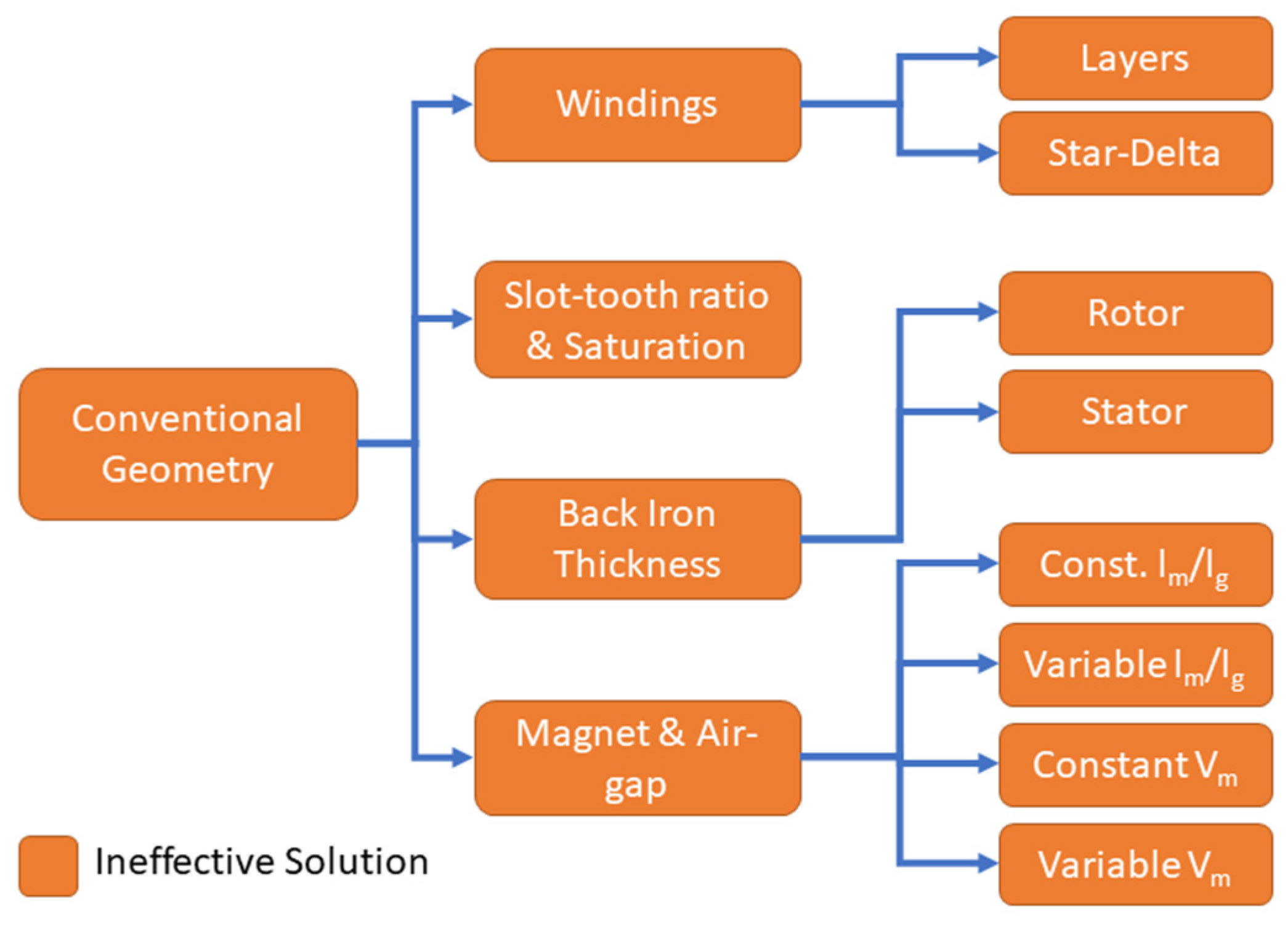
3. Conventional Geometry Modification
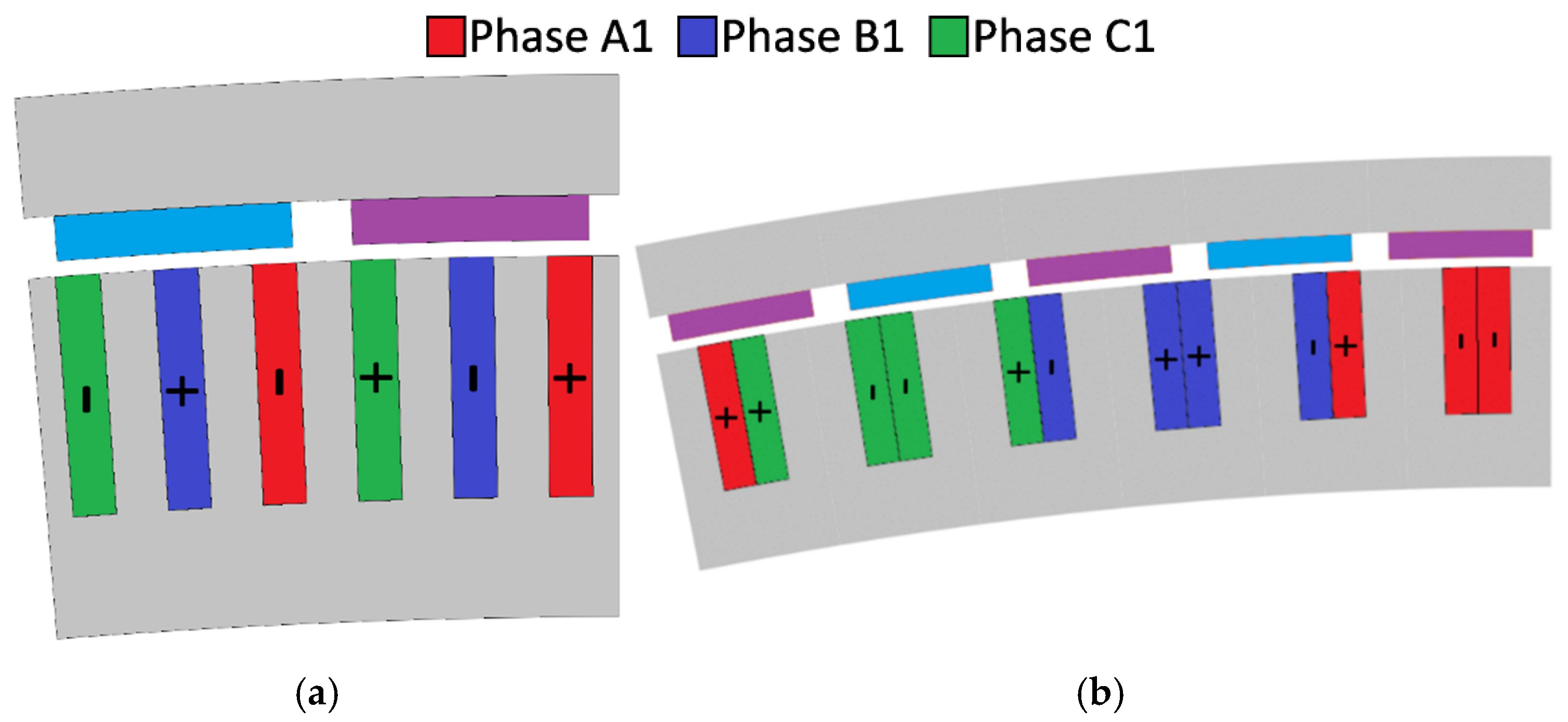
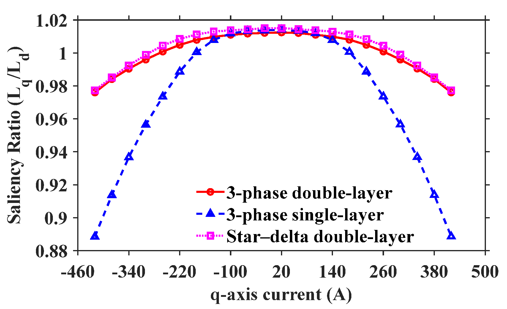
For direct-drive wind turbine generators, the SPM machine is favourable due to its large air-gap flux density, relative simplicity, and ease of manufacturing when compared with an IPM machine. To try and maintain this simple and effective machine structure, an investigation into a way of improving machine saliency while maintaining conventional geometry was carried out. This means only existing parameters within the SPM structure, like slot–tooth ratio and winding structure, are investigated in this section. It is worth noting that stator teeth are not used in large-scale wind turbine generators due to the challenges they pose in the machine winding process. Therefore, they are not included in this section but are examined in Section 4, where machine structure modifications are discussed. A breakdown of the investigation into conventional geometry can be seen in Figure 12. It can be seen that none of the investigations that maintained conventional geometry were able to effectively increase the saliency ratio; however, the results of each study are still briefly documented in this section.

3.1. Winding Layout

The only way to alter machine performance without even a slight alteration of the magnetic circuit of a machine is through the winding layout. As the constraint of the slot–pole ratio is already present, all that can be performed is to investigate the number of winding layers or the star–delta connection as investigated in [15]. A sweep of saliency ratios across q-axis currents was conducted for a 192s/160p three-phase machine with single-layer windings. It was demonstrated in [16] that the star–delta connection was able to improve the saliency ratio of an FSCW SPM machine by 1.2%, so it was worth investigating if a similar increase could be gained for a large-scale machine. The winding layouts for the 192s/160p three-phase machine with single-layer windings and star–delta windings are given in Figure 13, and a comparison of the saliency ratios of the three investigated winding connections can be seen in Figure 14. It is important to note that in a conventional 192s/160p machine (see Figure 13a), the coil EMF vectors of the same phase exhibit a 30° electrical phase shift. Consequently, connecting them in series reduces the winding distribution factor and, thus, the overall winding factor. To compensate for this reduction, a dual three-phase winding structure—supplied by two separate inverters—can be employed, where the second inverter is phase-shifted by 30° relative to the first. Alternatively, if a single inverter is preferred, a star–delta winding connection, as illustrated in Figure 13b,c, can be adopted. In this configuration, the delta coils inherently introduce a 30° phase shift compared to the star coils of the same phase, effectively emulating the effect of a second inverter with a 30° phase shift. However, since the delta coil current is (1/ 3 ) times that of the star coils, the number of turns in the delta winding must be increased by a factor of 3 to maintain the same MMF. Beyond improving the fundamental winding factor, the star–delta connection also significantly suppresses subharmonics; further details are provided in [16].
It is clear that altering the winding connection will not lead to an increase in the saliency ratio. The star–delta connection is able to improve the saliency ratio by 0.3% for low q-axis currents, but this is much too small to yield a tangible difference for sensorless control. Furthermore, this increase diminishes at high q-axis currents. The saliency ratio of the single-layer windings is within 0.1% of the double-layer windings for low q-axis currents and then drops substantially at higher currents. As a single-layer winding has twice the number of turns wound around an individual tooth when compared with a double-layer winding, this is an expected result. At higher q-axis currents, the teeth in the single-layer-wound machine saturate much more quickly, and there is a sharp reduction in saliency ratio owing to the reduction in q-axis inductance. It can be concluded that the winding connection cannot be used to improve the saliency ratio of the proposed FSCW machine.

3.2. Slot–Tooth Ratio

It has been evidenced in Section 2.2 that the saliency of the higher-spp machines comes from the saturation of flux within the stator teeth. Thus, it stands to reason that the simplest way to improve the saliency ratio of the 192s/160p machine is to adjust the slot–tooth ratio, i.e., β. However, by increasing the tooth saturation in this manner, it is expected that there will be a substantial reduction in torque performance. OPERA 2D was used to run a full q-axis sweep for a range of β values and compare them with the resulting torque performance of the machine. The results of this study can be seen in Figure 15.
The baseline slot–tooth ratio, taken from Table 1, is 0.45, which results in an average torque of just over 1.6MNm for the 3 MW FSCW machine. In order to reach a saliency ratio of 1.2, the slot–tooth ratio would need to reach 0.72, for which the torque performance would drop to below 1.2MNm. Although there would be a reduction in copper losses, a 25% reduction in torque, and therefore power, would drastically reduce the effectiveness of FSCW machines for use in offshore wind power. Thus, it can be concluded that this is an ineffective method for increasing the saliency ratio of the proposed machine.

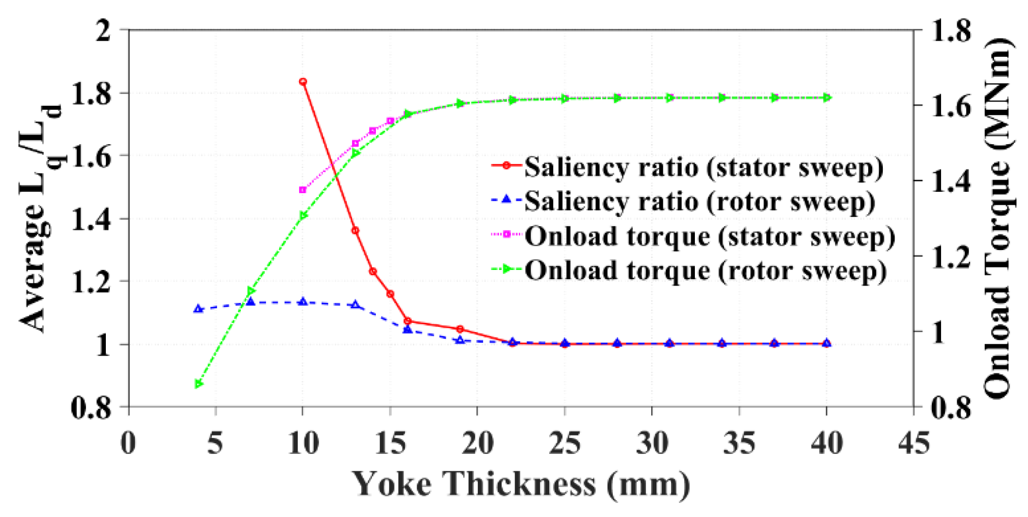
3.3. Back-Iron Thickness

If saturation induced in the stator teeth can yield an increase in saliency ratio, then it follows that saturation induced in either the stator or rotor yoke could also be used to affect the saliency ratio. Much like in the previous section, saliency ratio sweeps were conducted for a range of q-axis currents across a range of stator and rotor yoke thicknesses. The baseline yoke thickness for both stator and rotor is 40 mm, and this was reduced either until the saliency ratio surpassed 1.2 or the yoke became too thin to sustain even 1MNm of average torque. The comparative results of saliency ratio sweeps and corresponding torque results can be seen in Figure 16.
It can be seen that it is not possible to achieve a saliency ratio of 1.2 through a reduction in rotor yoke thickness. This is in addition to a large reduction in onload torque capability and reduced rotor yoke thicknesses. By reducing the stator yoke thickness to 14 mm, it is possible to achieve a saliency ratio of 1.2. However, this comes at a 5.4% reduction in torque performance. This is a more promising solution than the use of the slot–tooth ratio to increase the saliency ratio but is still too much to be considered an effective solution.

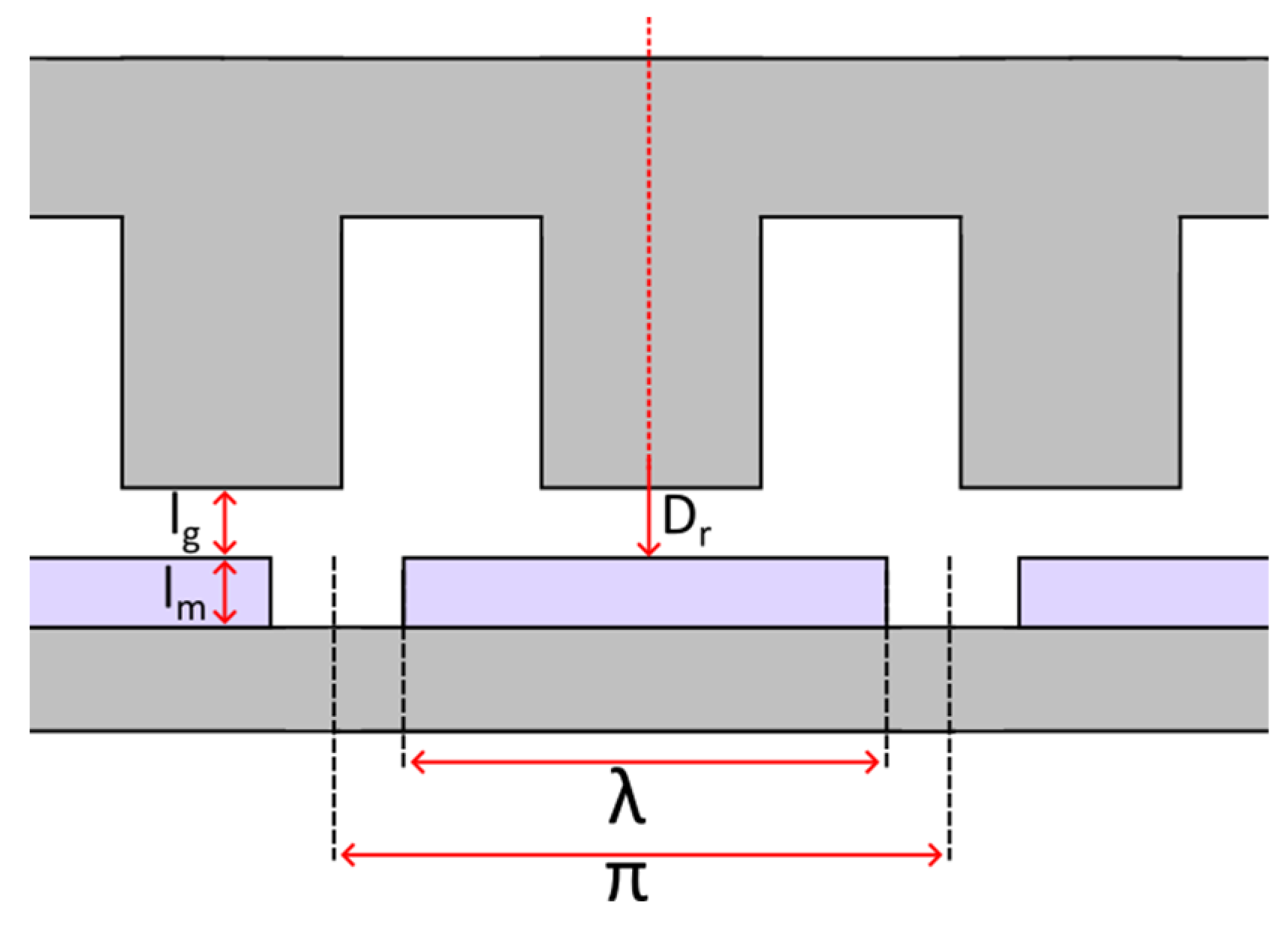
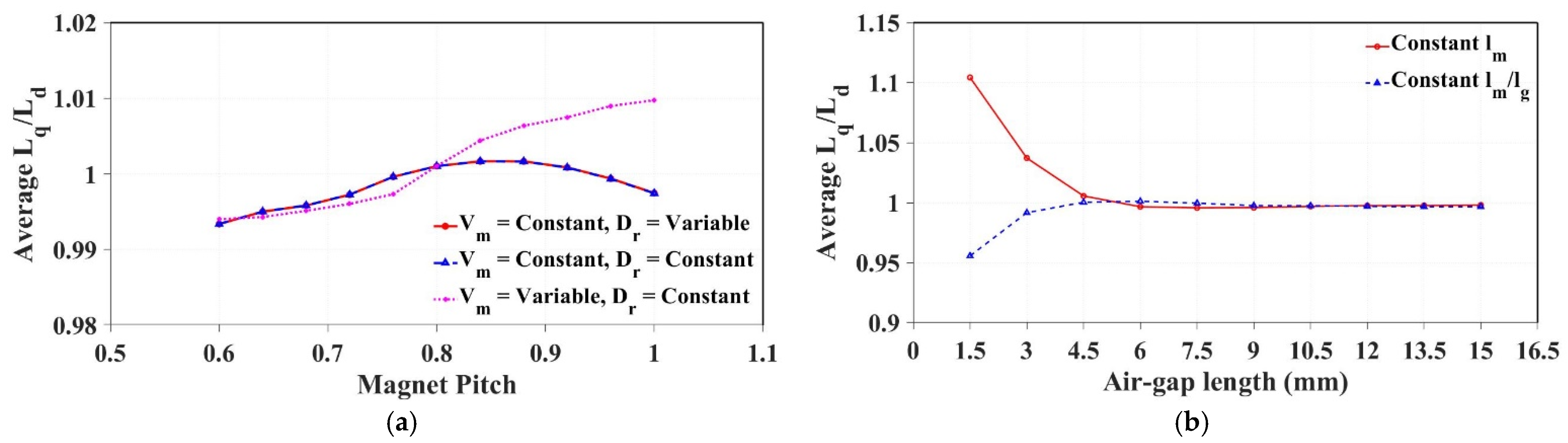
3.4. Magnet and Air-Gap Dimensions

There are two investigations in this section: one for the impact of magnet pole arc on saliency ratio and a second for air-gap length. These investigations have been grouped together, as the ratio of magnet height to air-gap length ( l m / l g ) is a key design criterion for electrical machines that can be used to approximate air-gap flux density. The investigation into magnet pole arc is split into three studies so that a full range of magnet dimensions and associated l m / l g can be understood. For the first study, the magnet volume and air-gap length are kept constant such that the rotor diameter is variable. For the second study, the magnet volume and rotor diameter are kept constant such that the air-gap length is variable. Finally, for the third study, the magnet volume is variable such that both rotor diameter and air-gap length are constant. The investigation into air-gap length only has two studies. In the first study, the length of the magnet is constant such that the ratio l m / l g is variable. For the second study, the length of the magnet is variable such that l m / l g remains constant. A diagram showing these dimensions for the 192s/160p machine can be seen in Figure 17, and the results of the investigations are found in Figure 18.
It can be seen that none of the investigations in this section were able to achieve a saliency ratio of above 1.2. The magnet pole arc, regardless of any other dimension, appears to have no impact on machine saliency at all. This is because NdFeB has a relative permeability that is very close to 1 and thus does not change the magnetic circuit at all. The case with an air-gap length of 1.5 mm and a constant magnet height achieves a saliency ratio of 1.1 due to increased saturation in the stator teeth. However, for a machine with a 5 m rotor diameter, a 1.5 mm air-gap length is unfeasible, and so it is not a possible solution for increasing the saliency ratio of the investigated machine.

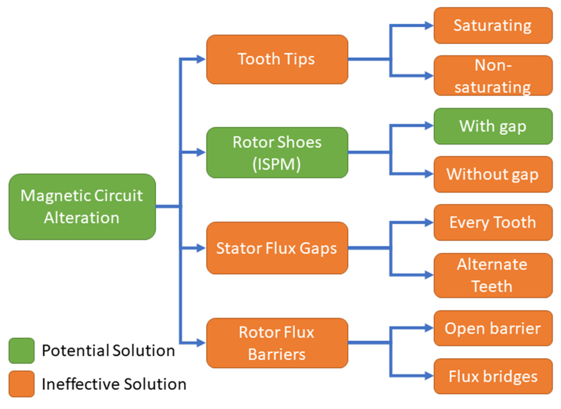
4. Magnetic Circuit Alteration

It is clear that it is not possible to design a 3 MW FSCW machine with conventional geometry to achieve a saliency ratio of 1.2 without a substantial reduction in torque performance. Therefore, this section looks at a range of methods to alter the magnetic circuit of the 3 MW machine to increase the saliency ratio. A breakdown of this investigation can be seen in Figure 19.
It can be seen that the majority of studies carried out in this section did not offer potential for saliency enhancement of the 3 MW FSCW machine. However, they are still documented briefly in this section. The addition of rotor shoes appeared to offer the most promising increase in saliency ratio enhancement without too much impact on torque performance, and so this option is studied in more depth in Section 5. In this investigation, material conductivities were set to zero to isolate the effect of magnetic saturation on torque performance. This allowed us to focus solely on this aspect and ignore how the altered circuit might affect eddy current losses. If a promising solution arose, we could reintroduce material conductivity to account for eddy currents. Given the options for eddy current reduction, like insulated laminations or soft magnetic composites, this seemed like a logical approach as they could then be dealt with after a promising solution was selected.

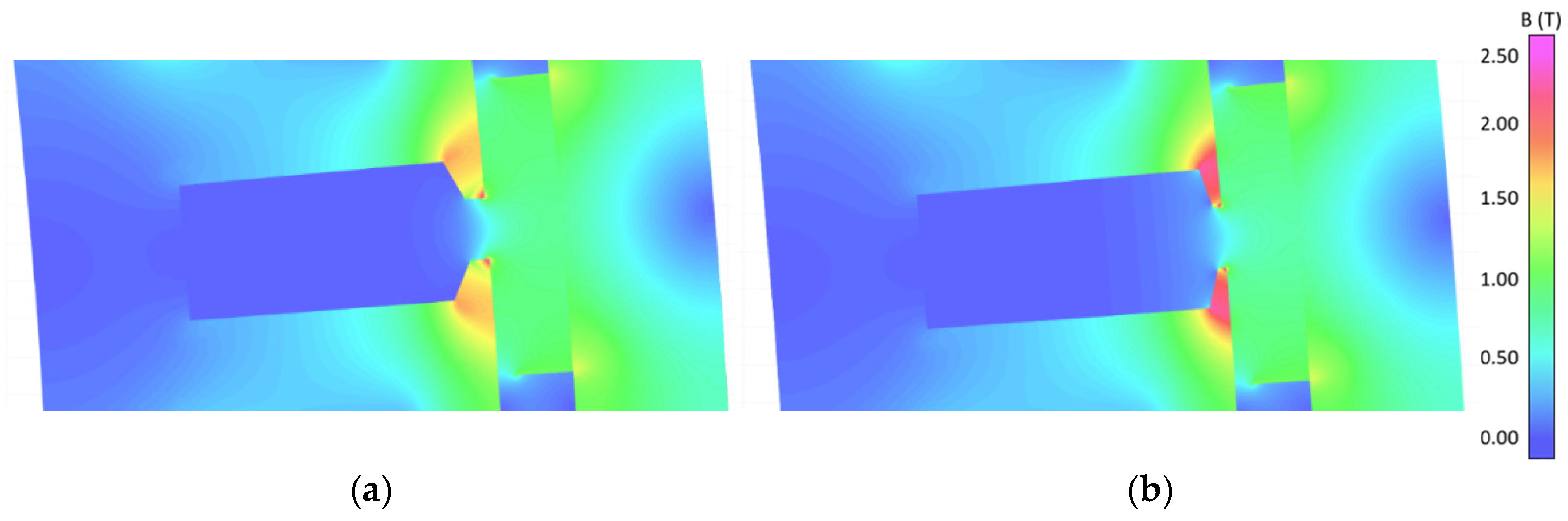
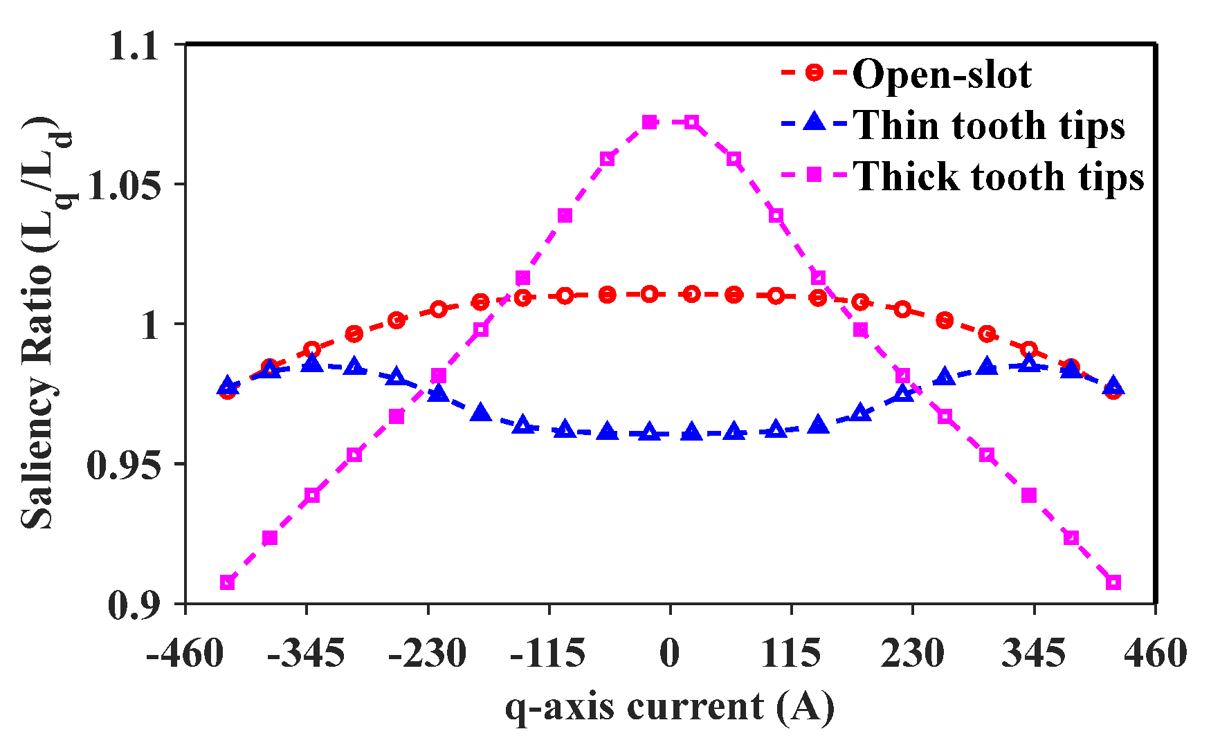
4.1. Addition of Tooth Tips

In the literature, it was highlighted that tooth tips could be used to alter the saliency ratio of FSCW machines [3,10]. This is accomplished by using tooth tips to capture ‘zigzag’ leakage flux from the PMs as they pass between stator teeth. The maximum point of q-axis current within a coil is when it is between two poles of a pole pair, which is 90° from the d-axis. If tooth tips are introduced, then they assist in capturing flux from the PMs at this point and, depending on the flux saturation in the tooth tips, can either increase or decrease saliency ratio. A diagram that demonstrates this maximum q-axis point can be seen in Figure 20.
In [10], the tooth tips are designed such that they cause a high level of flux saturation, thus reducing q-axis inductance. Although this method reduces the saliency ratio, the key parameter for sensorless control is the difference between d- and q-axis inductances. So, even with a q-axis inductance lower than the d-axis inductance, a saliency inverse can be applied that yields a machine with an inversed saliency ratio of 1.2. In this section, two types of tooth tips are briefly studied: those that overly saturate the q-axis flux and those that do not cause excessive flux saturation. The PM flux saturation within both types of teeth investigated can be seen in Figure 21, with the results of the investigation given in Figure 22.
As expected, the thin stator tooth tips cause a large amount of q-axis saturation at low q-axis currents, which reduces the saliency ratio to below 1. The thicker stator teeth, which do not cause excessive saturation at low q-axis currents, yield an increase in saliency ratio for low q-axis currents. Then, as the q-axis current increases, it leads to saturation even within the thicker teeth such that the inductance begins to decrease more rapidly. The thin stator teeth appear to yield a similar saliency ratio to the open-slot scenario for overload q-axis currents. At these high q-axis currents, the flux density within the tooth tips reached 2.5 T and was constrained by the OPERA software not to exceed this value. Thus, it essentially removed the tooth tips from the circuit and impeded any additional q-axis saturation. It is clear that both thick and thin tooth tips can be used to alter the saliency ratio of the proposed machine. In particular, the thick tooth tips yield an increase in saliency ratio and should also lead to an increase in torque performance through the capacity to capture more PM flux. However, tooth tips add a substantial manufacturing complexity to large offshore wind turbine generators. Due to this fact, and despite the potential benefit of this topology to torque performance and saliency ratio, this investigation was not pursued further.

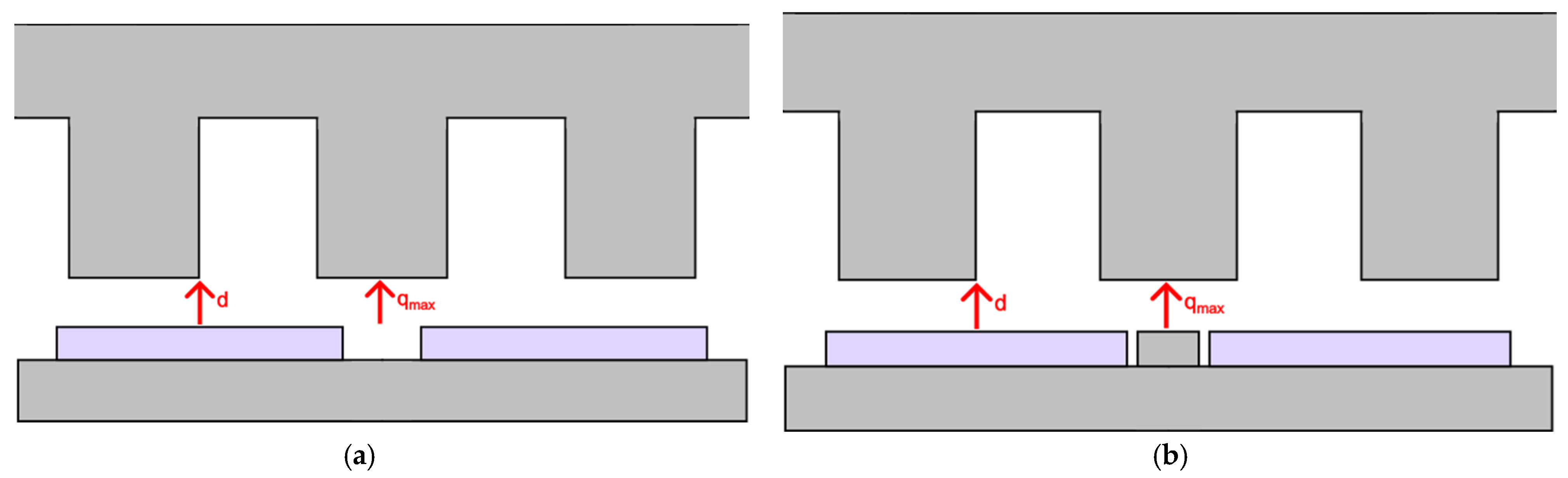
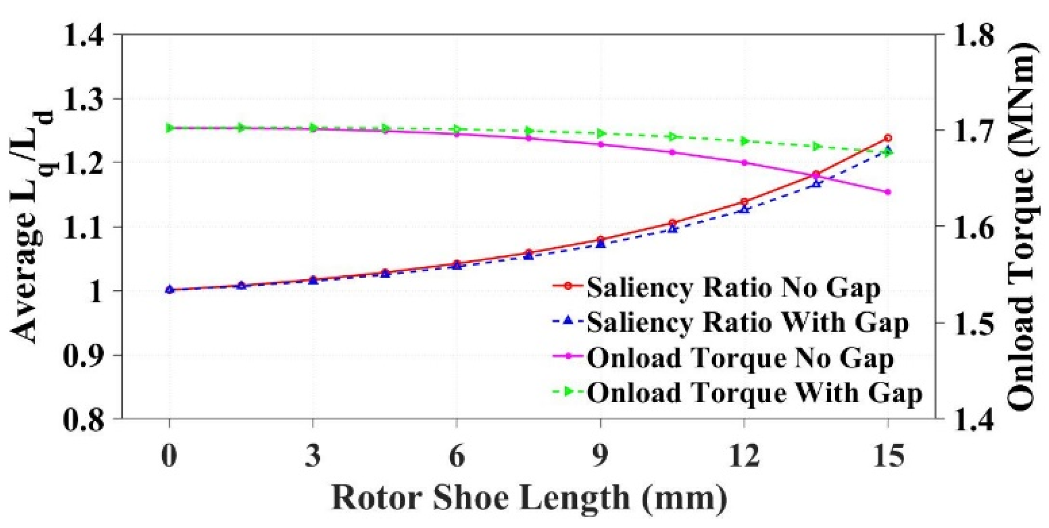
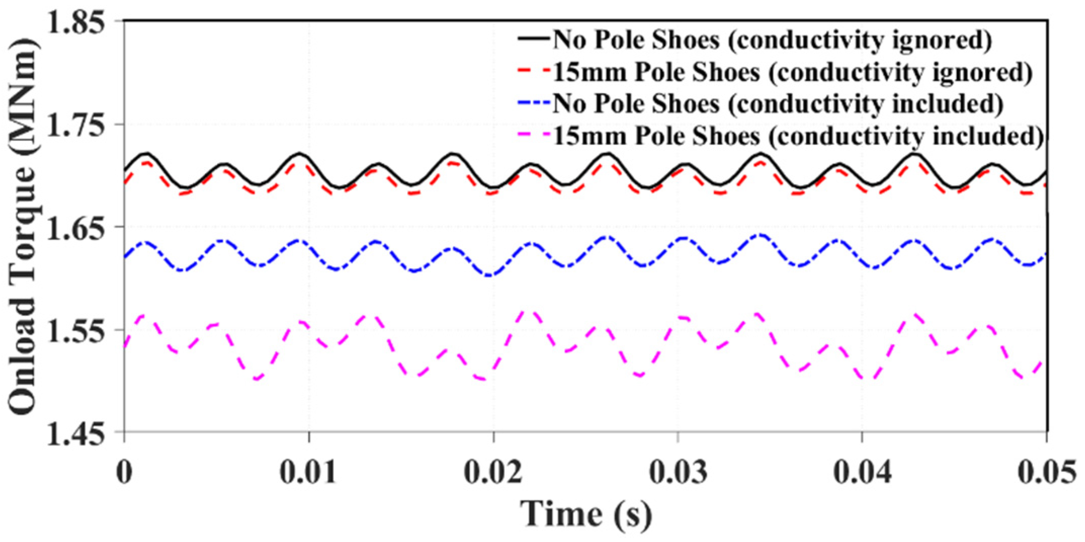
4.2. Addition of Rotor Shoes

As discussed in the literature, the saliency ratio of SPM machines can be improved through the addition of rotor shoes [12,13]. These shoes sit between the PMs and essentially reduce the reluctance of the q-axis, therefore increasing q-axis inductance and saliency ratio. It has been demonstrated that this method can reliably increase the saliency ratio of FSCW machines but at an unfortunate reduction in electromagnetic performance. A diagram demonstrating the addition of rotor shoes between the PMs can be seen in Figure 23.
The addition of rotor shoes of varying heights was investigated once again using OPERA. Initially, two different shoe types were studied: one where the PMs are fully inset into the rotor shoes and one where a small air-gap is present between the iron and PMs. The results of both these studies for increasing shoe height can be seen in Figure 24.
The inclusion of rotor shoes has had an expected impact on machine saliency, with rotor shoes of 15 mm successfully increasing the saliency ratio of the FSCW machine to above 1.2. It is clear that the reduction in torque is minimized when there is a small air-gap between the PM and rotor shoe. Provided that eddy currents are ignored, it is possible to achieve a saliency ratio of 1.2 with rotor shoes 15 mm high while only suffering a 0.5% reduction in average torque. However, this is an ideal scenario, and so a true measure of torque performance can only be gained by reintroducing conductivity and comparing, as can be seen in Figure 25, with a direct comparison of torque results given in Table 3.
It is unfortunate that the inclusion of eddy currents drastically reduces the effectiveness of the rotor shoes when considering electromagnetic performance. With no material conductivity, the average torque of the 192s/160p machine with 15 mm pole shoes is only 0.5% less than the conventional 192s/160p machine. With conductivity included in the model, this difference is increased to 5.4%. This is not an acceptable reduction in torque performance; however, with optimization, this reduction could hopefully be minimized, and this is what is considered in Section 5. In addition, it is worth noting that this study was based on solid rotor iron core; if laminated iron core (with increased manufacturing complexity) was used, the rotor eddy current loss would be significantly reduced.

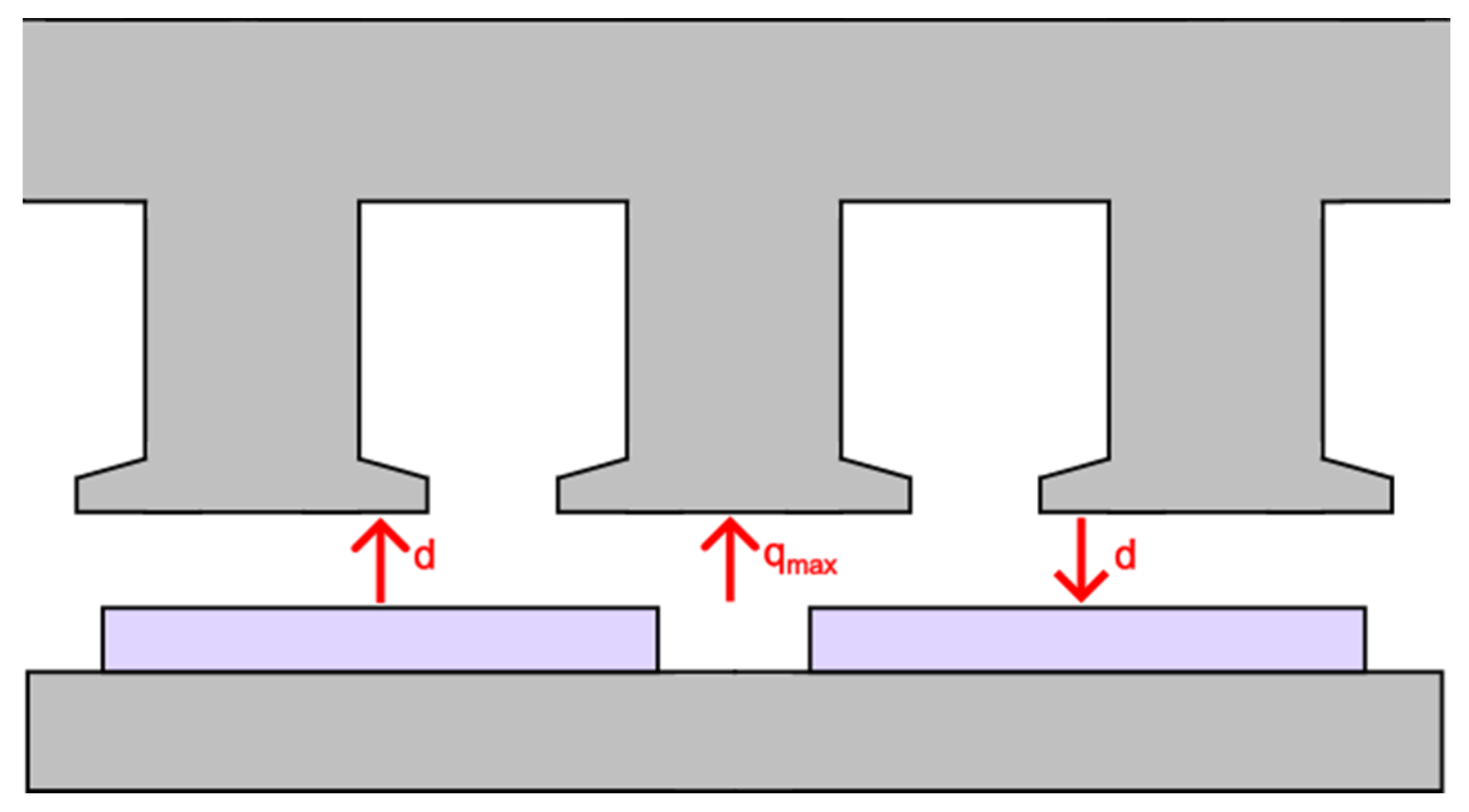
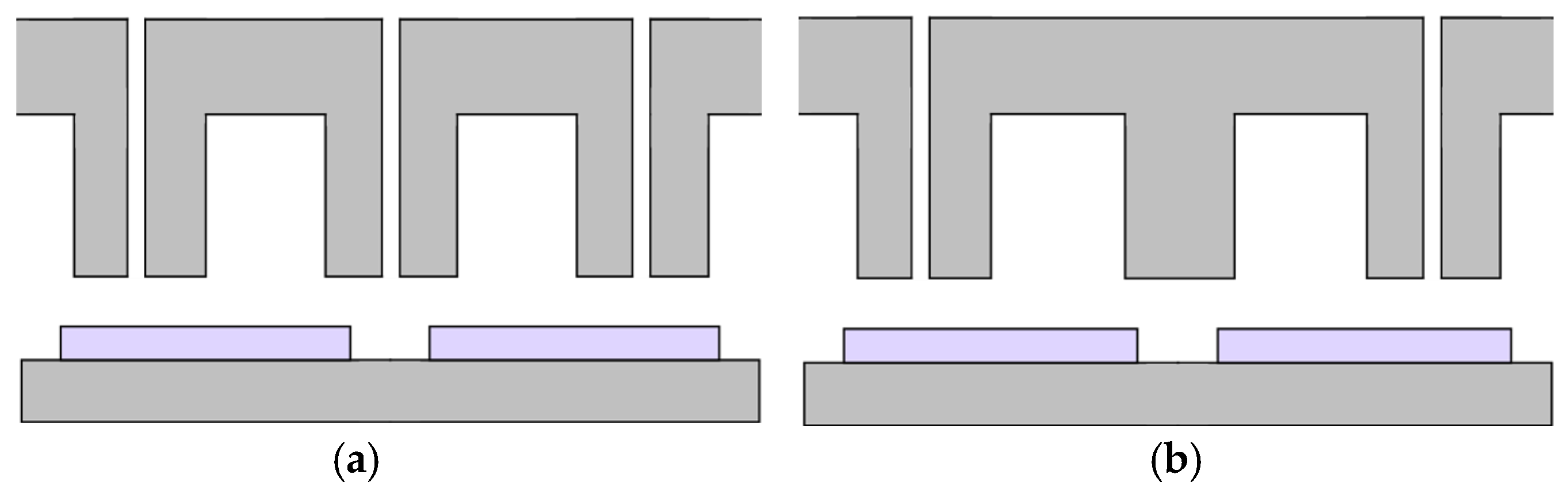
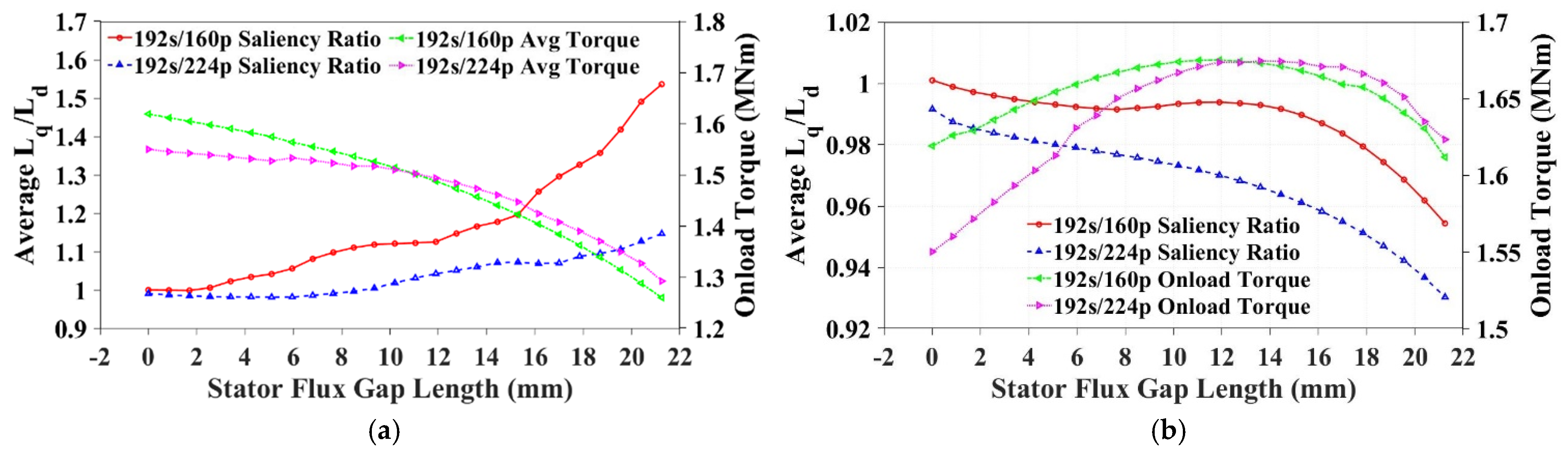
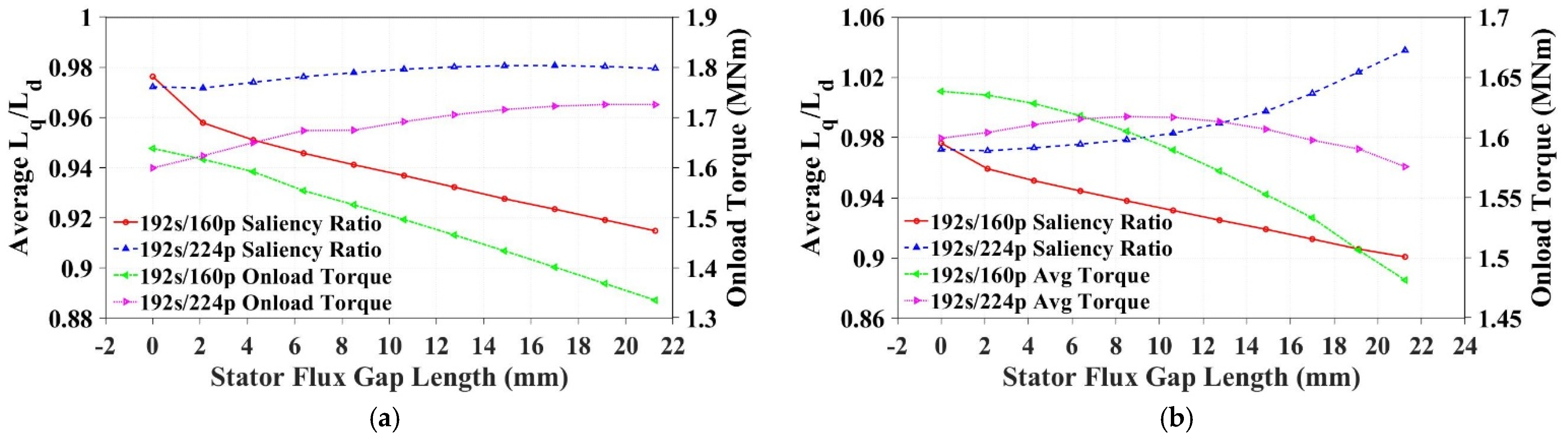
4.3. Stator Flux Gaps

As discussed in [17], modular FSCW machines with flux gaps between stator teeth have shown that they can affect machine electromagnetic performance. One of the reasons for this is a flux focusing or defocusing effect that depends on the slot–pole ratio selected. As the work in [17] investigates the impact of flux gaps on both 12s/10p and 12s/14p designs, this section will extend the study to both 192s/160p and 192s/224p machines. Although it has been identified in Section 2.2 that a 192s/224p machine is likely to have a lower saliency ratio than a 192s/160p machine with an spp number of 0.286, in [17] it is identified that this topology gains more from the inclusion of flux gaps. In addition to the two slot–pole ratios investigated, two different flux gap designs are studied. Firstly, flux gaps in every tooth are investigated that create ‘C-core’ stator iron segments [18]. This is then followed by mirroring the work in [17] and investigating flux gaps in every other tooth known as ‘E-core’ iron segments. For the E-core iron segments study, the winding structure was modified to a single-layer winding, as this is better suited to the flux gaps in alternate teeth owing to the ease of manufacture. For each of these studies, the increasing flux gap width is studied both for constant copper area and constant tooth area. The investigation with constant copper area will present a change in saliency ratio as a focus of combined flux focusing/defocusing as well as increasing tooth saturation while maintaining constant copper losses, whereas the investigation with constant tooth area will isolate the impact of flux focusing/defocusing on saliency ratio while increasing the copper loss of the machines. The two different types of flux gaps investigated in this work can be seen in Figure 26.
The results of the saliency ratio sweep on increasing flux gap width in every tooth can be seen for both the constant copper and constant tooth width cases in Figure 27.
For the case of constant copper area, the increasing flux gap width serves to increase the saliency ratio of both the 192s/160p and 192s/224p machines, though the rate of increase is much higher for the 160-pole machine. This can be attributed to the reduction in tooth area and therefore increase in main flux saturation that has already been seen in Section 3.2. Although an increase in saliency ratio is achieved, the reduction in onload torque is once again too large to be considered a viable solution. For the scenario with constant tooth area, there appears to be a saliency inverse effect in both the 192s/160p and 192s/224p machines with increasing flux gap width in addition to an increase in onload torque. This phenomenon has been investigated in [18], where the flux gaps in C-core segments serve to initially increase the fundamental flux linkage before they become too wide and cause flux defocusing. By increasing the fundamental flux linkage, the d-axis inductance is increased in addition to the onload torque, resulting in a decrease in saliency ratio. However, even with the most extreme case observed in the 192s/224p machine, the resulting inversed saliency ratio Ld/Lq is 1.09, which is still not enough for sensorless control. While the impact of flux focusing on torque performance is an interesting avenue for research, it is not the main focus of this work and so will not be pursued further. The results for the same saliency ratio sweep with increasing flux gap width in alternate stator teeth and single-layer windings can be seen for the constant copper and constant tooth width scenarios in Figure 28.
The results in Figure 28a mirror the results obtained in [17]. The 192s/160p machine has a reduction in the pitch factor and flux defocusing with increasing flux gap width, leading to a reduction in torque performance. This flux defocusing also contributes to a reduction in q-axis inductance that reduces saliency ratio. The pitch factor of the 192s/224p machine increases with increasing flux gap width owing to the closer alignment of coil pitch to pole pitch and added flux focusing effect. This leads to a slight increase in the saliency ratio of the 224-pole machine. However, once again, there is not a large enough difference in saliency ratio to consider this a viable solution. The results in Figure 28b show a similar trend for saliency ratio, with an increase in the saliency for the 192s/224p machine and a reduction for the 192s/160p machine with increasing flux gap width. The 192s/224p machine sees a larger increase in saliency ratio at larger flux gap widths due to the stacking impact of both the flux concentration and increased saturation within the stator teeth. It appears as though the flux defocusing effect has a greater impact on the 192s/160p machine than the increased flux saturation does, as the saliency ratio is still reduced compared to the case with no flux gap. The 192s/160p machine shows a large reduction in onload torque attributed to tooth saturation and flux defocusing, and while the 192s/224p machine shows an initial slight increase in onload torque, once the flux gap width hits 8mm, the flux saturation within the teeth begins to dominate and the torque capability of the machine begins to reduce.
The use of flux gaps has been studied extensively in the literature and may have many beneficial effects on electromagnetic performance. However, it does not appear as though they are an overly effective method for increasing the saliency ratio of an FSCW machine without sacrificing machine performance. Therefore, they are not investigated further.

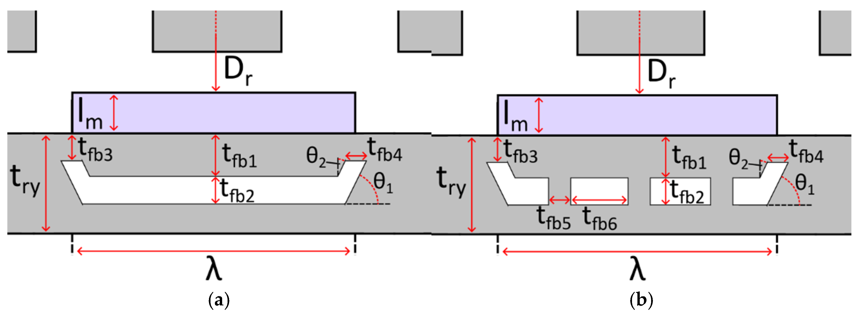
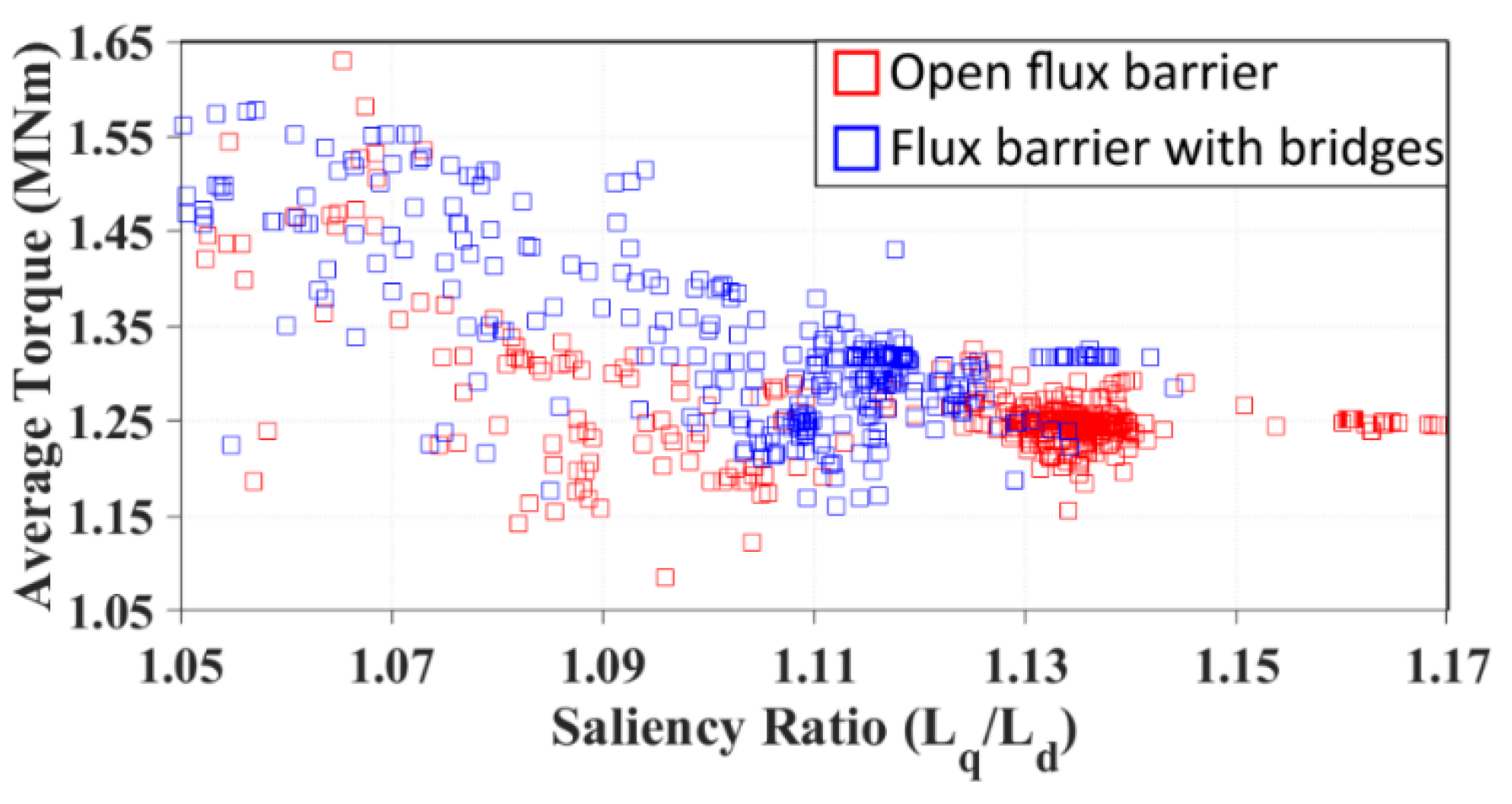
4.4. Rotor Flux Barriers

The primary contribution to torque capability in synchronous reluctance machines is reluctance torque. This reluctance torque results from a very anisotropic rotor structure that uses flux barriers in the rotor to adjust the d- and q-axis inductances accordingly. In this section, the inclusion of flux barriers behind the rotor PMs is briefly studied, to see if they can contribute to an increase in saliency ratio without reducing the torque capability of the FSCW machine. As this greatly adds to the complexity of the geometry, a multi-objective genetic algorithm optimization method was needed that could optimize for both saliency ratio and onload torque simultaneously. This was not possible in OPERA, and so two 3 MW FSCW machines with flux barriers were modelled in JMAG. One design was a simple flux barrier, like what would be found in a synchronous reluctance machine, and the other included flux bridges within the barrier. The two-flux barrier structures can be seen in Figure 29 with corresponding optimization parameters labelled. The optimization setup using these parameters is then given in Table 4. For the optimization, a limit of 100 generations and a population size of 200 were set. The fitness function, defined under “Objective Functions”, aims to maximize torque while maintaining a saliency ratio of 1.2.
The results of these two optimization studies can be seen in Figure 30, where the average onload torque of each design is plotted against its saliency ratio. It is found that neither design can achieve a saliency ratio of 1.2, or even approach 1.2, without an unacceptable reduction in onload torque capability. Thus, this investigation was not continued.

5. Design of 3 MW FSCW Machine with High Saliency Ratio

Section 3 and Section 4 present a wide-ranging series of investigations into methods for improving the saliency ratio of 3 MW FSCW machines. It was identified that without magnetic circuit alteration no real increase could be achieved. Of the magnetic circuit alteration methods, the most effective method for improving the saliency ratio with minimal impact on machine performance was the inclusion of rotor shoes between the PMs. For this section, this topology will be taken forward to try and obtain a salient 3 MW FSCW generator without reducing machine electromagnetic performance. To accomplish this, JMAG was once again used to model the machine and use the multi-objective optimization feature.

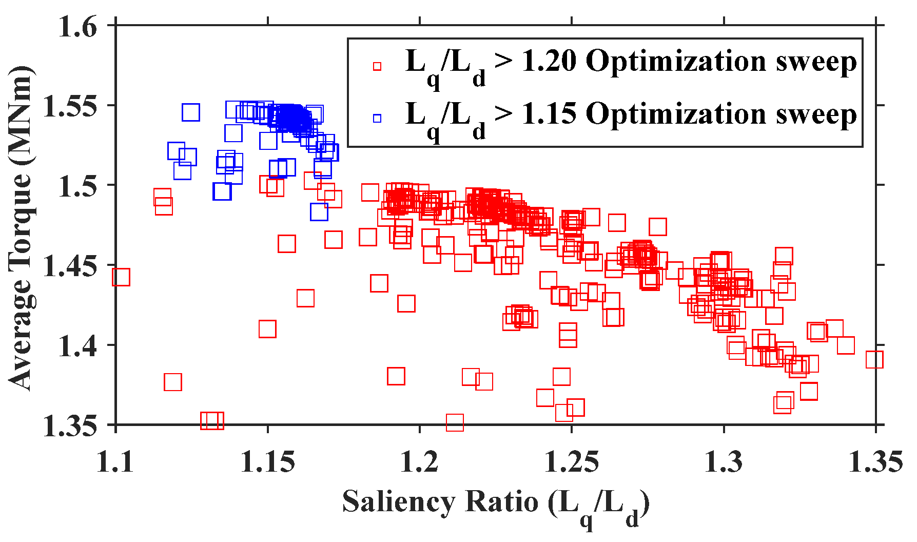
5.1. Optimization Process

JMAG’s optimization suite was used for a 192s/160p three-phase machine to try and maintain a high torque performance while simultaneously achieving a saliency ratio of 1.2. After this sweep, a few outlier designs demonstrated reasonable torque capability for a saliency ratio of 1.15. Thus, a second sweep was carried out with updated parameters close to these designs and a saliency ratio objective of 1.15. The optimization parameters for these sweeps can be seen in Table 5, and the results for both optimization studies can be seen in Figure 31.
There is a very clear drop in machine performance with increasing saliency ratios, and all machine designs that achieve a saliency ratio of 1.15 or 1.2 are not capable of reaching 1.55 MNm or 1.5 MNm of average torque, respectively. The two optimization studies yielded the following 3 MW machine geometries given in Table 6, with models displayed in Figure 32. These machines will then be compared in the following section.

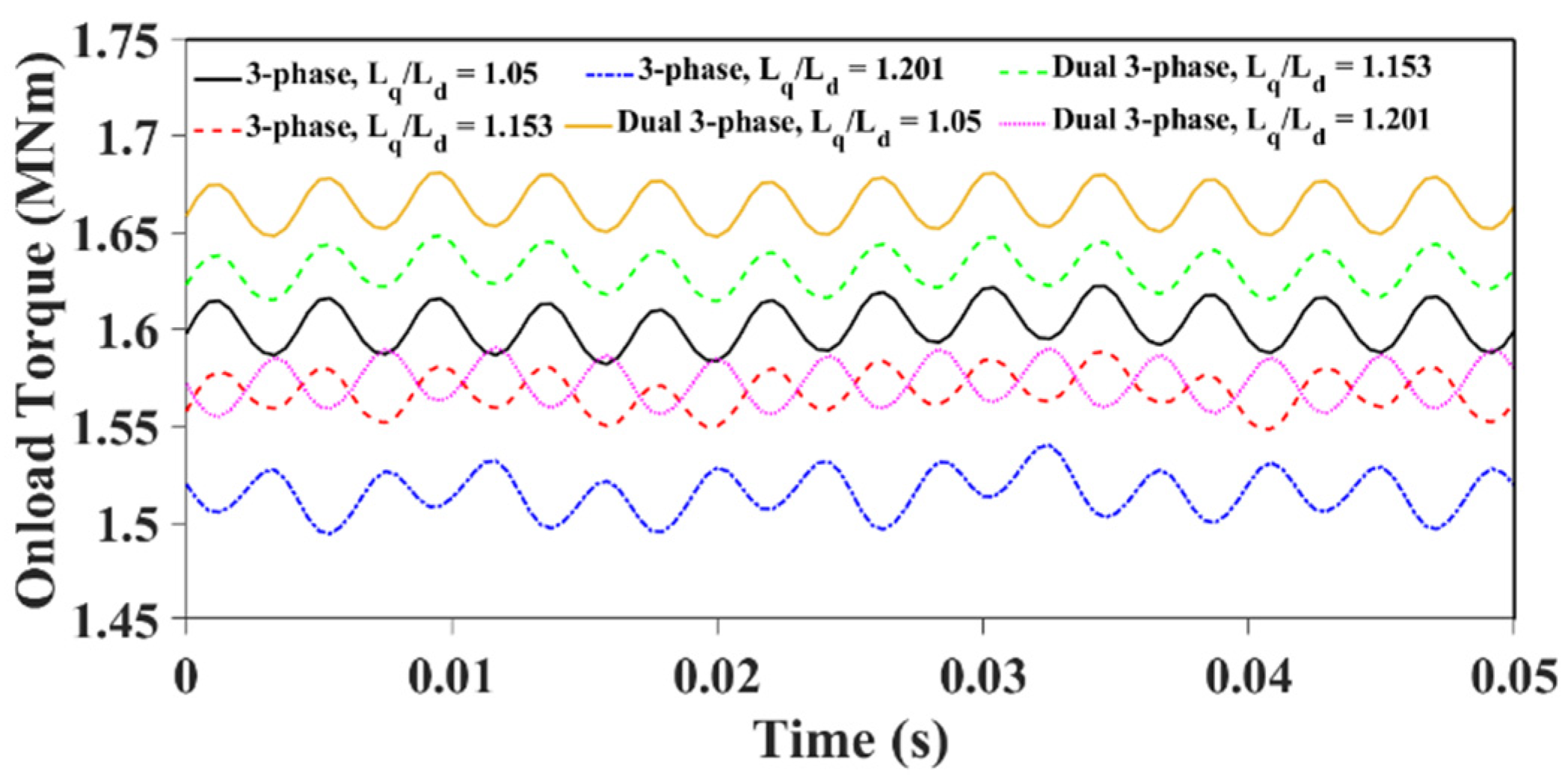
5.2. Machine Comparison

The three machines are first investigated under three-phase operation, as this was the winding configuration for which they were optimized. They are then compared under dual three-phase operation, with a 30 elec. deg. phase shift between the two converters. The comparison of torque performance can be seen in Figure 33, with a detailed breakdown in Table 7.
It can be seen that the achievable mechanical power of the 3 MW machine is diminished in order to achieve a higher saliency ratio. The conventional FSCW machine has a saliency ratio of 1.05 using the analytical stator steel data. In order to increase that saliency ratio to 1.15 or 1.2, the average torque of the dual three-phase machine is reduced by 1.8% and 5.4%, respectively. Given that this reduction is only to aid in the sensorless control capability of the machine, it is unlikely to serve as an attractive alternative to the conventional machine operating with sensors. In [15], several 3 MW generators were compared primarily by the stator power they were able to produce. This method is repeated here as it is a critical indicator for the effectiveness of a machine’s design for use in offshore wind power. The stator structure remained unchanged for all machines, and therefore the copper losses will remain the same, which is 46.3 kW in this study. The remaining losses were all calculated using JMAG and are given in Table 8 along with the efficiency and developed stator power of the machine topologies.
It can be seen that both the salient structures increase the rotor loss by 77% and 60% for the salient 1.15 and 1.2 dual three-phase machines, respectively. However, the salient 1.2 design leads to a 38% reduction in PM eddy current losses caused by the thick magnets with reduced pole arc. Crucially, both machine topologies fail to match the stator power developed by the original dual three-phase machine. The reduction in stator power is 3.40% and 6.16% for the salient 1.15 and 1.2 dual three-phase machines, respectively. This sacrifice in power is likely too great to outweigh the added cost of sensor failure on lifetime annual energy production [19], but it would require further investigation to absolutely conclude this. As it has been demonstrated in Section 4.2 that without eddy current losses a saliency ratio of 1.2 can be achieved with only a 0.5% reduction in torque performance, there could be merit in investigating the use of rotor shoes with a laminated rotor iron core. However, moving to such a structure would greatly increase cost and be detrimental to the mechanical strength of the rotor, so it is beyond the scope of this work.

6. Conclusions

This paper investigated the saliency of machines equipped with FSCWs for application in offshore wind turbine generators. Initially, a comparative study was carried out where a 480s/160p ISW machine was compared with a 192s/160p FSCW machine in terms of its d- and q-axis inductances and saliency ratio for a wide range of operating conditions. It was identified that the saliency ratio of the 3 MW machines investigated diminishes as the slots per pole per phase ratio (spp number) decreases. This is because the high saliency ratio present in the ISW machine structure is caused by main flux saturation, which reduces as the thickness of teeth increases relative to the same pole pitch. Following this study, an investigation into methods for improving the saliency ratio of the 192s/160p FSCW machine was carried out. The aim was to achieve a saliency ratio of 1.2 with minimal impact on torque performance, as this would reduce the effectiveness of this winding topology for use in offshore wind power. The investigation was split into two main sections:
(1)
The composition of the magnetic circuit was unaltered, i.e., conventional geometry was maintained.
(2)
The magnetic circuit was altered through the addition or removal of rotor/stator steel.
It was found that it was effectively impossible to achieve a saliency ratio of 1.2 without magnetic circuit alteration. The only time a saliency ratio of 1.2 was reached with conventional geometry required extremely high magnetic flux saturation such that the onload torque capability was substantially reduced. Of all the methods of magnetic circuit alteration, it was deemed that the addition of rotor shoes between the PMs was the most effective solution for increasing the saliency ratio while minimizing the reduction in machine torque capability. A 3 MW FSCW machine with rotor shoes for improved saliency was then optimized to try and achieve a high saliency ratio while maintaining high onload torque capability. Two machine designs were proposed, one that achieves a saliency ratio of 1.15 and one that achieves a saliency ratio of 1.2. Unfortunately, these machines reduced the torque capability of a conventional 192s/160p dual three-phase machine by 1.8% and 5.4%, respectively. This reduction in mechanical power, coupled with an increase in rotor eddy current losses, yielded a reduction in stator power of 3.40% and 6.16% for the salient 1.15 and 1.2 dual three-phase machines. This power decrease would lead to a corresponding reduction in annual energy production and therefore makes these machine structures an infeasible solution for improving the saliency ratio of FSCW machines for wind power application.
Unfortunately, this work has not achieved the desired aim; however, in Section 2.2, it is highlighted that an spp number of 0.8, corresponding to a 384s/160p machine, has a saliency ratio of approximately 1.2. In [15], this machine structure is combined with dual star–delta windings and achieves an increased stator power when compared with the ISW baseline machine. Since this structure has been shown to achieve a saliency ratio of nearly 1.2, it presents an even more attractive design choice for offshore wind power, as it enables sensorless control. This will be explored further in future work.

Author Contributions

Writing—original draft, I.R.; writing—review and editing, and supervision, G.-J.L. and Z.-Q.Z.; funding acquisition and supervision, A.D. and R.C. All authors have read and agreed to the published version of the manuscript.

Funding

This work is supported by the UK Engineering and Physical Science Research Council (EPSRC) Partnership, a new partnership in Offshore Wind under Grant EP/R004900/1.

Data Availability Statement

The original contributions presented in the study are included in the article; further inquiries can be directed to the corresponding author.

Conflicts of Interest

Authors Alexander Duke and Richard Clark were employed by the company Siemens Gamesa Renewable Energy Ltd. The remaining authors declare that the research was conducted in the absence of any commercial or financial relationships that could be construed as a potential conflict of interest.

Nomenclature

L d ,   L q d- and q-axis self-inductances
M d q ,   M q d d- and q-axis mutual inductances
i d ,   i q d- and q-axis currents
ψ d ,   ψ q d- and q-axis flux linkages
ψ p m PM flux linkages
sppSlots per pole per phase
lmMagnet thickness
lgAir-gap length
VmMagnet volume
βSlot–tooth ratio
DrRotor outer diameter
λMagnet arc
σConductivity

References

  1. Wu, R.; Slemon, G.R. A permanent magnet motor drive without a shaft sensor. IEEE Trans. Ind. Appl. 1991, 27, 1005–1011. [Google Scholar] [CrossRef]
  2. Chen, Z.; Tomita, M.; Doki, S.; Okuma, S. An extended electromotive force model for sensorless control of interior permanent-magnet synchronous motors. IEEE Trans. Ind. Electron. 2003, 50, 288–295. [Google Scholar] [CrossRef]
  3. Yang, S.-C.; Suzuki, T.; Lorenz, R.D.; Jahns, T.M. Surface-permanent-magnet synchronous machine design for saliency-tracking self-sensing position estimation at zero and low speeds. IEEE Trans. Ind. Appl. 2011, 47, 2103–2116. [Google Scholar] [CrossRef]
  4. Jang, J.-H.; Sul, S.-K.; Ha, J.-I.; Ide, K.; Sawamura, M. Sensorless drive of surface-mounted permanent-magnet motor by high-frequency signal injection based on magnetic saliency. IEEE Trans. Ind. Appl. 2003, 39, 1031–1039. [Google Scholar] [CrossRef]
  5. Wang, Y.; Zhu, J.; Wang, S.; Guo, Y.; Xu, W. Nonlinear magnetic model of surface mounted PM machines incorporating saturation saliency. IEEE Trans. Magn. 2009, 45, 4684–4687. [Google Scholar] [CrossRef]
  6. Tangudu, J.K.; Jahns, T.M.; El-Refaie, A. Unsaturated and saturated saliency trends in fractional-slot concentrated-winding interior permanent magnet machines. In Proceedings of the 2010 IEEE Energy Conversion Congress and Exposition (ECCE), Atlanta, GA, USA, 12–16 September 2010. [Google Scholar]
  7. Pouramin, A.; Dutta, R.; Rahman, M.F.; Xiao, D. Inductances of a fractional-slot concentrated-winding interior PM synchronous machine considering effects of saturation and cross magnetization. In Proceedings of the 2015 IEEE Energy Conversion Congress and Exposition (ECCE), Montreal, QC, Canada, 20–24 September 2015. [Google Scholar]
  8. Leidhold, R. Position sensorless control of PM synchronous motors based on zero-sequence carrier injection. IEEE Trans. Ind. Electron. 2011, 58, 5371–5379. [Google Scholar] [CrossRef]
  9. Yang, S.-C.; Lorenz, R.D. Surface permanent-magnet machine self-sensing at zero and low speeds using improved observer for position, velocity, and disturbance torque estimation. IEEE Trans. Ind. Appl. 2012, 48, 151–160. [Google Scholar] [CrossRef]
  10. Hoang Duy, T.; Phung Anh, T. Surface-mounted permanent magnet synchronous motor design ready for sensorless control at zero and low speed. In Proceedings of the 2022 11th International Conference on Control, Automation and Information Sciences (ICCAIS), Hanoi, Vietnam, 21–24 November 2022. [Google Scholar]
  11. Bianchi, N.; Bolognani, S.; Jang, J.-H.; Sul, S.-K. Advantages of inset PM machines for zero-speed sensorless position detection. IEEE Trans. Ind. Appl. 2008, 44, 1190–1198. [Google Scholar] [CrossRef]
  12. Bianchi, N.; Bolognani, S.; Faggion, A.; Fornasiero, E. Analysis and experimental tests of the sensorless capability of a fractional-slot inset PM motor. IEEE Trans. Ind. Appl. 2015, 51, 224–231. [Google Scholar] [CrossRef]
  13. Zhang, Z.; Xia, C.; Wang, H.; Shi, T. Analytical field calculation and analysis of surface inset permanent magnet machines with high saliency ratio. IEEE Trans. Magn. 2016, 52, 8108612. [Google Scholar] [CrossRef]
  14. Krizan, J.A.; Sudhoff, S.D. A design model for salient permanent-magnet machines with investigation of saliency and wide-speed-range performance. IEEE Trans. Energy Convers. 2013, 28, 95–105. [Google Scholar] [CrossRef]
  15. Rudden, I.; Li, G.-J.; Zhu, Z.-Q.; Duke, A.; Clark, R. Analysis of MW-level offshore wind turbine generators with dual star–delta fractional-slot windings. Energies 2024, 17, 2958. [Google Scholar] [CrossRef]
  16. Rudden, I.; Wang, P.; Li, H.; Li, G.J.; Zhu, Z.Q.; Duke, A.; Clark, R. DQ analysis of fractional-slot machines with star-delta concentrated winding. IEEE Access 2024, 12, 84680–84690. [Google Scholar] [CrossRef]
  17. Li, G.J.; Zhu, Z.Q.; Chu, W.Q.; Foster, M.P.; Stone, D.A. Influence of flux gaps on electromagnetic performance of novel modular PM machines. IEEE Trans. Energy Convers. 2014, 29, 716–726. [Google Scholar] [CrossRef]
  18. Yao, Y.; Lu, Q. Comparative study of E-Core and C-Core modular PM linear machines with different slot/pole combinations. IEEE Trans. Magn. 2017, 53, 8110307. [Google Scholar] [CrossRef]
  19. Kang, J.; Sun, L.; Guedes Soares, C. Fault tree analysis of floating offshore wind turbines. Renew. Energy 2019, 133, 1455–1467. [Google Scholar] [CrossRef]
Figure 1. Machine winding layouts: (a) 480s/160p and (b) 192s/160p. Note that for the 480s/160p machine a full winding periodicity is displayed, and for the 192s/160p only half the winding periodicity is displayed.
Energies 18 02057 g001
Figure 2. Apparent inductances of 480s/160p machine. (a) Ld, (b) Lq, (c) Mdq, and (d) Mqd.
Energies 18 02057 g002
Figure 3. Apparent inductances of 192s/160p machine. (a) Ld, (b) Lq, (c) Mdq, and (d) Mqd.
Energies 18 02057 g003
Figure 4. Incremental inductances of 480s/160p machine. (a) Ld, (b) Lq, (c) Mdq, and (d) Mqd.
Energies 18 02057 g004
Figure 5. Incremental inductances of 192s/160p machine. (a) Ld, (b) Lq, (c) Mdq, and (d) Mqd.
Energies 18 02057 g005
Figure 6. Saliency ratios of investigated machines: 480s/160p (a) apparent and (b) incremental inductances; 192s/160p (c) apparent and (d) incremental inductances.
Energies 18 02057 g006
Figure 7. Saliency ratio using incremental inductances under three d-axis currents of 480s/160p and 192s/160p machines. id1 = −420 A, id2 = 20 A, and id3 = 420 A.
Energies 18 02057 g007
Figure 8. Modified apparent inductances used in saliency ratio calculation.
Energies 18 02057 g008
Figure 9. Saliency ratio for different spp number machines across q-axis currents. (a) Apparent inductances used and (b) incremental inductances used.
Energies 18 02057 g009
Figure 10. Saliency ratio and mean tooth flux density versus spp ratio.
Energies 18 02057 g010
Figure 11. Flux saturation within the teeth of different-spp-number 3 MW machines: (a) 192s/160p (spp = 0.4), (b) 384s/160p (spp = 0.8), (c) 480s/160p (spp = 1.0), and (d) 960s/160p (spp = 2.0).
Energies 18 02057 g011
Figure 12. Conventional geometry investigation flowchart. In this figure, lm and lg are the magnet thickness and air-gap length, and Vm is the magnet volume.
Energies 18 02057 g012
Figure 13. Alternative windings of 192s/160p 3-phase machine. (a) Single-layer windings, (b) star–delta double-layer windings, and (c) star–delta winding connection.
Energies 18 02057 g013
Figure 14. Impact of different winding structures on saliency ratios.
Energies 18 02057 g014
Figure 15. Impact of slot–tooth ratio (β) on saliency ratio.
Energies 18 02057 g015
Figure 16. Saliency ratio and onload torque with varying yoke thickness.
Energies 18 02057 g016
Figure 17. Dimensions for magnet and air-gap. In this figure, Dr is the rotor inner diameter and λ is the magnet arc.
Energies 18 02057 g017
Figure 18. Magnet and air-gap dimension impact on saliency ratio. (a) Saliency ratio versus magnet pole arc and (b) saliency ratio versus air-gap length.
Energies 18 02057 g018
Figure 19. Magnetic circuit alteration investigation flowchart. ISPM is inset permanent magnet rotor.
Energies 18 02057 g019
Figure 20. Machine structure including tooth tips.
Energies 18 02057 g020
Figure 21. Flux density plots of different stator teeth. (a) Thick tooth tips and (b) thin tooth tips.
Energies 18 02057 g021
Figure 22. Impact of tooth tips on saliency ratio.
Energies 18 02057 g022
Figure 23. Machine with and without rotor shoes. (a) Conventional SPM and (b) SPM with rotor shoes.
Energies 18 02057 g023
Figure 24. Impact of rotor shoe height on saliency ratio and onload torque.
Energies 18 02057 g024
Figure 25. Impact of conductivity on machine performance.
Energies 18 02057 g025
Figure 26. Flux gap topologies under investigation. (a) Flux gaps in every tooth and (b) flux gaps in alternate teeth.
Energies 18 02057 g026
Figure 27. Impact of stator flux gaps in every tooth on saliency ratio. (a) Constant copper area and (b) constant tooth area.
Energies 18 02057 g027
Figure 28. Impact of stator flux gaps in alternate teeth on saliency ratio. (a) Constant tooth area and (b) constant copper area.
Energies 18 02057 g028
Figure 29. Flux barrier designs and parameters for optimization. (a) Open flux barrier—Study 1, and (b) flux barrier with bridges—Study 2.
Energies 18 02057 g029
Figure 30. Saliency ratio optimization for FSCW machines with rotor flux barriers.
Energies 18 02057 g030
Figure 31. The results of the two optimization investigations.
Energies 18 02057 g031
Figure 32. Salient machine topologies. (a) Lq/Ld = 1.15 and (b) Lq/Ld = 1.20.
Energies 18 02057 g032
Figure 33. Onload torque performance comparison of salient FSCW machine designs.
Energies 18 02057 g033
Table 1. The 3 MW ISW parameters [15].
Slot number480Winding layers1
Pole number160Slot width to tooth width ratio (β)5/11
Rotor inner radius (m)2.5Rated speed (RPM)15
Air-gap length (mm)5Number of turns per coil12
Magnet length (mm)15Number of parallel strings20
Slot height (mm)80Rated current (Arms)160
Yoke height (mm)40Magnet–span ratio0.8
Stack length (m)1.2Magnet remanence (T)1.237
Table 2. Slot number and corresponding spp of investigated machines.
Slot NumberSlots per Pole per Phase (spp)Conductors per SlotCoil Pitch
1440.3401
1920.4301
2400.5242
3840.8152
4801.0123
5761.2104
7201.584
8641.86.665
9602.066
14403.049
19204.0312
Table 3. Torque performance comparison of machines with and without rotor shoes and iron conductivity (σ).
σAverage Torque (MNm)Torque Ripple (kNm)Torque Ripple (%)
No Pole ShoesNo1.70233.36980.0198
No Pole ShoesYes1.6233.9870.0246
15 mm Pole ShoesNo1.6942 (−0.48%)3.0880 (−8.36%)0.0182
15 mm Pole ShoesYes1.535 (−5.42%)7.003 (+75.65%)0.0456
Table 4. Optimization setup for flux barriers.
Optimization Study 1Optimization Study 2
Objective FunctionsMaximize average torqueMaximize average torque
Saliency ratio ≥ 1.2Saliency ratio ≥ 1.2
ConstraintsMachine outer radius ≤ 2555 mmMachine outer radius ≤ 2555 mm
Magnet area ≤ 1181.63 mm2Magnet area ≤ 1181.63 mm2
Model Parameters105 < phase angle (°) < 120105 < phase angle (°) < 120
4900 < Dr (mm) < 51004900 < Dr (mm) < 5100
10 < lm (mm) < 2010 < lm (mm) < 20
0.6 < λ < 0.90.6 < λ < 0.9
20 < try (mm) < 6020 < try (mm) < 60
2 < tfb1 (mm) < 202 < tfb1 (mm) < 20
2 < tfb2 (mm) < 102 < tfb2 (mm) < 10
2 < tfb3 (mm) < 152 < tfb3 (mm) < 15
2 < tfb4 (mm) < 152 < tfb4 (mm) < 15
10 < θ1 (°) < 455 < tfb5 (mm) < 20
0.05 < θ2 (°) < 0.55 < tfb6 (mm) < 20
10 < θ1 (°) < 45
0.05 < θ2 (°) < 0.5
Table 5. Optimization setup for rotor shoes.
Optimization Study 1Optimization Study 2
Objective FunctionsMaximize average torqueMaximize average torque
Saliency ratio ≥ 1.2Saliency ratio ≥ 1.15
ConstraintsMachine outer radius ≤ 2555 mmMachine outer radius ≤ 2555 mm
Magnet area ≤ 1181.63 mm2Magnet area ≤ 1181.63 mm2
Model Parameters105 < phase angle (°) < 120100 < phase angle (°) < 110
10 < magnet height (mm) < 2014 < magnet height (mm) < 16
0.6 < magnet pitch < 0.90.75 < magnet pitch < 0.85
0 < shoe height (mm) < 208 < shoe height (mm) < 12
0.1 < shoe pitch < 0.40.13 < shoe pitch < 0.17
2440 < rotor inner radius (mm) < 25402490 < rotor inner radius (mm) < 2510
20 < rotor yoke thickness (mm) < 6035 < rotor yoke thickness (mm) < 45
Table 6. MW salient machine parameters.
Conventional L q / L d > 1.15 L q / L d > 1.2
Air-gap radius (mm)25002496.52511.7
Rotor yoke thickness (mm)4039.223.9
Magnet height (mm)1515.118.5
Magnet pitch0.80.7940.644
Rotor shoe height (mm)n/a10.115.9
Rotor shoe pitchn/a0.1560.105
Table 7. Torque performance comparison.
Average Torque
(MNm)
Torque Ripple
(KNm)
Torque Ripple
(%)
Mech Power
(MW)
Conventional three-phase1.6040.42.522.51
Salient (1.15) three-phase1.5740.22.572.47
Salient (1.2) three-phase1.5245.83.022.39
Conventional dual three-phase1.6633.21.992.61
Salient (1.15) dual three-phase1.6333.82.082.56
Salient (1.2) dual three-phase1.5735.92.282.47
Table 8. Losses and efficiency comparison.
Stator Loss
(kW)
Rotor Loss (kW)PM Loss (kW)Efficiency (%)Stator Power (MW)
Conventional three-phase17.657.143.293.482.35
Salient (1.15) three-phase18.192.643.691.852.26
Salient (1.2) three-phase15.874.826.793.132.22
Conventional dual three-phase17.843.544.394.192.46
Salient (1.15) dual three-phase17.477.142.392.852.38
Salient (1.2) dual three-phase16.369.727.593.532.31
Disclaimer/Publisher’s Note: The statements, opinions and data contained in all publications are solely those of the individual author(s) and contributor(s) and not of MDPI and/or the editor(s). MDPI and/or the editor(s) disclaim responsibility for any injury to people or property resulting from any ideas, methods, instructions or products referred to in the content.

