Article

Optimal and Sustainable Operation of Energy Communities Organized in Interconnected Microgrids

by
Epameinondas K. Koumaniotis
,
Dimitra G. Kyriakou
and
Fotios D. Kanellos
*
School of Electrical and Computer Engineering, Technical University of Crete, GR-73100 Chania, Greece
*
Author to whom correspondence should be addressed.
Energies 2025, 18(8), 2087; https://doi.org/10.3390/en18082087
Submission received: 1 April 2025 / Revised: 13 April 2025 / Accepted: 16 April 2025 / Published: 18 April 2025
(This article belongs to the Special Issue Advances in Sustainable Power and Energy Systems)

Abstract

:
Full dependence on the main electrical grid carries risks, including high electricity costs and increased power losses due to the distance between power plants and consumers. An energy community consists of distributed generation resources and consumers within a localized area, aiming to produce electricity economically and sustainably while minimizing long-distance power transfers and promoting renewable energy integration. In this paper, a method for the optimal and sustainable operation of energy communities organized in interconnected microgrids is developed. The microgrids examined in this work consist of residential buildings, plug-in electric vehicles (PEVs), renewable energy sources (RESs), and local generators. The primary objective of this study is to minimize the operational costs of the energy community resulting from the electricity exchange with the main grid and the power production of local generators. To achieve this, microgrids efficiently share electric power, regulate local generator production, and leverage energy storage in PEVs for power management, reducing the need for traditional energy storage installation. Additionally, this work aims to achieve net-zero energy exchange with the main grid, reduce greenhouse gas (GHG) emissions, and decrease power losses in the distribution lines connecting microgrids, while adhering to numerous technical and operational constraints. Detailed simulations were conducted to prove the effectiveness of the proposed approach.

1. Introduction

The concept of energy communities has emerged in response to the increasing decentralization of the electric power system and the integration of renewable energy sources. An energy community primarily meets its energy demand through local renewable power generation, supplemented by conventional power sources. Its objective is to optimize local energy production, storage, and consumption to minimize reliance on the main grid.
A comprehensive review of the literature and state-of-the-art advancements has been conducted to identify research opportunities and potential technological enhancements in the field. In [1], a two-stage risk-based optimization model is developed for energy management systems (EMSs) within citizen and renewable energy communities to maximize profit. In the first stage, each energy community manager optimizes the profit of their respective community, while in the second stage, the network operator maximizes the overall network profit. The inherent complexity in modeling such energy communities presents significant challenges in formulating and solving the associated optimization problems. To address this challenge, ref. [2] proposes a mixed-integer linear programming (MILP)-based optimal planning approach for renewable energy communities, incorporating time-of-use electricity rates specific to each node. The results demonstrate that increasing the share of photovoltaic energy within the community, coupled with energy exchange among members and the integration of a battery energy storage system, reduces operational costs and emissions. Additionally, the energy storage system facilitates peak load shaving, thereby lowering peak-load-related costs. In [3], a linear programming-based study that optimizes the size of photovoltaic systems and battery storage in renewable energy communities is presented. The study evaluates the effects of varying battery installation locations, peak load shaving, and different battery operation strategies on system performance. In [4], the local energy generation within an energy community reduces costs for all participants. Additionally, the EMS proposed in [5] successfully lowers the annual peak load of the community’s low-voltage substations with minimal impact on operational costs. A comprehensive review of energy communities is presented in [6], focusing on key stakeholders, power generation and information exchange technologies, individual and collective objectives, and community design types, as well as associated challenges, goals, trade-offs, and socio-economic impacts.
A well-structured energy community can be conceptualized as a network of interconnected microgrids within a defined geographical area. Microgrids have been extensively studied so far. In [7], a switched hybrid model predictive control optimization is proposed, employing a three-stage testing process to minimize the total energy purchase cost of a microgrid in both grid-connected and islanded operation. By integrating battery energy storage (BES) and RESs, the microgrid can effectively respond to sudden changes in power grid conditions. Demand-side management techniques, regulatory frameworks, and technical capabilities within a microgrid are examined in [8]. The optimization process consists of two stages: the first optimally schedules heating, ventilation, and air conditioning (HVAC), lighting, and EV loads, while the second minimizes total investment and operational costs. In [9], the microgrid operation in both grid-connected and islanded modes of operation using a two-layer coordination control system is simulated, ensuring a high load satisfaction rate. A rule-based modular energy management system that enables the dynamic utilization of all components in both isolated and grid-connected hybrid DC/AC microgrids is presented in [10]. The uncertainties of wind, solar irradiation, and electric loads are addressed in [11] through a flexible two-stage robust optimization problem, which minimizes investment, maintenance, and operational costs while maximizing the microgrid’s profits. Simulation results in [12] highlight the benefits of integrating electric vehicles within a microgrid, reducing power demand fluctuations by adjusting their power injection. Additionally, BES enables interruptible loads to provide ancillary services to the main grid. Researchers in [13] develop a microgrid controller that stabilizes grid voltage by solving the optimal power flow problem, formulated as a quadratically constrained quadratic program (QCQP) optimization problem and solved using the interior point method. The authors of [14] explore the optimal reactive power dispatch of power converters, enabling the injection of reactive power from DERs outside the microgrid to assist the main grid with its reactive power balance. Prosumers are tasked with deciding whether to provide power services or prioritize other actions for cost minimization. An in-depth review of microgrids is presented in [15].
The integration of multiple microgrids has also been explored in research. In [16], a two-layer optimization model is presented for the cooperation between multiple microgrids and a county-based system operator, discussing four typical microgrid scenarios. A trading mechanism between the rural multi-microgrid and the county-oriented energy operator is developed. This approach reduces both the multi-microgrid’s operational costs and the operator’s costs, decreases reliance on the main grid, and increases renewable energy consumption. The cooperation between multi-microgrids and active distribution networks is demonstrated in [17], where the introduced method reduces operational costs and carbon emissions for both parties. Additionally, it successfully achieves a fair distribution of carbon emissions between the active distribution network and the multi-microgrid. The optimal operation of interconnected microgrids participating in a peer-to-peer (P2P) electricity market is thoroughly analyzed in [18]. Initially, each microgrid minimizes its operational costs while meeting its building’s electrical and thermal needs and optimizing EV operation. Subsequently, each microgrid participates in the P2P market to gain profit by supporting one another’s stability and aligning with their individual interests. The minimum and maximum allowed power deviations for each microgrid are calculated to maximize its influence on the electricity market. Researchers in [19] examine a cluster of interconnected microgrids in off-grid communities, developing a model to prevent simultaneous bidirectional power transfer between microgrids while accounting for transmission distances. Additionally, demand-response strategies are employed to further reduce diesel generator fuel consumption. The design process of a multi-microgrid system is presented in [20], considering both installation and operational costs, formulated as a two-stage stochastic programming model. In [21], an innovative load shifting method in microgrid-based energy community is presented. By effectively managing HVAC power consumption and auxiliary generator operation, a significant portion of the electrical load can be shifted to achieve valley-filling and peak-shaving, while adhering to the thermal and electrical constraints of the community for both heating and cooling operation scenarios. In [22], clusters of residential microgrids within a renewable energy community are optimally organized to provide grid balancing services. In [23], it is highlighted that interconnecting multiple microgrids into a microgrid cluster is an effective method to enhance the operational quality of distributed generation. A multi-stage EMS designed to reduce load shedding and load losses by providing accurate forecasts of these issues is introduced in [24]. A survey on the operation of interconnected microgrids, available topologies, and energy management methods is provided in [25].
Based on the conducted literature review, the innovative aspects of this study are highlighted as follows:
-
The proposed algorithm ensures a reduction in the energy community’s daily operational costs by enabling efficient power sharing between the interconnected microgrids, regulating local generators’ output, and utilizing PEVs for power management, thereby minimizing the need for additional energy storage systems. This integrated approach better aligns with the needs of energy communities organized in interconnected microgrids, as it effectively deals with the complexities of distributed energy resources and diverse load profiles, ensuring efficient energy management across multiple interacting microgrids.
-
Achieving net-zero energy exchange between the energy community and the main grid is crucial for enhancing energy independence and improving overall system resilience. By balancing local generation and consumption, this approach optimizes resource utilization within the energy community while decreasing reliance on external power sources.
-
Reducing power losses in the distribution lines connecting the microgrids is crucial for improving the overall efficiency of energy distribution within interconnected systems. By minimizing these losses, more of the locally generated electricity is effectively utilized, which enhances system reliability and reduces operational costs. This optimization of power flow also contributes to a more sustainable energy network by ensuring that less energy is wasted in energy distribution, making the entire system more efficient and resilient.
-
Reducing greenhouse gas (GHG) emissions from local generators by setting appropriate constraints is essential for promoting environmental sustainability and aligning with global climate goals. By optimizing generator operations and limiting GHG emissions, this approach minimizes the carbon footprint of energy production while ensuring the seamless use of reliable, locally sourced power.
-
The proposed method is designed to be adaptable and scalable, making it applicable across different regions with varying characteristics, including areas with limited solar potential or high energy consumption. The optimization framework does not depend solely on high renewable energy generation but rather focuses on the coordinated management of all locally available resources—RESs, local generators, and PEVs—to achieve economic and environmental benefits.
-
The microgrids examined in our framework take advantage of a large number of PEVs, which provide a dynamic, dispersed, and flexible storage solution. PEVs can adjust their active power in real time, based on price signals and local demand fluctuations, enabling them to act as distributed energy storage units that respond to internal MG needs, optimizing both energy storage and overall microgrid operation. Compared to traditional storage systems, using PEVs provides economic benefits, as it minimizes additional infrastructure costs.
The rest of the article is structured as follows. Section 2 gives a detailed description of the proposed system. Section 3 outlines the energy community’s components modeling and in Section 4, the optimization of the energy community’s operation is described. Finally, Section 5 presents and analyzes the results obtained from the simulation of the examined system, while Section 6 provides the overall conclusions.

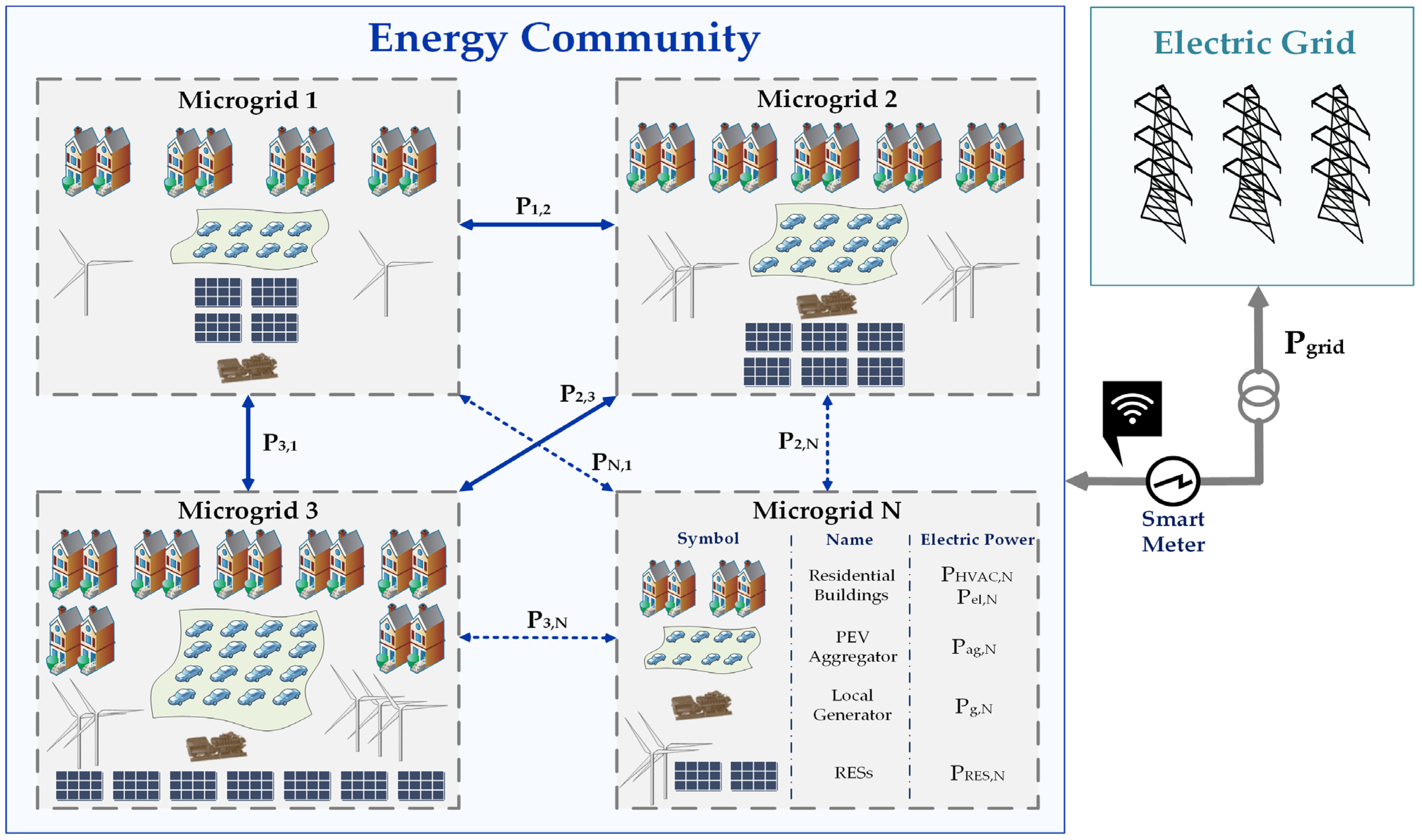
2. Proposed System Overall Description

The configuration of the proposed system is given in Figure 1. The examined energy community is organized in interconnected microgrids, allowing for efficient power exchange and resource sharing. Microgrids consist of residential buildings, PEVs, RESs, and local electrical generators. The loads within the examined energy community can be supplied from its power sources and the main electric grid.
The thermal and electrical loads of the residential buildings are modeled in detail according to building technical specifications, occupancy, activity level, various types of used appliances, the conditioned space of each building, ambient temperature, solar radiation, etc. An aggregation method is implemented to the hosted PEVs of each microgrid. The necessary PEV data, like the upper and lower bounds of their stored energy and power, are obtained by processed or real-world data [26]. The aggregator-based structure supports scalability and flexibility, allowing for the integration of stochastic user behavior models or learning-based forecasting in future extensions. This ensures that as PEV adoption grows and operational patterns diversify, the system can continue to deliver economically and environmentally optimal performance. In this study, PEVs not only draw power from the electric grid to charge their battery packs but also comprise Vehicle-to-Grid (V2G) operation mode, injecting power to the grid during specific time periods. Moreover, detailed models for microgrid local power generation units and RESs are developed.
The main goal of this method is to minimize the energy community’s daily operational costs, associated with electricity exchanged with the main electric grid and local generators production, on the assumption of operation under variable electricity prices. To achieve this, a hierarchical two-level optimization approach is applied. The primary objective of the first optimization level is to determine the optimal operation schedule for each microgrid’s PEV aggregator, while ensuring compliance with all PEV operation-associated constraints. Afterwards, the building HVAC and electrical loads of the energy community and total RES production, along with the optimal active power of each PEV aggregator that is determined in the first optimization level, are forwarded to the second optimization level. The main goal of the second optimization level is to minimize the energy community’s daily operational costs by optimally scheduling the operation of local power generator units. Simultaneously, the second optimization stage aims to achieve net-zero energy exchange between the energy community and the main grid, minimize power losses in transmission lines connecting microgrids, and reduce GHG emissions from local generators, thereby enhancing environmental sustainability. Additionally, the capacity constraints of distribution lines and the operational and technical limitations of local generators must be strictly attained. It is noted that in case of unexpected demand surges or an excess of RES production that cannot be handled in the fully constrained version of the examined problem, the net-zero energy constraint can be relaxed and, as a last resort, RES power production can be curtailed.
In this case study, the energy community consists of three physically interconnected microgrids. The interconnection between the energy community and the main power grid is realized through Microgrid 1, which functions as the point of common coupling (PCC) for the entire system. All active power exchange—either imported from or exported to the main grid—is managed solely through Microgrid 1. From a technical perspective, the power flow between the main grid and the rest of the energy community is facilitated via the internal distribution lines connecting the microgrids. This configuration is adopted for several technical, economic, and operational reasons: (1) Simplification of infrastructure requirements: Connecting only one microgrid to the main grid significantly reduces the complexity and cost of grid infrastructure. Each additional PCC would require dedicated protection, metering, control systems, and coordination mechanisms, thereby increasing system design and operational overhead. (2) Centralized grid interaction and control: A single grid connection point enables the centralized and more efficient management of energy exchange with the external grid. This simplifies energy accounting, grid service coordination, and communication with the system operator. (3) Improved optimization and load balancing: With a single PCC, the optimization framework can effectively manage energy distribution among microgrids. The second optimization level considers the power flow from the main grid into Microgrid 1 and then through the connecting lines to other microgrids, while minimizing transmission losses and operational costs and ensuring that all constraints are met. It is noted that although the above reasons advocate for a single PCC, the proposed method is developed in a way that allows multiple PCCs.

3. Energy Community Component Modeling

3.1. Building Thermal and Electrical Load Modeling

The necessary fundamental equations to construct the thermal model for each building are provided next (Equations (1)–(5)), while a comprehensive analysis of the thermal model can be found in [27].
ρ · C · V b · d T b d t = Q ˙ e x , w a l l , b + Q ˙ w i n , b + Q ˙ i n , b + Q ˙ s w , b + Q ˙ s g , b P H V A C , b · C O P
Q ˙ e x , w a l l , b = y E U w a l l , y · F w a l l , y · T o u t T b
Q ˙ w i n , b = y E U w i n , y · F w i n , y · T o u t T b
Q ˙ s w , b = y E a w · R s e · U w a l l , y · F w a l l , y · I T , b
Q ˙ s g , b = y E τ w i n , b · S C · F w i n , y · I T , b
where the b index denotes the building’s number; the y index denotes the yth external wall/window; C is the specific heat capacity; ρ denotes the air density; P H V A C , b denotes the HVAC electric power consumption of the bth building; Q ˙ e x , w a l l , b denotes the external walls’ heat exchange of the bth building; Q ˙ i n , b denotes the internal heat gains of the bth building; Q ˙ s g , b denotes the solar radiation through the windows of the bth building; Q ˙ s w , b denotes the heat gain by the external walls’ solar radiation of the bth building; Q ˙ w i n , b denotes the heat transfer across the windows of the bth building; T b denotes the bth building’s internal temperature (°C); T o u t denotes outdoor temperature (°C); V b is the volume of the bth building; C O P denotes the HVAC performance coefficient; a w denotes the absorbance coefficient of the external surface of the wall; F w a l l / F w i n denote the area of the total wall/window surface; I T , b denotes the total solar radiation of the bth building; R s e denotes the external surface heat resistance for the convection and radiation of the external wall; S C denotes the shading coefficient of the windows; τ w i n denotes the glass transmission coefficient of the windows; U w a l l / U w i n denote heat transfer coefficient of the external wall/window of the buildings; and E denotes the set of external walls.
The number and distribution of permanent occupants within a household, along with their activity levels, are key factors influencing the household’s electrical demand and internal thermal gain profiles. These characteristics, including the house’s geometry and occupant count, determine the specific functions assigned to individual rooms, which vary across different households based on their unique features and resident numbers. Additional information on building electrical load modeling is provided in [21].

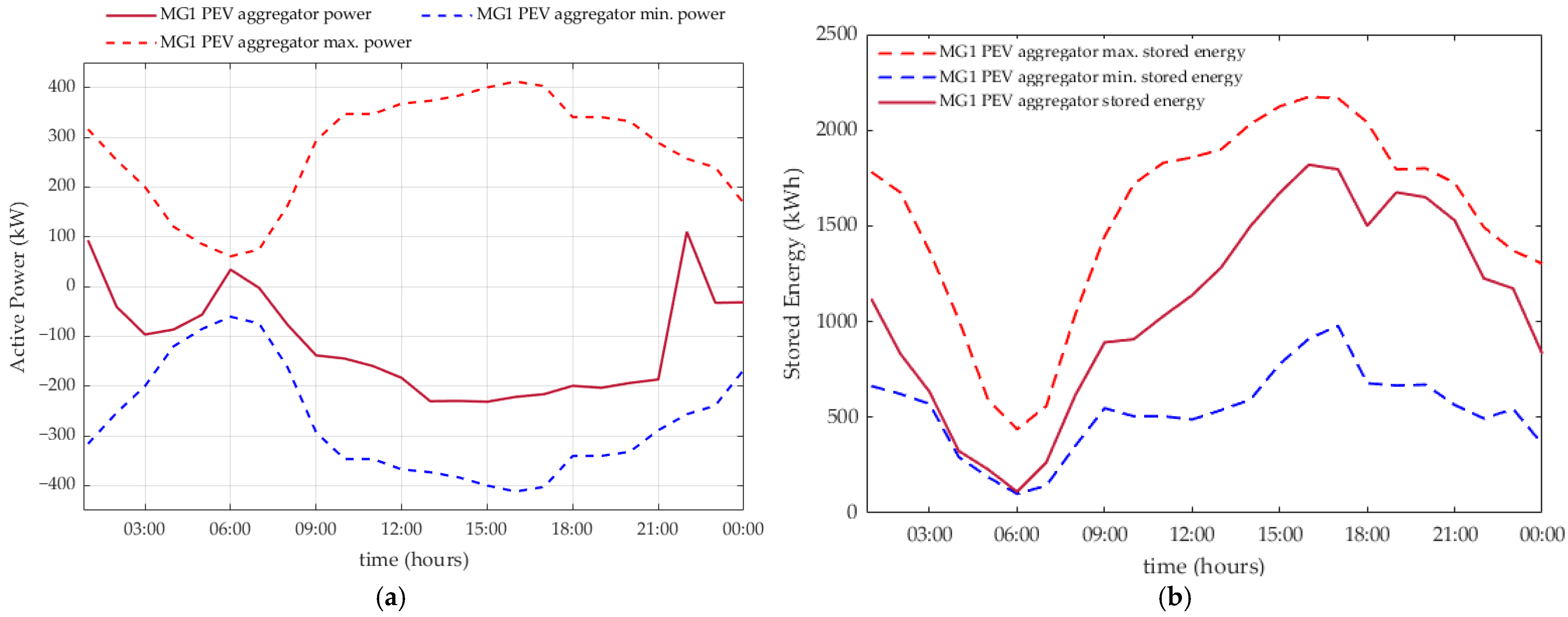
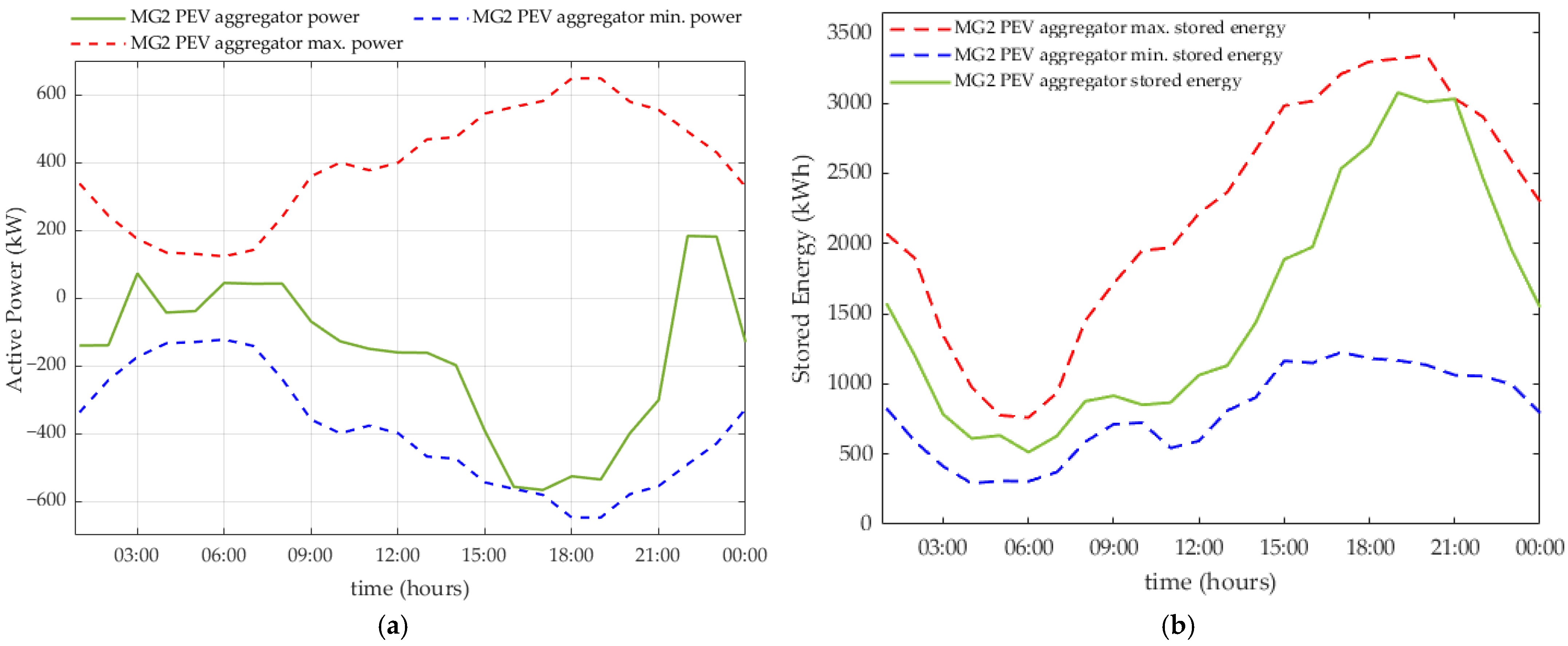
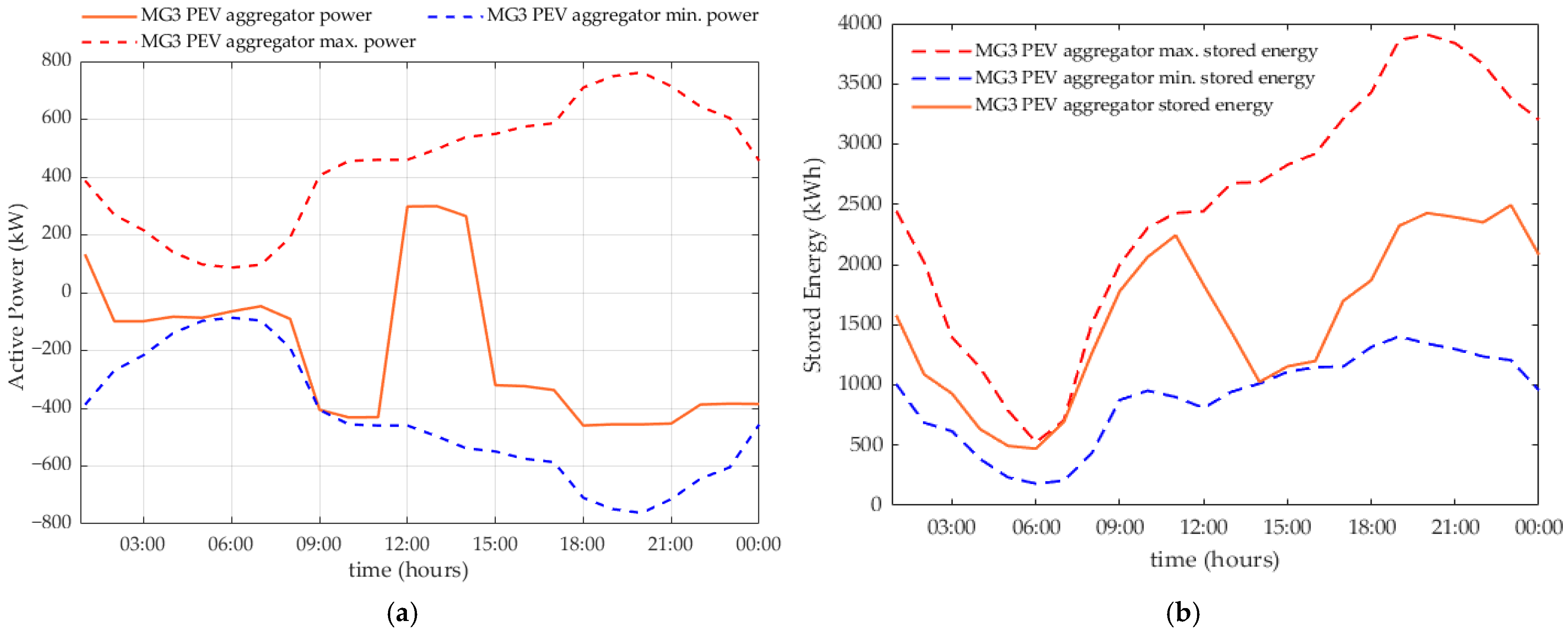
3.2. PEV Aggregator Modeling

Τhe PEVs hosted in each microgrid of the energy community are aggregated to obtain the time-varying limits of an equivalent battery using Equations (6)–(9).
P a g , m a x , m g t =   i t h   E V   p l u g g e d   a t   t P m a x , i , m g
P a g , m i n , m g t =   i t h   E V   p l u g g e d   a t   t P m i n , i , m g
S o C a g , m a x , m g t =   i t h   E V   p l u g g e d   a t   t S o C m a x , i , m g t S o C d , m g t
S o C a g , m i n , m g t =   i t h   E V   p l u g g e d   a t   t S o C m i n , i , m g t S o C d , m g t
where P a g , m a x , m g / P a g , m i n , m g denote the maximum/minimum active power of PEVs’ aggregate battery (kW) of the mgth microgrid; S o C a g , m a x , m g / S o C a g , m i n , m g is the maximum/minimum energy stored in the aggregate battery (kWh); P m a x , i , m g / P m i n , i , m g is the maximum/minimum charging active power of the ith PEV of the mgth microgrid; and S o C m a x , i , m g / S o C m i n , i , m g is the maximum/minimum energy stored in the ith PEV of the mgth microgrid, respectively, as defined in [28].
The energy stored in the aggregate battery dynamically changes due to the continuous plugging and unplugging of EVs in the mgth microgrid. It is denoted by S o C d , m g and it is calculated using Equation (10).
S o C d , m g t = T 0 : Δ t : t   ( S o C , a g , m g t S o C , a g , m g t )
S o C , a g , m g t =   i t h   E V   p l u g g e d   a t   t S o C 0 , i , m g
S o C , a g , m g t =   i t h   E V   u n p l u g g e d   a t   t S o C t , i , m g
where S o C 0 , i , m g denotes the energy stored in the ith PEV of the mgth microgrid at its connection time and S o C t , i , m g is the energy stored in the ith PEV of the mgth microgrid at its disconnection time.
Assuming that P a g , m g ( t ) is the optimal active power of the aggregate battery of the mgth microgrid and adopting the generator convention, the energy stored in the aggregate battery, S o C a g , m g (kWh), is given by Equation (13).
S o C a g t + Δ t = S o C a g , m g t P a g , m g t · n c h · Δ t , P a g , m g t < 0 S o C a g , m g t P a g , m g t n d i s · Δ t , P a g , m g t 0
where n c h / n d i s are PEV charging/discharging efficiency coefficients, respectively.

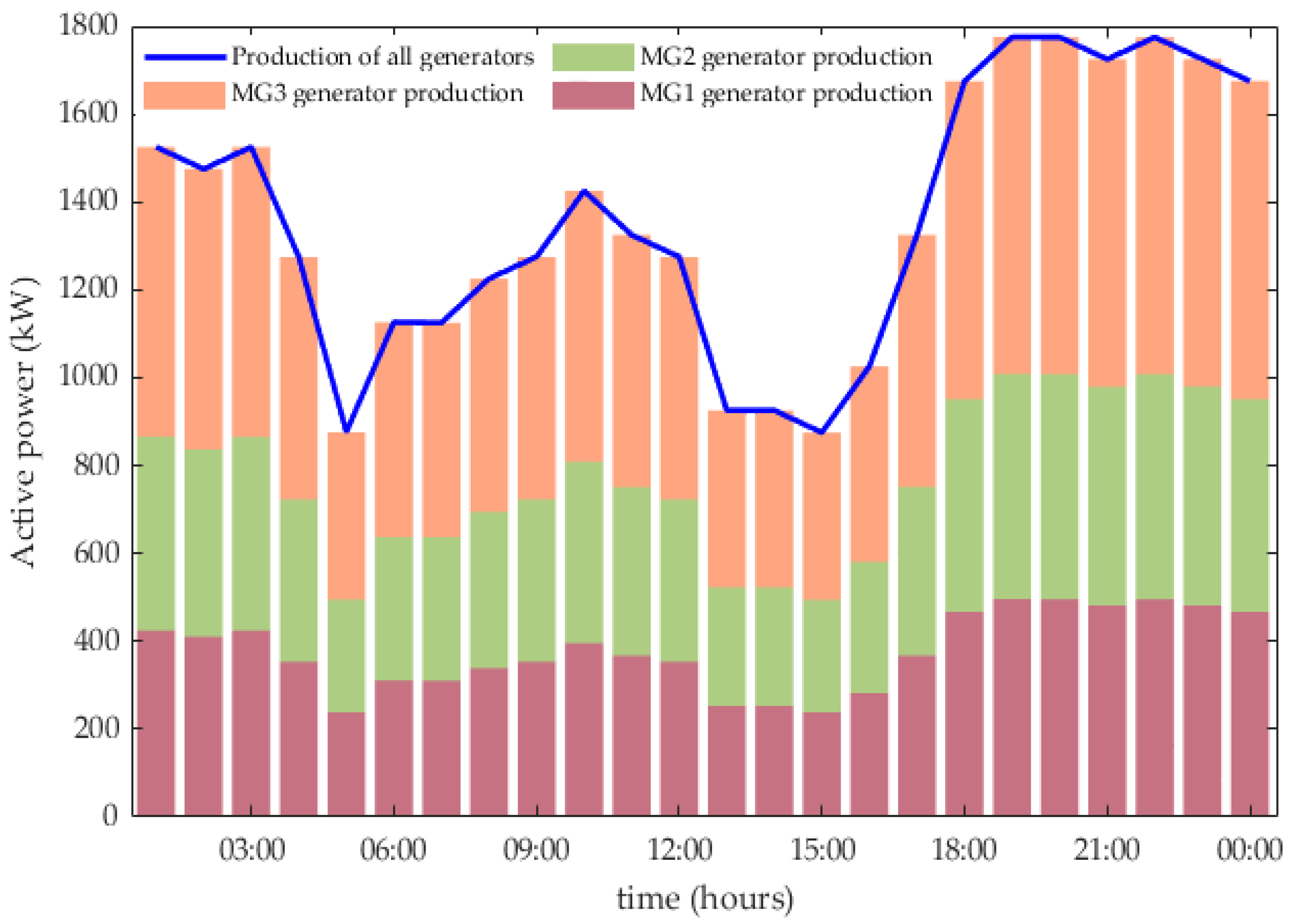
3.3. Auxiliary Generator Modeling

The generator fuel cost function FC depends on the power that is produced by the gth generator P g and may be accurately approximated by second-order polynomials [29]. Thus, the fuel cost of the gth generator at time t is given by Equation (14).
F C g P g t = a 0 g + a 1 g · P g t + a 2 g · P g t 2
where a 0 g , a 1 g , a 2 g denote the coefficients of the gth generator’s fuel cost function. The fuel consumption function (kgFuel/h) of the gth generator is given by Equation (15).
F u e l C o n P g t = F C g P g t F u e l C o s t g
where F u e l C o s t g is the cost of the fuel consumed by the gth generator (m.u./kgFuel).
It is assumed that GHG emissions are proportional to fuel consumption. Consequently, the fuel consumed by the g th generator is converted to the emitted C O 2 with a conversion factor of fuel mass to emission mass E m g , c e m , g (in k g E m g / k g F u e l ). The mass of the gas emissions produced in time interval Δ t is calculated using Equation (16).
m e m t = g c e m , g · F u e l C o n P g t · Δ t

3.4. Microgrid- and Energy Community-Level Load Modeling

The examined energy community is organized in interconnected microgrids. The total HVAC and electrical loads of each microgrid are obtained by summing the individual HVAC and electrical loads of all buildings within the microgrid. These aggregated loads are represented by Equations (17) and (18), respectively.
P H V A C , m g ( t ) = b     m g P H V A C , b ( t )
P e l , m g ( t ) = b     m g P e l , b ( t )
The total HVAC and electrical loads of the energy community are obtained by summing the HVAC and electrical loads of all microgrids within the community. These aggregated loads are represented by Equations (19) and (20), respectively.
P H V A C , E C ( t ) = m g     E C P H V A C , m g ( t )
P e l , E C ( t ) = m g     E C P e l , m g ( t )
where b/mg denote the index indicating the number of the building/microgrid, respectively; EC stands for energy community; P H V A C , b / P H V A C , m g / P H V A C , E C denote the HVAC electric power consumption of a building/microgrid/energy community, respectively; and P e l , b / P e l , m g / P e l , E C denote the power consumption of electrical loads of a building/microgrid/energy community, respectively.

4. Optimization of Energy Community Operation

The proposed system is structured into two optimization levels which are described in detail in this section. In this work, Particle Swarm Optimization (PSO) is employed to optimally schedule the operation of the examined energy community. PSO is one of the most highly efficient heuristic methods and is remarkably simple to implement. PSO has proved to be very robust and efficient for application to complex optimization problems as it does not depend on the selected initial point and leads to a global optimum with a high rate of success. However, it should be noted that no optimization method can guarantee convergence to the global optimum with a 100% rate of success. Usually, it is difficult to find the global optimum for large-dimension optimization problems and formulate extremely complex objective functions and constraints with classical methods. However, using the PSO algorithm, this problem does not occur since the objective function can be arbitrarily complex and of any form. It can also be simply adjusted in case new components need to be included.

4.1. First Optimization Level

The first optimization level aims to determine the optimal operation schedule for each microgrid’s PEV aggregator, while ensuring adherence to all relevant PEV constraints. The algorithm estimates the optimal active power of each PEV aggregator to minimize their daily operational costs. The augmented cost function employed in the PSO framework is given in Equation (21).
min P ag , mg m g     E C t P a g , m g ( t ) · E P ( t ) · Δ t
It is subject to the following constraints:
Minimum and maximum power of PEV aggregator constraint:
P a g , m i n , m g t P a g , m g t P a g , m a x , m g t
Minimum and maximum stored energy of PEV aggregator constraint:
S o C a g , m i n , m g t S o C a g , m g t Δ t P a g , m g t · Δ t S o C a g , m a x , m g t

4.2. Second Optimization Level

The second optimization level aims to minimize the energy community’s daily operational costs by optimally scheduling local generator units. Moreover, it seeks to achieve net-zero energy exchange with the main grid, reduce transmission line power losses, and lower GHG emissions from generators. This approach also ensures adherence to distribution line capacity constraints and the operational and technical limitations of generators.
Additional information regarding the optimization of generators is provided next. Let N g represent the number of generators of the energy community. Each dimension of the particle contains a value, S , which ranges from 0 to 2 N g 1 and corresponds to the operation state of the generator set. This value is then converted into a binary number that reflects the operation state of each generator, s t g .
The objective function of the optimization problem is given by Equation (24). The PSO method was used to solve the constrained optimization problem defined in (24)–(31).
min st g , P g t P g r i d t · E P t + t g s t g t · F C g P g t · Δ t
It is subject to the following constraints:
Energy community power balance constraint:
P H V A C , E C t + P e l , E C t + k 3 · I l i n e , k ( t ) 2 · R k m g     E C P a g , m g t m g     E C P R E S , m g t g P g t P g r i d t = 0
Minimum and maximum power exchanged with main grid constraint:
P g r i d , m i n P g r i d ( t ) P g r i d , m a x
Net-zero energy constraint:
t P g r i d ( t ) · Δ t = 0
  • Minimum and maximum power of generators constraint:
    s t g ( t ) · P g , m i n s t g ( t ) · P g t s t g ( t ) · P g , m a x
  • GHG emissions constraint:
    t m e m t < E m m a x
  • Minimum and maximum transmission line power constraints:
    P l i n e , m i n < P l i n e , k ( t ) < P l i n e , m a x
Microgrid power balance constraint:
P H V A C , m g t + P e l , m g t P a g , m g t P R E S , m g t P m g t + j m g P m g , j t s t m g · P g r i d , m g t = 0 ,     m g
where E P is the electricity price; P g r i d is the power that EC exchanges with the main grid; P g r i d , m i n / P g r i d , m a x are the minimum and maximum power that EC can exchange with the main grid; P g r i d , m g is the power that the mgth microgrid exchanges with the main grid; P R E S , m g is the power produced by the RESs of the mgth microgrid; P g , m i n / P g , m a x are the upper and lower power bounds of the gth generator; E m m a x is the total emission upper limit of generators; the k index denotes the number of a distribution line connecting the microgrids of the energy community; I l i n e , k is the current of the kth distribution line; the j index denotes the number of microgrids to which the mg microgrid is interconnected; P m g , j is the power exchanged between microgrids mg and j; P l i n e , k is the power flowing in the kth distribution line; R k is the resistance of the k line; s t m g denotes if there is a connection point between the mgth microgrid and the main grid; and P l i n e , m i n / P l i n e , m a x are the lines’ lower/upper power bounds.

5. Results

The developed models and algorithms were verified through the simulation of three realistic energy community operation scenarios. In the first scenario (SC1), the objective was to minimize the energy community’s daily operational costs while ensuring compliance with all technical and operational constraints, including those of PEVs, local generators, power exchanged with the main grid, and the maximum transfer capacity of the lines interconnecting the microgrids of the energy community. In the second scenario (SC2), an additional constraint was applied to achieve net-zero energy exchange with the main grid, ensuring that the total energy exchanged over a 24 h period equals zero. In the third scenario (SC3), an additional constraint was applied to limit the generators’ total GHG emissions to a predefined threshold.
The PEV model data are given in Table 1. Table 2 contains the data of local generators. Table 3 includes the capacity limits of the distribution lines connecting the microgrids, along with the power exchange thresholds between the energy community and the grid.
In our study, although the core optimization framework operates under deterministic inputs, we also conducted a sensitivity analysis to account for the inherent uncertainty in electricity prices, RES availability, and load consumption. Specifically, multiple stochastic trajectories for each of these variables were randomly generated to simulate realistic fluctuations and assess the robustness of the proposed methodology. Figure 2 illustrates the base electricity price trajectory selected for demonstration purposes, along with the associated variation area that captures potential deviations. The electricity price data used for the optimization framework corresponds to an actual daily System Marginal Price (SMP) of the Greek electricity market. The SMP is the wholesale market-clearing price and is published by the Independent Power Transmission Operator (IPTO) of Greece. Figure 3 shows the number of connected PEVs of each microgrid. Figure 4a–c depict the RES production trajectories and their variations for Microgrids 1, 2, and 3, respectively. Figure 5a–c show the residential building load profiles with associated uncertainties for Microgrids 1, 2 and 3, respectively.
Figure 6a,b illustrate the active power and total energy stored in the PEV aggregator of the first microgrid, respectively, along with their upper and lower bounds. Similarly, Figure 7a,b depict the respective results for the PEV aggregator in the second microgrid, while Figure 8a,b present the same information for the third microgrid. For all three PEV aggregators, power absorption occurs during periods of low electricity prices, whereas power injection is observed during periods of high electricity prices. The results for the optimal power of the microgrids’ PEV aggregators remain consistent across all three operation scenarios, as they are determined during the first optimization level. Since the variations between the scenarios pertain solely to the second optimization level, the outcomes of the first level remain unaffected.
The active power of each microgrid’s PEV aggregator is presented in Figure 9. Figure 10 illustrates the power output of each microgrid’s generators, along with the total production from all generators for SC1. Figure 11 depicts the active power that the energy community exchanges with the main electric grid for SC1. It is observed that during periods of low electricity prices, the main grid supplies power to the energy community, whereas during high electricity price periods, the energy community tends to inject power into the main grid, aligning with the optimization objective of minimizing the energy community’s daily operational costs. Figure 12 shows the active power exchanged between the interconnected microgrids within the energy community for SC1.
Figure 13 illustrates the power output of each microgrid’s generators, along with the total production from all generators for SC2. Figure 14 depicts the active power that the energy community exchanges with the main electric grid for SC2. Figure 15 shows the active power exchange between the interconnected microgrids within the energy community for SC2. A comparison between the SC1 and SC2 operation scenarios shows notable differences in the power exchanged between the energy community and the main grid, with SC2 exhibiting increased power injection into the main grid. This is attributed to the additional constraint in SC2, which requires net-zero energy exchange with the main grid. As illustrated in Figure 14, the total energy exchanged over a 24 h period is confirmed to be zero. In comparison to SC1, the local generators of the microgrids in SC2 produce more power to achieve net-zero energy exchange with the main grid.
Figure 16 illustrates the power output of each microgrid’s generators, along with the total power production of all generators for SC3. Figure 17 depicts the active power that the energy community exchanges with the main electric grid for SC3. Figure 18 shows the active power exchanged between the interconnected microgrids within the energy community for SC3. Minor differences exist between SC2 and SC3, as in SC3, the objective is to achieve near-net-zero energy exchange with the main grid while limiting the total GHG emissions of the local generators to a predefined threshold.
Figure 19 and Figure 20 depict the total power produced by the generators of the energy community and the active power that the energy community exchanges with the main grid for all examined scenarios, respectively.
The full two-stage model, including all constraints and objective components, was solved within approximately 20 s using the PSO algorithm. This confirms that the proposed method is computationally efficient and suitable for operation scheduling applications in real-world energy communities. Table 4 presents the daily operational costs of the energy community for each examined scenario. The slight increase of 2.47% in the operational costs observed in SC3, when environmental constraints were added to limit GHG emissions from local generators, is indeed reasonable. This cost increase reflects the trade-off between achieving environmental sustainability and minimizing operational costs. The limit that we set on GHG emissions was designed to ensure a meaningful reduction in emissions, but as expected, imposing stricter environmental restrictions can lead to higher operational costs due to the increased reliance on the main grid. The extent of the cost increase depends on the specific reduction rate of GHG emissions that was chosen in this study. The results of the sensitivity analysis show that the proposed optimization framework remains robust under uncertainty, with the average increase, compared to SC1, in the daily operational costs of the energy community being only 1.27% across the examined scenarios. This marginal impact demonstrates the resilience and effectiveness of the proposed framework under practical, variable conditions, while maintaining compliance with all operational and technical constraints.

6. Conclusions

This study presents a method for the optimal and sustainable operation of energy communities organized in interconnected microgrids. The proposed algorithm minimizes the energy community’s daily operational costs by optimizing power sharing among interconnected microgrids, regulating local generators, and effectively managing PEVs. Additionally, this approach seeks to achieve net-zero energy exchange with the main grid, reduce GHG emissions, and decrease power losses in the electricity distribution lines interconnecting the microgrids, while adhering to various technical and operational constraints. To validate the effectiveness of the proposed methodology, three operation scenarios of the energy community were simulated. In SC1, the objective was to minimize the daily operational costs of the energy community while adhering to all technical and operational constraints. SC2 introduced an additional constraint to achieve net-zero energy exchange with the main grid over a 24 h period. SC3 further imposed a limit on total GHG emissions from local generators. Incorporating additional constraints into the optimization problem leads to a slight increase, in the range of 2.47%, in the energy community’s operational costs. The simulation results demonstrate the robustness of the developed models and algorithms in optimizing energy community operation while promoting economic efficiency and environmental sustainability.
In future work, we will explore the combined use of conventional ESSs alongside PEVs within our proposed framework. By incorporating both technologies, we aim to enhance the system’s ability to improve energy storage efficiency. This combined approach is expected to strengthen the economic performance of the microgrids, offering even greater operational flexibility and resilience compared to using PEVs or ESSs alone. Moreover, a moving window update mechanism could be adopted in future work, ensuring that the proposed EMS remains responsive and flexible, continuously adapting to the uncertainty of RESs and electricity consumption. The EMS will recalculate an optimal operation scheduling using a receding optimization horizon, allowing microgrids to dynamically adjust to real-time fluctuations in renewable generation and energy demand. A comparison of PSO performance with other heuristic optimization methods will also be made. Future work will aim to extend the current methodology toward real-time operation frameworks, integrating ancillary services for voltage and frequency regulation, particularly under high renewable penetration and dynamic load conditions.

Author Contributions

Conceptualization, F.D.K.; Methodology, F.D.K.; Software, D.G.K., E.K.K. and F.D.K.; Validation, F.D.K., E.K.K. and D.G.K.; Formal Analysis, F.D.K., D.G.K. and E.K.K.; Investigation, F.D.K., E.K.K. and D.G.K.; Resources, F.D.K.; Data Curation, F.D.K.; Writing—Original Draft Preparation, D.G.K. and E.K.K.; Writing—Review and Editing, F.D.K., E.K.K. and D.G.K.; Visualization, F.D.K.; Supervision, F.D.K.; Project administration, F.D.K. All authors have read and agreed to the published version of the manuscript.

Funding

This research received no external funding.

Data Availability Statement

The original contributions presented in this study are included in the article. Further inquiries can be directed to the corresponding author.

Conflicts of Interest

The authors declare no conflicts of interest.

References

  1. Dorahaki, S.; Rashidinejad, M.; Ardestani, S.F.F.; Abdollahi, A.; Salehizadeh, M.R. An integrated model for citizen energy communities and renewable energy communities based on clean energy package: A two-stage risk-based approach. Energy 2023, 277, 127727. [Google Scholar] [CrossRef]
  2. Cosic, A.; Stadler, M.; Mansoor, M.; Zellinger, M. Mixed-integer linear programming based optimization strategies for renewable energy communities. Energy 2021, 237, 121559. [Google Scholar] [CrossRef]
  3. Weckesser, T.; Dominković, D.F.; Blomgren, E.M.V.; Schledorn, A.; Madsen, H. Renewable Energy Communities: Optimal sizing and distribution grid impact of photovoltaics and battery storage. Appl. Energy 2021, 301, 117408. [Google Scholar] [CrossRef]
  4. Gomes, L.; Vale, Z. Costless renewable energy distribution model based on cooperative game theory for energy communities considering its members’ active contributions. Sustain. Cities Soc. 2024, 101, 105060. [Google Scholar] [CrossRef]
  5. Sudhoff, R.; Schreck, S.; Thiem, S.; Niessen, S. Operating Renewable Energy Communities to Reduce Power Peaks in the Distribution Grid: An Analysis on Grid-Friendliness, Different Shares of Participants, and Economic Benefits. Energies 2022, 15, 5468. [Google Scholar] [CrossRef]
  6. Gjorgievski, V.Z.; Cundeva, S.; Georghiou, G.E. Social arrangements, technical designs and impacts of energy communities: A review. Renew. Energy 2021, 169, 1138–1156. [Google Scholar] [CrossRef]
  7. Maślak, G.; Orłowski, P. Microgrid Operation Optimization Using Hybrid System Modeling and Switched Model Predictive Control. Energies 2022, 15, 833. [Google Scholar] [CrossRef]
  8. Nazemi, S.D.; Mahani, K.; Ghofrani, A.; Amini, M.; Kose, B.E.; Jafari, M.A. Techno-Economic Analysis and Optimization of a Microgrid Considering Demand-Side Management. In Proceedings of the 2020 IEEE Texas Power and Energy Conference (TPEC), College Station, TX, USA, 6–7 February 2020; pp. 1–6. [Google Scholar] [CrossRef]
  9. Jiang, Q.; Xue, M.; Geng, G. Energy Management of Microgrid in Grid-Connected and Stand-Alone Modes. In Proceedings of the IEEE Transactions on Power Systems, New York, NY, USA, 7 March 2013; IEEE: New York, NY, USA, 2013; Volume 28, pp. 3380–3389. [Google Scholar] [CrossRef]
  10. Hussain, A.; Kim, H.-M. A Rule-Based Modular Energy Management System for AC/DC Hybrid Microgrids. Sustainability 2025, 17, 867. [Google Scholar] [CrossRef]
  11. Wang, Z.; Chen, B.; Wang, J.; Kim, J.; Begovic, M.M. Robust Optimization Based Optimal DG Placement in Microgrids. In Proceedings of the IEEE Transactions on Smart Grid, New York, NY, USA, 8 September 2014; IEEE: New York, NY, USA, 2014; Volume 5, pp. 2173–2182. [Google Scholar] [CrossRef]
  12. Zhang, M.; Chen, J. The Energy Management and Optimized Operation of Electric Vehicles Based on Microgrid. In Proceedings of the IEEE Transactions on Power Delivery, New York, NY, USA, 13 May 2014; IEEE: New York, NY, USA, 2014; Volume 29, pp. 1427–1435. [Google Scholar] [CrossRef]
  13. Kampezidou, S.; Vasios, O.; Meliopoulos, S. Multi-Microgrid Architecture: Optimal Operation and Control. In Proceedings of the 2018 North American Power Symposium (NAPS), Fargo, ND, USA, 9–11 September 2018; pp. 1–5. [Google Scholar] [CrossRef]
  14. Acosta, M.N.; Gonzalez-Longatt, F.; Topić, D.; Andrade, M.A. Optimal Microgrid–Interactive Reactive Power Management for Day–Ahead Operation. Energies 2021, 14, 1275. [Google Scholar] [CrossRef]
  15. Shuai, Z.; Sun, Y.; Shen, Z.J.; Tian, W.; Tu, C.; Li, Y.; Yin, X. Microgrid stability: Classification and a review. Renew. Sustain. Energy Rev. 2016, 58, 167–179. [Google Scholar] [CrossRef]
  16. Zhang, L.; Ruan, Z.; Li, S.; Wu, S. Cooperative operation optimization for rural multi-microgrid and county-integrated energy operators considering typical energy scenarios. J. Renew. Sustain. Energy 2024, 16, 044703. [Google Scholar] [CrossRef]
  17. Ye, T.; Huang, Y.; Yang, W.; Cai, G.; Yang, Y.; Pan, F. Safe multi-agent deep reinforcement learning for decentralized low-carbon operation in active distribution networks and multi-microgrids. Appl. Energy 2025, 387, 125609. [Google Scholar] [CrossRef]
  18. Moungos, K.A.; Kyriakou, D.G.; Kanellos, F.D. Towards the integration of interconnected microgrids to deregulated electricity markets. Electr. Power Syst. Res. 2025, 239, 111264. [Google Scholar] [CrossRef]
  19. Merabet, A.; Al-Durra, A.; El-Fouly, T.; El-Saadany, E.F. Optimization and energy management for cluster of interconnected microgrids with intermittent non-polluting and diesel generators in off-grid communities. Electr. Power Syst. Res. 2025, 241, 111319. [Google Scholar] [CrossRef]
  20. Han, D.; Lee, J.H. Two-stage stochastic programming formulation for optimal design and operation of multi-microgrid system using data-based modeling of renewable energy sources. Appl. Energy 2021, 291, 116830. [Google Scholar] [CrossRef]
  21. Kyriakou, D.G.; Kanellos, F.D.; Tsekouras, G.J.; Moungos, K.A. Effective and Local Constraint-Aware Load Shifting for Microgrid-Based Energy Communities. Energies 2025, 18, 343. [Google Scholar] [CrossRef]
  22. Barone, G.; Brusco, G.; Menniti, D.; Pinnarelli, A.; Sorrentino, N.; Vizza, P.; Burgio, A.; ABayod-Rújula, Á. A Renewable Energy Community of DC Nanogrids for Providing Balancing Services. Energies 2021, 14, 7261. [Google Scholar] [CrossRef]
  23. Wu, P.; Huang, W.; Tai, N.; Liang, S. A novel design of architecture and control for multiple microgrids with hybrid AC/DC connection. Appl. Energy 2018, 210, 1002–1016. [Google Scholar] [CrossRef]
  24. Hou, H.; Wang, Z.; Chen, Y.; Wang, Q.; Zhao, B.; Zhang, Q.; Xie, C. Multi-stage hybrid energy management strategy for reducing energy abandonment and load losses among multiple microgrids. Int. J. Electr. Power Energy Syst. 2023, 148, 108773. [Google Scholar] [CrossRef]
  25. Zou, H.; Mao, S.; Wang, Y.; Zhang, F.; Chen, X.; Cheng, L. A Survey of Energy Management in Interconnected Multi-Microgrids. IEEE Access 2019, 7, 72158–72169. [Google Scholar] [CrossRef]
  26. Santos, A.; McGuckin, N.; Nakamoto, H.Y.; Gray, D.; Liss, S. Summary of Travel Trends: 2009 National Household Travel Survey; US Department of Transportation; Federal Highway Admin: Washington, DC, USA, 2011. Available online: http://nhts.ornl.gov/2009/pub/stt.pdf (accessed on 1 April 2025).
  27. Kyriakou, D.G.; Kanellos, F.D. Energy and power management system for microgrids of large—Scale building prosumers. IET Energy Syst. Integr. 2023, 5, 228–244. [Google Scholar] [CrossRef]
  28. Kyriakou, D.G.; Kanellos, F.D. Optimal Operation of Microgrids Comprising Large Building Prosumers and Plug-In Electric Vehicles Integrated into Active Distribution Networks. Energies 2022, 15, 6182. [Google Scholar] [CrossRef]
  29. Kanellos, F.D. Optimal power management with GHG emissions limitation in all-electric ship power systems comprising energy storage systems. IEEE Trans. Power Syst. 2014, 29, 330–339. [Google Scholar] [CrossRef]
Figure 1. Configuration of the proposed system.
Energies 18 02087 g001
Figure 2. Electricity price.
Energies 18 02087 g002
Figure 3. Number of connected PEVs of each microgrid.
Energies 18 02087 g003
Figure 4. RES production of (a) Microgrid 1, (b) Microgrid 2, and (c) Microgrid 3.
Energies 18 02087 g004
Figure 5. Residential building loads of (a) Microgrid 1, (b) Microgrid 2, and (c) Microgrid 3.
Energies 18 02087 g005
Figure 6. (a) Active power of PEV aggregator—MG1. (b) Stored energy of PEV aggregator—MG1.
Energies 18 02087 g006
Figure 7. (a) Active power of PEV aggregator—MG2. (b) Stored energy of PEV aggregator—MG2.
Energies 18 02087 g007
Figure 8. (a) Active power of PEV aggregator—MG3. (b) Stored energy of PEV aggregator—MG3.
Energies 18 02087 g008
Figure 9. Active power of PEV aggregator of each microgrid.
Energies 18 02087 g009
Figure 10. Power produced by the generators of each microgrid and total production of all generators—SC1.
Energies 18 02087 g010
Figure 11. Active power that the energy community exchanges with the main electric grid—SC1.
Energies 18 02087 g011
Figure 12. Power exchanged between the interconnected microgrids of the energy community—SC1.
Energies 18 02087 g012
Figure 13. Power produced by the generators of each microgrid and total production of all generators—SC2.
Energies 18 02087 g013
Figure 14. Active power that the energy community exchanges with the main electric grid—SC2.
Energies 18 02087 g014
Figure 15. Power exchanged between the interconnected microgrids of the energy community—SC2.
Energies 18 02087 g015
Figure 16. Power produced by the generators of each microgrid and total production of all generators—SC3.
Energies 18 02087 g016
Figure 17. Active power that the energy community exchanges with the main electric grid—SC3.
Energies 18 02087 g017
Figure 18. Power exchanged between the interconnected microgrids of the energy community—SC3.
Energies 18 02087 g018
Figure 19. Total power produced by the generators of the energy community for all examined scenarios.
Energies 18 02087 g019
Figure 20. Power that the energy community exchanges with the main grid for all examined scenarios.
Energies 18 02087 g020
Table 1. PEV data.
Table 1. PEV data.
PEV Type1234
Battery capacity (kWh)774526.866.5
S o C m a x / S o C m i n (kWh)69.3/7.740/4.524.12/2.760/6.65
P m a x / P m i n (kW)11/−117.2/−7.26.6/−6.611/−11
Table 2. Generator technical characteristics.
GEN1GEN2GEN3
Technical minimum (kW)125150200
Technical maximum (kW)500600800
Consumed fuel cost (m.u./h) 25.5 0.0845 · P +
+ 3 · 10 4 · P 2
30.5 0.0945 · P +
+ 3 · 10 4 · P 2
36.8 0.0936 · P +
+ 2 · 10 4 · P 2
Table 3. Transmission line capacity limits.
Transmission line capacity limits (kW), P l i n e , m i n / P l i n e , m a x −1000/1000
Power limits exchanged with the main grid (kW), P g r i d , m i n / P g r i d , m a x −1000/3000
Table 4. Operation scenarios.
Operation ScenarioSC1SC2SC3
Optimization of EC operation
Net-zero energy exchange-
GHG emissions limitation--
Daily operational costs (m.u.)395240524155
Disclaimer/Publisher’s Note: The statements, opinions and data contained in all publications are solely those of the individual author(s) and contributor(s) and not of MDPI and/or the editor(s). MDPI and/or the editor(s) disclaim responsibility for any injury to people or property resulting from any ideas, methods, instructions or products referred to in the content.

