

TLP-Supported NREL 5MW Floating Offshore Wind Turbine Tower Vibration Reduction Under Aligned and Misaligned Wind-Wave Excitations

Abstract
:1. Introduction
2. Materials and Methods
2.1. OpenFAST Model of the Reference Wind Turbine
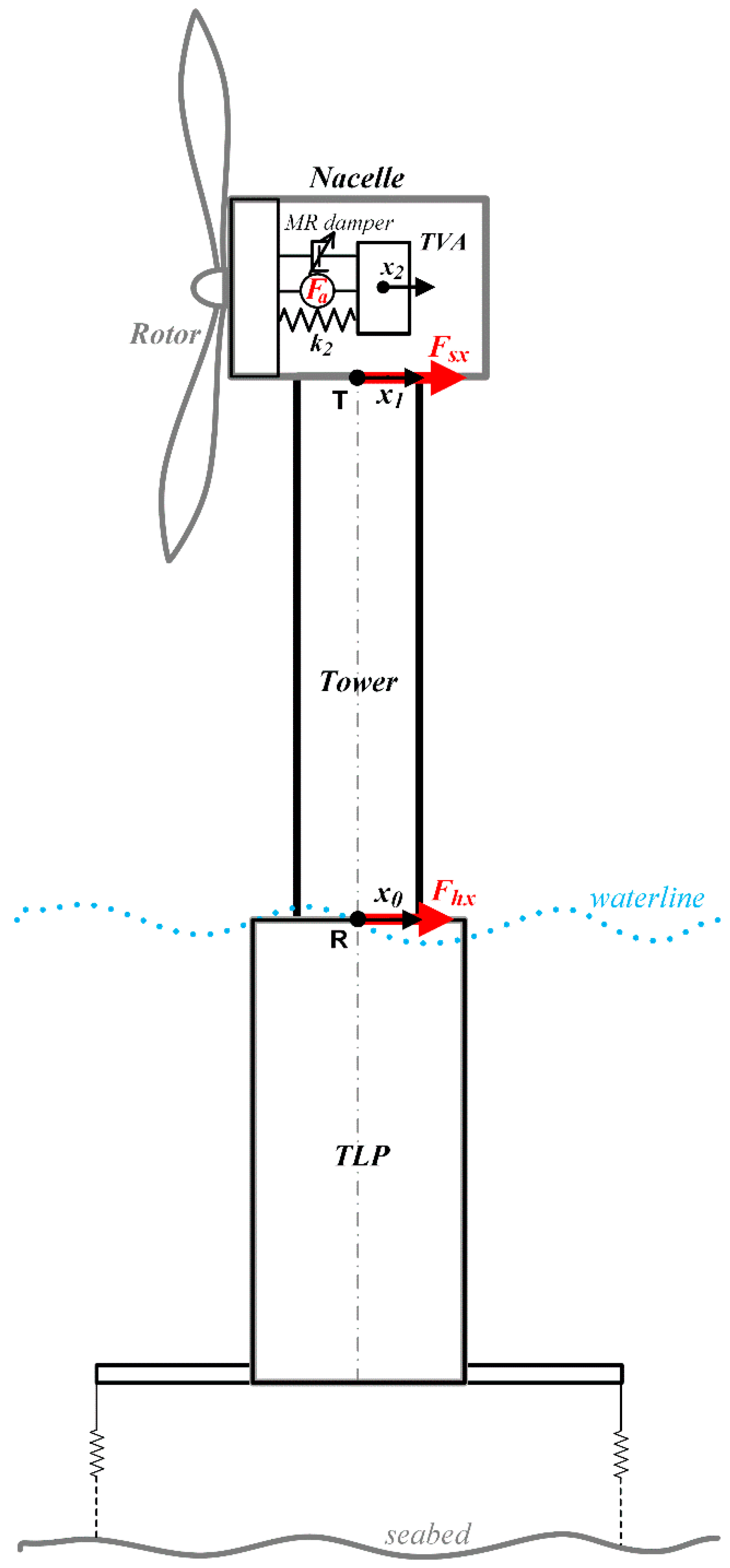
2.2. Tuned Vibration Absorber (TVA) for NREL 5MW Wind Turbine
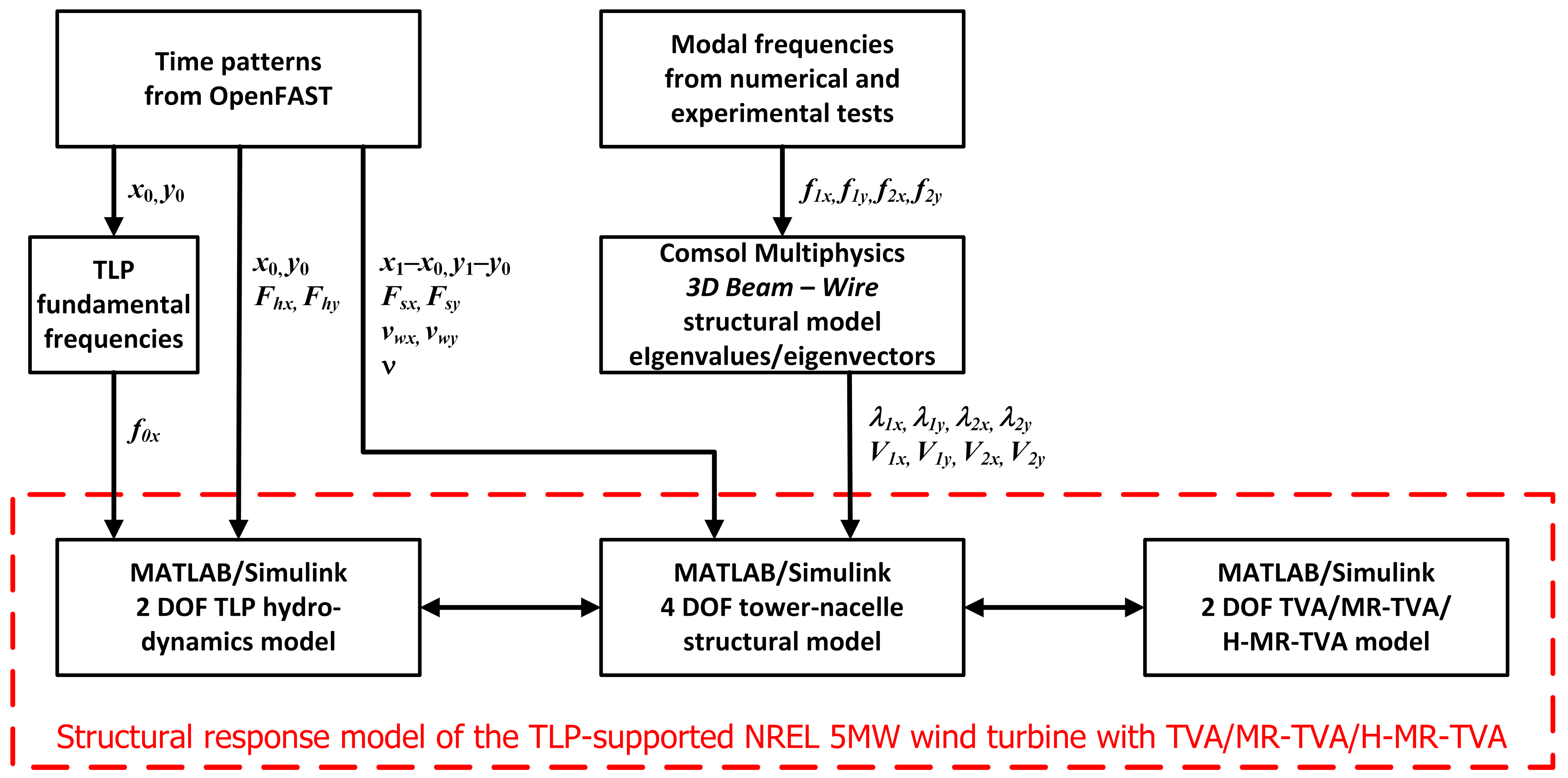
2.3. Comsol/MATLAB/Simulink Model
2.4. Comsol/MATLAB/Simulink Model Validation
2.5. Implementation of the TVA/MR-TVA/H-MR-TVA
2.6. Nonlinear Optimal Control Problem Formulation
3. Results
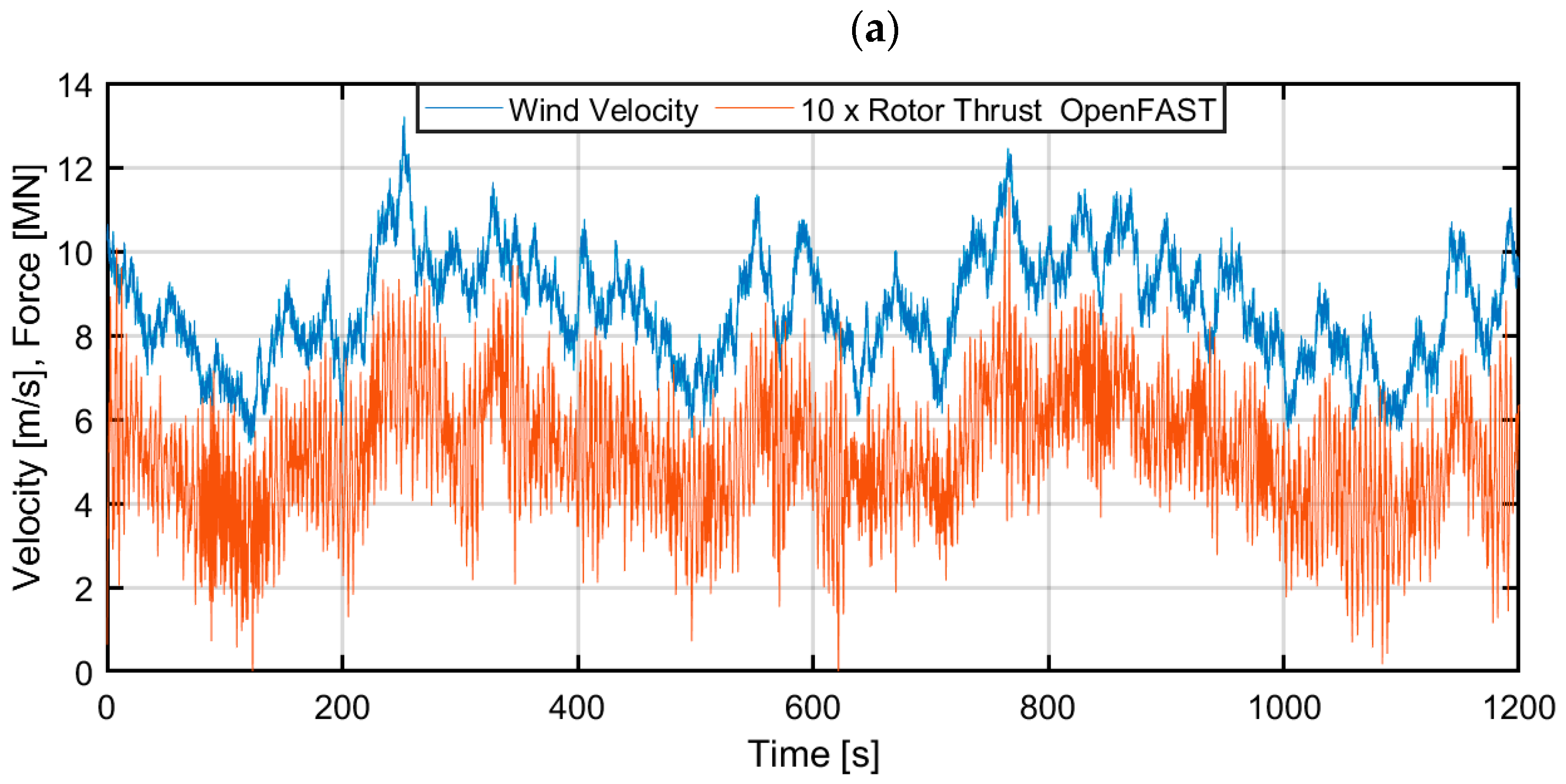
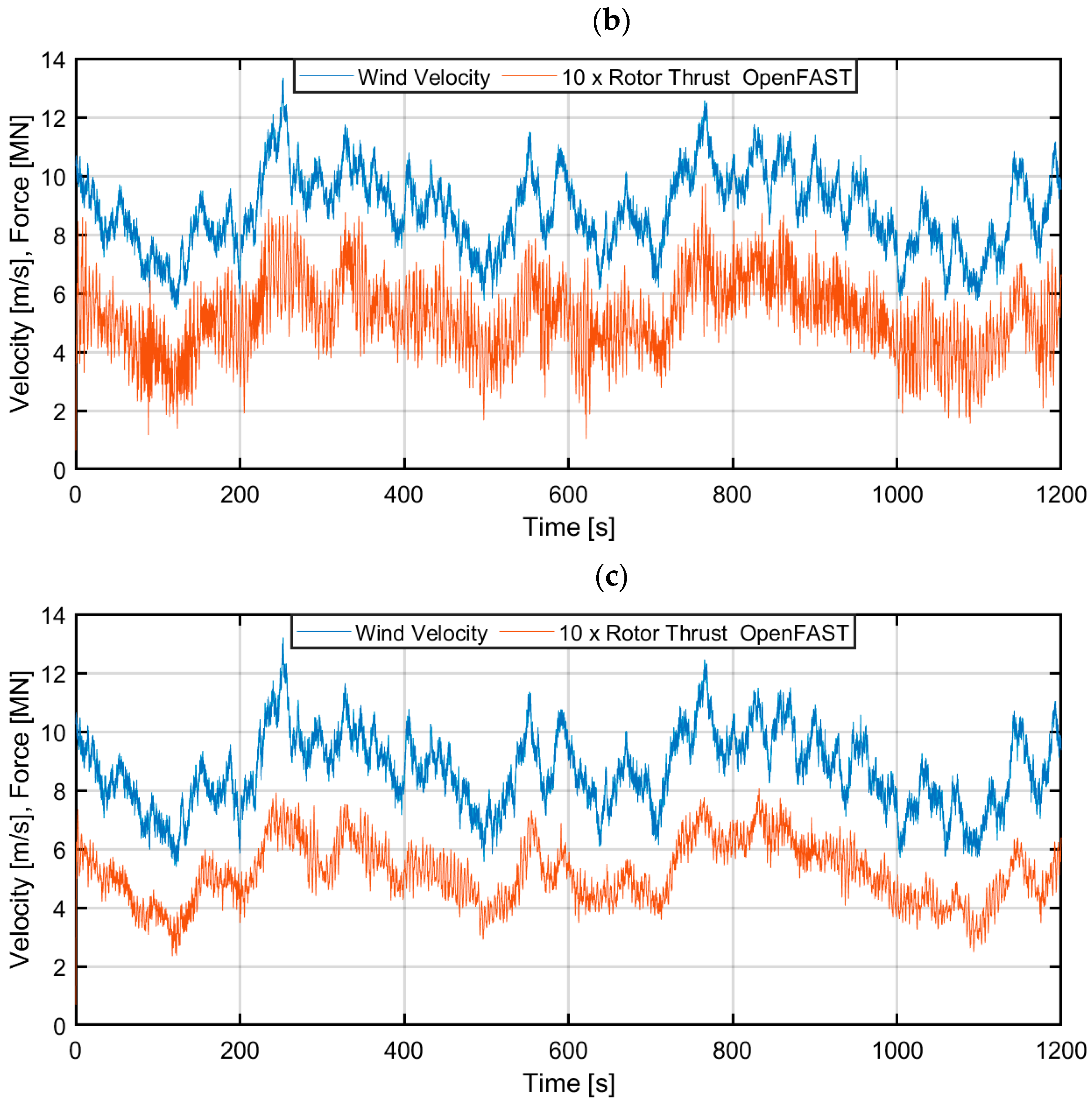
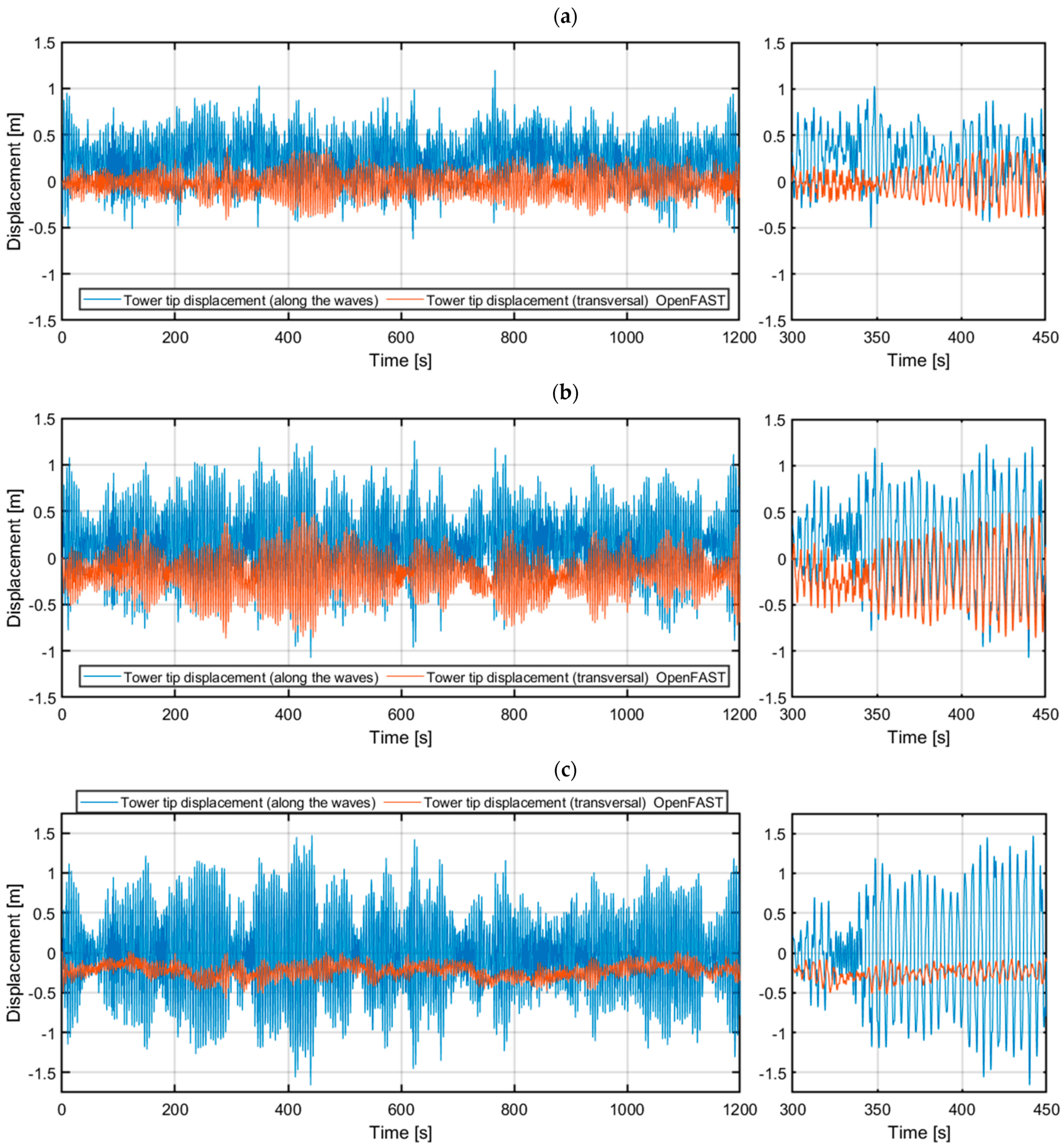
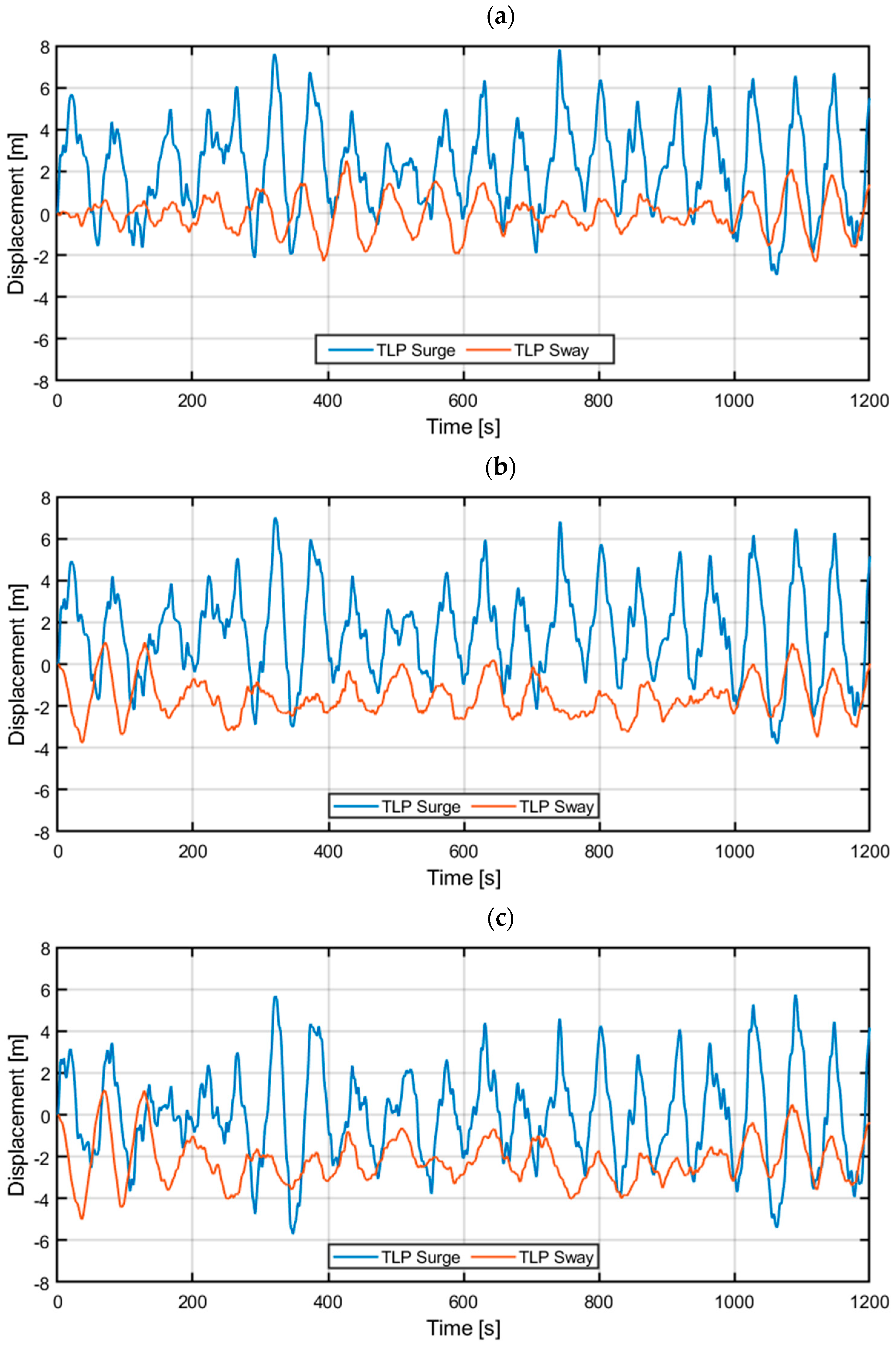
3.1. OpenFAST Model Analyses
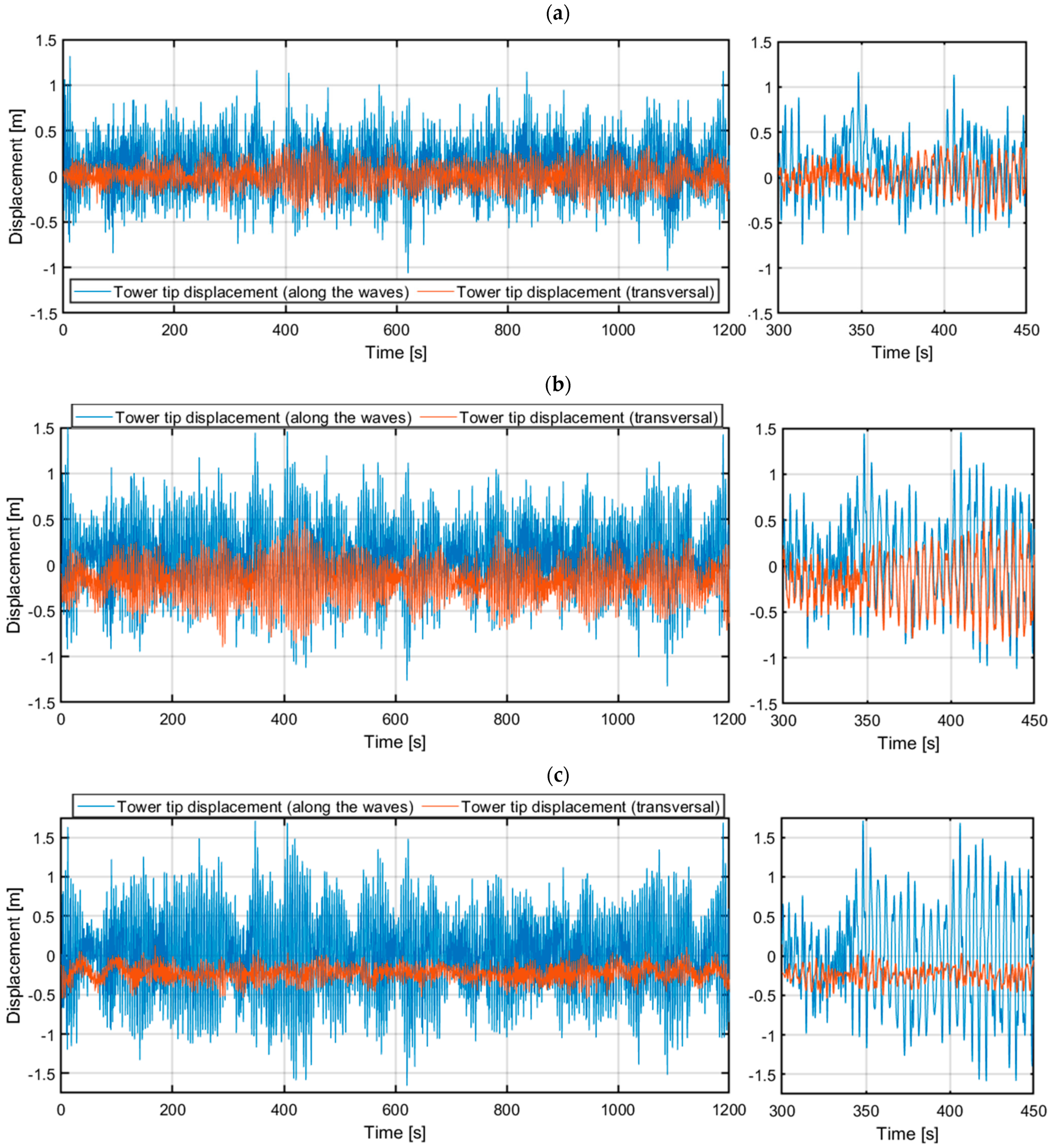
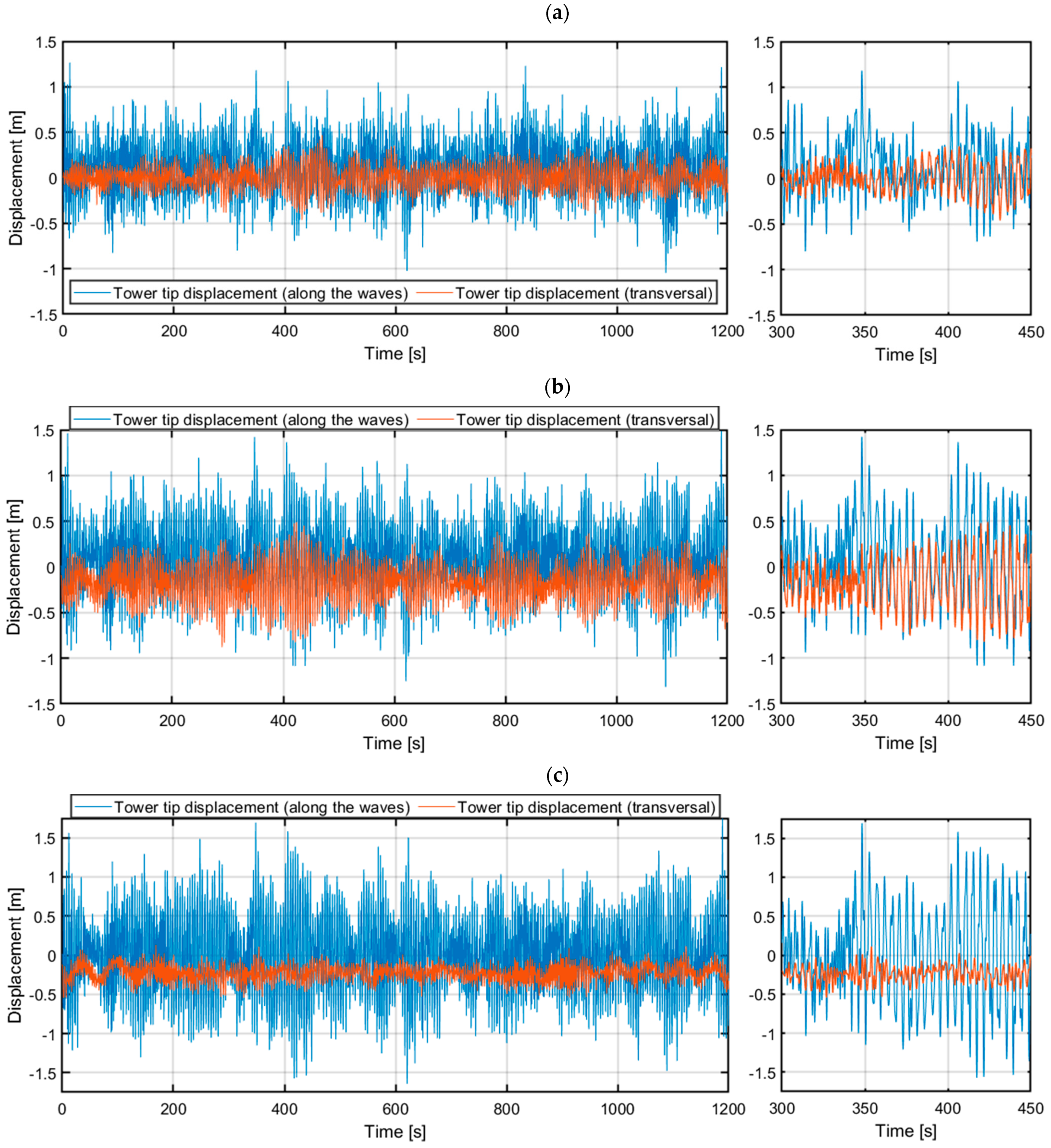
3.2. Comsol/MATLAB/Simulink Model Analyses
4. Discussion
5. Conclusions
Author Contributions
Funding
Data Availability Statement
Acknowledgments
Conflicts of Interest
References
- Global Wind Energy Council (GWEC). Global Offshore Wind Report 2022; GWEC: Brussels, Belgium, 2022. [Google Scholar]
- Henderson, A.R.; Witcher, D. Floating offshore wind energy—A review of the current status and an assessment of the prospects. Wind Eng. 2010, 34, 1–16. [Google Scholar] [CrossRef]
- Manwell, J.F.; McGowan, J.G.; Rogers, A.L. Wind Energy Explained: Theory, Design and Application; John Wiley & Sons: Hoboken, NJ, USA, 2002. [Google Scholar]
- Konispoliatis, D.; Mavrakos, S.A. Hydrodynamic Analysis of an Array of Interacting Free-Floating Oscillating Water Column Devices. Ocean Eng. 2016, 111, 179–197. [Google Scholar] [CrossRef]
- Jonkman, J.; Butterfield, S.; Musial, W.; Scott, G. Definition of a 5-MW Reference Wind Turbine for Offshore System Development; NREL/TP-500-38060; National Renewable Energy Laboratory: Golden, CO, USA, 2009.
- Sclavounos, P.D.; Tracy, C.; Kim, M.H. Floating offshore wind turbines: Responses in a seastate, pareto optimal designs, and economic assessment. In Proceedings of the ASME 2008 27th International Conference on Offshore Mechanics and Arctic Engineering. Volume 6: Nick Newman Symposium on Marine Hydrodynamics; Yoshida and Maeda Special Symposium on Ocean Space Utilization; Special Symposium on Offshore Renewable Energy, Estoril, Portugal, 15–20 June 2008. [Google Scholar]
- Wang, L.; Liang, Z.; Cai, M.; Zhang, Y.; Yan, J. Adaptive Structural Control of Floating Wind Turbine with Application of MR Damper. Energy Procedia 2019, 158, 254–259. [Google Scholar] [CrossRef]
- Wayman, E.N. Coupled Dynamics and Economic Analysis of Floating Wind Turbine Systems; Massachusetts Institute of Technology: Cambridge, MA, USA, 2006. [Google Scholar]
- Butterfield, S.; Musial, W.; Jonkman, J.; Sclavounos, P.; Wayman, E. Engineering challenges for floating offshore wind turbines. In Proceedings of the 2005 Copenhagen Offshore Wind Conference, Copenhagen, Denmark, 26–28 October 2005. [Google Scholar]
- Robertson, A.; Jonkman, J.; Masciola, M.; Song, H.; Goupee, A.; Coulling, A.; Luan, C. Definition of the Semisubmersible Floating System for Phase II of OC4; NREL/TP-5000-60601; National Renewable Energy Laboratory: Golden, CO, USA, 2014.
- Martynowicz, P. Experimental study on the optimal-based vibration control of a wind turbine tower using a small-scale electric drive with MR damper support. Energies 2022, 15, 9530. [Google Scholar] [CrossRef]
- Bryson, A.E.; Ho, Y.C. Applied Optimal Control; Taylor & Francis: Abingdon, UK, 1975. [Google Scholar]
- Roddier, D.; Cermelli, C.; Aubault, A.; Weinstein, A. WindFloat: A floating foundation for offshore wind turbines. J. Renew. Sustain. Energy 2010, 2, 033104. [Google Scholar] [CrossRef]
- Demetriou, D.; Nikitas, N. A Novel Hybrid Semi-Active Mass Damper Configuration for Structural Applications. Appl. Sci. 2016, 6, 397. [Google Scholar] [CrossRef]
- Martynowicz, P. Control of an MR Tuned Vibration Absorber for Wind Turbine Application Utilising the Refined Force Tracking Algorithm. J. Low Freq. Noise Vib. Act. Control 2017, 36, 339–353. [Google Scholar] [CrossRef]
- Goldasz, J.; Sapiński, B.; Jastrzebski, Ł. Assessment of the Magnetic Hysteretic Behaviour of MR Dampers through Sensorless Measurements. Shock. Vib. 2018. [Google Scholar] [CrossRef]
- Martynowicz, P. Nonlinear optimal-based vibration control for systems with MR tuned vibration absorbers. J. Low Freq. Noise Vib. Act. Control 2019, 38, 1607–1628. [Google Scholar] [CrossRef]
- Martynowicz, P. Real-time implementation of nonlinear optimal-based vibration control for a wind turbine model. J. Low Freq. Noise Vib. Act. Control 2019, 38, 1635–1650. [Google Scholar] [CrossRef]
- Martynowicz, P.; Santos, M. Structural vibration control of NREL 5.0 MW FOWT using optimal-based MR tuned vibration absorber. In Proceedings of the 21st IFAC World Congress, Berlin, Germany, 11–17 July 2020. [Google Scholar]
- Goldasz, J.; Sapiński, B.; Jastrzebski, Ł.; Kubík, M. Dual Hysteresis Model of MR Dampers. Front. Mater. 2020, 7, 236. [Google Scholar] [CrossRef]
- Madsen, F.J.; Nielsen, T.R.L.; Kim, T.; Bredmose, H.; Pegalajar-Jurado, A.; Mikkelsen, R.F.; Lomholt, A.K.; Borg, M.; Mirzaei, M.; Shin, P. Experimental analysis of the scaled DTU10MW TLP floating wind turbine with different control strategies. Renew. Energy 2020, 155, 330–346. [Google Scholar] [CrossRef]
- Martynowicz, P. Nonlinear Optimal-Based Vibration Control of a Wind Turbine Tower Using Hybrid vs. Magnetorheological Tuned Vibration Absorber. Energies 2021, 14, 5145. [Google Scholar] [CrossRef]
- Martynowicz, P.; Katsaounis, G.M.; Mavrakos, S.A. Comparison of Floating Offshore Wind Turbine Tower Deflection Mitigation Methods Using Nonlinear Optimal-Based Reduced-Stroke Tuned Vibration Absorber. Energies 2024, 17, 1507. [Google Scholar] [CrossRef]
- Jonkman, J. Dynamics Modeling and Loads Analysis of an Offshore Floating Wind Turbine. Ph.D. Thesis, University of Colorado, Boulder, CO, USA, 2007. [Google Scholar]
- Bir, G.; Jonkman, J. Modal Dynamics of Large Wind Turbines with Different Support Structures. In Proceeding of the ASME 2008 27th International Conference on Offshore Mechanics and Arctic Engineering, Estoril, Portugal, 15–20 June 2008. [Google Scholar]
- Jonkman, J.; Matha, D. A Quantitative Comparison of the Responses of Three Floating Platform Concepts. In Proceedings of the European Offshore Wind 2009 Conference and Exhibition, Stockholm, Sweden, 14–16 September 2009. [Google Scholar]
- Matha, D. Model Development and Loads Analysis of an Offshore Wind Turbine on a Tension Leg Platform, with a Comparison to Other Floating Turbine Concepts; NREL/SR-500-45891; National Renewable Energy Lab: Golden, CO, USA, 2009.
- Stewart, G.; Lackner, M. Offshore Wind Turbine Load Reduction Employing Optimal Passive Tuned Mass Damping Systems. IEEE Trans. Control Syst. Technol. 2013, 21, 4. [Google Scholar] [CrossRef]
- Park, S.; Lackner, M.A.; Cross-Whiter, J.; Tsouroukdissian, A.R.; La Cava, W. An investigation of passive and semi-active tuned mass dampers for a tension leg platform floating offshore wind turbine in ULS conditions. In Proceedings of the ASME 2016 35th International Conference on Ocean, Offshore and Arctic Engineering, Busan, Republic of Korea, 19–24 June 2016. [Google Scholar]
- Park, S.; Lackner, M.A.; Pourazarm, P.; Tsouroukdissian, A.R.; Cross-Whiter, J. An investigation on the impacts of passive and semiactive structural control on a fixed bottom and a floating offshore wind turbine. Wind Energy 2019, 22, 1451–1471. [Google Scholar] [CrossRef]
- Hu, Y.; He, E. Active structural control of a floating wind turbine with a stroke-limited hybrid mass damper. J. Sound Vib. 2017, 410, 447–472. [Google Scholar] [CrossRef]
- Galán-Lavado, A.; Santos, M. Analysis of the effects of the location of passive control devices on the platform of a floating wind turbine. Energies 2021, 14, 2850. [Google Scholar] [CrossRef]
- Vardaroglu, M.; Gao, Z.; Avossa, A.M.; Ricciardelli, F. Validation of a TLP wind turbine numerical model against model-scale tests under regular and irregular waves. Ocean Eng. 2022, 256, 111491. [Google Scholar] [CrossRef]
- Vardaroglu, M.; Gao, Z.; Avossa, A.M.; Ricciardelli, F. Numerical Investigation of a TLP Wind Turbine Under Wind and Wave Loads. In Proceedings of the XVII Conference of the Italian Association for Wind Engineering; Springer: Cham, Switzerland, 2022; pp. 227–238. [Google Scholar] [CrossRef]
- Akbari Zadeh, N.; Ryan, P.; O’Rourke, F. Numerical evaluation of floating offshore wind turbines considering a range of sea-state conditions. In Proceedings of the ECOS2024, Rhodes, Greece, 30 June–4 July 2024. [Google Scholar]
- Stewart, G.M.; Lackner, M.A. The Impact of Passive Tuned Mass Dampers and Wind–Wave Misalignment on Offshore Wind Turbine Loads. Eng. Struct. 2014, 73, 54–61. [Google Scholar] [CrossRef]
- Li, X.; Caichao, Z.; Fan, Z.; Chen, X.; Jianjun, T. Effects of the yaw error and the wind-wave misalignment on the dynamic characteristics of the floating offshore wind turbine. Ocean Eng. 2020, 199, 106960. [Google Scholar] [CrossRef]
- Fitzgerald, B.; McAuliffe, J.; Baisthakur, S.; Sarkar, S. Enhancing the reliability of floating offshore wind turbine towers subjected to misaligned wind-wave loading using tuned mass damper inerters (TMDIs). Renew. Energy 2023, 211, 522–538. [Google Scholar] [CrossRef]
- El Hamoud, R.; Alkhoury, P.; Aït-Ahmed, M.; Soubra, A.-H.; Schoefs, F.; Dib, R. Vibration and Fatigue Mitigation of a 5 MW Barge-Type Floating Offshore Wind Turbine Under Misaligned Wind and Wave Loadings. In Proceedings of the 43rd International Conference on Ocean, Offshore & Arctic Engineering, Singapore, 9–14 June 2024. [Google Scholar] [CrossRef]
- Katsaounis, G.M.; Polyzos, S.; Mavrakos, S.A. An Experimental Study of the Hydrodynamic Behavior of a TLP Platform for a 5MW Wind Turbine with OWC Devices. In Proceedings of the VII International Conference on Computational Methods in Marine Engineering, Nantes, France, 15–17 June 2017. [Google Scholar]
- Shen, Y.J.; Wang, L.; Yang, S.P.; Gao, G.S. Nonlinear dynamical analysis and parameters optimization of four semi-active on-off dynamic vibration absorbers. J. Vib. Control 2012, 19, 143–160. [Google Scholar] [CrossRef]
- Ramírez, A.; Tomás-Rodríguez, M.; Sierra-García, J.E.; Santos, M. Metaheuristic Optimized Semi-Active Structural Control Approaches for a Floating Offshore Wind Turbine. Appl. Sci. 2024, 14, 11368. [Google Scholar] [CrossRef]
- Weber, F.; Maślanka, M. Precise stiffness and damping emulation with MR dampers and its application to semi-active tuned mass dampers of Wolgograd Bridge. Smart Mater. Struct. 2014, 23, 15019. [Google Scholar] [CrossRef]
- Martynowicz, P. Tuned vibration absorber for wind turbine tower deflection mitigation adopting nonlinear optimal control technique—Experimental tests. In Proceedings of the ICCC 2024: 25th International Carpathian Control Conference, Krynica-Zdrój, Poland, 22–24 May 2024. [Google Scholar]
- Namik, H.; Rotea, M.; Lackner, M. Active Structural Control with Actuator Dynamics on a Floating Wind Turbine. In Proceedings of the 51st AIAA Aerospace Sciences Meeting including the New Horizons Forum and Aerospace Exposition, Grapevine, TX, USA, 7–10 January 2013. [Google Scholar]
- Villoslada, D.; Santos, M.; Tomás-Rodríguez, M. TMD Stroke Limiting Influence on Barge-Type Floating Wind Turbines. Ocean Eng. 2022, 248, 110781. [Google Scholar] [CrossRef]
- Ali, S.; Lee, S.-M.; Jang, C.-M. Techno-Economic Assessment of Wind Energy Potential at Three Locations in South Korea Using Long-Term Measured Wind Data. Energies 2017, 10, 1442. [Google Scholar] [CrossRef]
- Ali, S.; Park, H.; Lee, D. Multi-Criteria Optimization of Wind Turbines in an Offshore Wind Farm with Monopile Foundation Considering Structural Integrity and Energy Generation. J. Mar. Sci. Eng. 2024, 12, 2313. [Google Scholar] [CrossRef]
- Ali, S.; Park, H.; Lee, D. Investigating the Structural and Power Performance of a 15 MW Class Wind Energy Generation System under Experimental Wind and Marine Loading. J. Mar. Sci. Eng. 2024, 12, 1485. [Google Scholar] [CrossRef]
- Ali, S.; Park, H.; Noon, A.A.; Sharif, A.; Lee, D. Accuracy Testing of Different Methods for Estimating Weibull Parameters of Wind Energy at Various Heights above Sea Level. Energies 2024, 17, 2173. [Google Scholar] [CrossRef]
- Ali, S.; Lee, S.-M.; Jang, C.-M. Forecasting the Long-Term Wind Data via Measure-Correlate-Predict (MCP) Methods. Energies 2018, 11, 1541. [Google Scholar] [CrossRef]
- Wang, C.; Li, Z.; Xu, P.; Hou, Y.; Tan, D.; Li, L. Collision modeling approach and transient response mechanism of ring-ribbed cylindric shells for underwater vehicles. Appl. Math. Model. 2025, 141, 115923. [Google Scholar] [CrossRef]
- National Renewable Energy Laboratory (NREL). OpenFAST r-Test Repository. GitHub, 202X. Available online: https://github.com/OpenFAST/r-test (accessed on 16 October 2024).
- Den Hartog, J.P. Mechanical Vibrations; Dover Publications: Mineola, NY, USA, 1985. [Google Scholar]
- Ioffe, A.D.; Tihomirov, V.M. Theory of Extremal Problems; North-Holland Publishing Company: Amsterdam, The Netherlands, 1979. [Google Scholar]
- Jiang, J.; Lian, J.; Dong, X.; Zhou, H. Research on the along-wind aerodynamic damping and its effect on vibration control of offshore wind turbine. Ocean Eng. 2023, 274, 113993. [Google Scholar] [CrossRef]
- Martynowicz, P.; Ślimak, P. Vibration Analysis of TLP—NREL 5MW Floating Wind Turbine Under Different Wind-Wave Angles. Preprints 2025, 2025021358. [Google Scholar]
- Snamina, J.; Martynowicz, P. Prediction of characteristics of wind turbine’s tower-nacelle system from investigation of its scaled model. In Proceedings of the 6WCSCM: Sixth World Conference on Structural Control and Monitoring—Proceedings of the 6th Edition of the World Conference of the International Association for Structural Control and Monitoring (IACSM), Barcelona, Spain, 15–17 July 2014. [Google Scholar]


| Rotor Diameter | 126 m |
| Hub Height | 90 m |
| Wind Speed: | |
| Cut-In, Rated, Cut-Out | 3.0, 11.4, 25.0 m/s |
| Rotor Speed: Cut-In, Rated | 6.9, 12.1 rpm |
| Rotor Mass | 110.2 t |
| 240.0 t | |
| 347.5 t | |
| Nacelle Dimension | 18 × 6 × 6 m |
| Platform mass | 8600.41 t |
| Displacement | 12,179.6 m3 |
| Vertical centre of gravity of the platform (below sea level) | −40.612 m |
| Draft, freeboard | 47.89, 10–12 m |
| Water depth | 200 m |
| Water density | 1025 kg/m3 |
| Number of tendons | 8 |
| Nominal tendon pretension (each) | 3931 kN |
| Tendon diameter | 0.127 m |
| Tendon mass per unit length | 116.0 kg/m |
| Tendon axial stiffness modulus | 1.5 × 10⁹ N |
| TVA mass | 20 t |
| Spring stiffness | 28.0 kN/m |
| Damping coefficient | 2.8 kNs/m |
| Displacement limit | 10 m |
| Stop-bumper additional stiffness | 15.0 kN/m |
| Stop-bumper additional damping coeff. | 10.0 kNs/m |
| Installation height | 90 m |
| (a) | |||||||
| Modal Frequency | Comsol/MATLAB/Simulink Model | FAST Model [27] | Scaled Physical Model [33] | ||||
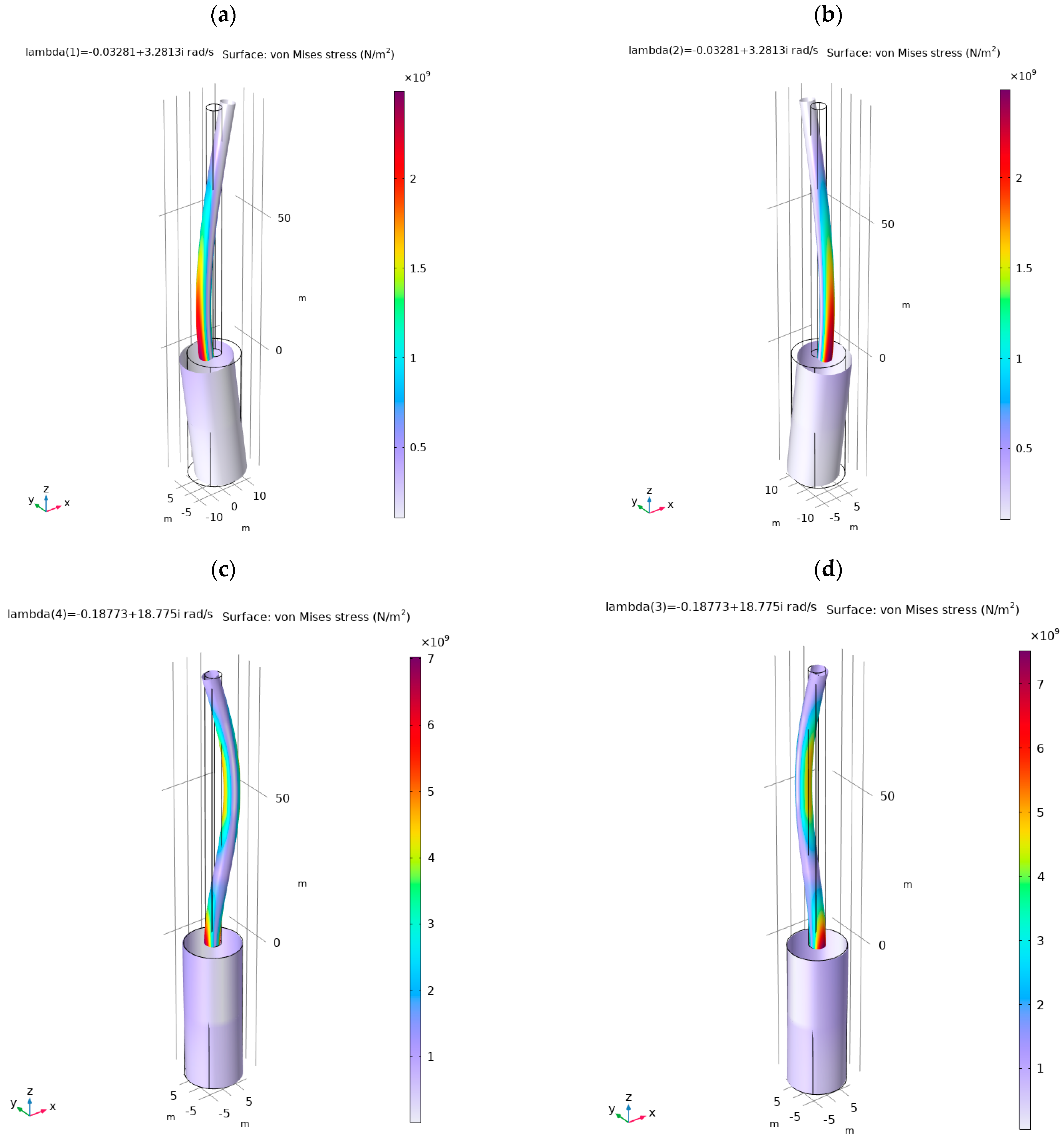
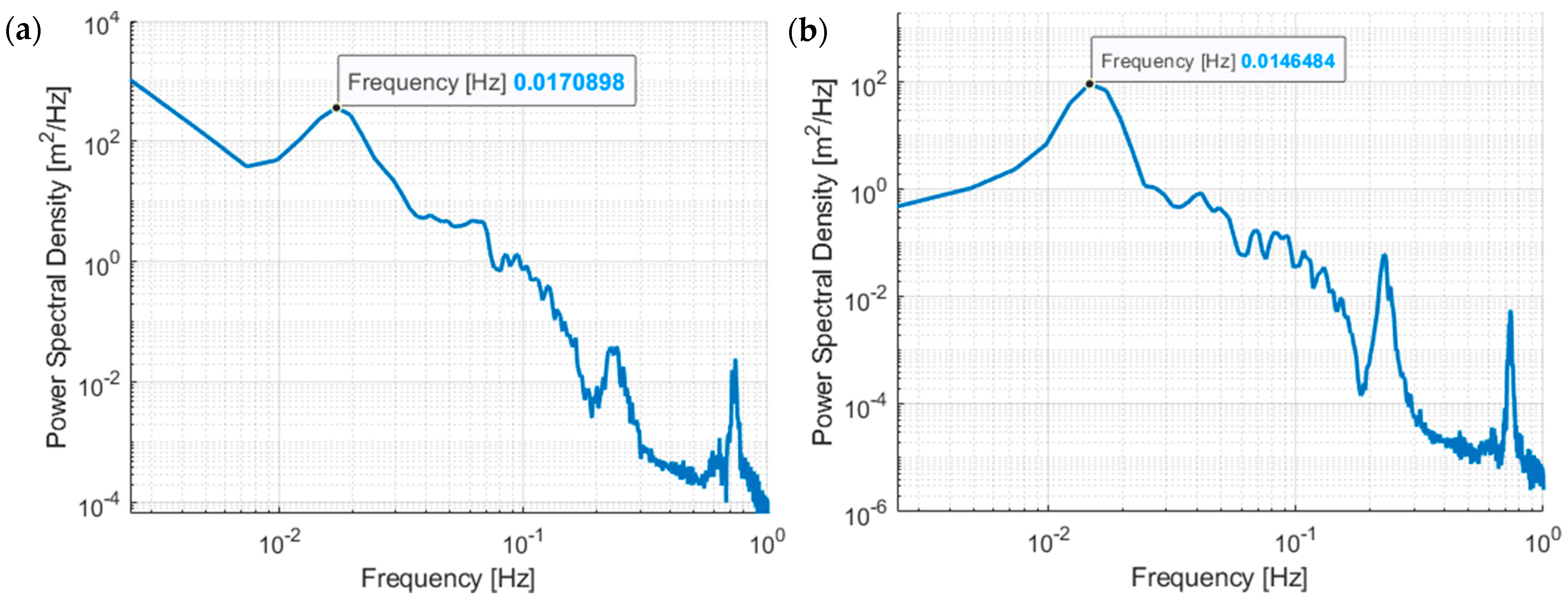
| TLP Surge/Sway | 0.0171/0.0171 Hz | 0.0165/0.0165 Hz | 0.0178/– Hz | ||||
| Tower 1st Fore–aft/Side–side | 0.5222/0.5222 Hz | 0.6311/0.5745 Hz | 0.5000/– Hz | ||||
| Tower 2nd Fore–aft/Side–side | 2.9881/2.9881 Hz | 3.0578/3.1491 Hz | –/– Hz | ||||
| (b) | |||||||
| Models α | OpenFAST | Comsol/MATLAB/Simulink | |||||
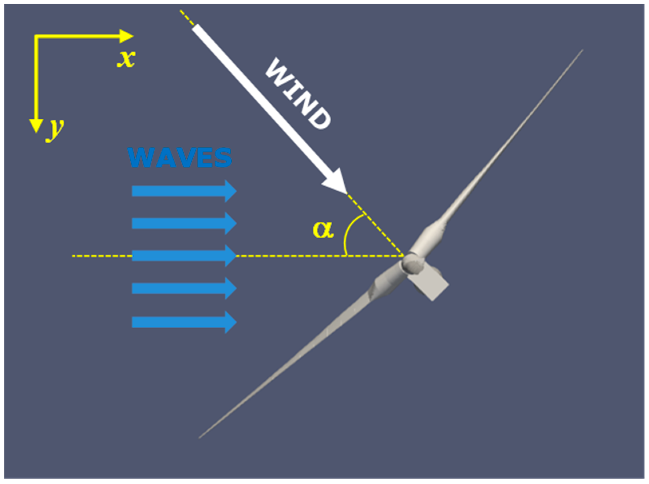
| Index | 0° | 45° | 90° | 0° | 45° | 90° | |
| Along the waves (x) | [m] | 3.0442 | 2.6302 | 2.2095 | 3.0546 | 2.6341 | 2.2393 |
| [m] | 7.9061 | 7.0154 | 6.1960 | 7.8123 | 6.9996 | 5.7403 | |
| [m] | 0.3429 | 0.3931 | 0.5028 | 0.3095 | 0.3921 | 0.5060 | |
| [m] | 1.1976 | 1.2608 | 1.6612 | 1.3190 | 1.5271 | 1.7135 | |
| Transversal (y) | [m] | 0.8452 | 1.8037 | 2.4395 | 0.8606 | 1.8328 | 2.4515 |
| [m] | 2.1009 | 3.9087 | 5.1601 | 2.5073 | 3.7537 | 5.0019 | |
| [m] | 0.1322 | 0.2785 | 0.2462 | 0.1344 | 0.2747 | 0.2494 | |
| [m] | 0.4206 | 0.8675 | 0.5812 | 0.4822 | 0.8986 | 0.5550 | |
| m2 | 10.0 t |
| k2 | 102.7 kN/m |
| c2 | 5.886 kNs/m |
| Fmrnom | 100 kN (160 kN peak force) |
| Fanom1 | 7.1 kN (H-MR-TVAv1) |
| Fanom2 | 14.2 kN (H-MR-TVAv2) |
| Test Cases | No TVA | Passive 20-ton TVA | Passive 10-ton TVA | Semi-Active 10-ton MR-TVA | Hybrid 10-ton H-MR-TVAv1 | Hybrid 10-ton H-MR-TVAv2 | |
|---|---|---|---|---|---|---|---|
| Index | |||||||
| Along the waves | [m] | 0.3095 – | 0.3139 +1.4% | 0.3232 +4.4% | 0.3031 −2.1% | 0.3014 −2.6% | 0.3006 −2.9% |
| [m] | 1.3190 – | 1.2651 −4.1% | 1.2764 −3.2% | 1.1607 −12.0% | 1.1416 −13.5% | 1.1229 −14.9% | |
| [m] | 2.3248 – | 2.9379 +26.4% | 2.0675 −11.1% | 1.9840 −14.7% | 1.8916 −18.6% | ||
| Transversal | [m] | 0.1344 – | 0.1308 −2.7% | 0.1379 +2.6% | 0.1371 +2.0% | 0.1362 +1.3% | 0.1364 +1.5% |
| [m] | 0.4822 – | 0.4689 −2.8% | 0.5131 +6.4% | 0.5039 +4.5% | 0.5007 +3.8% | 0.5006 +3.8% | |
| [m] | 1.0289 – | 0.5691 −44.7% | 0.4826 −53.1% | 0.3972 −61.4% | 0.5315 −48.3% |
| Test Cases | No TVA | Passive 20-ton TVA | Passive 10-ton TVA | Semi- active 10-ton MR-TVA | Hybrid 10-ton H-MR-TVAv1 | Hybrid 10-ton- H-MR-TVAv2 | |
|---|---|---|---|---|---|---|---|
| Index | |||||||
| Along the waves | [m] | 0.3921 – | 0.3905 −0.4% | 0.4098 +4.5% | 0.3937 +0.4% | 0.3921 0.0% | 0.3910 −0.3% |
| [m] | 1.5271 – | 1.4869 −2.6% | 1.5421 +1.0% | 1.4338 −6.1% | 1.4286 −6.5% | 1.4230 −6.8% | |
| [m] | 2.8830 – | 3.3148 +15.0% | 2.3974 −16.8% | 2.3195 −19.6% | 2.2419 −22.2% | ||
| Transversal | [m] | 0.2747 – | 0.2702 −1.6% | 0.2768 +0.8% | 0.2758 +0.4% | 0.2753 +0.2% | 0.2759 +0.4% |
| [m] | 0.8986 – | 0.8792 −2.2% | 0.9374 +4.3% | 0.9090 +1.2% | 0.8964 −0.2% | 0.9316 +3.7% | |
| [m] | 1.7912 – | 0.8344 −53.4% | 0.8110 −54.7% | 0.7312 −59.2% | 0.6979 −61.0% |
| Test Cases | No TVA | Passive 20-ton TVA | Passive 10-ton TVA | Semi- Active 10-ton MR-TVA | Hybrid 10-ton H-MR-TVAv1 | Hybrid 10-ton H-MR-TVAv2 | |
|---|---|---|---|---|---|---|---|
| Index | |||||||
| Along the waves | [m] | 0.5060 – | 0.4984 −1.5% | 0.5249 +3.7% | 0.5124 +1.3% | 0.5109 +1.0% | 0.5097 +0.7% |
| [m] | 1.7135 – | 1.7461 +1.9% | 1.7645 +3.0% | 1.6822 −1.8% | 1.6720 −2.4% | 1.6622 −3.0% | |
| [m] | 3.6999 – | 3.5520 −4.0% | 2.5547 −31.0% | 2.4925 −32.6% | 2.4270 −34.4% | ||
| Transversal | [m] | 0.2494 – | 0.2498 +0.2% | 0.2475 −0.8% | 0.2462 −1.3% | 0.2469 −1.0% | 0.2507 +0.5% |
| [m] | 0.5550 – | 0.5469 −1.5% | 0.5851 +5.4% | 0.5535 −0.3% | 0.5719 +3.1% | 0.6194 +11.6% | |
| [m] | 0.8341 – | 0.7252 −13.1% | 0.4965 −40.5% | 0.4944 −40.7% | 0.7150 −14.3% |
Disclaimer/Publisher’s Note: The statements, opinions and data contained in all publications are solely those of the individual author(s) and contributor(s) and not of MDPI and/or the editor(s). MDPI and/or the editor(s) disclaim responsibility for any injury to people or property resulting from any ideas, methods, instructions or products referred to in the content. |
© 2025 by the authors. Licensee MDPI, Basel, Switzerland. This article is an open access article distributed under the terms and conditions of the Creative Commons Attribution (CC BY) license (https://creativecommons.org/licenses/by/4.0/).
Share and Cite
Martynowicz, P.; Ślimak, P.; Katsaounis, G.M. TLP-Supported NREL 5MW Floating Offshore Wind Turbine Tower Vibration Reduction Under Aligned and Misaligned Wind-Wave Excitations. Energies 2025, 18, 2092. https://doi.org/10.3390/en18082092
Martynowicz P, Ślimak P, Katsaounis GM. TLP-Supported NREL 5MW Floating Offshore Wind Turbine Tower Vibration Reduction Under Aligned and Misaligned Wind-Wave Excitations. Energies. 2025; 18(8):2092. https://doi.org/10.3390/en18082092
Chicago/Turabian StyleMartynowicz, Paweł, Piotr Ślimak, and Georgios M. Katsaounis. 2025. "TLP-Supported NREL 5MW Floating Offshore Wind Turbine Tower Vibration Reduction Under Aligned and Misaligned Wind-Wave Excitations" Energies 18, no. 8: 2092. https://doi.org/10.3390/en18082092
APA StyleMartynowicz, P., Ślimak, P., & Katsaounis, G. M. (2025). TLP-Supported NREL 5MW Floating Offshore Wind Turbine Tower Vibration Reduction Under Aligned and Misaligned Wind-Wave Excitations. Energies, 18(8), 2092. https://doi.org/10.3390/en18082092