Article

Research on Measures to Limit Short-Circuit Current by Changing the Structure of the Power Grid

1
College of Instrumentation and Electrical Engineering, Jilin University, Changchun 130061, China
2
China Electric Power Research Institute, Beijing 100192, China
3
Dandong Jinshan Thermal Power Co., Ltd., Dandong 118000, China
*
Author to whom correspondence should be addressed.
Energies 2025, 18(8), 2098; https://doi.org/10.3390/en18082098
Submission received: 30 March 2025 / Revised: 16 April 2025 / Accepted: 17 April 2025 / Published: 18 April 2025

Abstract

:
This paper addresses the increasingly severe issue of excessive short-circuit currents brought about by the rapid development of large power grids. The working principles of structural changes in the grid as a means of limiting currents are studied, and an impedance matrix is constructed using the additional branch method to analyze the control effects of these limiting measures on short-circuit currents. To explore how to control the level of short-circuit currents in large power grids, this paper provides a detailed analysis of the working principles, advantages, and disadvantages of eight grid structural change measures, including electromagnetic ring network breaking, bus splitting, line interruption, and line coupling. The applicable conditions for each short-circuit-current-limiting measure are established, and specific engineering simulation cases are used to verify their effectiveness in limiting short-circuit currents. The results indicate that this research plays a significant role in controlling short-circuit currents in power systems, maintaining the safe and stable operation of power systems, and improving the structure of power system networks.

1. Introduction

The power system is a crucial infrastructure for the development of the national economy, responsible for providing users with safe, economical, and reliable electricity. With the rapid growth of the national economy and ongoing urbanization, China’s power industry is also developing at a remarkable pace. The continuous expansion of the power grid has led to an increasingly complex transmission and distribution system, and the density of electricity consumption continues to rise. These changes in the power grid inevitably result in an increase in short-circuit current levels, with excessive or nearly excessive short-circuit currents causing a bottleneck for power development in some regions. There is an increasingly stark contradiction between the development of the power grid and the control of short-circuit current levels. In many developed regions, both domestically and internationally, some substations have already experienced short-circuit current levels that exceed the maximum interrupting capacity of circuit breakers, raising concerns about the safe and stable operation of the power grid. Thus, effectively controlling short-circuit current levels while developing the power grid has become a pressing issue that must be addressed by countries worldwide.
For many years, scholars both domestically and internationally have conducted extensive research on how to address the issue of excessive short-circuit currents. In the literature, Eroshenko et al. believe that short-circuit-current-limiting measures are crucial for power systems, as they can reduce damage to electrical equipment and ensure the efficient operation of the power system [1]. Jin et al. believes that short-circuit-current-limiting methods in power grids require comprehensive analysis and selection, taking into account grid planning, design, and operational models, as well as equipment manufacturing and installation [2]. Schlabbach suggests that measures changing the structure of the power grid to limit short-circuit currents may be more cost-effective than replacing equipment and devices [3]. Vorkunov et al. state that separating the low-voltage windings of transformers or connecting current-limiting reactors can effectively limit three-phase short-circuit currents in power transformers [4]. Liu et al. provides a fast and effective method to determine the feasibility of using traction switches to limit short-circuit currents in 3/2 wiring substations, promoting their application in power grids [5]. Han et al. asserts that the limitation of short-circuit currents in the grid can be achieved through the appropriate planning of grid connections and high-impedance facilities, offering two measures to limit asymmetric short-circuit currents [6]. Yuan et al. effectively limited the short-circuit currents in the Northwest power grid using measures such as voltage grading, reactors, bus splits, and high-impedance transformers [7]. Xiong et al. studied the Guangdong power grid and concluded that the limitation of short-circuit currents could be achieved through partitioning the 220 kV grid and connecting small reactors to achieve high-impedance transformations and the grounding of transformer neutral points [8]. Lu et al. points out that short-circuit-limiting technologies can effectively reduce short-circuit currents in the grid and enhance the stability of power systems, although some issues may arise during implementation [9]. Pan et al. replaced side switches with fast switches and disconnected intermediate circuit breakers to effectively limit short-circuit currents in the 500 kV grid of Henan, enhancing grid reliability and laying a foundation for engineering applications [10]. Qi et al. considered three strategies—replacing switches, disconnecting lines, and shutting down generators—to effectively limit short-circuit currents [11]. Zhang et al. argue that fault current limiters (FCLs) can effectively limit short-circuit currents in ultra-high voltage transmission lines without significantly affecting the automatic reclosure overvoltage [12]. Ren and Zhang note that current-limiting reactors can effectively limit short-circuit currents in 500 kV power systems but may increase the transient recovery voltage gradient during circuit breaker fault interruptions [13]. They propose a method for interruption elements that reduces short-circuit currents and improves the calculation speed of grid parameters [14]. Yang et al. state that the Guangdong power grid can effectively limit short-circuit currents through distribution equipment upgrades and power source partitioning measures [15]. Viktorovich et al. also point out that traditional current-limiting devices are insufficient for achieving energy-efficient transmission and distribution systems and call for the development of new devices [16]. Safonov et al. suggest that semiconductor current-limiting devices based on DC choppers can effectively limit excessive short-circuit currents in power systems, being small in size, low in dissipation, and able to efficiently cool without heat sinks [17]. Luo et al. argue that fault current limiters can reduce bus voltage drops and system losses and use a combined weighting coefficient method to select their optimal installation positions [18]. Kui Ma believes that fast switch-type limiters effectively reduce short-circuit currents in 220 kV transmission lines, ensuring system stability and safety [19]. Castro et al. propose a new modeling method that combines superconducting fault current limiters, allowing for accurate simulations of large power grids and comparisons with other methods [20]. The short-circuit-limiting strategy proposed by Yu et al. effectively reduces peak short-circuit currents to below 70%, enhancing the operational stability of distribution networks in industrial and mining enterprises [21]. Han et al. compared and analyzed the advantages and disadvantages of several current-limiting methods, describing the practical applications and development trends of each method [22]. Additionally, under conditions where multiple current-limiting measures are feasible, Sun et al. provide a multi-objective decision theory-based optimization method for combining weights to determine the optimal current-limiting scheme [23].
Currently, research on short-circuit-current-limiting measures, both domestically and internationally, generally categorizes them into traditional and novel measures. Traditional measures are further divided into those that change the grid structure and those that retrofit grid equipment. Subsequently, a more detailed classification based on the current-limiting principles of each measure is conducted, highlighting the similarities among similar measures and the shortcomings in studying the characteristics of dissimilar measures. In current engineering practice, the selection of short-circuit-current-limiting measures is often based on engineering experience rather than a systematic study that investigates the principles, advantages, and disadvantages of various measures, along with specifying the conditions under which each measure is applicable.
Apart from the power grid in the northwest region of China, other areas have established a grid structure with 500 kV as the backbone, 220 kV as the mainline, and 110/66 kV as high-voltage distribution lines. Among these, the issue of excessive short-circuit currents in the 500–220 kV high- and low-voltage electromagnetic ring network is particularly pronounced. This paper focuses on the problem of excessive short-circuit currents in the 500–220 kV high- and low-voltage electromagnetic ring networks within China’s large power grids. It employs an impedance matrix constructed using the additional branch method to analyze the mechanisms and applicable conditions, as well as the advantages and disadvantages, of commonly used measures that alter the grid structure. Furthermore, specific grid examples are provided to show the current-limiting effects of each short-circuit-current-limiting measure.

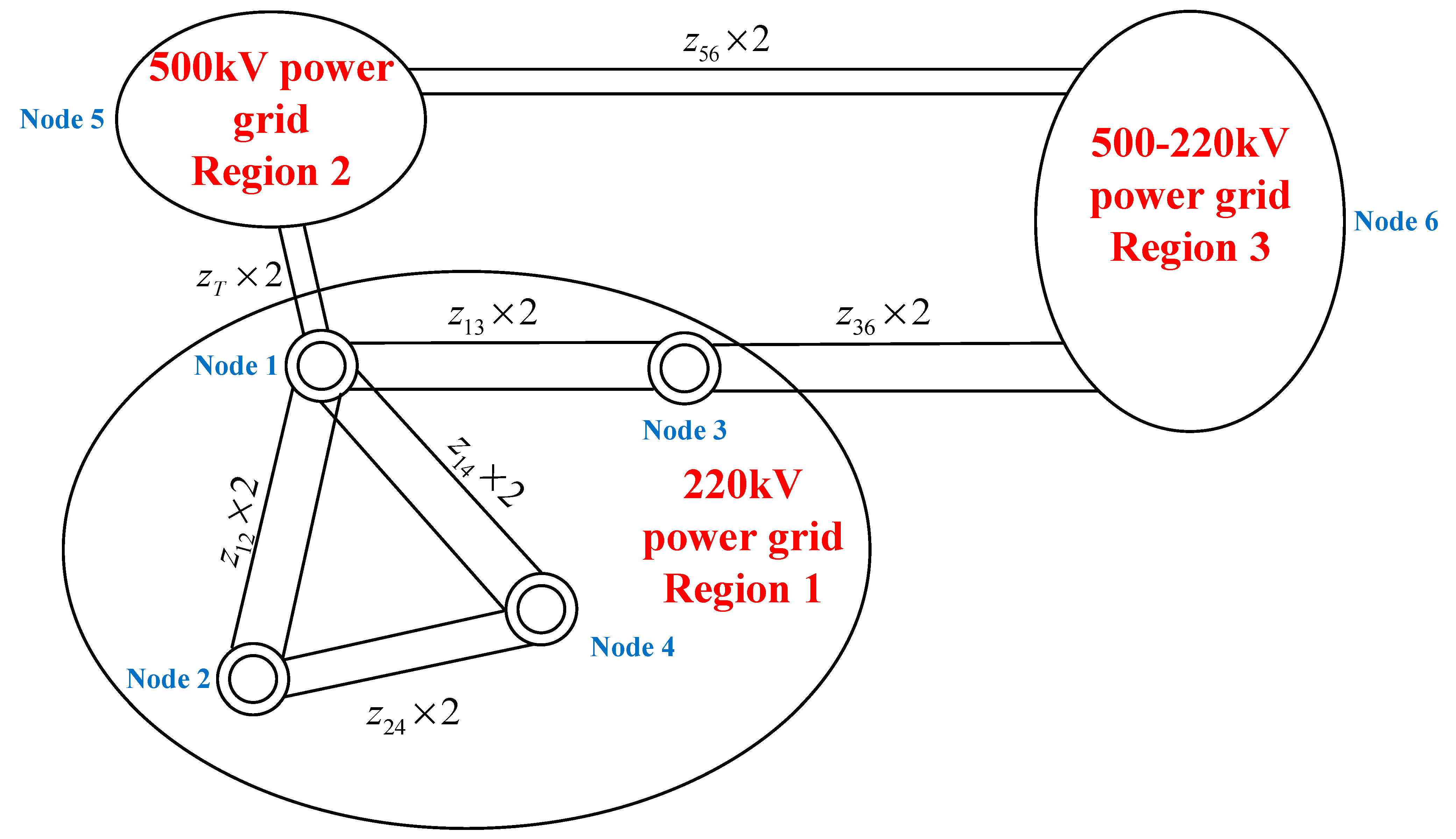
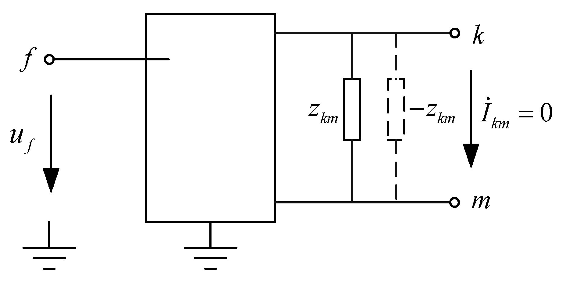
2. Constructing Impedance Matrix Using Additional Branch Method

The power grid can be abstracted as a network structure composed of points and lines. For the calculation of short-circuit currents at each point in the grid, the method typically used is based on impedance matrix calculations. The impedance matrix is the inverse of the admittance matrix; therefore, factors causing changes in the admittance matrix will similarly lead to changes in the impedance matrix, which in turn affects the short-circuit currents at the relevant points. There are generally two factors that cause changes in the impedance matrix of the power grid: one is a change in the topology of the power system, and the other is a change in the parameters of the power system. Relating this to the issue of short-circuit current control, short-circuit-current-limiting measures can be divided into two categories based on their mode of action: altering the structure of the power system and retrofitting the equipment of the power system. Changing the structure of the power system corresponds to the first factor, which causes a change in the impedance matrix, whereas retrofitting the equipment corresponds to the second factor, which leads to changes in the impedance matrix.
As long as the relevant parameters of the power grid remain unchanged, the system’s admittance matrix is determined and remains constant, and it can be easily written directly from the admittance of each branch in the network. However, the impedance matrix, as the inverse of the admittance matrix, has a special physical significance: the diagonal elements Z i i are referred to as the self-impedance of the i nodes, numerically equal to the voltage at node i when a unit current is injected into node i while all other nodes are open-circuited. Therefore, Z i i must be a non-zero finite value. The off-diagonal elements Z i j are referred to as the mutual impedance between nodes i and j , numerically equal to the voltage at node j when a unit current is injected into node i with all other nodes being open-circuited. Since there is electromagnetic coupling between all nodes in the power network, whether they are connected or not, the voltage at node j cannot be zero. As long as there is current injected into node i , all nodes in the grid must have voltage; thus, the impedance matrix is a full matrix.
Calculating the impedance matrix is a prerequisite for calculating short-circuit currents. Currently, there are two commonly used methods for calculating the impedance matrix. The first is to directly write out the power grid’s admittance matrix Y , leading to Z = Y 1 ; the second is to select an initial grounding node and use the additional branch method to gradually expand and correct the impedance matrix.
The steps to construct the impedance matrix using the additional method are as follows:
Assume the number of nodes in the original power grid is m , and let the impedance matrix be
Z N = Z 11 Z 12 Z 1 i Z 1 m Z 21 Z 22 Z 2 i Z 2 m     Z i 1 Z i 2 Z i i Z i m     Z m 1 Z m 2 Z m i Z m m
A new node j is added to the original power network at node i , and the branch impedance between the two points is Z i j . At this point, the original impedance matrix will increase in order by one.
After the addition of node j and branch i j , let the new impedance matrix be
Z N = Z 11 Z 12 Z 1 i Z 1 m Z 1 j Z 21 Z 22 Z 2 i Z 2 m Z 2 j     Z i 1 Z i 2 Z i i Z i m Z i j     Z m 1 Z m 2 Z m i Z m m Z m j Z j 1 Z j 2 Z j i Z j m Z j j
There is
Z p q = Z p q   ( 0 p ,   q m ) Z k j = Z j k = Z k i   ( 0 k m ) Z j j = Z i i + z i j
After adding the “tree branch”, the elements of the original impedance matrix remain unchanged, with only the addition of a new row and a new column for the last elements.
If the number of nodes in the original power network remains unchanged, and a new branch with impedance Z i j is added only between points i and j , then there is
Z k l = Z k l Z L k Z L l Z L L Z L L = Z j j + Z i i 2 Z i j + z i j
In the equation, Z k l is the element of the transformed impedance matrix, and Z k l is the element of the original impedance matrix, Z L k = Z k i Z k j , Z L l = Z l i Z l j , 0 k ,   l m .
That is, the computational effort when adding a “chain branch” is greater, as every element of the original impedance matrix needs to be corrected. Therefore, when constructing the impedance matrix after a change in the power grid structure, one should first add the “chain branches” to complete the correction of all matrix elements as much as possible when the order is lower and then finally add the “tree branches” to increase the order of the matrix.
The impedance matrix plays an important role in power system analysis; the power system usually consists of many components, and the use of impedance matrix can simplify the complex relationships among these components into mathematical expressions, making the analysis of the system behavior more intuitive and systematic. Through the use of the impedance matrix, it is also possible to quantitatively compare different short-circuit-current-limiting measures; when changes occur in the power system, the impedance matrix can better assess the effectiveness of different short-circuit-current-limiting methods and also reveal the impact of network structure changes on system performance.

3. Current-Limiting Measures for Changing Power Grid Structures

To address the issue of excessive short-circuit current, one option is to replace circuit breakers with ones that have a larger interrupting capacity. However, due to the technical conditions for manufacturing circuit breakers and the engineering conditions for connecting the breakers to the power grid, there is a limit to the maximum interrupting capacity for circuit breakers at each voltage level. This limiting value represents the upper limit of the short-circuit current that should be controlled at that voltage level. The upper limit of short-circuit current for each voltage level is shown in Table 1.
For this paper, we conducted research on current-limiting measures related to changes in power grid structures. Based on the principles of action of each measure, they are divided into three categories: significant changes in power grid structure, partial changes in power grid structure, and measures for switching power grid lines.

3.1. Significant Changes in Power Grid Structure

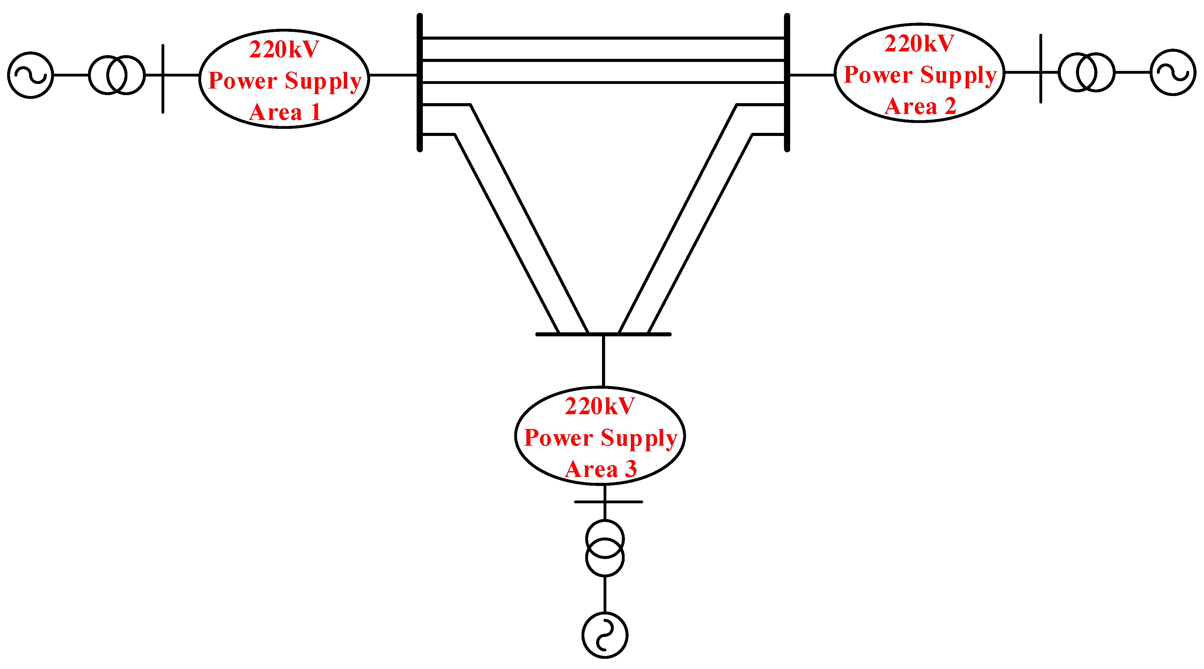
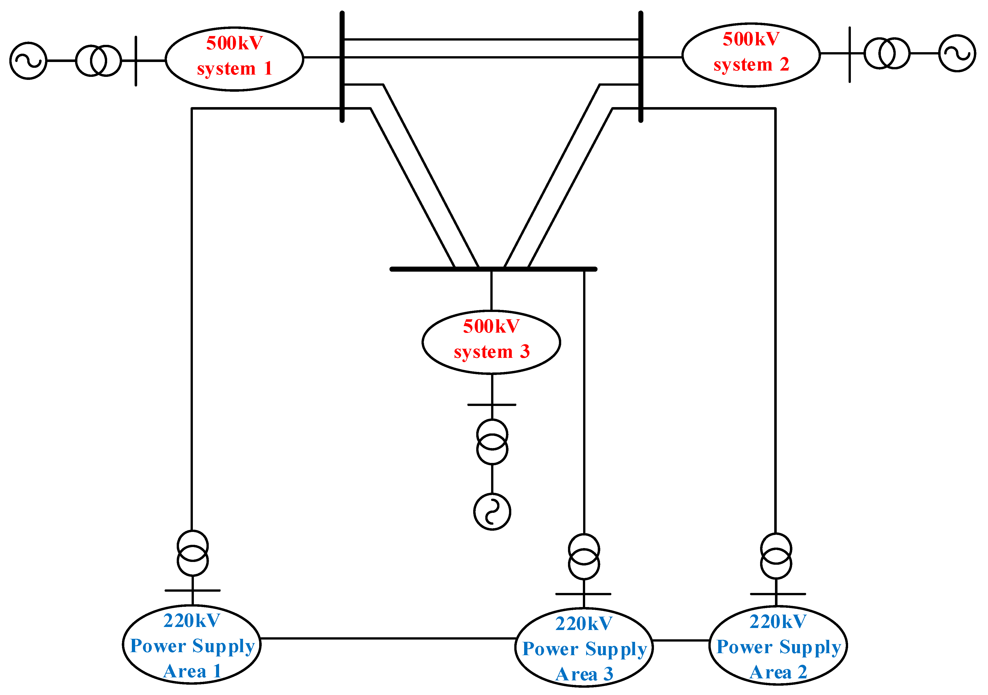
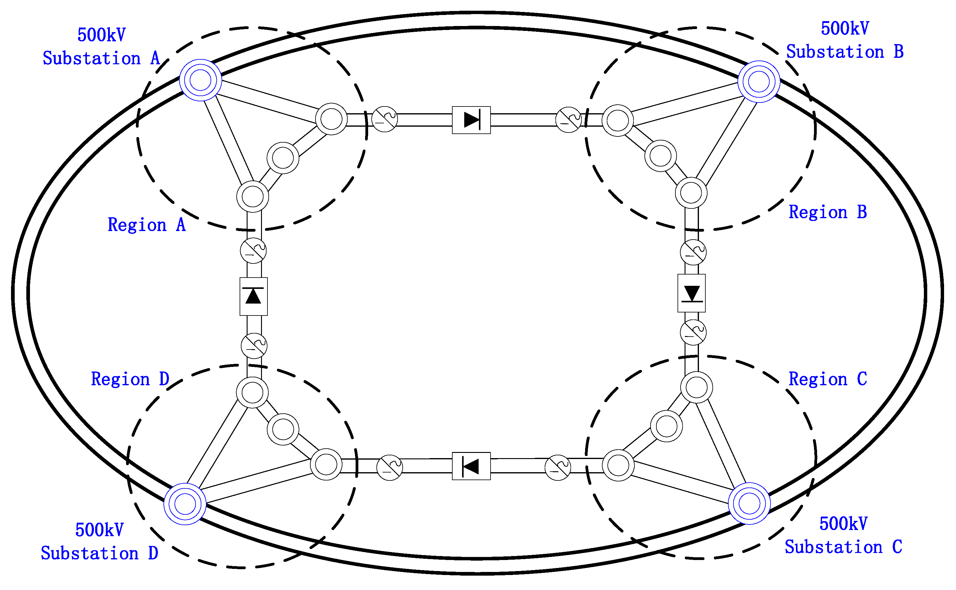
3.1.1. Power Grid Layering and Zoning

Since the reform and opening-up, the power industry in China has been developing at a rapid pace. As the development level of low-voltage level grids has increased and their structures have become more compact, the electrical distance within the grid has gradually decreased, leading to an ongoing rise in short-circuit current levels. Consequently, the contradiction between the development of grid structures and the increase in short-circuit current levels has become increasingly pronounced.
The process of layering and zoning a power grid consists of two steps: the first step involves dividing the power system into several hierarchical levels from top to bottom according to voltage levels and transmission/distribution capabilities, which is referred to as layering. The second step involves dividing a grid with the same voltage level into several regions based on the balance of supply and demand for electrical energy within each region; the regions are interconnected through zonal linking lines to ensure power supply reliability, which is referred to as zoning. Long-term engineering research has shown that developing higher-voltage-level grids, followed by operating lower-voltage-level grids—which expose issues with exceeding short-circuit current limits in a zoned manner—is a fundamental measure in resolving the problem of excessive short-circuit currents and is an inevitable trend in the long-term development of the power grid.
A layering and zoning operation can only be implemented when the grid topology is sufficiently robust. Diagrams of grid layering and zoning are illustrated in Figure 1 and Figure 2. In Figure 1, the 220 kV grid has developed over time into a structure with high reliability, a strong network, and intricate connections; however, the key substations in this grid are experiencing issues with excessive short-circuit currents.
By introducing the 500 kV power grid to undertake transmission tasks and implementing a planned zonal operation for the various 220 kV supply areas while retaining only the inter-zone connecting lines, the degree of compactness of the connecting lines between the 220 kV regions is reduced. This increases the electrical distance and lowers the short-circuit current levels to some extent. This measure facilitates the transformation of the 220 kV grid from a transmission grid to a distribution grid, which not only meets the long-term development needs of the power grid but also fundamentally resolves the issue of excessive short-circuit currents in the 220 kV system. The schematic diagram after layering and zoning is shown in Figure 2.

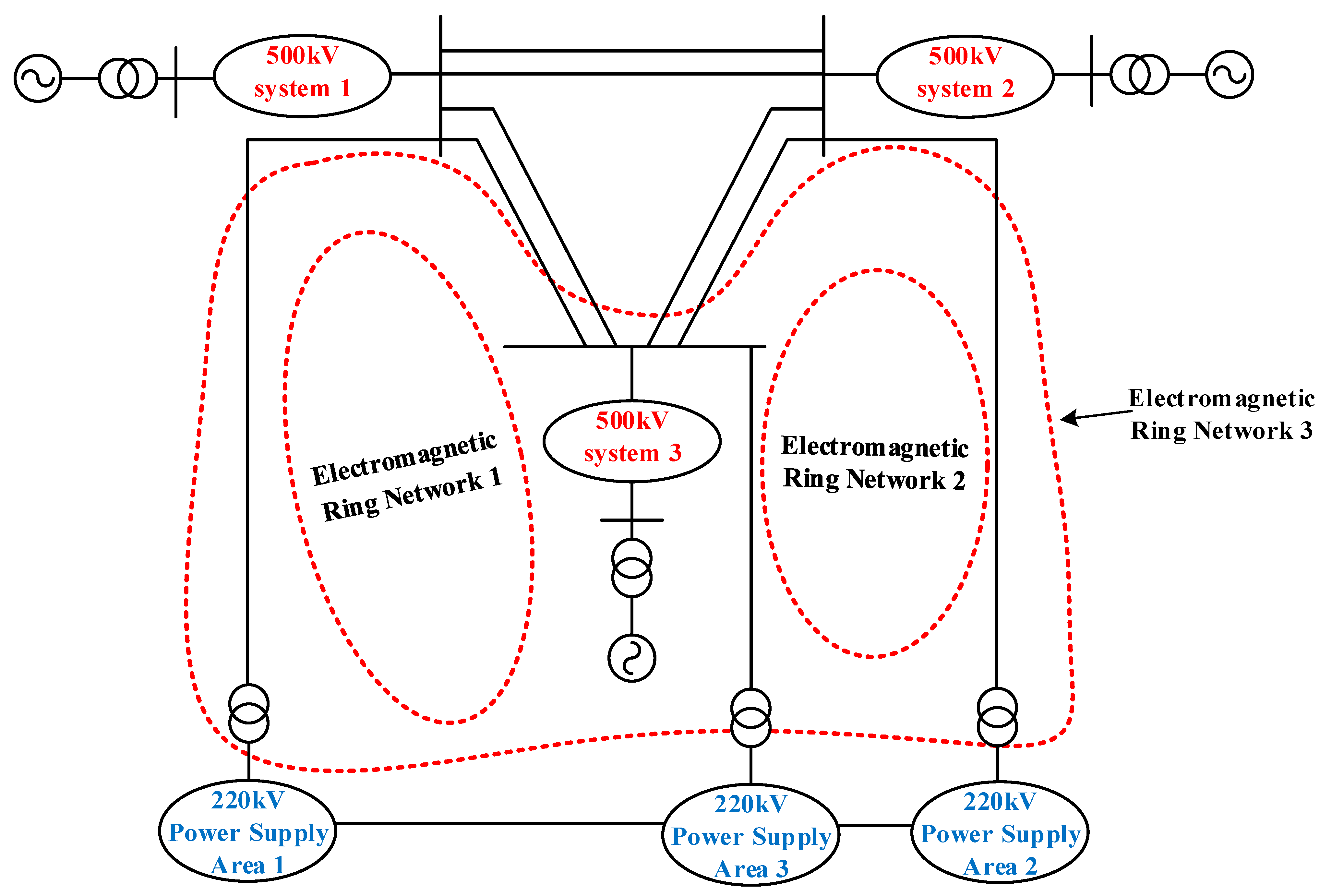
3.1.2. Electromagnetic Ring Network Breaking

An electromagnetic ring network refers to a power network at different voltage levels that is formed through the magnetic circuit of transformers or connections between electrical and magnetic circuits. Therefore, the existence of an electromagnetic ring network often relies on interconnecting transformers between two voltage levels in the power grid. As noted in Section 3.1.1, the development of a higher-level power grid is a fundamental method and inevitable trend in resolving the issue of excessive short-circuit currents in current-voltage-level networks. If the newly established higher-level grid is taking shape while the lower-level grid has not yet been zonally operated, then there will be a significant number of electromagnetic ring networks within the entire power system.
Taking the schematic diagram shown in Figure 3 as an example, after introducing the 500 kV power grid, the 220 kV areas may not yet satisfy the balance of power supply and demand within their regions. Therefore, some inter-zone connecting lines are retained to ensure the reliability of the power supply. At this point, through the connection of the interconnecting transformers between levels, an electromagnetic ring network with high and low voltage exists in the power system: 500 kV substation 1–500/220 kV transformer 1–220 kV substation 1–220 kV substation 2–220/500 kV transformer 2–500 kV substation 2–500 kV substation 1. The schematic diagram of the electromagnetic ring network in the power grid shown in Figure 2 is illustrated in Figure 3.
Although the existence of electromagnetic ring networks is beneficial for power transmission and ensures the reliability of power supply in the early stages of developing a higher-level power grid, the drawbacks of these networks are gradually emerging as high-voltage networks continue to evolve. These drawbacks mainly include issues related to transient stability, dynamic stability, thermal stability, short-circuit current problems, and the complexity of configuring protection and safety stability control measures. Among these, the short-circuit current issue is the focus of this study. Under the conditions of an electromagnetic ring network, the large-scale centralized operation of power sources, the strengthening of the grid structure, and a continuous increase in load density accelerate a decrease in the system’s short-circuit impedance, thus exacerbating the contradiction between electromagnetic ring networks and short-circuit currents. Therefore, breaking the ring in an electromagnetic ring network is an effective method of limiting short-circuit currents, and the most direct way to achieve this is to open the ring at the interconnecting lines of lower voltage levels.
To further illustrate the current-limiting effect of breaking the electromagnetic ring network, a simplified model of the 500–220 kV power grid is established, as shown in Figure 4.
The diagram consists of three regions, with Region 1 being the main research area of this study. The other two regions are considered as two infinite systems, meaning that changes in the structure and parameters of Region 1 do not affect the voltage and power of the other two regions, allowing further simplification to two nodes. Z T represents the positive-sequence equivalent impedance of the 500/220 kV transformer between Region 1 and Region 2. It is assumed that current-limiting measures are implemented for Node 1, with the original impedance matrix designated as Z , the original short-circuit current at Node 1 designated as I , and the pre-fault voltage set to 1.
To break the electromagnetic ring network, the double circuit line between Node 1 and Node 3 is disconnected. Based on the content of Section 2, the transformation of the impedance matrix is carried out in two steps, as follows:
(1)
Disconnect Line 1 between Node 1 and Node 3.
Introduce a “chain branch” by adding a branch with an impedance of z 13 between the two points. The elements of the impedance matrix are updated as follows:
Z 11 = Z 11 Z L 1 2 Z L L = Z 11 Z 11 Z 13 2 Z 33 + Z 11 2 Z 13 z 13 Z 13 = Z 13 Z L 1 Z L 3 Z L L = Z 13 ( Z 11 Z 13 ) ( Z 13 Z 33 ) Z 33 + Z 11 2 Z 13 z 13 Z 33 = Z 33 Z L 3 2 Z L L = Z 33 Z 13 Z 33 2 Z 33 + Z 11 2 Z 13 z 13
(2)
Disconnect Line 2 between Node 1 and Node 3.
Introduce another “chain branch” by adding a branch with an impedance of z 13 between the two points. The elements of the impedance matrix are updated as follows:
Z 11 = Z 11 ( Z L 1 ) 2 Z L L = Z 11 Z 11 Z 13 2 Z 33 + Z 11 2 Z 13 z 13
Then, the change in short-circuit current at Node 1 is
Δ I = 1 Z 11 1 Z 11 = 2 ( Z 11 Z 13 ) 2 Z 11 ( 2 Z 13 2 2 Z 11 Z 33 + Z 11 z 13 )
The effect of unlooping the electromagnetic ring network on short-circuit current limitation is influenced by the values of the elements in the original impedance matrix related to the endpoints of the unlooping, as well as the impedance of the disconnected line.
Breaking the high-voltage and low-voltage electromagnetic loops can weaken the network structure of the low voltage level, reduce the current path in the event of a short circuit, and control the short-circuit current of the low voltage level. Generally, only power grids with a strong structure will generate an electromagnetic ring network after long-term development, which will lead to the problem of the short-circuit current exceeding the standard, while electromagnetic ring networks do not exist in weaker power grids and the level of the short-circuit current is not high. Therefore, electromagnetic loop unlooping is seldom used in weaker grids.

3.2. Partial Changes in Power Grid Structure

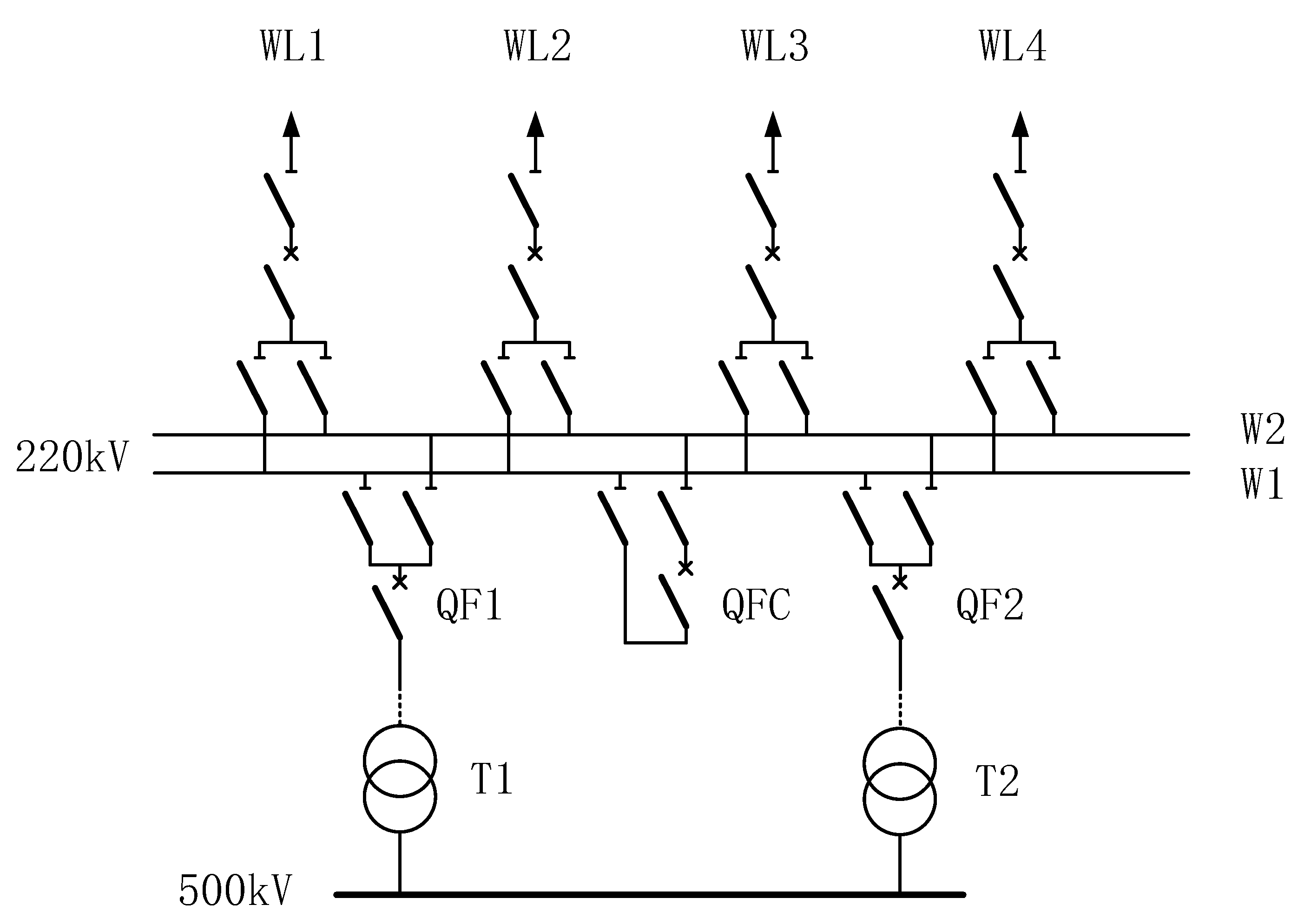
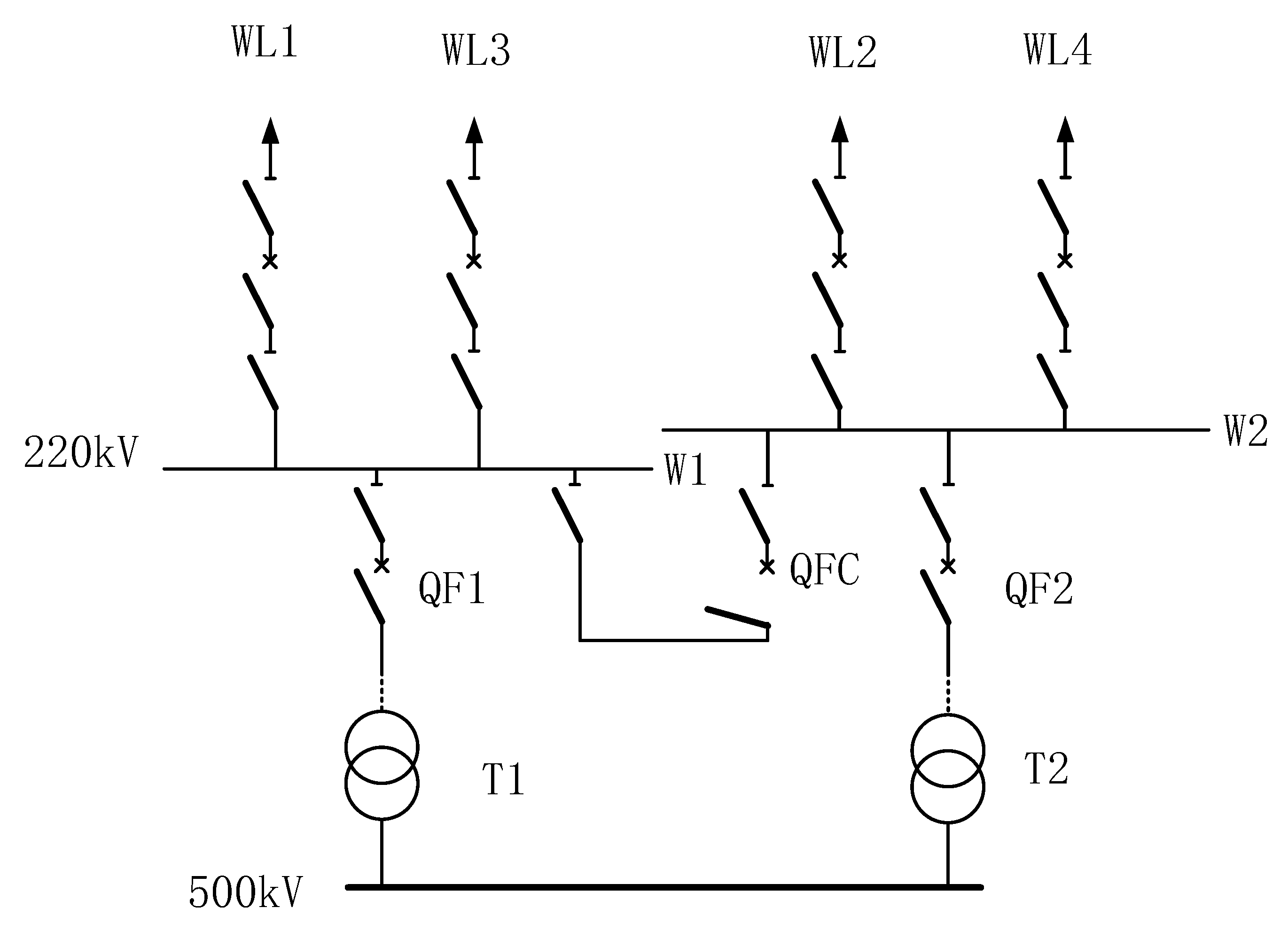
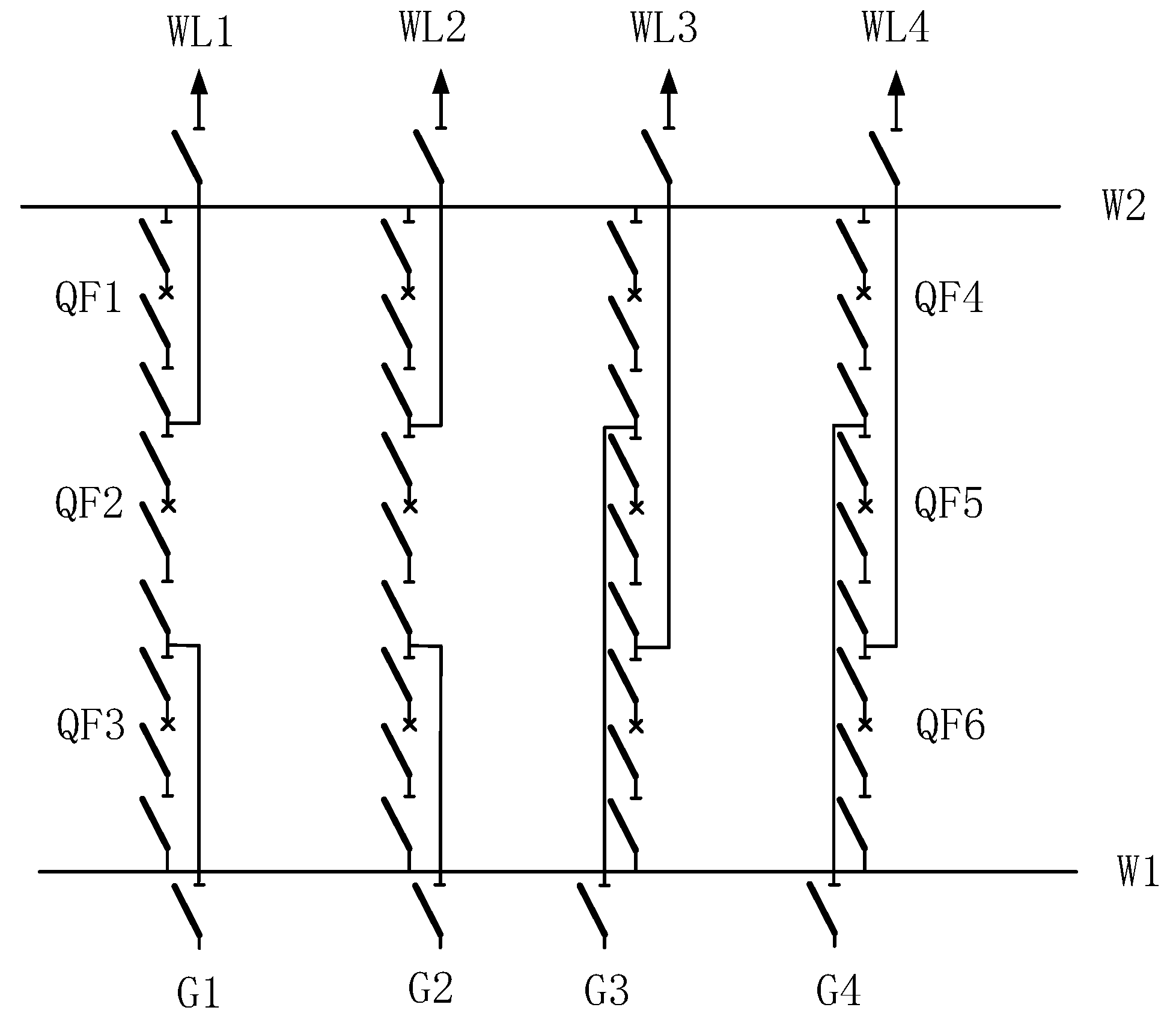
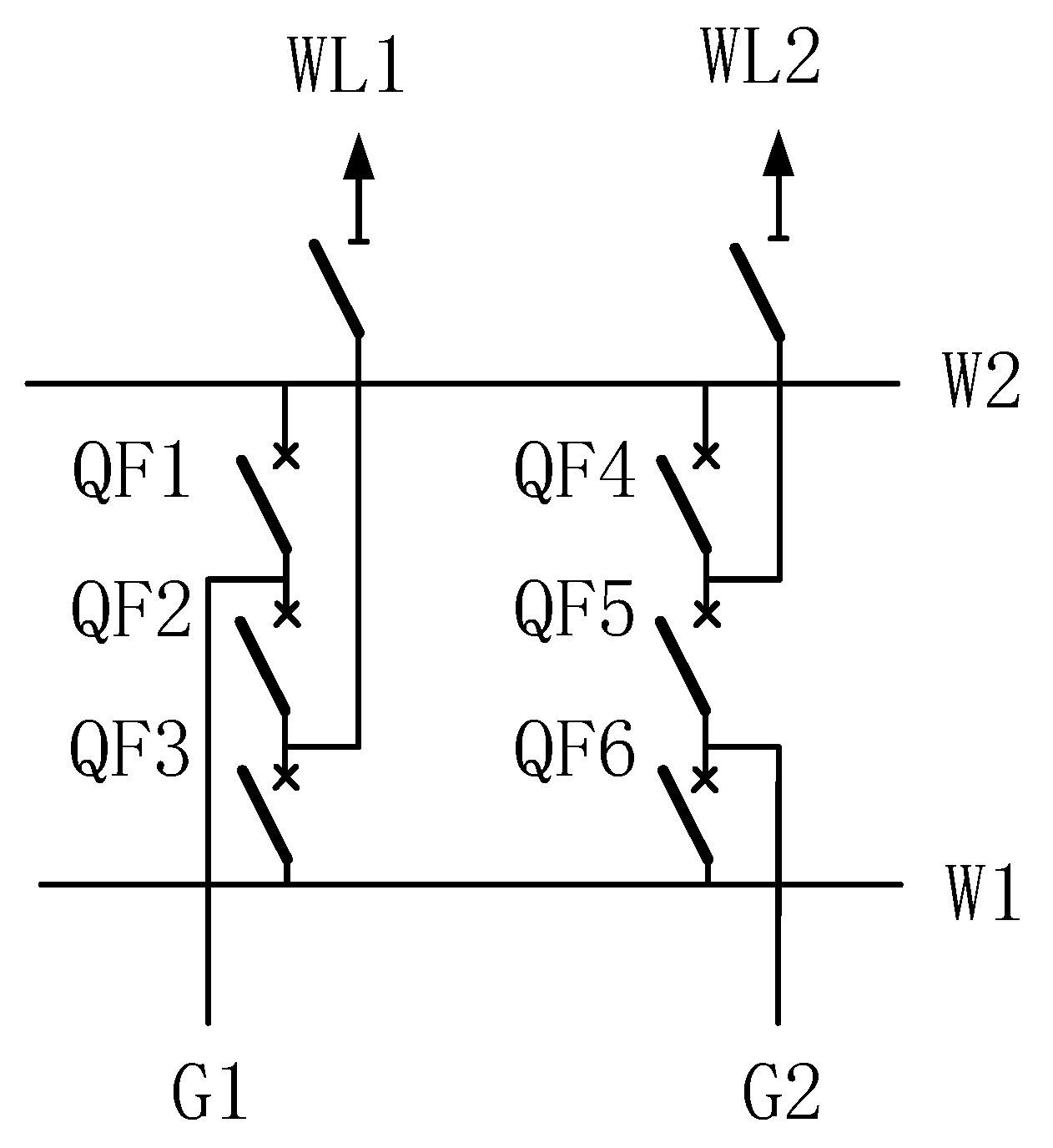
3.2.1. Bus Splitting

Due to its operational convenience, low cost, and significant effectiveness, bus splitting is a commonly used measure to limit short-circuit current both domestically and internationally. Currently, much of China’s power grid is experiencing increasingly closer 220 kV network configurations, gradually entering the final stages of development. Before the large-scale completion of the 500 kV grid and the division of the 200 kV network, the short-circuit current in the 200 kV grid will remain at a high level. In many regions, the exceedance of short-circuit current in the 220 kV network has become a major issue faced by power projects in those areas. Bus splitting is an important method that can effectively address this problem. Most 220 kV substations in China adopt a double-bus or double-bus segmented wiring scheme. Figure 5 shows a typical double-bus connection format. The two sets of buses in a double-bus system serve as backups for each other, with each outgoing line equipped with a circuit breaker and two sets of isolating switches, each connected to one of the two buses. The two buses are interconnected through a bus-coupling circuit breaker (QFC). Compared to single-bus connections, double-bus connections offer advantages such as a more reliable power supply, flexible dispatching, and ease of expansion. Despite the relatively higher investment, the reliability of the power supply is significantly improved, meaning that the double-bus configuration is widely used in the 220 kV network. The double-busbar wiring structure is shown in Figure 5.
As shown in Figure 5, the 220 kV bus receives electrical energy from the 500 kV voltage level through two transformers, T1 and T2. When the system is functioning normally, one bus is energized while the other is in a standby state. When the energized bus encounters a fault, all outgoing lines from that bus are transferred to the standby bus through switching operations, ensuring that the system does not lose power. In this configuration, assuming that bus W1 is the energized bus and W2 is the standby bus, to ensure the power supply for the four outgoing lines WL1, WL2, WL3, and WL4, all four outgoing lines and both transformers need to be connected to bus W1. As a result, the electrical distance between this bus and other electrical components is relatively short, leading to a lower equivalent impedance, which poses a risk of exceeding short-circuit current levels. If the two buses are operated in a split configuration, then the issue of exceeding short-circuit current can be resolved: by disconnecting the bus-coupling circuit breaker (QFC), the outgoing lines WL2 and WL4 can be switched to bus W2 via isolating switches, and the transformer T2 branch can also be switched to bus W2, while the outgoing lines WL1 and WL3, along with the transformer branch T1, remain on bus W1. At this point, the original double-bus configuration has been split into two single-bus structures under the same 500 kV substation, each handling half of the original load, which increases the system impedance of the lower-level grid and significantly reduces the short-circuit current of the original bus. The wiring after bus splitting is shown in Figure 6.
However, bus splitting weakens the electrical connections of the system, lacks the flexibility and reliability advantages of the dual-busbar structure, and may also cause uneven power supply and load distribution due to issues with the number of outgoing lines and transformers. An imbalance that occurs where some buses may carry too much load while others appear idle will affect the healthy operation of the system. Therefore, when designing bus splitting, the load should be predicted, and the load of each bus should be reasonably arranged to ensure that the load is evenly distributed. In addition, load monitoring and assessment can be carried out periodically, and corresponding adjustments can be made according to the latest data.

3.2.2. Dynamic Opening and Closing Circuit Breaker

Dynamic opening and closing circuit breakers limit short-circuit current through the installation of a complete monitoring and control system. The basic principle is as follows: the control system of the short-circuit-current-limiting device collects relevant electrical parameters to determine whether a fault has occurred in the power grid or whether the fault has been cleared. When a fault is detected in the power grid, a control signal is sent to the relevant circuit breakers, which have been predetermined through analysis and calculation, to open and interrupt the circuit. This dynamic adjustment of the grid structure during the fault period increases the system impedance, achieving the goal of reducing the short-circuit current after the fault. After the fault is cleared, the relevant circuit breakers are reclosed, restoring the system to its traditional post-fault grid structure.
The main operational sequence of the dynamic opening and closing circuit breaker for limiting short-circuit current is shown in Figure 7.
This measure requires the close coordination of the operational timing between the relevant circuit breakers involved in the dynamic adjustment of the grid structure and the existing circuit breakers that should operate after the fault. The time taken from the occurrence of the fault to the separation of the contacts of the existing circuit breaker includes the relay protection operation time t R e l a y and the mechanical tripping time t O p e n of the existing circuit breaker. The time taken from the occurrence of the fault to the opening and closing of the circuit breakers involved in the dynamic adjustment of the grid structure includes the control system operation time t C t r and the opening and closing time t B r e a k of the circuit breakers involved in the dynamic adjustment. To meet the requirement for limiting the opening current of the existing circuit breakers that should operate after the fault, it is necessary to satisfy the following conditions:
t C t r + t B r e a k t Re l a y + t O p e n
This means that the circuit breakers involved in the dynamic adjustment of the grid structure must complete their opening before the contacts of the existing circuit breakers that should operate after the fault are separated, thereby limiting the opening current of the existing circuit breakers. There are two methods to satisfy the above timing requirements:
Method 1: Keep the existing relay protection operation time and the circuit breaker tripping time unchanged, while shortening the control system operation time and the opening time of the circuit breakers involved in the dynamic adjustment of the grid structure. Achieving this requires the use of fast fault identification and high-speed circuit breakers.
Method 2: Set the opening time of the circuit breakers involved in the dynamic adjustment of the grid structure to be the same as that of the existing circuit breakers after the fault, increasing the protection relay operating time after the fault. After a fault occurs, the control system first sends a tripping command to the circuit breakers involved in the dynamic adjustment, and, after a delay, the relay protection device sends a tripping command to the existing circuit breakers.
Both methods can achieve timing coordination between the circuit breakers involved in the dynamic adjustment of the grid structure and the existing circuit breakers that should operate after the fault, thereby limiting the opening current of the existing circuit breakers. Method 1 does not affect the existing protection and breaker operation, allowing for the rapid limitation of short-circuit current, but requires the use of high-speed circuit breakers to achieve timing coordination. Method 2 requires coordination between the control system and relay protection, avoiding the need for high-speed circuit breakers, but may increase the fault duration, having a greater impact on the system.
The advantages of a dynamic opening and closing circuit breaker are as follows: It effectively reduces the level of short-circuit current during faults and restores the original grid structure after fault clearance, with no impact during normal operation. It offers wide practicality with different circuit breaker placements for adjusting the grid structure based on various substation configurations and fault points. It prevents the decline in power supply reliability and transmission capacity that can occur with conventional grid adjustments and operating methods. It avoids the increased system losses and decreased stability associated with the use of high-impedance devices.
The disadvantages of a dynamic opening and closing circuit breaker are as follows: Regarding the timing coordination between circuit breakers involved in grid structure adjustment and existing circuit breakers, Method 1 faces issues with immature technology, complex manufacturing, high costs, and challenges in effective application at high voltage levels. Method 2 may inadvertently extend the fault duration, causing more significant impacts on the system. It also requires prior system analysis and calculations to determine appropriate circuit breaker placements for various operating modes of the grid to enable dynamic adjustments during faults. If a very weak system arises after grid structure adjustment, this may lead to decreased accuracy in distance protection action boundaries, affecting the selectivity of protective actions.

3.3. Measures for Switching Power Grid Lines

3.3.1. Line Interruption

Breaking the circuit is a relatively common measure to address the issue of excessive short-circuit current due to its simplicity and the fact that no new equipment is required. In areas with a dense grid structure, disconnecting lines with smaller power flow but significant contributions to short-circuit current helps to increase the electrical distance in that area, thereby limiting short-circuit current. According to the principle of constructing the impedance matrix using the additional branch method, if we consider the line between nodes k and m with an impedance of z k m , it can be equivalently represented by adding a parallel “chain branch” with an impedance of z k m between nodes k and m . Let the original impedance matrix be Z , and assume the pre-fault voltage is 1. A schematic diagram of the broken line is shown in Figure 8.
The short-circuit impedance of the disconnected endpoint k is
Z k k = Z k k Z k k Z k m 2 Z m m + Z k k 2 Z k m z k m
The change in short-circuit current of point k is
Δ I = 1 Z k k 1 Z k k = 1 Z k k ( Z m m + Z k k 2 Z k m z k m ) ( Z m m + Z k k 2 Z k m z k m ) Z k k Z k k Z k m 2
The short-circuit impedance of any point f in the network is
Z f f = Z f f ( Z f k Z f m ) 2 Z k k + Z m m 2 Z k m z k m
The change in short-circuit current of point f is
Δ I = 1 Z f f 1 Z f f = 1 Z f f ( Z m m + Z k k 2 Z k m z k m ) ( Z m m + Z k k 2 Z k m z k m ) Z f f Z f k Z f m 2
Line interruption lowers the short-circuit current, but it also reduces the reliability of the system and the utilization rate of equipment, leading to a waste of grid resources. With constant load conditions, extensive circuit disconnections can easily lead to issues such as line overload. For some grid structures that are relatively weak, there is an increased risk of transient or static instability under the “N − 1” principle. While breaking the circuit is more economical compared to developing a higher-voltage-level grid, reconfiguring electromagnetic rings, or implementing replacement or upgrade measures for electrical equipment, it results in a loss of some safety for the grid and is considered a temporary measure.

3.3.2. Adopting Direct Current Transmission

Although the partitioned operation of the power grid can effectively reduce the level of short-circuit current, it can weaken the power support capability between partitions. When two partitions are interconnected directly through AC tie lines, the uncontrollability of power may expand the scope of incidents, significantly increasing the short-circuit capacity of the systems on both sides of the partition and sometimes even exceeding the breaking capacity of the existing circuit breakers. In contrast, flexible direct current (DC) transmission based on voltage source converters can achieve instantaneous decoupled control of active and reactive power, with a compact structure and small footprint, making it easy to form multi-terminal DC systems. Moreover, flexible DC transmission technology can provide emergency support for both active and reactive power, allowing for rapid decoupled control of these powers. It can flexibly operate across four quadrants of active and reactive power without the need for reactive compensation devices, and it can even provide reactive support to the system as needed, offering unique technical advantages in improving system stability and transmission capacity. If two independent partitions are interconnected using flexible DC or “back-to-back” DC networks, this will not increase the short-circuit current. Additionally, because flexible DC converter stations occupy less space, they are suitable for application in urban power grids. Therefore, the DC devices used for interconnection between city grid partitions should ideally utilize “back-to-back” flexible DC devices.
By using flexible DC devices to isolate the two partitions, the flow direction and magnitude between the partitions can be flexibly adjusted without increasing the short-circuit current, while also appropriately compensating for dynamic reactive power, thus enhancing the safety, stability, and reliability of power supply in the grid. In a flexible interconnection setup, the two interconnected partitions are isolated by flexible power electronic devices, which can prevent a fault in one partition from affecting the other. Moreover, the power transmitted over the tie line can be controlled through the flexible power electronic devices. For connected partitions after flexible interconnection, the connection points of the devices to the partitions are equivalent to adding a dynamic reactive power source, which can enhance transient voltage stability in the grid. The converter stations at both ends of the flexible DC are independently controlled, without the need for communication between stations, allowing for flexible and varied control methods to adapt to multiple operating conditions. Flexible DC has a rapid power flow reversal capability, facilitating reverse power support. Furthermore, flexible DC can serve as a “black start” power source for the system, enhancing the recovery capability.
Currently, large power grids generally adopt a structure of 500 kV double-ring networks and 220 kV partitions. By using flexible DC devices to interconnect two or more of these partitions, it is possible to achieve a flexible closed-loop connection form with a 500 kV double-ring network power supply and 220 kV cross-supply between partitions, as shown in Figure 9.
By using flexible DC devices to interconnect the 220 kV power grid zones, the risks of large short-circuit currents and 500/220 kV electromagnetic ring networks faced by conventional AC interconnection lines can be overcome. Adopting flexible DC to partition the power grid can improve the safety and reliability of the 220 kV interconnected power grid.

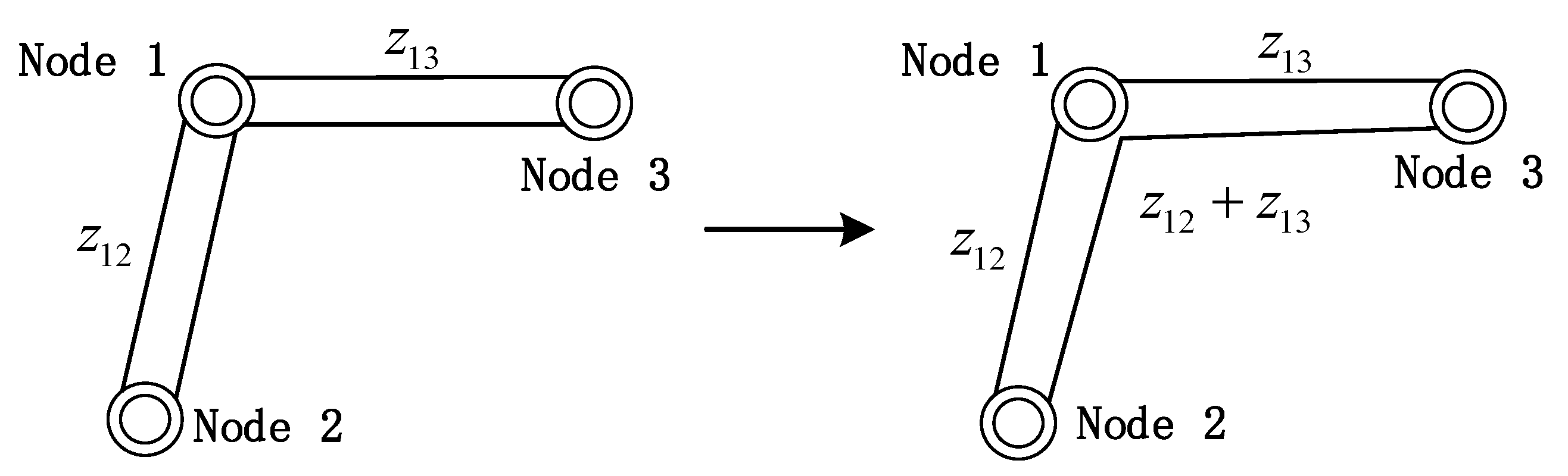
3.3.3. Line Output String

The line output string method involves controlling the opening and closing of circuit breakers within a substation to change the configuration of line connections, thereby reducing the number of outgoing lines from the substation and lowering short-circuit currents. This method is particularly suitable for substations with a 3/2 wiring configuration. In China’s power systems with voltage levels ranging from 330 kV to 500 kV, when a substation has six or more incoming and outgoing lines, the wiring configuration should adopt the 3/2 form. A typical schematic diagram of 3/2 wiring is shown in Figure 10.
In Figure 10, two sets of busbars, W1 and W2, are connected in a series configuration through three circuit breakers. Each incoming line, G1–G4, and outgoing line, WL1–WL4, is connected to the respective busbar via a circuit breaker, with a set of isolating switches located on either side of each circuit breaker. When the complete series is in operation, all busbars are active, and the circuit breakers and isolating switches are closed, forming a highly reliable multi-loop power supply mode. When any circuit breaker in the series goes offline for operation or maintenance, it results in an incomplete series operation mode, but this does not affect the operation of any other components. Therefore, the 3/2 wiring configuration is highly applicable to substations with a large number of outgoing lines.
The 3/2 wiring form not only offers significant advantages for the stable operation of power systems but also facilitates the implementation of line series disconnection to control the short-circuit current of the substation. Ignoring the isolating switches in Figure 10, a simplified diagram of 3/2 wiring is presented in Figure 11 to illustrate the principle of line output string.
In Figure 11, the first series shows a cross connection, while the second series represents a non-cross connection. During complete series operation, all circuit breakers, QF1 to QF6, are in the closed position. To enable the first series of lines, which includes the incoming line G1 and the outgoing line WL1, to operate line output string, circuit breakers QF1 and QF3 need to be opened while keeping QF2 closed. This allows the incoming line G1 and the outgoing line WF1 to form a complete circuit without passing through the substation, thus preventing the substation from supplying short-circuit current during a fault, thereby limiting the short-circuit current.
The operating principle of the second series of lines is the same; circuit breaker QF5 should remain closed while circuit breakers QF4 and QF6 are opened. From a broader perspective, the line output string connects two branches that were originally connected to the same substation, bypassing the substation itself, and connecting the two terminal substations. This method weakens the structure of the intermediate substation to reduce its short-circuit current, which is why it is also referred to as a “jump line.” A schematic diagram of the line output string is shown in Figure 12.
In Figure 12, enabling the line output string at node 1 allows nodes 2 and 3, which were originally unconnected, to be linked through a newly formed branch. The length and impedance of the new line will be equal to the sum of the two original branches, and the load capacity of the line will be determined by the smaller value of the two original branches. To calculate the effect of the line output string in limiting short-circuit current, we can divide the impedance matrix transformation into three steps, as follows:
(1)
Disconnect line 1 between node 2 and node 1.
Introduce a “chain branch” by connecting a new branch with an impedance of z 12 between the two points, and update the admittance matrix elements as follows:
Z 11 = Z 11 Z L 1 2 Z L L = Z 11 Z 11 Z 12 2 Z 22 + Z 11 2 Z 12 z 12 Z 12 = Z 12 Z L 1 Z L 2 Z L L = Z 12 ( Z 11 Z 12 ) ( Z 12 Z 22 ) Z 22 + Z 11 2 Z 12 z 12 Z 13 = Z 13 Z L 1 Z L 3 Z L L = Z 13 ( Z 11 Z 13 ) ( Z 13 Z 33 ) Z 22 + Z 11 2 Z 12 z 12 Z 23 = Z 23 Z L 2 Z L 3 Z L L = Z 23 ( Z 12 Z 22 ) ( Z 13 Z 23 ) Z 22 + Z 11 2 Z 12 z 12 Z 33 = Z 33 Z L 3 2 Z L L = Z 33 Z 13 Z 33 2 Z 22 + Z 11 2 Z 12 z 12
(2)
Disconnect line 1 between node 3 and node 1.
Introduce a “chain branch” by connecting a new branch with an impedance of z 13 between the two points and update the admittance matrix elements for the second time.
Z 11 = Z 11 ( Z L 1 ) 2 Z L L = Z 11 Z 11 Z 13 2 Z 33 + Z 11 2 Z 13 z 13 Z 12 = Z 12 Z L 1 Z L 2 Z L L = Z 12 ( Z 11 Z 13 ) ( Z 21 Z 23 ) Z 33 + Z 11 2 Z 13 z 13 Z 13 = Z 13 Z L 1 Z L 3 Z L L = Z 13 ( Z 11 Z 13 ) ( Z 31 Z 33 ) Z 33 + Z 11 2 Z 13 z 13 Z 22 = Z 22 ( Z L 2 ) 2 Z L L = Z 22 Z 12 Z 23 2 Z 33 + Z 11 2 Z 13 z 13 Z 23 = Z 23 Z L 2 Z L 3 Z L L = Z 23 ( Z 12 Z 23 ) ( Z 13 Z 33 ) Z 33 + Z 11 2 Z 13 z 13 Z 33 = Z 33 ( Z L 3 ) 2 Z L L = Z 33 Z 13 Z 33 2 Z 33 + Z 11 2 Z 13 z 13
(3)
Add a new line between node 2 and node 3.
Introduce a “chain branch” by connecting a new branch with an impedance of z 12 + z 13 between the two points and update the admittance matrix elements for the third time to obtain the admittance matrix element Z 11 for calculating the short-circuit current at node 1.
Z 11 = Z 11 ( Z L 1 ) 2 Z L L = Z 11 Z 12 Z 13 2 Z 33 + Z 22 2 Z 23 + z 12 + z 13
The change in short-circuit current at node 1 is
Δ I = 1 Z 11 1 Z 11
The line output string not only limits the short-circuit current at the substation but also somewhat weakens the network structure of the substation, which visually translates to a reduction of 2 in the number of connected branches at the substation. Therefore, to satisfy the “N − 1” principle, the minimum number of branches at the substation implementing line disconnection should be 4, ensuring that after a “line trip”, the substation still retains two branches. This prevents a situation where a fault in one line could cause a loss of power at the substation. Even if the above conditions are met, a stability assessment of the system after implementing the disconnection measures should be conducted to ensure the safe and reliable power supply of the grid.
In summary, the applicable conditions for all current-limiting measures discussed in this paper are consolidated in Table 2.

4. Simulation Analysis of Current-Limiting Cases

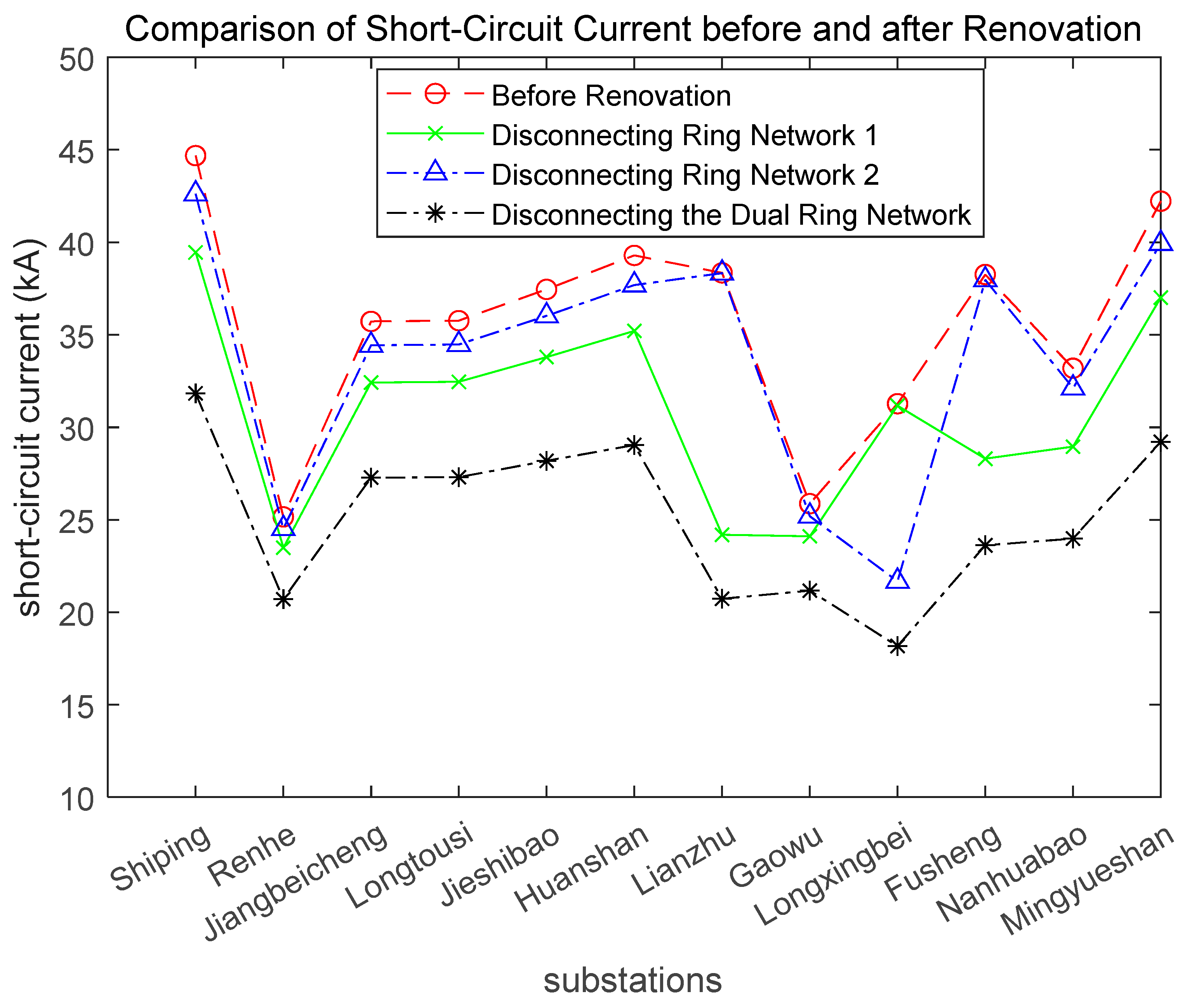
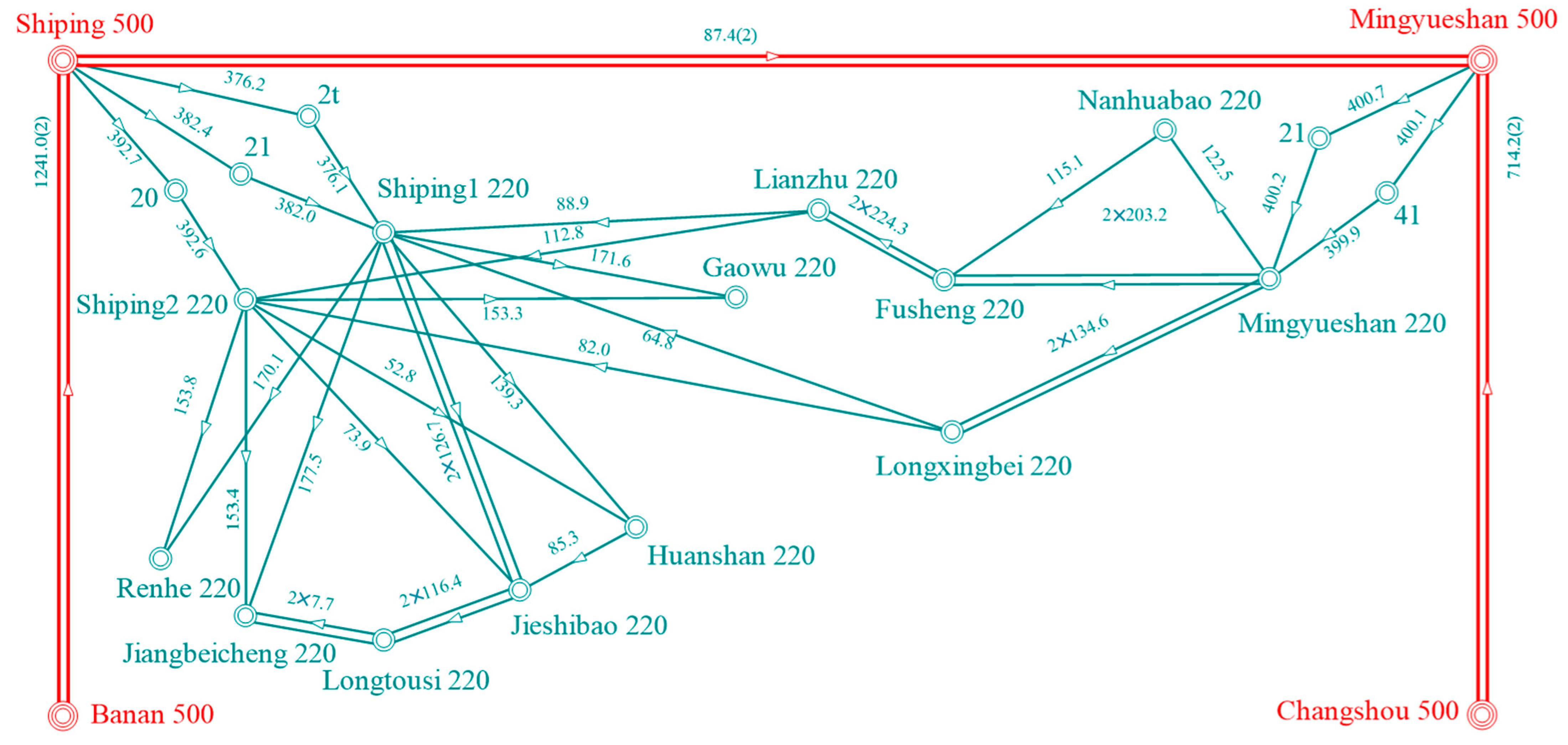
4.1. Simulation and Calculation of Measures for Significant Changes in Power Grid Structure

The power grid in a certain area is shown in Figure 13. This region has a high level of power grid development and has formed a dual electromagnetic ring network structure with high and low voltage levels of 500–220 kV.
Ring Network 1: Shiping 500 kV–Shiping 220 kV–Lianzhu 220 kV–Fusheng 220 kV–Mingyueshan 220 kV–Mingyueshan 500 kV–Shiping 500 kV.
Ring Network 2: Shiping 500 kV–Shiping 220 kV–Longxingbei 220 kV–Mingyueshan 220 kV–Mingyueshan 500 kV–Shiping 500 kV.
When no measures are taken, the short-circuit current level of the 220 kV station in the area is shown in Table 3.
Disconnecting the electromagnetic ring network can effectively reduce the short-circuit current levels in the 220 kV power grid. The existing methods for disconnecting the ring network are as follows:
(1)
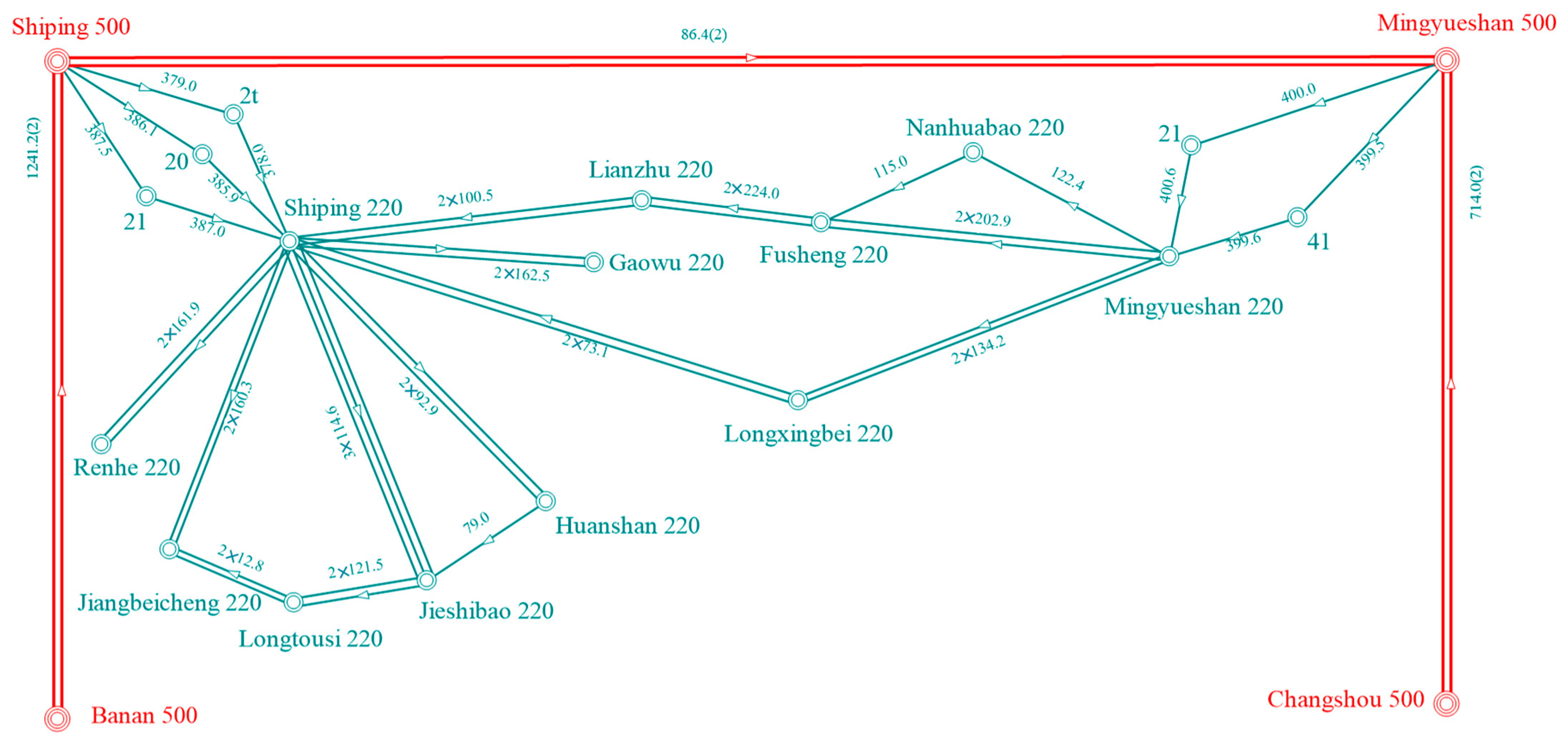
Disconnecting Ring Network 1: Break the dual circuit of Shiping 220 kV–Lianzhu 220 kV.
(2)
Disconnecting Ring Network 2: Break the dual circuit of Shiping 220 kV–Longxingbei 220 kV.
(3)
Disconnecting the Dual Ring Network: Break the dual circuit of Shiping 220 kV–Lianzhu 220 kV and break the dual circuit of Shiping 220 kV–Longxingbei 220 kV.
A comparison of short-circuit current levels before and after disconnection is shown in Figure 14.
It can be seen that disconnecting the electromagnetic ring network can reduce the short-circuit current levels in substations within a large area near the disconnection point. The more thoroughly the network is disconnected, the more significant the reduction in short-circuit current, particularly in weaker network structures.
The concept of power grid layering and zoning is large-scale and involves the detailed long-term planning of the entire power grid, including the construction of higher voltage levels and the reasonable planning of zoning structures. This process is accompanied by significant changes in the structure and parameters of the large power grid, making results obtained from small simulation cases quite inaccurate. Here, some examples from domestic and international power grids are presented to illustrate the current-limiting effects of power grid layering and zoning: In the 1970s, the short-circuit current level of Japan’s 275 kV power grid nearly reached 50 kA. After constructing a 500 kV power grid, the 275 kV network was operated in sub-zones, leading to a gradual decrease in the short-circuit current level of the 275 kV grid. By the end of the “Twelfth Five-Year Plan” in China, the short-circuit current at the 330 kV bus of the Ningxia power grid is expected to exceed 60 kA. However, after constructing a 750 kV power grid and partially disconnecting the 330 kV grid, the short-circuit current in all 330 kV substations can be limited to below 50 kA.
Overall, such measures are often accompanied by significant changes in the structure of the power network, resulting in a noticeable reduction in short-circuit currents at substations in areas near the changes. These measures are among the most effective and impactful for limiting short-circuit currents. However, the investment in such measures often leads to a substantial weakening of the grid’s structural integrity. Therefore, to ensure the safe and reliable operation of the power grid, these measures have high requirements for the grid structure. They are particularly suitable for power grids that are highly developed and structurally robust.

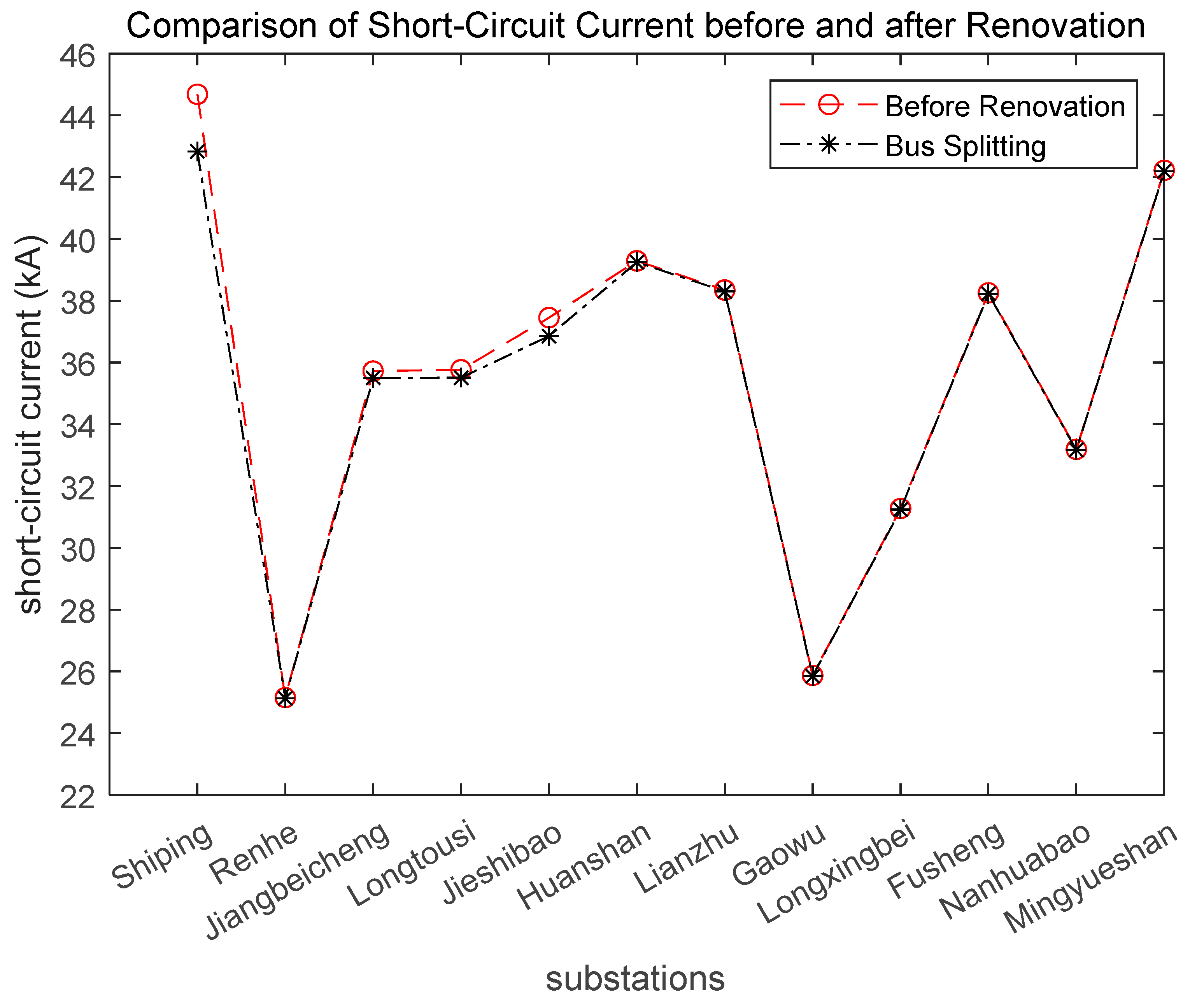
4.2. Simulation and Calculation of Measures for Partial Changes in Power Grid Structure

Still taking the power grid shown in Figure 13 as an example, we will implement bus splitting at the Shiping 220 kV substation in that grid: a new 220 kV node, Shiping 2, will be established. One of the dual circuit branches connecting to the original Shiping 220 kV substation will be redirected to Shiping 2. The branch of the original Shiping to Jieshibao three-circuit line will be split in a ratio of 1:2, with one of the lines redirected to Shiping 2. Additionally, one of the three 500/220 kV transformers between the original Shiping substation and the higher-level Shiping 500 kV substation will also be split in a ratio of 1:2, with one unit connected to Shiping 2. The structure of the grid after bus splitting is shown in Figure 15, and the short-circuit current conditions at substations within this area are presented in Table 4.
The comparison between the short-circuit current data after bus splitting and the original data in Table 3 is shown in Figure 16.
From Figure 16, it can be observed that bus splitting has a significant effect in reducing the short-circuit current levels of the modified bus. In this case, the short-circuit current decreased by approximately 1.8 kA. Additionally, the substations directly connected to the modified bus (such as Jiangbeicheng and Longtousi substations) experienced a certain degree of weakening in their wiring structures due to the bus splitting, resulting in a slight reduction in their short-circuit current levels, as well. However, the substations that are relatively far from the modified bus (such as those on the Mingyueshan side) did not exhibit a significant decrease in short-circuit current levels.
Dynamic opening and closing circuit breakers can achieve the effect of bus splitting only during grid faults, using a complete system that allows the grid to return to its original topology after the fault is cleared. This approach meets the requirements for short-circuit current during grid faults while ensuring a strong and stable power supply during normal operation. However, due to the high cost of the entire system and equipment, as well as certain technical issues, this technology has not yet been widely applied. The fault data from dynamic opening and closing circuit breakers are consistent with the bus splitting data, while the non-fault data remain consistent with the original grid, so no additional simulations are necessary.
Overall, such measures have certain requirements for the strength of the power grid. The range of structural weakening in the grid is somewhat smaller compared to the first type of measure, which results in a correspondingly smaller scope of substations with limited short-circuit currents. Nevertheless, the current-limiting effect for the modified bus is significant.

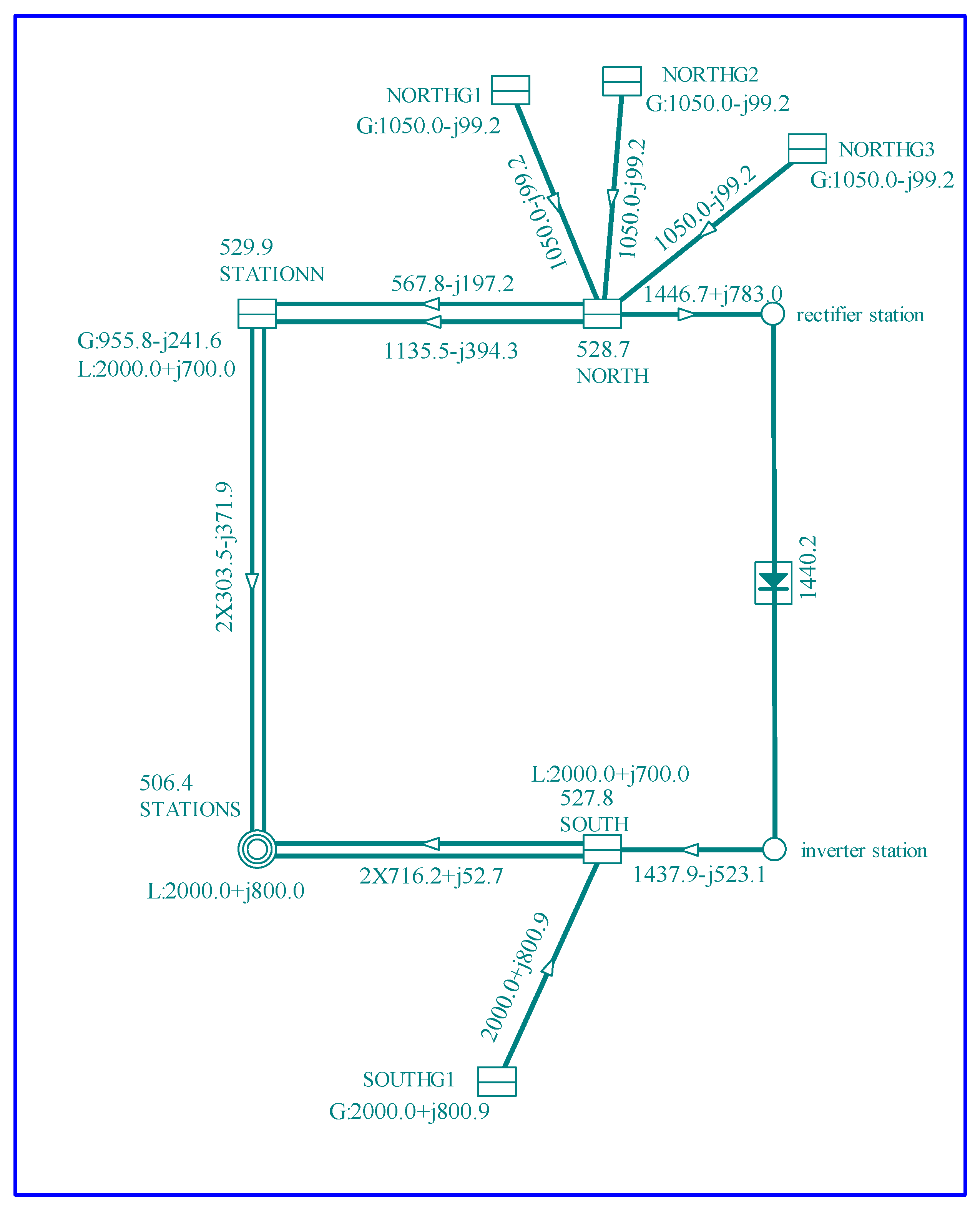
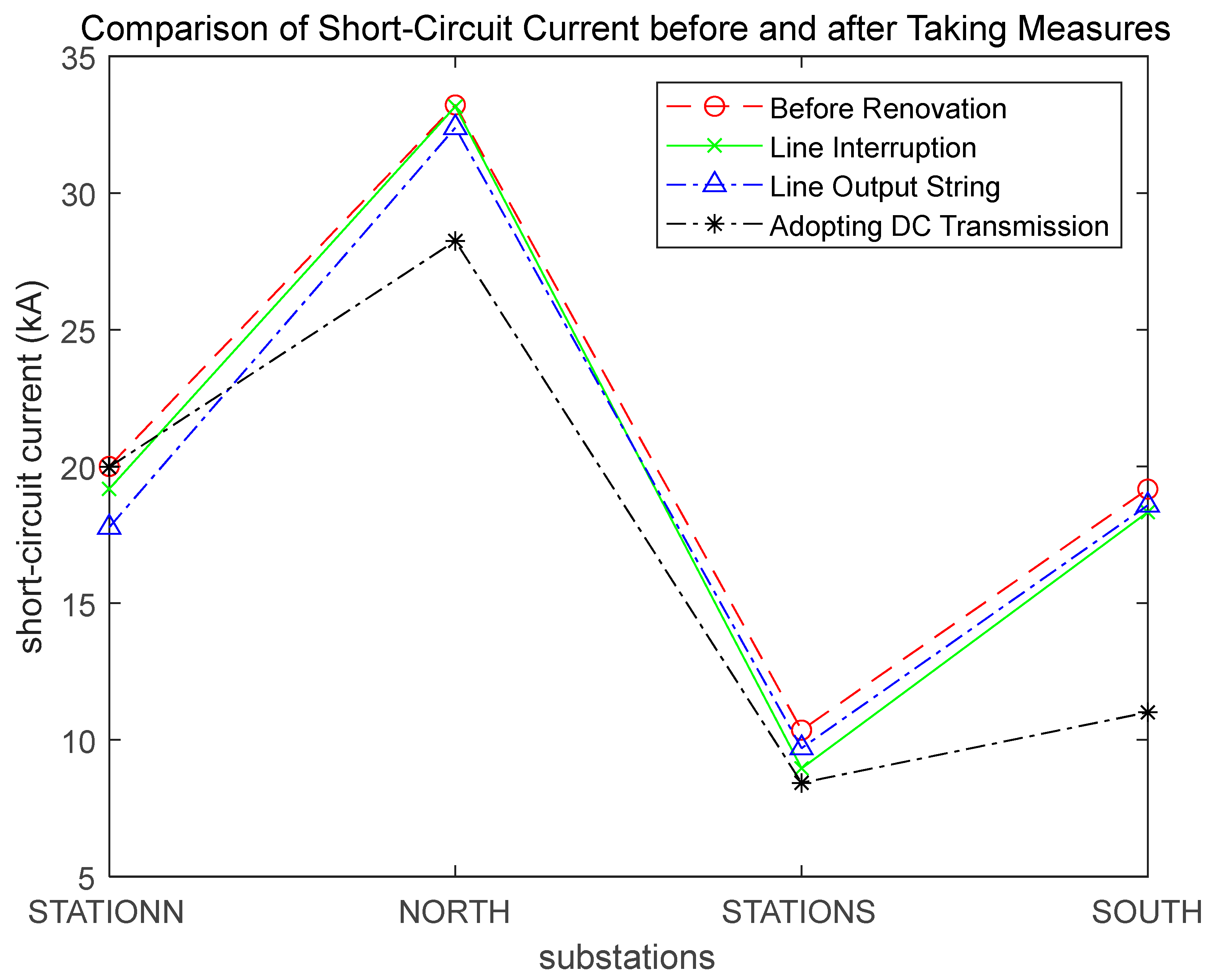
4.3. Simulation and Calculation of Measures for Switching Power Grid Lines

Taking the system shown in Figure 17 as an example, we will illustrate the current-limiting effect of these measures. This system consists of four 500 kV substations: STATIONN, STATIONS, NORTH, and SOUTH, which are interconnected to form a ring structure. The NORTH substation is connected to three sets of 20 kV power supplies, while the SOUTH substation is connected to one set of power supplies. The substations and power supplies are interconnected via four 500/20 kV transformers. Under conditions without any modification measures, the short-circuit current levels of the four substations are shown in Table 5.
The current-limiting measures are as follows:
(1)
Line interruption: Disconnect branch 1 between STATIONN and STATIONS, and retain the single return line.
(2)
Line output string: At the STATIONN station, “jump line” is used to complete the line output stringing of STATIONS-STATIONN-North.
(3)
Adopting direct current transmission: Transform the North and South AC double circuit branches into DC lines. After introducing the DC system, the power grid is shown in Figure 18.
After taking measures, the short-circuit current level of the system is shown in Table 6.
Plot four sets of data to compare the current-limiting effects of each measure, as shown in Figure 19.
As seen in Figure 19, line interruption has a significant current-limiting effect on the substations at both ends of the broken line (STATIONN and STATIONS), and the current-limiting effect on other substations is general. The line output string of the line shows the most pronounced current-limiting effect on the substation that is “jumped” (STATIONN), and the current-limiting effect on other substations is weak. The DC system has a strong regulating function on the current of the power grid due to the highly controllable nature of the equipment and has certain current-limiting effect on the neighboring substations, especially on the ends of the modified line (NORTH and SOUTH).
Since this type of measure is based on a certain line, the parts with an obvious current-limiting effect are mainly distributed in the vicinity of the line to be rebuilt. For urban power grids with high loads and limited space, line cutting and the ‘’Jump Line’’ may cause line overloading and other problems due to the reduction in lines; therefore, under these conditions, if economic conditions allow, it is preferable to use DC lines for power grid reconstruction.
Regardless of which of the above measures is taken, the average short-circuit current across the entire network is reduced to varying degrees. These measures are aimed at specific lines, effectively increasing the electrical distance and serving to isolate certain areas. After the conversion, the substations at both ends of the line no longer supply short-circuit currents to each other, resulting in a good current-limiting effect for regions where local short-circuit currents exceed standards.

5. Conclusions

This paper addresses the increasingly severe issue of excessive short-circuit currents arising from the rapid development of large-scale power grids. We studied the operational principles, applicable conditions, and current-limiting effects of measures that change the grid structure to limit short-circuit currents and conducted simulation analysis through specific grid case studies. The following conclusions were drawn:
(1)
There are generally two factors that cause changes in the grid impedance matrix: one is the change in the topology of the power system; the other is the change in the parameters of the power system. Short-circuit-current-limiting measures can be categorized based on their operational forms into two types: changing the structure of the power system and modifying the equipment of the power system. Changing the structure corresponds to the first factor, while modifying the equipment corresponds to the second factor, which causes changes in the impedance matrix.
(2)
The layered and zoned management of the power grid is a fundamental measure in solving the problem of excessive short-circuit currents and is an inevitable trend in the long-term development of the grid. However, the implementation process is relatively long-term and requires a high level of grid development. Electromagnetic loop network disconnection can effectively reduce the short-circuit current levels in lower-level grids, but it may result in a loss of partial supply reliability for those grids.
(3)
Bus-splitting operation has low costs and simple operation, effectively targeting and limiting the short-circuit currents of specific “split-bus” substations. However, it lacks the flexibility and reliability in power supply that comes with double-bus connections and may also lead to uneven load distribution. Dynamic circuit breaker operation can compensate for the shortcomings of traditional bus-splitting operations, but the entire system is expensive and has technological issues that prevent large-scale use.
(4)
Line interruption has a good current-limiting effect, is easy to operate, and does not incur cost issues, but it may lead to overloads in other lines and also waste grid resources. DC transmission offers a high level of controllability over short-circuit currents, but it has high requirements for power mutual assistance and supply reliability. A line output string is simple and effective for current limiting, but there should be certain limitations on the number of branches connected to the substations implementing this measure.
(5)
While each current-limiting measure effectively limits short-circuit currents, it also brings about corresponding issues for grid operation. Therefore, in addition to short-circuit calculations, comprehensive consideration should be given to stability calculations, power flow calculations, and economic costs. After comprehensive evaluation, the optimal solution to address the problem of excessive short-circuit currents should be obtained.

Author Contributions

Conceptualization, S.S. and G.Z.; methodology, G.Z.; software, Y.S.; validation, G.Z. and Y.Z.; formal analysis, Z.Y.; investigation, Y.Z.; resources, Y.Z. and Y.S.; data curation, G.Z. and Y.S.; writing—original draft preparation, G.Z., S.S. and Y.S.; writing—review and editing, G.Z., S.S. and X.T.; visualization, X.T. and S.S.; supervision Y.S. and Y.Z.; project administration, S.S.; funding acquisition S.S. All authors have read and agreed to the published version of the manuscript.

Funding

This research was funded by Chinese Academy of Engineering Strategic Research and Advisory Project (JL2024-13) and Jilin University Teaching Research Project (2023CGP009).

Data Availability Statement

Data are contained within the article.

Conflicts of Interest

Author Yuguang Zhou was employed by the company Dandong Jinshan Thermal Power Co., Ltd. The remaining authors declare that the research was conducted in the absence of any commercial or financial relationships that could be construed as a potential conflict of interest.

References

  1. Eroshenko, S.; Egorov, A.; Senyuk, M.; Khalyasmaa, A. Practical experience in short-circuit current limiting measures implementation. In Proceedings of the 2017 IEEE Conference of Russian Young Researchers in Electrical and Electronic Engineering (EIConRus), St. Petersburg and Moscow, Russia, 1–3 February 2017; pp. 1326–1331. [Google Scholar]
  2. Jin, X.; Duan, K.Y.; Zhuang, W.Q. Short-circuit current limiting methods for power networks. J. Electr. Power Sci. Technol. 2008, 23, 78–82. [Google Scholar]
  3. Schlabbach, J. Limitation of Short-Circuit Currents. In Short Circuit Currents; The Institution of Engineering and Technology: Stevenage, UK, 2005; pp. 225–244. [Google Scholar] [CrossRef]
  4. Vorkunov, O.; Glotkina, L.; Sinicin, A. Short-Circuit Current Limitation. In Proceedings of the 2024 International Conference on Industrial Engineering, Applications and Manufacturing (ICIEAM), Sochi, Russia, 20–24 May 2024; pp. 315–320. [Google Scholar]
  5. Liu, B.; Li, Y.; Xi, J.; Xu, Y. Analysis of Pulling Switch to Limit Short-circuit Current in 3/2 Wiring Substation. Autom. Electr. Power Syst. 2014, 38, 131–135. [Google Scholar]
  6. Han, G.; Han, L.; Wu, L. Application and development of methods on limiting power grid’s short-circuit current. Power Syst. Prot. Control 2010, 38, 141–144. [Google Scholar]
  7. Yuan, J.; Liu, W.; Dong, M.; Shi, K.; Fan, Y. Application of Measures Limiting Short Circuit Currents in Northwest China Power Grid. Power Syst. Technol. 2007, 31, 42–45. [Google Scholar]
  8. Xiong, W.; Lu, H. Analysis of short circuit current level of Guangdong Province power system and limiting measures. J. Guizhou Univ. Technol. 2002, 31, 32–35. [Google Scholar]
  9. Lu, B.; Huang, M.; Huang, Y.; Tian, B. Application of short-circuit current limitation technology to Ningxia Power Grid. East China Electr. Power 2008, 36, 40–42. [Google Scholar]
  10. Pan, X.; Wang, H.; Liu, F.; Gao, Z.; Tian, C.; Zhang, H. A New Method of Short-circuit Current Limitation for Henan 500 kV Power Grid. In Proceedings of the 2022 7th Asia Conference on Power and Electrical Engineering (ACPEE), Hangzhou, China, 15–17 April 2022; pp. 45–49. [Google Scholar]
  11. Qi, S.; Pi, J.; Wu, H.; Ma, X. Grid Optimization Based on Sensitivity Analysis for Limiting Short-circuit Current of Power System. In Proceedings of the 2022 IEEE 6th Conference on Energy Internet and Energy System Integration (EI2), Chengdu, China, 11–13 November 2022; pp. 1096–1101. [Google Scholar]
  12. Zhang, K.; Hu, J.; Lu, X.; Peng, Z.; Ma, P.; Gao, F. Influence of fast switching fault current limiter on electromagnetic transient of extra-high voltage transmission line. J. Phys. Conf. Ser. 2024, 2903, 012007. [Google Scholar] [CrossRef]
  13. Ren, H.; Zhang, Y. Analysis of Transient Recovery Voltage of 500 kV Line Considering Current Limiting Reactor. J. Phys. Conf. Ser. 2023, 2488, 012036. [Google Scholar] [CrossRef]
  14. Zhang, L.; Yu, Y.; Liu, S.; Guo, J. Research on Short-Circuit Current Suppression Based on Equivalent Sensitivity. In Proceedings of the 2020 International Conference on Urban Engineering and Management Science (ICUEMS), Zhuhai, China, 24–26 April 2020; pp. 251–255. [Google Scholar]
  15. Yang, Z.; Li, L.; Li, Y.; Wang, K. The Issue of Short-circuit Current Being out of Limitation in Guangdong Power Grid and Related Countermeasures. South. Power Syst. Technol. 2011, 5, 90–93. [Google Scholar]
  16. Viktorovich, K.A.; Petrovich, Y.Y.; Aleksandrovich, M.A. The Problem of Short-circuit Current Limitation in Energy–saving Systems of Transportation and Electricity Distribution. In Proceedings of the 2021 12th International Symposium on Advanced Topics in Electrical Engineering (ATEE), Bucharest, Romania, 25–27 March 2021; pp. 1–5. [Google Scholar]
  17. Safonov, E.; Frolov, V.; Zhiligotov, R.; Petrenya, Y. On the Problems of Current Limitations in Networks Based on Power Semiconductor Devices. Energies 2023, 16, 5905. [Google Scholar] [CrossRef]
  18. Luo, F.; Zhang, C.; Liu, F.; Bai, S.; Xiang, L.; Zhong, H. Research on Limiting Measures for DC Component of Short Circuit Current Based on Fault Current Limiter and Selection of Installation Site. In Proceedings of the 2019 IEEE Asia Power and Energy Engineering Conference (APEEC), Chengdu, China, 29–31 March 2019; pp. 89–93. [Google Scholar]
  19. Ma, K. Research and Application of 220kV Short-Circuit Current Limiting Measures Based on Fast Switch. In Proceedings of the 2022 IEEE Asia-Pacific Conference on Image Processing, Electronics and Computers (IPEC), Dalian, China, 14–16 April 2022; pp. 948–951. [Google Scholar]
  20. Castro, L.; Guillen, D.; Trillaud, F. On Short-Circuit Current Calculations Including Superconducting Fault Current Limiters (ScFCLs). IEEE Trans. Power Deliv. 2018, 33, 2513–2523. [Google Scholar] [CrossRef]
  21. Yu, Y.; Pan, T.; Rui, J.; Chen, S.; Fan, Y. Design and analysis of a peak current-limiting device using an oscillating zero-crossing circuit. Electr. Power Syst. Res. 2025, 242, 111465. [Google Scholar] [CrossRef]
  22. Han, L.; Qiu, W.; Xiao, Z. Overview on Measures of Short-Circuit Current Limitation on Power System. Electr. Power Technol. Econ. 2009, 21, 33–37. [Google Scholar]
  23. Sun, S.; Zhou, G.; Song, Y.; Tang, X.; Yuan, Z.; Qi, X. Research on Optimization Method of Short-Circuit Current-Limiting Measures Based on Combination Assignment. Energies 2024, 17, 5724. [Google Scholar] [CrossRef]
Figure 1. Schematic diagram of 220 kV power grid.
Energies 18 02098 g001
Figure 2. Schematic diagram of power grid layering and zoning.
Energies 18 02098 g002
Figure 3. Schematic diagram of the 500–220 kV electromagnetic ring network.
Energies 18 02098 g003
Figure 4. Simplified model of 500–220 kV electromagnetic loop network.
Energies 18 02098 g004
Figure 5. The 220 kV double-busbar wiring structure.
Energies 18 02098 g005
Figure 6. Wiring structure after bus-splitting operation.
Energies 18 02098 g006
Figure 7. Timing diagram of dynamic opening and closing circuit breaker device operation.
Energies 18 02098 g007
Figure 8. Equivalent circuit of line interruption.
Energies 18 02098 g008
Figure 9. Flexible closed-loop wiring form for 500 kV dual-ring power supply and 220 kV partitioned mutual supply.
Energies 18 02098 g009
Figure 10. Schematic diagram of 3/2 connection in substation.
Energies 18 02098 g010
Figure 11. Simplified schematic diagram of 3/2 wiring.
Energies 18 02098 g011
Figure 12. Schematic diagram of line output string.
Energies 18 02098 g012
Figure 13. The 500–220 kV high- and low-voltage electromagnetic ring network structure in a certain region.
Energies 18 02098 g013
Figure 14. Comparison of short-circuit current in the area before and after electromagnetic ring network disconnection.
Energies 18 02098 g014
Figure 15. Structural diagram of a power grid in a certain area after bus splitting.
Energies 18 02098 g015
Figure 16. Comparison of short-circuit current before and after bus splitting.
Energies 18 02098 g016
Figure 17. Diagram of 8-node system.
Energies 18 02098 g017
Figure 18. System diagram after introducing DC lines.
Energies 18 02098 g018
Figure 19. Comparison of short-circuit current before and after adopting current-limiting measures.
Energies 18 02098 g019
Table 1. The upper limit of short-circuit current for each voltage level.
Voltage Level (kV)Short-Circuit Current Control Value (kA)Voltage Level (kV)Short-Circuit Current Control Value (kA)
10005011040
750636631.5
500633525
330632020
220501020
Table 2. Brief description of selection criteria for short-circuit-current-limiting measures.
Current-Limiting MeasuresSelected Condition
Power grid layering and zoningThe structure of the upper and lower power grids is strong, especially in limiting the short-circuit current of the lower power grids, which has a significant effect
Electromagnetic ring network breakingHaving the conditions for developing a higher voltage level power grid and ensuring that the reliability of power supply is not affected after partitioning the lower-level power grid
Bus splittingWhen there are multiple branches connected to the busbar, it is advisable to have at least four connecting transformers connected to the busbar
Dynamic opening and closing of circuit breakerThere are locations within the station where monitoring and control systems are installed, and changing the structure of the power grid has a significant impact on its characteristics
Line interruptionThe power flow of the line is small
Adopting direct current transmissionIt has high requirements for power mutual benefit and power supply reliability, especially suitable for the transformation of inter-zone interconnection lines in the power grid
Line output stringThe substation has four or more lines
Table 3. The original short-circuit current level of the 220 kV grid in the region.
SubstationShort-Circuit Current (kA)SubstationShort-Circuit Current (kA)
Shiping44.688Lianzhu38.348
Renhe25.153Gaowu25.872
Jiangbeicheng35.723Longxingbei31.274
Longtousi35.767Fusheng38.259
Jieshibao37.455Nanhuabao33.191
Huanshan39.292Mingyueshan42.226
Table 4. Short-circuit current level of substations in the area after bus splitting.
SubstationShort-Circuit Current (kA)SubstationShort-Circuit Current (kA)
Shiping 1/Shiping 242.838/41.157Lianzhu38.306
Renhe25.127Gaowu25.845
Jiangbeicheng35.505Longxingbei31.240
Longtousi35.509Fusheng38.225
Jieshibao36.857Nanhuabao33.170
Huanshan39.249Mingyueshan42.195
Table 5. Short-circuit current level before taking measures.
SubstationShort-Circuit Current (kA)
STATIONN20.00
NORTH33.22
STATIONS10.36
SOUTH19.17
Table 6. Short-circuit current level after taking measures.
Current-Limiting MeasuresSubstationShort-Circuit Current (kA)
Line interruptionSTATIONN19.18
NORTH33.16
STATIONS8.96
SOUTH18.33
Line output stringSTATIONN17.77
NORTH32.39
STATIONS9.70
SOUTH18.58
Direct current transmissionSTATIONN19.98
NORTH28.25
STATIONS8.43
SOUTH11.01
Disclaimer/Publisher’s Note: The statements, opinions and data contained in all publications are solely those of the individual author(s) and contributor(s) and not of MDPI and/or the editor(s). MDPI and/or the editor(s) disclaim responsibility for any injury to people or property resulting from any ideas, methods, instructions or products referred to in the content.

