Abstract
Nowadays, the development of innovative and feasible sustainable solutions able to reduce lighting costs and enhance the building’s energy efficiency is a hot topic and one of the most challenging research avenues. In this context, fiber optic daylight (FOD) systems are a growing technology, where fiber optics can be used as a waveguide to transmit sunlight into the interior of windowless spaces. This review aims to track, analyze, and discuss the application of integrated FOD systems with concentrating solar collectors and provide a clear understanding of FOD system requirements and overall performance. In view of this, a comprehensive analysis of the most recent FOD systems, along with their different applications, has been provided to ensure a complete overview of the current state of FOD systems in terms of actual technological strengths, limitations, cost-effectiveness, and future application performance. Therefore, this paper comprehensively analyzes the structure and performance of FOD systems. It highlights the recent development and nanotechnology applications of FOD systems. Additionally, this article discusses the challenges of building-integrated FOD systems and the benefits of using FOD instead of conventional grid-integrated lighting devices and systems.
1. Introduction
Solar energy offers a tremendous resource for the world, and its usage should be improved. This energy might be particularly beneficial in countries with high insolation as it decreases reliance on fossil fuels. Unfortunately, conventional technologies for electric power production cannot efficiently rely on solar energy because it is normally diffuse. Therefore, systems with concentrating optics are required to transform diffuse solar energy into concentrated energy, which can then be converted into other types of energy through heat engines. Solar-concentrating systems typically track the sun with mechanical structures but can also be classified as non-tracking (passive) or tracking (active) systems. Non-tracking systems are designed to collect sun radiation at a wider range of acceptance angles, requiring a full understanding of the spatial and temporal fluctuation of direct solar radiation. The concentration ratios reached by both technologies are different due to engineering and technological restrictions. Solar optics provide maximum optical concentration ratios equivalent to 1000 suns (for this value, the theoretical energy conversion effectiveness reaches 40%) [1,2]. Enhancing the solar energy conversion efficiency would also be beneficial for PVs, as they could work at lower temperatures and heat and be used in domestic or industrial applications [3]. Today, solar energy technology is one of the primary interests of energy researchers in the 21st century. The sun’s vast energy potential (170,000 terawatts per hour) remains underexploited. Research has shown great promise in utilizing solar energy in photovoltaic cells and thermal heat for power plants, but the intensity of sunlight on the earth will eventually decrease, exposing only some areas to inefficient, low-intensity sunlight. Concentrating the wide expanse of sunlight on the earth’s surface is one solution. The small size of existing designs is an important barrier to their wider use on rooftops and foliage, thus hindering future adoption. Currently, the sun is captured from a large aperture lens and conveyed to the small-diameter fiber, which is then fed onto a photovoltaic device or, most frequently, to the light diffusers. Furthermore, this image of the sun can be obliterated, and more importantly, the optical efficiency of such a design drops drastically for angles of incidence greater than 5°. All previous designs have had very careful restrictions on feed angles or used fibers that work with only a narrow band of wavelengths. The currently developed designs and the ongoing projects attempt to address these problems and design low-cost, high-efficiency daylight systems combined with concentrating solar collectors [4]. Fiber optics, or optical fibers, are known as “optical pipes” that route sunlight by guiding it using total internal reflection. Fiber optics are a cutting-edge technology that holds great potential for transferring daylight in various applications. Several different varieties of optical fibers exist, with some being very small for endoscopes or image conduits and others being large for telecommunication, illumination, imaging, photometry, and sensing. Despite being useful in many applications, very little work has been done on fiber optics coupled with solar energy collectors for daylight applications. This is due, in part, to the difficulty of capturing and routing sunlight efficiently using small-diameter fiber optical pipes. Fiber optic solar concentrators are necessary for rooftop applications and systems that are built into buildings. All these applications would benefit from the existence of efficient small optical fiber sunlight systems capable of harvesting concentrated solar energy. All existing optical fiber concentrators are discussed in detail in Section 5.
Fiber optics can transfer light into indoor environments using the principle of total internal reflection (TIR), where light is transmitted through the core of the fiber by bouncing off the walls due to the difference in the refractive indices of the core and the cladding [5,6,7,8]. This innovative use of fiber optics allows the collection and transmission of natural light to buildings without the need for traditional artificial lighting sources. Many approaches have been explored to improve the efficiency and effectiveness of fiber optic daylighting systems. One approach was to utilize a parabolic concentrator to collect and focus sunlight into a collimating lens, which then distributes the light evenly over each optical fiber in the bundle [9]. Another approach was to use a Fresnel lens with a diameter of 1 m, which collects an enormous amount of sunlight flux. In this approach, to prevent the optic fiber bundle from being burnt at high temperatures, a hot mirror and homogenizer were used. According to the results, the efficiency of daylighting is approximately 13% [10]. Furthermore, a linear Fresnel lens approach has been developed and has achieved an optical efficiency of 16.834%. However, it is important to note that the overall efficiency of this system is low due to the natural characteristics of daylight systems. However, it is still capable of providing sufficient illumination for a room of 2 × 2 m at a rate of 83.33%. If the aim is to achieve an average illumination level of 500 lux, it is important to consider the size of the office area. With an output of 1666.61 Im, this system can provide an average of 416.653 lux within the interior of a four-square-meter room. This accounts for 83.33% of the required illuminance [11]. Daylight systems can be further optimized by hybridization with traditional artificial lighting sources. Such an approach was implemented, and fiber optics combined with an LED lighting system achieved an optical efficiency of 63.8% [12]. Daylight systems have many benefits, such as reducing energy consumption, improving health and well-being, and reducing greenhouse gas emissions [13,14,15]. Figure 1 demonstrates the basic concept of fiber optic daylighting systems.
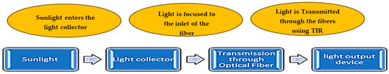
Figure 1.
A schematic diagram illustrating the basic concept of fiber optic daylighting systems.
In light of the above, this review paper aims to provide a comprehensive and detailed examination of several optical fiber concentrating configurations for daylighting systems. The novelty of this review lies in its comprehensive analysis of the structure, fundamentals, potential, and future applications of FOD. This review focuses on the recent developments in material properties and nanotechnology applications for FOD systems. This article highlights the key advantages and benefits of building-integrated fiber optic systems, explores the best practices to overcome the challenges facing fiber optics technology in daylight systems, and paves the way for practical applications. A systematic literature analysis will also be employed to categorize the existing research, focusing on performance metrics such as optical efficiency and cost-effectiveness. This thematic synthesis aims to provide valuable insights into the current state of FOD systems and inform future research directions.
2. Sunlight Variation and Luminous Efficacy
2.1. Sunlight Variation
The performance of daylight systems depends on the local insulation conditions and levels [16]. Sunlight availability is critical for daylight systems because it is influenced by both geographical and seasonal factors. In effect, sites that are close to the equator, such as those within the sunbelt, receive higher average daily solar insolation over the year. Locations at mountain sites or with high urban designs and architectures can also affect sunlight availability by blocking or reflecting sunlight. Seasonal changes in some regions also have an impact on FOD. Bellia et al. found that daylight fluctuations can significantly impact the performance of daylight-linked control systems [17]. Lam and Li recommended the need for accurate solar radiation and outdoor illuminance data to come up with an effective design for daylighting, particularly in hot climates where unwanted solar heat gain can occur [18].
2.2. Luminous Efficacy and Luminous Efficiency
The amount and the fraction of the visible light wavelengths in the sun spectrum are very important in the performance of daylight systems [19]. The relationship between the visible part and the total energy content associated with electromagnetic radiation is the luminous efficacy. It is the ratio of luminous flux (in lumens) to power (usually measured in watts) and, therefore, has units of lumens per watt. Depending on the light source of the daylight system, the power can be either the radiant flux of the light source’s output or the total electric power consumed by the source. The luminous efficacy is expressed as follows [20,21,22,23]:
where (in ) is the spectral radiant flux emitted by the light source, and is the spectral luminosity efficacy. is the luminosity function, which is dimensionless, and an empirically derived composite based on visual response studies of numerous humans. The luminosity function values, which also refer to the relative ability of radiant energy to evoke differing sensations of brightness in humans, are provided by the standard CIE tables. Figure 2 [24] shows the 1931 CIE photopic luminosity function.
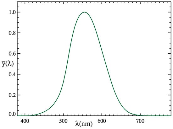
Figure 2.
The 1931 CIE photopic luminosity function.
The total luminous flux in a source of light is the integral of the product of the luminosity function with the spectral power distribution, as follows:
The value of the constant in front of the integral is usually rounded off to 683 lm/W. The small excess fractional value comes from the slight mismatch between the definition of the lumen and the peak of the luminosity function. Therefore, for an ideal monochromatic 555 nm source in air (where ), the luminous efficacy will be approximately 680.002 lm/W, which is the theoretical maximum value. For a light source that generates light centered on 450 and 650 nm, the luminous efficacy will be 26 and 73 lm/W, respectively. Whilst luminous efficacy is a measure of how well a light source produces visible light, luminous efficiency goes beyond the relationship between the luminous flux and power consumption of a light source. It is defined as the luminous efficacy divided by the maximum possible value of the efficacy. It is expressed as a value between 0 and 1, with 1 corresponding to an efficacy of 683.002 lm/W. In some systems of units, luminous flux has the same units as radiant flux. The luminous efficacy of radiation is then dimensionless. In this case, it is often called luminous efficiency instead and may be expressed as a percentage. A common choice is to choose units such that the maximum possible efficacy, 683.002 lm/W, corresponds to an efficiency of 100%. Moreover, the luminous efficacy of sunlight varies with altitude; it is almost constant at 117 for solar altitudes above 25 degrees [25]. With reference to the conventional heat-based bulbs that have luminous efficacies ranging between 50–80 , FOD has a much better output flux and daylight quality. Very clear approaches to determining how much light intensity could be effective to cover certain deterministic fractions of lighting loads, considering standard room areas, were demonstrated [18,26]. FOD can increase the luminous efficacy by two-fold compared to natural light if infrared wavelength radiation is filtered out [25]. Using surveys on the input power and light output of 379 LED luminaires and lamps available in the Brazilian, North American, and European markets, Nardelli et al. [27] revealed that the range of the average luminous efficacy of linear LEDs is 42–114 lm/W. Similarly, the range for fluorescent tubes is from 64 to 104 lm/W. However, the average luminous efficacy of a compact fluorescent lamp is between 48 and 89 lm/W, and from 16 to 18 lm/W for incandescent bulbs. In daylighting systems, the most important wavelengths are between and , where the light has the most effect on human eyes. The usefulness of natural light is measured by the spectral luminance of a human’s ability to see in well-lit conditions (CIE 1931 visibility curve).
3. Key Components of a Fiber Optics Daylight System
Fiber optic daylighting systems have not been extensively investigated through sufficient research and engineering studies, which should aim to further develop optimal configurations and designs for smart applications and, ultimately, the effective integration of this innovative technology in building and industrial applications. Munaaim et al. [28] showed that FOD has limited applications due to the lack of requirements and understanding of the potential of such technology. As illustrated in Table 1, fiber optic daylighting systems have three core components: the collector, fiber optics, and a light distributor. Since there is no prior section on general fiber optic applications in solar energy, the background for both solar-concentrating systems and fiber optic systems will be detailed in the following sections.

Table 1.
Main components of fiber optic daylight systems.
Light distribution is the last stage of an FOD system. Achieving uniform distribution at this stage is very important. For instance, Ullah, and Whang [9] used a diverging lens at the end of each bundle, while Qin et al. [36] transferred light through fiber optics into a reflector panel of the output device that was installed in a highway tunnel. Lv et al. [37] used a fiber optic diffuser subsystem, which consists of a diffuser lens, panel, shell, base board, and light-emitting diode (LED). Light distribution is a very important stage in FOD systems as it determines the uniformity, quality, and efficiency of light distribution in the interior space. Sun tracking plays an important role in increasing the optical efficiency of FOD by ensuring that the incident light intercepts the inlet aperture of the FOD system within a small angle, and then maximum light power is transmitted throughout the optical fibers. Song et al. [38] used a dual-axis tracking system to achieve an optical concentration ratio of 2500 suns and an optical efficiency ranging between 37–40%. Another innovative design proposed by Vu and Shin [39] was developed to investigate the performance of a flat optical fiber daylighting system incorporating a lateral displacement sun-tracking mechanism. The optical design of this alternative had a geometric concentration ratio of 125 and used a mirror-coated lens array and a planar waveguide, offering a thin and flat FOD system. Through this, the optical efficiency reached 51.4%. The lateral displacement sun-tracking system presented in this study provides a compact and cost-effective solution for integrating optical fiber daylighting systems into building roofs. He et al. [40] investigated the feasibility of a stationary FOD system, and the experimental setup was conducted inside a small test room. The design of this proposed system resembles a spherical sunflower, optimizing sunlight collection from various angles throughout the day without the need for mechanical adjustment. The output illuminance of the proposed system was about 180 lux, which is interesting if the lighting load relied on another backup system and underscores the importance of the tracking system for the performance of the FOD systems and light pipes.
4. Fiber Optics Solar Energy Concentration
Both imaging and non-imaging concentrators can be coupled with FOD systems [41], and there are some discrepancies in terms of light collection and the range of tolerable acceptance angles. Previous studies demonstrated that the geometric concentration ratio of the optical design plays a pivotal role in achieving higher luminous flux densities [42,43]. In FOD, solar concentrators are used to focus and collect sunlight into the fiber optics; the sunlight intercepted by the collector would be either refracted or reflected within a solid angle that should be further optimized to fit the numerical aperture of the fiber optics. Other secondary types of lenses and filters may be added along the ray pathway, or between the collector and the bundle, to achieve better transmission efficiency and light uniformity [44,45,46]. The sections below will describe the optical designs and technologies of the imaging and non-imaging concentrators.
4.1. Imaging Fiber Optics Solar Energy Concentration Systems
The imaging concentrators consist essentially of Fresnel lens mirrors and parabolic dish collectors. They are designed to produce a focused image of the sun on the receiver that extends over a very small surface area, most often known as the sun image or sunspot [47,48]. They have an exact focal point at which a high optical concentration is achieved at the inlet aperture of the FOD. The imaging concentrators cannot work efficiently without dual sun-tracking systems. Imaging lenses and reflectors are mainly employed to achieve high uniform irradiance, which helps to ensure better wave guidance and reduce the diffusion of light inside the FOD.
4.1.1. Fresnel Lenses
Fresnel lenses are very commonly used in FOD systems due to their ability to efficiently concentrate sunlight onto fiber optic bundles. These micro-structured lenses focus sunlight into fiber optics with high efficiency, especially when paired with solar tracking systems able to maintain a consistent light concentration and optical performance throughout the day Figure 3 shows a Fresnel lens-based optical fiber daylighting system [48]. The image quality of the Fresnel lenses is lower than normal lenses; however, a small fraction of the incident light could be absorbed within the bulk of the Fresnel lenses due to their thinner dimensions, which makes them more cost-effective [49,50].
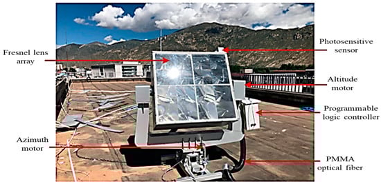
Figure 3.
A Fresnel lens-based optical fiber daylighting system.
4.1.2. Parabolic Dishes
Parabolic dishes use parabolic-shaped mirrors to concentrate light into a central receiver placed at the focal point of the dish, where the concentrated sunlight is directed. The parabolic shape of the dish ensures that the incoming light rays parallel to the dish’s axis are reflected toward this focal point, resulting in a highly concentrated beam of solar energy [50]. Sapia [51] used a parabolic dish made of aluminum for the proposed FOD system, which was also coated with a highly reflective material named Vegalux, and the collector efficiency reached 95% an example of Built prototype of an FOD system with four parabolic mirrors is shown in Figure 4 [51]. Dhanashri et al. [52] also used an aluminum parabolic dish in their study. The inner walls of the collector were not coated with any extra reflective materials, and the collector efficiency was shown to be 54%, which greatly suggests that increasing the reflectivity of the material used in the parabolic dishes is effective in achieving higher optical efficiencies [53].
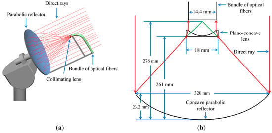
Figure 4.
(a,b) Built prototype of an FOD system with four parabolic mirrors.
4.2. Non-Imaging Fiber Optics Solar Energy Concentration Systems
Unlike microchip optics, solar concentrators can be non-imaging or soft optics (that is, with a large spot at the focal point). Well-designed non-imaging concentrating systems have quite a generous tolerance for positioning errors. For example, a parabolic cylinder concentrator can still function reasonably well in non-tracking mode, collecting sunlight even at a 45° misalignment to the sun. A non-imaging concentrator has an inexact focal point and does not produce the same image as the light sources [54,55,56]. The non-imaging concentrators are designed to work as passive tracking collectors. Fiber optics has been widely used for the non-imaging collection of sunlight and, therefore, for daylighting applications. For FODs that use imaging concentrators, a sequence that consists of at least two optical stages should be designed to achieve better overall transmission efficiencies. Compound parabolic collectors (CPCs) are non-imaging concentrators that were most likely coupled with FOD systems. CPCs reflect and concentrate sunlight into a receiver, unlike the traditional parabolic dishes, which focus sunlight onto a single point. CPCs are characterized by their unique shape, consisting of multiple parabolic sections. This design allows them to capture light over a wider acceptance angle and direct it toward one or more focal points along their focal planes [57,58]. Vu and Shin [59] designed an FOD system using a non-imaging concentrator consisting of an array of linear Fresnel lenses. The geometric concentration ratio of the system was designed at 100. The system had a high tolerance for the incident sunlight angle, which allowed the use of a single-axis sun-tracking system instead of a dual-axis sun-tracking system. The optical design of such a system resulted in lower capital and operating costs for the FOD system; however, the optical efficiency only reached 56.4%. Figure 5 shows the Ray path diagram of different solar concentrators.
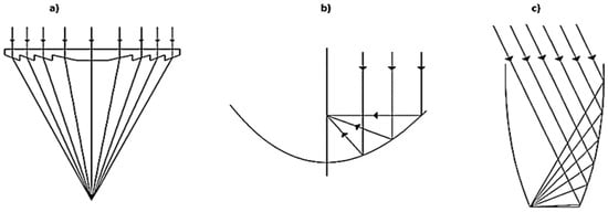
Figure 5.
Ray path diagram of different solar concentrators: (a) a Fresnel lens, (b) a parabolic concentrator, and (c) a compound parabolic concentrator [55].
4.3. Imaging vs. Non-Imaging Fiber Optics Solar Energy Concentration Systems
When comparing both types of collectors, we can see that the imaging collectors provide very intense, locally concentrated light due to their focusing ability, which is very advantageous in FOD systems. Two primary factors in fiber optics technology that affect light transmission are absorption and scattering [60,61]. Because of the absorption process, some light is lost, but if the light is intense, the material of the fiber optics system becomes saturated, which will make the material unable to absorb more light. On the other hand, non-imaging collectors can capture sunlight in a broader area, although not at the same high intensity as the imaging collectors and are less vulnerable to heat issues. Imaging collectors offer easier solutions for uniformity, adaptability to varying light conditions, and design flexibility but require higher net present value costs. Figure 6 illustrates the classification of the solar concentrators that are commonly used in FOD systems. The optical efficiency, which is defined as the ratio of the useful optical power reaching the receiver to the total incident solar power, is highly dependent on factors such as the incidence angle, the properties of the optical material, and optical losses (tracking, misalignment, slope errors, etc.). In most concentrators, the sensitivity of the optical efficiency to the incidence angle is investigated to predict the long-term energy yield of the system. Figure 7 shows the optical efficiency of the most common solar concentrators used in FOD systems as a function of the incidence angle. Figure 8 compares the efficiency and concentration ratios of different types of solar concentrators used in FOD systems.
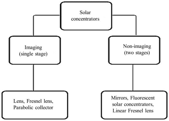
Figure 6.
Classification of solar concentrator used in FOD.
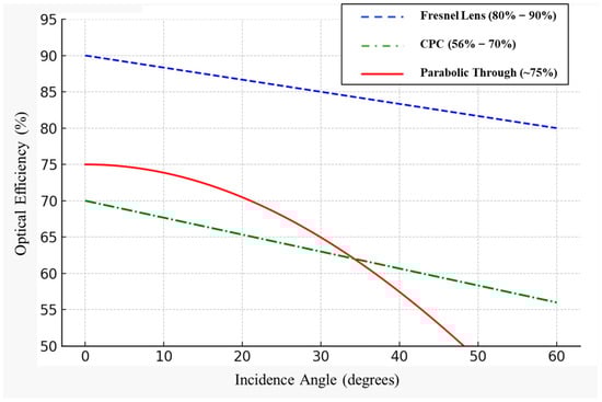
Figure 7.
Optical efficiency of common solar concentrators used in FOD systems with respect to the incidence angle [44,62,63].
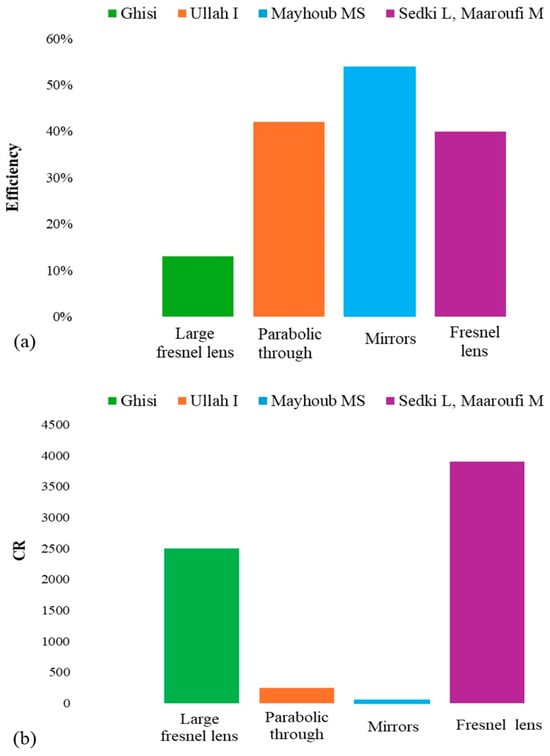
Figure 8.
(a) the recorded concentration ratios (CRs) of different FOD systems. and (b) Optical efficiency of different FOD systems [44,45,64,65].
5. Integration of Fiber Optics with Solar-Concentrating Systems
The optical components of the solar concentrator system have an important role in determining the optical efficiency of the entire system. Both hollow and arbitrary cross-section fibers can be geometrically designed using computational algorithms for specific applications such as guiding, concentrating, and diffusing light [66]. Dissimilar types of fibers can also be coaxially integrated for further improved efficiency and performance. Light concentrator systems based on optical fibers behave like a focus on the light source, reducing the intensity of the output while the diffusing fibers provide enhanced uniform light distribution. Although fiber optics and solar energy system research has rapidly evolved over the past decades, the combination of the two during the past few years has demonstrated their great potential for improving the performance of solar-concentrating systems and reducing costs. At present, many research groups worldwide are exploring optical fiber technology with solar-concentrating systems. This is primarily motivated by the advantageous features of optical fibers, such as low cost, mass production, low optical losses, and lightweight flexible structures, as well as the ability to maintain a highly concentrated intensity over a long distance. Viable technologies have emerged by replacing existing high-cost components in conventional designs, such as optical concentrating systems with optical fibers. A variety of approaches have been proposed and developed to integrate optical fiber-based technology into solar collectors. Research efforts are focused on modeling and characterizing solar fiber optics, designing and building solar concentrating systems based on optical fibers, and assembling and testing the combined system. The development of fiber optic-based solar energy systems is still in its embryonic stage, as evidenced by only a few built prototypes or proposed proof-of-concept projects. However, optical fiber technology is promising for solar energy systems, paving the avenue for greater energy savings and better performance in building applications [67].
Fiber optic daylighting systems have a wide range of applications in various domains [68]. For example, one of the first systems made in the 1970s was the Himawari by Professor Kei Mori. This system consisted mainly of a solar collector and quartz–glass optical fibers [69]. Daylighting system-based fiber optics are designed to bring natural daylight into areas that are typically dark or have limited access to windows. Furthermore, such FOD systems can be used in buildings for energy-saving purposes and to withstand the lack of daylight sources [70]. They developed an underground system with high solar flux to provide daylighting. This system uses a Fresnel lens and three heat protection measures, namely an infrared filter, a homogenizer, and fiber facet polishing. The polishing technique was used to remove dark spots at the end of the PMMA fiber, which are the result of dust and the interaction of light with the micro-grooves on the surface of the PMMA optical fiber. This involves reflection and refraction, which will cause the fiber to overheat. Ullah and Shin [71] developed a fiber optic-based daylight system for multi-floor buildings to provide uniform lighting throughout the different levels, Vu and Shin [12] combined a fiber optic daylight system with solar panels, allowing the system to harness solar energy during the day and use it to power the lighting at night. Vu and Shin explored the potential of energy savings and improved lighting quality by combining fiber optic daylight systems powered by solar energy with artificial lighting systems. They investigated the performance of a hybrid daylighting system by using an infrared filter to bounce off the non-visible (near and infrared light) fibers, while only the most effective and visible light is transmitted to the fibers. Single-junction solar cells were used to generate enough energy for the grid-integrated system to be supplied during deficient hours during the day and night. The results showed that the system can achieve 63.8% optical efficiency. The workflow process of this system is shown in Figure 9. Additionally, Qin et al. [36] made an optical fiber daylighting system in a highway tunnel in China, as shown in Figure 10. Another approach where FOD systems are useful is in windowless rooms. Tsangrassoulis et al. [69] used a heliostat equipped with a concentrating Fresnel lens to transmit light into a windowless room through a large-core liquid optic fiber. Another approach by SCLAB, named the Sunflowers project, employs mass-producible plastic aspheric lenses coupled with optical fibers to collect and transport sunlight for interior illumination the system is shown in Figure 11 [72]. Implementing this type of system can help in transmitting natural light into spaces with no windows, which will result in several advantages, such as energy savings and health benefits. A Revit sketch demonstrating how the FOD system may be installed is shown in Figure 12. Fiber optic daylighting systems have the potential to be integrated with solar energy technologies, especially the concentrating systems since they can provide more uniform sunlight beams to the optic fibers, ensuring better fitting to their acceptance angles at higher sources of power. This integration enhances the overall efficiency of the daylighting system by utilizing solar energy to power the lighting systems. Figure 13 shows Different working arrangements of FOD systems.
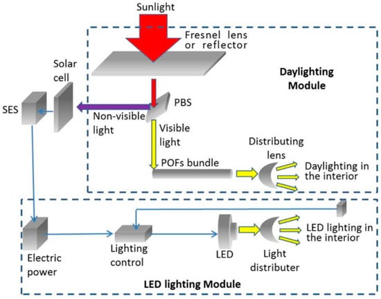
Figure 9.
Example of building-integrated fiber optics applications [12].
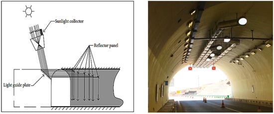
Figure 10.
Schematic design of a solar optical fiber and light pipe installation in the plan zone of Huashuyan Tunnel in China [36].
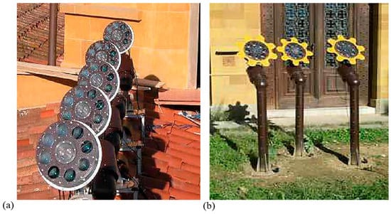
Figure 11.
(a): The Sunflower project in Italy; (a) system installed on a museum roof; and (b) a system installed in the museum’s garden.
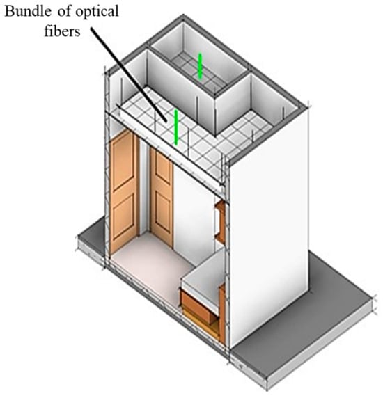
Figure 12.
FOD structure in a windowless room.
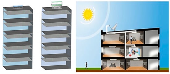
Figure 13.
Different working arrangements of FOD systems [36,71].
6. Performance Analysis of FOD Systems
Different materials are used for fiber optics in daylighting systems, such as plastic, silica, glass, quartz, polymer, and liquids. The most common optical fibers are silica glass optical fibers (SOFs) and plastic optical fibers (POFs). Ideally, SOFs are the best for daylight systems [73,74]; however, due to the high cost of SOFs, POFs are most frequently used for a more cost-effective BIFO solution. Alternatively, the two are coupled together using a gel-matching interface to release the heat more effectively at the inlet aperture of the bundle, and the POF-based fibers can be used downstream to reduce the capital cost of the system and to transmit the light over longer distances. Table 2 shows a comprehensive comparison between the different optical fiber-based daylight systems and shows the range of illumination outputs that the FOD systems achieved. Table 2 shows different FOD systems for different applications, all with the same goal of bringing daylight into interior spaces.
Table 2.
Performance of different daylight systems for various applications using fiber optics.
7. Recent Developments in Optical Materials and the Market Value of Fiber Optic Daylighting Systems
7.1. Recent Development in Fiber Optic Materials
Recent developments in optical materials and designs for fiber optic daylighting systems have greatly improved their efficiency and performance. For instance, advancements have been employed to improve the spectral response of different materials. Nanotechnology allows for the optical properties of the new fiber optic materials to be enhanced. Nanomaterials such as quantum dots, nanoparticles, and nanostructured coatings have been used to improve the properties of the core and cladding of optical fibers. These materials can enhance light transmission efficiency, reduce optical loss, and make fibers more flexible. Furthermore, nanotechnology enables the development of coatings with nanometer-scale structures that can effectively reduce light scattering and minimize signal degradation due to imperfections on the fiber’s surface. Incorporating nanostructures into the glass or silica used in optical fibers can enhance light propagation and reduce the attenuation (signal loss) of light as it travels through the fiber. These enhanced nanostructured materials have allowed daylighting systems to become more flexible and record greatly improved overall transmission efficiencies in a large number of applications. The most often used materials are polymethyl methacrylate and silica glass [73]. The principle for designing daylight systems is biased toward geometric optics because it provides a clear framework for understanding how light behaves when it interacts with various materials and surfaces, focusing on the optical characteristics of the refraction, reflection, transmission, and absorption of incidental light [82]. Polymethyl methacrylate is a commonly used material for plastic optical fibers in daylighting systems due to its high transmittance and low cost. However, PMMA presents several challenges, as revealed by Liu et al. [80], who found that light leakage significantly reduces the transmission efficiency through PMMA fiber optics, particularly at incident angles greater than 13°. Yang et al. [83] attempted to overcome the issue of overheating by using an infrared filter upstream of the fiber optics cable and a flux homogenizer, and by polishing the facets of the fibers. Li et al. [10] developed an experimental system using large Fresnel lenses, a hot mirror, and a homogenizer to protect the PMMA fibers from high temperatures. The system was tested in an underground passage and reached an illumination flux of 360 lux, with optical efficiency ranging between 11–13%. Silica fibers could turn out to be better light transmission media than plastic fibers [11,74], as they present lower losses and can handle higher temperatures. Most experiments in daylight systems use PMMA fiber optics, while a very interesting approach by Ullah [71], who combined POF and SOF fiber bundles using a matching gel shown in Figure 14, yielded an increase in efficiency of 23% over a system that only used PMMA. This improvement in efficiency can be attributed to the different optical properties of POFs and SOFs. Specifically, POFs typically offer flexibility and lower costs, while SOFs provide higher transmission efficiencies and greater durability under exposure to sunlight. By integrating these two types of fibers, the system not only achieves higher efficiency in light transmission but also becomes more cost-effective over time. The combination leverages the strengths of each fiber type, optimizing the overall performance and cost of the daylighting system.
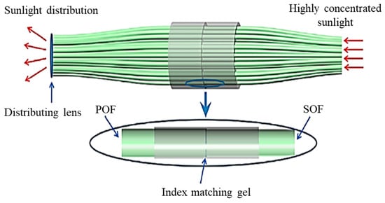
Figure 14.
Ullah’s approach combines POFs and SOFs [71].
Table 2 lists the main performance indicators (illumination and transmission efficiency) of different experimental and numerical studies that investigated the feasibility and design optimization of daylighting systems based on fiber optics. Table 3 and Table 4 recapitulate the typical geometrical dimensions of POFs and SOFs, respectively, along with their numerical aperture and optical attenuation. Table 5 demonstrates the superior quality of SOFs in terms of handling high temperatures and thermal stresses.
Table 3.
Reference dimensions and optical characteristics of POFs.
Table 4.
Reference dimensions and optical characteristics of SOFs.
Table 5.
Comparison of material properties for fiber optics.
Table 6 illustrates the comparison of the spectral transmittance across UV/visible/IR ranges between PMMA and silica fiber optics. It is worth noting that silica fibers generally have superior performance in UV and IR transmission, making them more versatile for a wide range of optical applications. However, PMMA fibers are still excellent for applications where visible light transmission is needed and where cost and flexibility are important considerations.
Table 6.
Comparison of visible light transmission through PMMA and silica fiber optics.
7.2. Recent Developments in the Market Value of Fiber Optics Lighting
Recent reports from sources such as the U.S. Energy Department show the compound annual growth rate (CAGR) in the fiber optics market, which was above 10% in 2022. The fiber optic lighting market was valued at USD 2.8 billion and is expected to reach USD 4.8 billion by 2030, growing at a CAGR of about 7%. A visual demonstration of this market growth is shown in Figure 15.
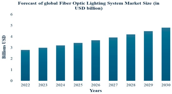
Figure 15.
Expected FOD market value growth by 2030 in USD (billions).
8. Benefits and Challenges of Fiber Optic Solar Energy Concentration
8.1. Benefits of Fiber Optic Solar Energy Concentration
The unique properties of optical fibers could be utilized to develop a new type of solar energy-supplying system. Up to now, few attempts have been made to implement this kind of system in building applications. Optical fibers could efficiently transfer solar energy when it is focused, absorbed at the core’s portion, and distributed afterward along the fiber by surface modes. Of course, there are advantages and challenges to using optical fibers instead of conventional integrated grid lighting systems. The first points to be considered are the benefits of incorporating optical fibers into solar-concentrating systems. An optical fiber, either in the form of a bundle or a single fiber, can collect light due to its very large acceptance angles, high concentration factors, and short working focal lengths. The insertion of a tight-focusing optical fiber allows the expandability of commercial parabolic systems by several kilowatts [87]. The integration of optic fibers with solar-concentrating collectors would be very effective in ensuring higher levels of safety and reliability. Safety comes from the absence of toxic gases or hazardous fluid leaks. Table 7 lists concisely the beneficial impacts of the fiber optic daylighting systems.
Table 7.
The beneficial impacts of fiber optic daylighting systems.
8.2. Challenges of Fiber Optic Solar Energy Concentration
Fibers have certain drawbacks, even if the system is composed of bundles of non-relocatable fibers. Besides the high losses of optic fibers, the control and adjustment of each fiber would be heavy, expensive, and complicated work. There are also technical challenges to storing big bundles, requiring big and bulky devices, as well as installation in facilities on an hourly and daily daylight basis. Furthermore, the daily mode would not operate on stormy or cloudy days, and a large fraction of the installed energy would be wasted [92]. In FOD systems, heat is unwanted due to the temperature sensitivity of the fiber optics. Several approaches can be used to prevent overheating, such as using cold/hot mirrors, converging lenses, and filters. All these solutions can be used in combination or individually to overcome this problem. Cold and hot mirrors are spectrally selective surfaces that serve as reflective components. Cold mirrors selectively reflect visible light while allowing infrared radiation to pass through [93]. They used eight-faceted cold mirrors to reflect the visible wavelength radiation into each fiber; cold mirrors can typically reflect 95–97% of visible light (450–700 nm), while a hot mirror reflects infrared and transmits visible light. Li et al. [10] and Vu et al. [12] both used hot mirrors in their investigated FOD systems. Hot mirrors can reflect 90% of IR light, which will significantly cut the thermal load without affecting the visible output greatly [94]. While a comparative study has not yet been conducted, hot mirrors are generally better since they reflect infrared, which is unwanted and leads to only visible light being able to get through, which is what is used mainly for FOD illumination [46]. Converging lenses such as concave lenses can be used as a beam splitter within the selective wavelength range. When polychromatic sunlight is crossed through a converging lens, the focal point will vary accordingly, and removing some unwanted parts of the sunlight would be very effective. For instance, Ullah et al. [71] and Maatallah et al. [95] have investigated and elaborated on the impact of such a technique on the performance of their designed FOD systems. The obtained results of these two studies demonstrated that the converging lenses showed a consequential impact on increasing the uniformity of light, which can indeed contribute to better temperature management. Figure 16 shows Hot mirrors that are used as infrared filters mounted in an FOD system.
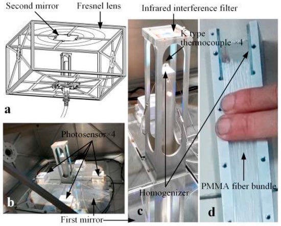
Figure 16.
Hot mirrors are used as infrared filters mounted in an FOD system. (a) 3D structure of the optic system. (b) Inner structure. (c) Filter and homogenizer. (d) PMMA fiber bundle [10].
Another undesirable side effect of building-integrated fiber optics (BIFO) is the heat generated by the fibers, which are most likely made up of PMMA inside building spaces. Munaaim et al. [35] studied the thermal effect of FOD on buildings in a tropical region, where it was found that FOD systems can increase indoor temperatures by 0.8 °C. Filters are spectral-sensitive devices that can be effectively used in FOD systems to avoid the overheating and burning of optic fibers, especially plastic-based optic fibers (POFs). The filters are different than hot mirrors since they absorb infrared radiation instead of reflecting it. IR and visible light wavelengths range between 740–1100 nm and 400–700 nm, respectively [82]. Visible light is the most wanted portion of the sun’s spectrum, while IR radiation is unwanted. Therefore, it is recommended to filter out the latter before it reaches the inlet aperture of the optical fibers. Zazoum et al. [96] used IR filters to protect POF cables from overheating. The experimental results indicate that the IR filter can safeguard the thermoplastic optical fiber from heat damage without reducing the output illuminance, potentially prolonging the lifespan of the optical fibers [97]. When comparing hot mirrors and homogenizers for heat mitigation in fiber optic daylight systems, it is essential to consider their optical efficiency and temperature trade-offs. In effect, hot mirrors block specific heat (IR) sources by reflecting IR radiation away from the fiber optics bundle without affecting the visible light being transmitted through the fibers. The reflection of IR radiation decreases the thermal load and the temperature of the optical fiber. The extent of the temperature reduction depends on the amount of IR energy the mirror can reflect and how much IR energy is in the system. On the other hand, homogenizers reduce localized heating by spreading the light over a larger area. However, they do not directly block or reflect IR radiation like hot mirrors. Instead, they modify the light’s spatial intensity distribution to ensure that heat is more evenly distributed. In terms of optical transmission, the hot mirrors typically transmit visible light (approximately 400–700 nm) very efficiently, often above 90%; however, depending on the design and material of the homogenizer, transmission can vary. Generally, the optical efficiency may range between 80–95% for certain homogenizer types (e.g., diffusers and integrating rods). Homogenizers distribute light over a larger area, which can reduce localized temperature spikes but does not eliminate the overall heat generated by the system. The system may not experience a significant overall temperature drop, but hotspots can be mitigated, preventing extreme temperature rises in concentrated areas. Table 8 summarizes the key differences between hot mirrors and homogenizers.
Table 8.
Trade-offs between the features of hot mirrors and homogenizers.
Several implementations and designs showed the effectiveness of FOD systems in daylighting in buildings and in transmitting light from long distances from the source. For instance, Song et al. [19] achieved about 25% light transmission at a distance of 10 m, reaching an average illumination of 122 lux over a 36 m2 area [97]. Chong et al. reported an output luminous flux of over 500 lux using a solar collection area of 0.2 m2 and a collimating secondary lens at an optical concentration level of 66.6 suns [82]. Sreelakshmi and Ramamurthy [98] concluded that FOD systems have matured to provide comfortable lighting levels while managing heat. Figure 17 shows A built FOD prototype using a Plano concave lens.
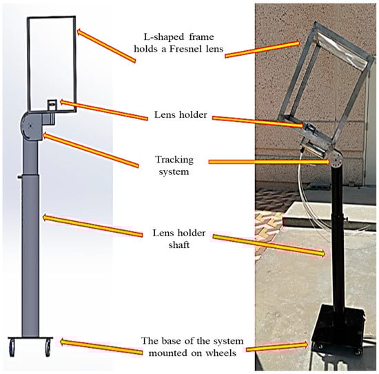
Figure 17.
A built prototype using a Plano concave lens [95].
9. Comparison Between FODs and Traditional Lighting and Daylight Systems
Comparing the fiber optic daylighting systems with other daylight technologies such as light pipes and Heliostat, it is observed that light pipes can be cost-effective and easy to install but have very limited luminous flux outputs at long distances [99]. Furthermore, Heliostats are efficient in capturing a high intensity of light for large spaces, but they require specialized maintenance, which adds more technological complexity [99]. The main advantages of FOD systems are efficient light distribution and the superiority of transporting light over longer distances. On the other hand, the optical efficiency of the other daylight technologies depends significantly on the light path and the design of the system. A report by the United States Department of Energy Efficiency and Renewable Energy showed that traditional bulbs produce around 15 lumens per watt (lm/w), fluorescent lamps produce about 75 lm/w, and LEDs may reach 180 lm/w. However, FOD systems can deliver 200 lm/w of visible light, which means that a FOD system can provide much more light output per watt than conventional lighting systems. FOD systems can also reduce a building’s light energy use. In [100], annual lighting energy savings of 19% were reported in high-latitude regions in Uppsala and Sweden, as well as savings of 46% in southern European cities. Energy savings may vary when replacing conventional lighting with FOD. In effect, replacing inefficient bulbs with FOD will lead to larger gains than replacing already efficient LEDs. Lv et al. [37] reported that a hybrid FOD became cheaper than a traditional fluorescent lighting system after 7 years of use. This accumulation over time offsets the higher initial investment of the FOD system. Compared to traditional grid-integrated lighting solutions, FOD also has the advantages of heat generation reduction and enhanced light quality. The only two limitations of FOD systems are the higher initial investment and the performance sensitivity to sunlight availability. Table 9 summarizes the comparison between key features of FOD systems and grid-integrated lighting solutions.
Table 9.
Comparative analysis between FOD and traditional grid-integrated lighting solutions.
10. Conclusions and Recommendations
Daylight systems using fiber optics (FOD) present a promising, innovative approach to harnessing solar energy and addressing various environmental and energy challenges. This review systemically examines the essential requirements, current state, and performance of FOD systems. The main findings of the present review paper can be summarized as follows:
- An efficient FOD system necessitates an optimized combination of fiber optics, solar collectors, and light diffusers. The optimal functionality and operation of such a system depend on careful and optimum optical design and control of the energy flux through it for better light quality (brightness, luminous efficacy, uniformity, etc.) and energy savings.
- Parabolic trough-based systems have been found to exhibit superior optical efficiency among various solar collection techniques, primarily due to their linear alignment, which can minimize interstitial optical losses. Further, the application of double linear Fresnel lenses has been found to achieve comparable optical efficiency, rendering it another promising approach.
- The performance of optical fibers varies significantly depending on the materials. Silica glass-based fibers are the most efficient because they capture light in a wide spectrum range, handle higher thermal stress, and present minimum optical dispersion or attenuation losses.
- It was also revealed that although plastic-based fibers have lower performance compared to silica–glass-based fibers, they offer advantages such as ease of installation, lower costs, and flexibility, especially when combined with silica–glass-based fibers.
- FOD systems utilize various technologies such as parabolic dishes and Fresnel lenses to optimize light collection. PMMA fibers are suitable for short distances and low-intensity applications, while silica is better for long distances and higher temperatures. FOD systems are applicable in a wide range of residential, commercial, and underground applications. When using PMMA, optimal performance can be reached by maintaining the temperature between 70 and 80 degrees Celsius unless cooling or silica is used. Using technologies such as filters or mirrors is critical for optimizing illumination and system longevity. This review highlighted that the optical transmission efficiency of FOD systems is influenced by several factors, such as absorption, geometrical losses, and scattering losses.
- This review also revealed that simulations have been predominantly employed for assessing the performance of FOD systems, emphasizing the pressing need for long-term outdoor data collection and experimental validation using real-world data.
- Despite the recent advancements in FOD systems, there exist several challenges limiting their widespread adoption. Key challenges in this regard include efficiency optimization, long-term performance studies, material innovations and cost constraints, standardization, and scalability.
- This review’s findings provide a solid foundation for future research studies aimed at optimizing the performance, real-world applicability, and economic viability of FOD technologies, as well as their integration with smart building systems.
- Future research should focus on developing hybrid systems that combine FOD technology with energy storage solutions, such as batteries, to provide a reliable and continuous light source even during periods of low sunlight, thereby increasing the practicality and adoption of FOD systems in diverse settings.
Author Contributions
Conceptualization, T.M., M.A. and S.A.; methodology, T.M., M.A., F.W., A.J. and S.A.; software, T.M., M.A., F.W., A.J. and S.A.; validation, T.M., M.A., F.W. and S.A.; formal analysis, T.M., M.A. and S.A.; investigation, T.M., M.A. and S.A.; resources, T.M., M.A. and S.A.; data curation, T.M., M.A. and S.A.; writing—original draft preparation, T.M.; writing—review and editing, T.M., M.A., F.W., A.J. and S.A.; visualization, T.M., M.A., F.W., A.J. and S.A.; supervision, T.M.; project administration, T.M., M.A. and S.A.; funding acquisition, T.M. All authors have read and agreed to the published version of the manuscript.
Funding
This research received no external funding.
Acknowledgments
The authors would like to acknowledge the support provided by Imam Abdulrahman Bin Faisal University (IAU), Dammam, Saudi Arabia.
Conflicts of Interest
The authors declare no conflicts of interest.
References
- Nikolaidis, P. Solar Energy Harnessing Technologies towards De-Carbonization: A Systematic Review of Processes and Systems. Energies 2023, 16, 6153. [Google Scholar] [CrossRef]
- Rabaia, M.K.H.; Abdelkareem, M.A.; Sayed, E.T.; Elsaid, K.; Chae, K.-J.; Wilberforce, T.; Olabi, A. Environmental impacts of solar energy systems: A review. Sci. Total Environ. 2021, 754, 141989. [Google Scholar] [CrossRef] [PubMed]
- Boukdir, Y.; El Omari, H. Novel high-precision low-cost dual-axis sun tracker based on three light sensors. Heliyon 2022, 8, e12412. [Google Scholar] [CrossRef]
- Pendão, C.; Silva, I. Optical Fiber Sensors and Sensing Networks: Overview of the Main Principles and Applications. Sensors 2022, 22, 7554. [Google Scholar] [CrossRef] [PubMed]
- Zanoon, N.I. The Phenomenon of Total Internal Reflection and Acceleration of Light in Fiber Optics. Int. J. Comput. Appl. 2014, 107, 19–24. [Google Scholar] [CrossRef]
- Štochl, N.; Vychytil, J.; Hájek, P. Illumination of Interior Spaces through Structures Made of Unified Slabs of High-Performance Light-Transmitting Concrete with Embedded Optical Fibers. Materials 2023, 16, 3142. [Google Scholar] [CrossRef]
- Baniya, H.B. Fiber Technology and Its Application in the Modern Society. Stem Cell Res. Int. 2022, 5, 01–03. [Google Scholar] [CrossRef]
- Han, H.J.; Riffat, S.B.; Lim, S.H.; Oh, S.J. Fiber optic solar lighting: Functional competitiveness and potential. Sol. Energy 2013, 94, 86–101. [Google Scholar] [CrossRef]
- Ullah, I.; Whang, A. Development of Optical Fiber-Based Daylighting System and Its Comparison. Energies 2015, 8, 7185–7201. [Google Scholar] [CrossRef]
- Li, L.; Wang, J.; Yang, Z.; Luo, G.; Tong, K.; Zhao, J.; Song, J. An optical fiber daylighting system with large Fresnel lens. Energy Procedia 2018, 152, 342–347. [Google Scholar] [CrossRef]
- Pham, T.; Vu, N.; Shin, S. Daylighting System Based on Novel Design of Linear Fresnel lens. Buildings 2017, 7, 92. [Google Scholar] [CrossRef]
- Vu, N.H.; Shin, S. Optical Fiber Daylighting System Combined with LED Lighting and CPV based on Stepped Thickness Waveguide for Indoor Lighting. J. Opt. Soc. Korea 2016, 20, 488–499. [Google Scholar] [CrossRef]
- Singh, S.; Thussu, M.; Ahmad, A. Technology Interventions of Daylight for Deep Plan Building. Int. J. Res. Appl. Sci. Eng. Technol. 2023, 11, 2145–2151. [Google Scholar] [CrossRef]
- Dutta, M. Maximizing the Benefits of Daylight in Residential Design and Construction: A Review of Modern Homes and Villas. Stud. Art Archit. 2023, 2, 16–20. [Google Scholar] [CrossRef]
- Tabadkani, A.; Roetzel, A.; Li, H.X.; Tsangrassoulis, A. Daylight in Buildings and Visual Comfort Evaluation: The Advantages and Limitations. J. Daylight. 2021, 8, 181–203. [Google Scholar] [CrossRef]
- Fonseca, R.W.D.; Pereira, F.O.R.; Queiroz, E.A.; Stockhausenn, B. The influence of latitude and sky conditions on daylight harvesting inbuildings. Ambiente Construído 2023, 23, 63–81. [Google Scholar] [CrossRef]
- Bellia, L.; Fragliasso, F.; Riccio, G. Daylight fluctuations effect on the functioning of different daylight-linked control systems. Build. Environ. 2018, 135, 162–193. [Google Scholar] [CrossRef]
- Lam, J.C.; Li, D.H.W. Luminous efficacy of daylight under different sky conditions. Energy Convers. Manag. 1996, 37, 1703–1711. [Google Scholar] [CrossRef]
- Song, J.; Luo, N.; Wang, W. Configuration of daylighting system via fibers and experiments of concentrated sunlight transmission. In 2013 International Conference on Materials for Renewable Energy and Environment; IEEE: Chengdu, China, 2013; pp. 128–132. [Google Scholar] [CrossRef]
- Jeunhomme, L.B. Single-Mode Fiber Optics: Principles and Applications, 1st ed.; Routledge: Abingdon, UK, 2019. [Google Scholar] [CrossRef]
- Koike, Y.; Koike, K. Optical Fibers. In Polymer Science: A Comprehensive Reference; Elsevier: Amsterdam, The Netherlands, 2012; pp. 283–304. [Google Scholar] [CrossRef]
- Salih, A.R. Design of Step-Index Multimode Optical Fiber. J. Phys. Conf. Ser. 2021, 1879, 032074. [Google Scholar] [CrossRef]
- Tricker, R. Optical Fibres in Power Systems. In Electrical Engineer’s Reference Book; Elsevier: Amsterdam, The Netherlands, 2003; pp. 37-1–37-17. [Google Scholar] [CrossRef]
- Ohno, Y.; Goodman, T.; Blattner, P.; Shitomi, H.; Sperling, A.; Schanda, J.; Zwinkels, J.C. CIE 018:2019 The Basis of Physical Photometry, 3rd ed.; International Commission of Illumination: Vienna, Austria, 2019. [Google Scholar]
- Wang, H. Optical properties of a graded-index fiber: The diffraction measurement determination. Opt. Mater. 1996, 5, 153–158. [Google Scholar] [CrossRef]
- Lara, A.P.; Roy, S.; Agrawal, G.P. Modeling of High-Power Graded-Index Fiber Amplifiers. Photonics 2024, 11, 737. [Google Scholar] [CrossRef]
- Nardelli, A.; Deuschle, E.; de Azevedo, L.D.; Pessoa, J.L.N.; Ghisi, E. Assessment of Light Emitting Diodes Technology for General Lighting: A Critical Review. Renew. Sustain. Energy Rev. 2017, 75, 368–379. [Google Scholar] [CrossRef]
- Munaaim, M.A.C.; Al-Obaidi, K.M.; Ismail, M.R.; Rahman, A.M.A. A review study on the application of the fibre optic daylighting system in Malaysian buildings. Int. J. Sustain. Build. Technol. Urban Dev. 2014, 5, 146–158. [Google Scholar] [CrossRef]
- Nugrahani, E.F.; Birahmatika, R.A.; Pratiwi, E.W.; K, S. Design of Solar Transmission System using Fiber Optic for Indoor Lighting. KnE Energy 2015, 2, 59–70. [Google Scholar] [CrossRef]
- Wallhead, I.; Jiménez, T.M.; Ortiz, J.V.G.; Toledo, I.G.; Toledo, C.G. Design of an efficient Fresnel-type lens utilizing double total internal reflection for solar energy collection. Opt. Express 2012, 20, A1005–A1010. [Google Scholar] [CrossRef]
- Sterhov, A.I.; Petrov, K.A.; Loshkarev, I.Y. Engineering design of solar concentrator for transporting sunlight through optical fiber. J. Phys. Conf. Ser. 2019, 1353, 012004. [Google Scholar] [CrossRef]
- Sansoni, P.; Fontani, D.; Francini, F.; Mercatelli, L.; Jafrancesco, D.; Sani, E.; Ferruzzi, D. Internal Lighting by Solar Collectors and Optical Fibres. In Solar Collectors and Panels, Theory and Applications; Manyala, R., Ed.; Sciyo: Rijeka, Croatia, 2010. [Google Scholar] [CrossRef]
- Aslian, A.; Asli, B.H.S.; Tan, C.J.; Adikan, F.R.M.; Toloei, A. Design and Analysis of an Optical Coupler for Concentrated Solar Light Using Optical Fibers in Residential Buildings. Int. J. Photoenergy 2016, 2016, 3176052. [Google Scholar] [CrossRef]
- Vu, N.-H.; Pham, T.-T.; Shin, S. Modified optical fiber daylighting system with sunlight transportation in free space. Opt. Express 2016, 24, A1528–A1545. [Google Scholar] [CrossRef]
- Munaaim, M.; Al-Obaidi, K.; Ismail, M.; Rahman, A. Empirical Evaluation of the Effect of Heat Gain from Fiber Optic Daylighting System on Tropical Building Interiors. Sustainability 2014, 6, 9231–9243. [Google Scholar] [CrossRef]
- Qin, X.; Zhang, X.; Qi, S.; Han, H. Design of Solar Optical Fiber Lighting System for Enhanced Lighting in Highway Tunnel Threshold Zone: A Case Study of Huashuyan Tunnel in China. Int. J. Photoenergy 2015, 2015, 471364. [Google Scholar] [CrossRef]
- Lv, Y.; Xia, L.; Yan, J.; Bi, J. Design of a Hybrid Fiber Optic Daylighting and PV Solar Lighting System. Energy Procedia 2018, 145, 586–591. [Google Scholar] [CrossRef]
- Song, J.; Zhu, Y.; Jin, Z.; Yang, Y. Daylighting system via fibers based on two-stage sun-tracking model. Sol. Energy 2014, 108, 331–339. [Google Scholar] [CrossRef]
- Vu, N.H.; Shin, S. Flat Optical Fiber Daylighting System with Lateral Displacement Sun-Tracking Mechanism for Indoor Lighting. Energies 2017, 10, 1679. [Google Scholar] [CrossRef]
- He, K.; Chen, Z.; Zhong, S.; Qian, Y.; Liu, H.; Yin, J.; Zhou, B. A solar fiber daylighting system without tracking component. Sol. Energy 2019, 194, 461–470. [Google Scholar] [CrossRef]
- Kharchenko, V.; Vasant, P. (Eds.) Advances in Computer and Electrical Engineering. In Renewable Energy and Power Supply Challenges for Rural Regions; IGI Global: Hershey, PA, USA, 2019. [Google Scholar] [CrossRef]
- Bassett, I.M.; Welford, W.T.; Winston, R. III Nonimaging Optics for Flux Concentration. In Progress in Optics; Elsevier: Amsterdam, The Netherlands, 1989; Volume 27, pp. 161–226. [Google Scholar] [CrossRef]
- De Boer, D.K.G.; Haenen, L. Extraction optics for high lumen density sources. J. Eur. Opt. Soc.-Rapid Publ. 2019, 15, 8. [Google Scholar] [CrossRef]
- Ullah, I. Fiber-based daylighting system using trough collector for uniform illumination. Sol. Energy 2020, 196, 484–493. [Google Scholar] [CrossRef]
- Sedki, L.; Maaroufi, M. Design of parabolic solar daylighting systems based on fiber optic wires: A new heat filtering device. Energy Build. 2017, 152, 434–441. [Google Scholar] [CrossRef]
- Qandil, H.; Zhao, W. Design and Evaluation of the Fresnel-Lens Based Solar Concentrator System Through a Statistical-Algorithmic Approach. In Volume 8B: Heat Transfer and Thermal Engineering; American Society of Mechanical Engineers: Pittsburgh, PA, USA, 2018; p. V08BT10A023. [Google Scholar] [CrossRef]
- Da Rosa, A.V.; Ordóñez, J.C. Solar Radiation. In Fundamentals of Renewable Energy Processes; Elsevier: Amsterdam, The Netherlands, 2022; pp. 519–576. [Google Scholar] [CrossRef]
- Iqbal, W.; Ullah, I.; Shin, S. Optical Developments in Concentrator Photovoltaic Systems—A Review. Sustainability 2023, 15, 10554. [Google Scholar] [CrossRef]
- Tripanagnostopoulos, Y.; Siabekou, C.; Tonui, J.K. The Fresnel lens concept for solar control of buildings. Sol. Energy 2007, 81, 661–675. [Google Scholar] [CrossRef]
- Dincer, I.; Bicer, Y. 4.23 Solar Thermochemical Energy Conversion. In Comprehensive Energy Systems; Elsevier: Amsterdam, The Netherlands, 2018; pp. 895–946. [Google Scholar] [CrossRef]
- Sapia, C. Daylighting in buildings: Developments of sunlight addressing by optical fiber. Sol. Energy 2013, 89, 113–121. [Google Scholar] [CrossRef]
- Butale, M.D.M.; Bagi, M.D.J.; Gurav, M.V. Design and Development of Fiber-Optic Solar Energy Concentration and Transmission Day-Lighting System. Int. Res. J. Eng. Technol. 2021, 8, 2113–2115. [Google Scholar]
- Auti, A.B.; Pangavane, D.R.; Singh, T.P.; Sapre, M.; Warke, A.S. Study on Reflector Material Optimization of a Parabolic Solar Concentrator. In Power Electronics and Renewable Energy Systems; Kamalakannan, C., Suresh, L.P., Dash, S.S., Panigrahi, B.K., Eds.; Lecture Notes in Electrical Engineering; Springer: New Delhi, India, 2015; Volume 326, pp. 275–284. [Google Scholar] [CrossRef]
- O’Gallagher, J.; Winston, R. Applications of maximally concentrating optics for solar energy collection. AIP Conf. Proc. 1985, 135, 448–471. [Google Scholar] [CrossRef]
- Freier, D.; Ramirez-Iniguez, R.; Jafry, T.; Muhammad-Sukki, F.; Gamio, C. A review of optical concentrators for portable solar photovoltaic systems for developing countries. Renew. Sustain. Energy Rev. 2018, 90, 957–968. [Google Scholar] [CrossRef]
- Kalogirou, S.A. Solar Energy Collectors. In Solar Energy Engineering; Elsevier: Amsterdam, The Netherlands, 2014; pp. 125–220. [Google Scholar] [CrossRef]
- Bellos, E.; Korres, D.N.; Tzivanidis, C. Investigation of a Compound Parabolic Collector with a Flat Glazing. Sustainability 2023, 15, 4347. [Google Scholar] [CrossRef]
- Jacobsen, A.; Neuroth, N.; Reitmayer, F. Absorption and Scattering Losses in Glasses and Fibers for Light Guidance. J. Am. Ceram. Soc. 1971, 54, 186–187. [Google Scholar] [CrossRef]
- Vu, N.H.; Shin, S. Development of daylighting systems with non-imaging concentrator. In Proceedings of the SPIE Optical Engineering + Applications, San Diego, CA, USA, 9–13 August 2015; p. 95720P. [Google Scholar] [CrossRef]
- Rani, N.; Dhayal, S.S.; Vinita, V. Investigating Impact of Attenuation Over Fiber Optic Communication. In Proceedings of the 2022 4th International Conference on Advances in Computing, Communication Control and Networking (ICAC3N), Greater Noida, India, 16–17 December 2022; IEEE: Greater Noida, India, 2022; pp. 1842–1848. [Google Scholar] [CrossRef]
- Wiesenfarth, M.; Steiner, M.; Wolf, J.; Schmidt, T.; Bett, A.W. Investigation of different Fresnel lens designs and methods to determine the optical efficiency. In Proceedings of the 3rd International Conference on Theoretical and Applied Physics 2013 (ICTAP 2013), Malang, East Java, Indonesia, 10–11 October 2013; pp. 97–101. [Google Scholar] [CrossRef]
- Indira, S.S.; Vaithilingam, C.A.; Sivasubramanian, R.; Chong, K.-K.; Saidur, R.; Narasingamurthi, K. Optical performance of a hybrid compound parabolic concentrator and parabolic trough concentrator system for dual concentration. Sustain. Energy Technol. Assess. 2021, 47, 101538. [Google Scholar] [CrossRef]
- Ghodbane, M.; Boumeddane, B.; Hussain, F.; Zhar, R.; Lahrech, K.; Bhatti, J.; Zhang, B.; Yassin, H.; Silva, C.L.D.; Barbón, A. Evaluation of the design and optical errors for a parabolic trough collector field in an Algerian desert region: Gassi-Touil as a study area. Energy Rep. 2022, 8, 15326–15337. [Google Scholar] [CrossRef]
- Mayhoub, M.S. Innovative daylighting systems’ challenges: A critical study. Energy Build. 2014, 80, 394–405. [Google Scholar] [CrossRef]
- Ghisi, E.; Tinker, J.A. Evaluating the potential for energy savings on lighting by integrating fibre optics in buildings. Build. Environ. 2006, 41, 1611–1621. [Google Scholar] [CrossRef]
- Maatallah, T.; Houcine, A.; El Alimi, S.; Nasrallah, S.B. A novel solar concentrating system based on a fixed cylindrical reflector and tracking receiver. Renew. Energy 2018, 117, 85–107. [Google Scholar] [CrossRef]
- Tembhare, M.; Naidu, H.; Kokate, P. A Review Study on the Multiple and Useful Application of Fiber Optic Illumination System. In Proceedings of the 2020 Fourth International Conference on Computing Methodologies and Communication (ICCMC), Erode, India, 11–13 March 2020; IEEE: Erode, India, 2020; pp. 919–924. [Google Scholar] [CrossRef]
- Gaber, M.; Abdelrahman, A.; Aissa, W.; Reda, A. A Review of the Evolution of Daylighting Applications and Systems Over Time for Green Buildings. Int. J. Appl. Energy Syst. 2023, 5, 31–47. [Google Scholar] [CrossRef]
- Tsangrassoulis, A.; Doulos, L.; Santamouris, M.; Fontoynont, M.; Maamari, F.; Wilson, M.; Jacobs, A.; Solomon, J.; Zimmerman, A.; Pohl, W.; et al. On the energy efficiency of a prototype hybrid daylighting system. Sol. Energy 2005, 79, 56–64. [Google Scholar] [CrossRef]
- Ullah, I.; Shin, S. Development of Optical Fiber-based Daylighting System with Uniform Illumination. J. Opt. Soc. Korea 2012, 16, 247–255. [Google Scholar] [CrossRef]
- Ullah, I.; Shin, S. Highly concentrated optical fiber-based daylighting systems for multi-floor office buildings. Energy Build. 2014, 72, 246–261. [Google Scholar] [CrossRef]
- Francini, F. Designing solar collectors and optical fibers for daylighting. SPIE Newsroom 2006, 10, 0487. [Google Scholar] [CrossRef][Green Version]
- Patil, S.; Kumar, N. Sun light transmission through silica optical fibers for lighting: An experimental study. Mater. Today Proc. 2018, 5, 22943–22949. [Google Scholar] [CrossRef]
- Sedki, L.; Maaroufi, M. Performance Assessment of Installed Low Cost Solar Daylighting System via Optical Fiber. Energy Eng. 2017, 114, 37–55. [Google Scholar] [CrossRef]
- Song, J.; Jin, Z.; Zhu, Y.; Zhou, Z.; Yang, Y. Development of a fiber daylighting system based on the parallel mechanism and direct focus detection. Sol. Energy 2015, 115, 484–493. [Google Scholar] [CrossRef]
- Vu, N.-H.; Shin, S. Cost-effective optical fiber daylighting system using modified compound parabolic concentrators. Sol. Energy 2016, 136, 145–152. [Google Scholar] [CrossRef]
- Obianuju, O.N.; Chong, K.-K. High Acceptance Angle Optical Fiber Based Daylighting System Using Two-stage Reflective Non-imaging Dish Concentrator. Energy Procedia 2017, 105, 498–504. [Google Scholar] [CrossRef]
- Lingfors, D.; Volotinen, T. Illumination performance and energy saving of a solar fiber optic lighting system. Opt. Express 2013, 21, A642–A655. [Google Scholar] [CrossRef]
- Light EFX. Himawari Distributing Sunlight with Fiber Optics. Available online: https://light-efx.com/product-category/daylight-technology/himawari/ (accessed on 5 March 2024).
- Liu, K.; Zou, L.; Li, Y.; Wang, K.; Wang, H.; Song, J. Measurement and Analysis of Light Leakage in Plastic Optical Fiber Daylighting System. Sustainability 2023, 15, 3155. [Google Scholar] [CrossRef]
- Song, J.; Zhu, Y.; Tong, K.; Yang, Y.; Reyes-Belmonte, M.A. A note on the optic characteristics of daylighting system via PMMA fibers. Sol. Energy 2016, 136, 32–34. [Google Scholar] [CrossRef]
- Whang, A.J.-W.; Yang, T.-H.; Deng, Z.-H.; Chen, Y.-Y.; Tseng, W.-C.; Chou, C.-H. A Review of Daylighting System: For Prototype Systems Performance and Development. Energies 2019, 12, 2863. [Google Scholar] [CrossRef]
- Yang, Z.; Li, L.; Wang, J.; Wang, W.; Song, J. Realization of high flux daylighting via optical fibers using large Fresnel lens. Sol. Energy 2019, 183, 204–211. [Google Scholar] [CrossRef]
- Chen, Z. Daylighting Performance of Sunlight Transmission and Concentration via Plastic Optical Fibers. J. Phys. Conf. Ser. 2022, 2386, 012084. [Google Scholar] [CrossRef]
- Aslian, A.; Chong, K.-K.; Tavassoli, S.H.; Tan, C.-J.; Hazave, O.B. Rectangular Glass Optical Fiber for Transmitting Sunlight in a Hybrid Concentrator Photovoltaic and Daylighting System. Int. J. Photoenergy 2020, 2020, 8813688. [Google Scholar] [CrossRef]
- Rosa, L.G.; De Almeida, G.; Pereira, J.C.G.; Martínez-Hernández, A.; González-Aguilar, J. A Method for Determination of the Transmission Efficiency of a Silica Optical Fiber Cable Using a Solar Power Tower. Materials 2022, 15, 1511. [Google Scholar] [CrossRef]
- DiGiovanni, D.J.; Li, M.-J.; Willner, A.E. Fiber optic nanotechnology: A new frontier of fiber optics. Nanophotonics 2013, 2, 311–313. [Google Scholar] [CrossRef]
- Wu, W.; Ouyang, Q.; He, L.; Huang, Q. Optical and thermal properties of polymethyl methacrylate (PMMA) bearing phenyl and adamantyl substituents. Colloids Surf. Physicochem. Eng. Asp. 2022, 653, 130018. [Google Scholar] [CrossRef]
- Zheng, D.; Zhang, W.; Alemu, S.N.; Wang, P.; Bitew, G.T.; Wei, D.; Yue, J. Communication requirements of microgrids. In Microgrid Protection and Control; Elsevier: Amsterdam, The Netherlands, 2021; pp. 297–319. [Google Scholar] [CrossRef]
- Aries, M.; Aarts, M.; Van Hoof, J. Daylight and health: A review of the evidence and consequences for the built environment. Light. Res. Technol. 2015, 47, 6–27. [Google Scholar] [CrossRef]
- Song, J.; Dessie, B.B.; Gao, L. Analysis and Comparison of Daylighting Technologies: Light Pipe, Optical Fiber, and Heliostat. Sustainability 2023, 15, 11044. [Google Scholar] [CrossRef]
- Wang, C.; Abdul-Rahman, H.; Rao, S.P. Daylighting can be fluorescent: Development of a fiber solar concentrator and test for its indoor illumination. Energy Build. 2009, 42, 717–727. [Google Scholar] [CrossRef]
- Gadhban, A.Q.; Roomy, H.M.; Taha, S.K. Design High performance multilayers cold mirror. J. Phys. Conf. Ser. 2021, 1879, 032086. [Google Scholar] [CrossRef]
- Davenport, J.M.; Buelow, R.F.; Frankiewicz, G.P. Opportunities for efficient fiber optics. In Proceedings of the Optical Engineering + Applications, San Diego, CA, USA, 26–30 August 2007; p. 667003. [Google Scholar] [CrossRef]
- Maatallah, T.; Alzahrani, M.; Almatar, A.; Wahab, F.; Ali, S. Numerical Investigation of Natural Light Transmission Through Fiber Optics. Energies 2025, 18, 1103. [Google Scholar] [CrossRef]
- Zazoum, B.; Hassan, M.E.; Jendoubi, A. Solar optical fiber daylighting system with an IR filter: Experimental and modeling studies. Energy Rep. 2020, 6, 903–908. [Google Scholar] [CrossRef]
- Udhwani, L.; Soni, A.; Cuce, E.; Kumarasamy, S. Optical Fiber Technology for Efficient Daylighting and Thermal Control: A Sustainable Approach for Buildings. Eng 2024, 5, 2680–2694. [Google Scholar] [CrossRef]
- Sreelakshmi, K.; Ramamurthy, K. Review on fiber-optic-based daylight enhancement systems in buildings. Renew. Sustain. Energy Rev. 2022, 163, 112514. [Google Scholar] [CrossRef]
- Soydan, Y.; Demirer, A.; Kapti, A.; Engin, T.; Kandilli, C. Lighting of Commercial Buildings by Conveying Sunlight. J. Sci. Technol. 2012, 1, 21–41. [Google Scholar]
- Vu, N.; Pham, T.; Shin, S. LED Uniform Illumination Using Double Linear Fresnel Lenses for Energy Saving. Energies 2017, 10, 2091. [Google Scholar] [CrossRef]


Disclaimer/Publisher’s Note: The statements, opinions and data contained in all publications are solely those of the individual author(s) and contributor(s) and not of MDPI and/or the editor(s). MDPI and/or the editor(s) disclaim responsibility for any injury to people or property resulting from any ideas, methods, instructions or products referred to in the content. |
© 2025 by the authors. Licensee MDPI, Basel, Switzerland. This article is an open access article distributed under the terms and conditions of the Creative Commons Attribution (CC BY) license (https://creativecommons.org/licenses/by/4.0/).