Article

Winglet Geometries Applied to Rotor Blades of a Hydraulic Axial Turbine Used as a Turbopump: A Parametric Analysis

by
Daniel da Silva Tonon
1,2,*,
Jesuino Takachi Tomita
2,3,*,
Ezio Castejon Garcia
2,
Cleverson Bringhenti
2,
Luiz Eduardo Nunes de Almeida
4,
Jayanta Kapat
5,* and
Ladislav Vesely
5
1
São Paulo Federal Institute, São José dos Campos 12223-201, SP, Brazil
2
Aeronautics Institute of Technology—ITA, São José dos Campos 12228-900, SP, Brazil
3
Department of Aerospace Engineering, Texas A&M University, College Station, TX 77843, USA
4
Sistemas Integrados de Alto Teor Tecnológico—SIATT, São José dos Campos 12247-016, SP, Brazil
5
Center for Advanced Turbomachinery and Energy Research (CATER), University of Central Florida, Orlando, FL 32816, USA
*
Authors to whom correspondence should be addressed.
Energies 2025, 18(8), 2099; https://doi.org/10.3390/en18082099
Submission received: 10 March 2025 / Revised: 13 April 2025 / Accepted: 16 April 2025 / Published: 18 April 2025
(This article belongs to the Special Issue Engineering for Turbomachinery)

Abstract

:
Turbines are rotating machines that generate power by the expansion of a fluid; due to their characteristics, these turbomachines are widely applied in aerospace propulsion systems. Due to the clearance between the rotor blade tip and casing, there is a leakage flow from the blade pressure to the suction sides, which generates energy loss. There are different strategies that can be applied to avoid part of this loss; one of them is the application of so-called desensitization techniques. The application of these techniques on gas turbines has been widely evaluated; however, there is a lack of analyses of hydraulic turbines. This study is a continuation of earlier analyses conducted during the first stage of the hydraulic axial turbine used in the low-pressure oxidizer turbopump (LPOTP) of the space shuttle main engine (SSME). The previous work analyzed the application of squealer geometries at the rotor tip. In the present paper, winglet geometry techniques are investigated based on three-dimensional flowfield calculations. The commercial CFX v.19.2 and ICEM v.19.2 software were used, respectively, on the numerical simulations and computational mesh generation. Experimental results published by the National Aeronautics and Space Administration (NASA) and data from previous works were used on the computational model validation. The parametric analysis was conducted by varying the thickness and width of the winglet. The results obtained show that by increasing the winglet thickness, the stage efficiency is also increased. However, the geometric dimension of its width has minimal impact on this result. An average efficiency increase of 2.0% was observed across the entire turbine operational range. In the case of the squealer, for the design point, the maximum efficiency improvement was 1.62%, compared to the current improvement of 2.23% using the winglet desensitization technique. It was found that the proposed geometries application also changes the cavitation occurrence along the stage, which is a relevant result, since it can impact the turbine life cycle.

1. Introduction

Turbomachines are important rotating components applied in different industrial sectors, such as automotive, maritime, power generation, and aerospace. Regarding the aerospace field, it is the core of the propulsion system, widely installed in aircraft, rockets, and other subsystems to supply shaft power or energy generation. In the specific case of axial turbines, these components are designed to convert the potential energy of a high-pressure fluid into kinetic energy by internal flowfield acceleration through the turbine’s stages [1,2]. Because of turbomachines’ three-dimensional and unsteady nature, these flow characteristics are particularly complex [3]. The internal losses are vastly studied by several researchers to better understand the flow behavior, aiming for design improvements associated with machine efficiency and/or performance. Due to certain structural constraints, a gap exists between the rotor blade tip and the casing, allowing a portion of the main flow to leak into this region. This leakage flow enhances the secondary flow and leads to a decrease in machine performance, as this portion of the flow field does not fully contribute to the energy transfer processes between the flow and the rotor blade. The interaction of this secondary flow with the main flow intensifies the generation of loss. Therefore, the tip leakage losses are one of the highest internal losses in turbomachines’ design. Although the gap between the rotor blade tip and the casing is small, its impact on the aerodynamics, efficiency, and performance of the turbomachine is significant [4], and for this reason, it is desirable to make this as small as possible in order to reduce its impact.
In general, the tip clearance is associated with a dimension that corresponds to a percentage of the rotor blade height, typically ranging from 1 to 2% [5]. Several research works have been developed addressing this subject [6,7,8], and according to Booth et al. [9], an efficiency loss of 1 to 3% can occur in an axial turbine with a tip clearance of about 1% of the rotor’s blade height. Other studies have also discussed the minimum gap dimension necessary to avoid rubbing between the blade and casing [10,11], as well as the variation of the gap during turbomachine operation [12].
In the case of hydraulic axial turbines, the tip leakage interacts with the main flow, impacting the cavitation phenomenon close to the region. This unwanted phenomenon has a huge influence on the project of liquid-propelled rocket engines (LRPE), since these propulsion systems apply a hydraulic axial turbine in their design. The high costs of these systems and the impact of the cavitation on them have motivated the evaluation of this phenomenon in different academic works [13,14,15]. Furthermore, it is worth mentioning that cavitation is essentially a multiphase phenomenon, and its proper evaluation by numerical schemes must be carried out using multiphase simulations. However, it has already been demonstrated in other works [16,17,18] that monophase CFD analysis can be used for these evaluations, with results comparable to those from multiphase simulations.
As demonstrated in the previous paragraphs, both effects caused by the tip leakage (efficiency loss and cavitation) are undesired and must be mitigated as much as possible, with the aim of increasing the LPRE life cycle and reducing its energy consumption. For this reason, over time, different strategies were developed, among them, the so-called desensitization techniques. These are rotor blade tip geometric modifications that change the flow characteristic at the clearance region, reducing part of the leakage and also changing the heat transfer coefficient at this location, as described by Saha et al. [19].
The application of these techniques and their effects has already been studied in other references, such as [20,21,22]. However, most of these works are related to turbomachines that operate with compressible fluids, and there is a lack of studies evaluating the benefits of these tip modifications on hydraulic turbomachines.
In a previous research study [18], a numerical parametric evaluation was performed to explore the implementation of the squealer tip desensitization technique on the first stage of the hydraulic axial turbine used in the in the space shuttle main engine’s (SSME) low-pressure oxidizer turbopump (LPOTP). The paper demonstrated that applying the squealer tip could not only enhance the efficiency of the analyzed turbomachine but also alter the cavitation regions throughout the stage, thereby affecting its life cycle.
The present work is a continuation of the study published in reference [18]. A new numerical parametric study has been carried out, showing the influence of a winglet-type geometry installed on the rotor blade in the first stage of a hydraulic axial turbine. This research is a valuable contribution to the open literature on axial turbines specifically designed for rocket engines, considering the application of winglet desensitization techniques to improve turbomachine efficiency. Moreover, the influence of winglet parameters has been systematically studied for a rocket engine axial turbine for the first time. These analyses were carried out using CFD techniques based on RANS (Reynolds-averaged Navier–Stokes) simulations, and the turbine stage analyzed is the same one already studied in previous research [18,23,24,25]. At the end, the results presented herein are compared with those already presented in [18,23] and with the experimental data reported by NASA [26]. The commercial CFX v.19.2 software, from ANSYS Workbench, was used to perform the numerical calculations of fluid mechanics equations presented in this paper.

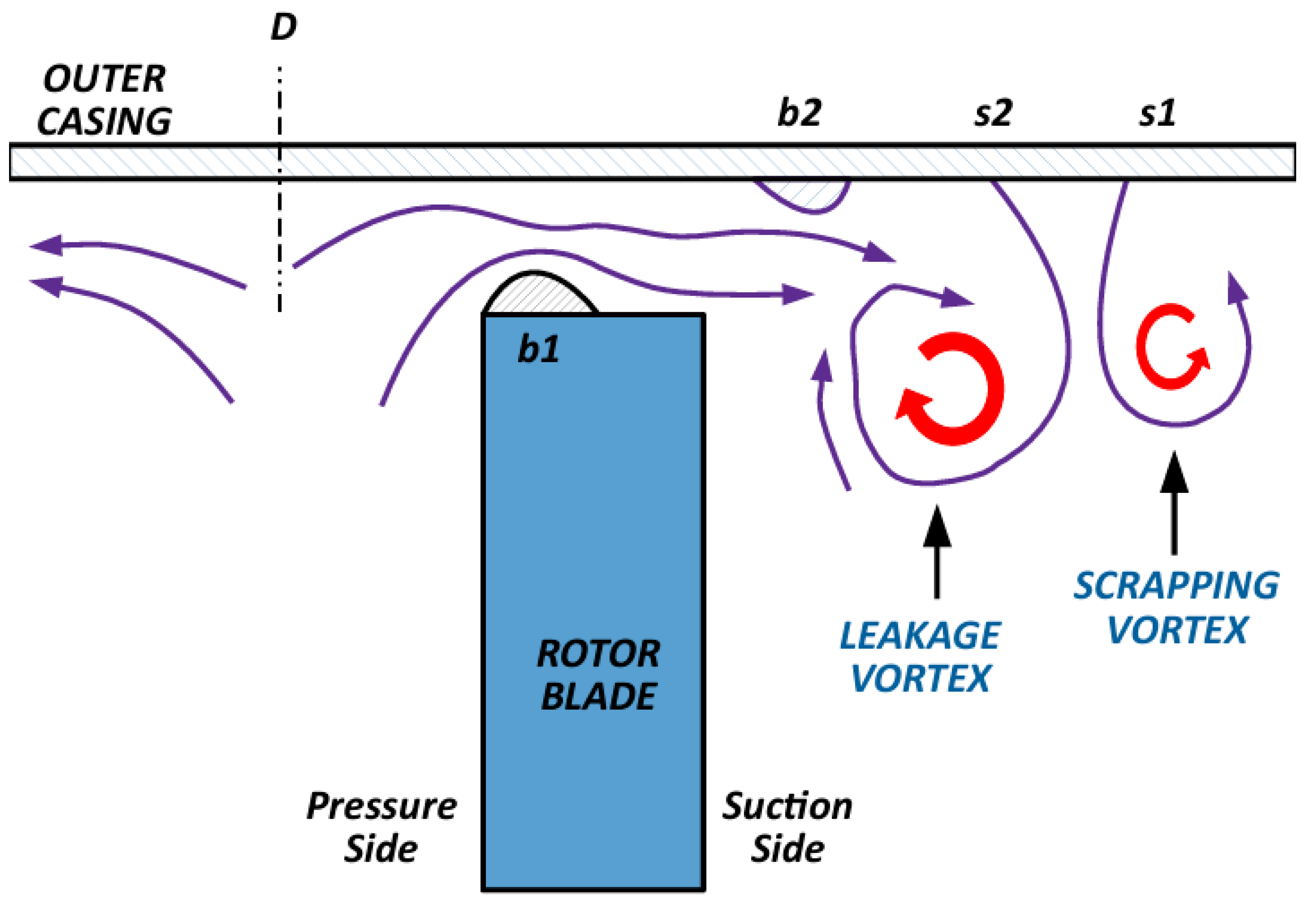
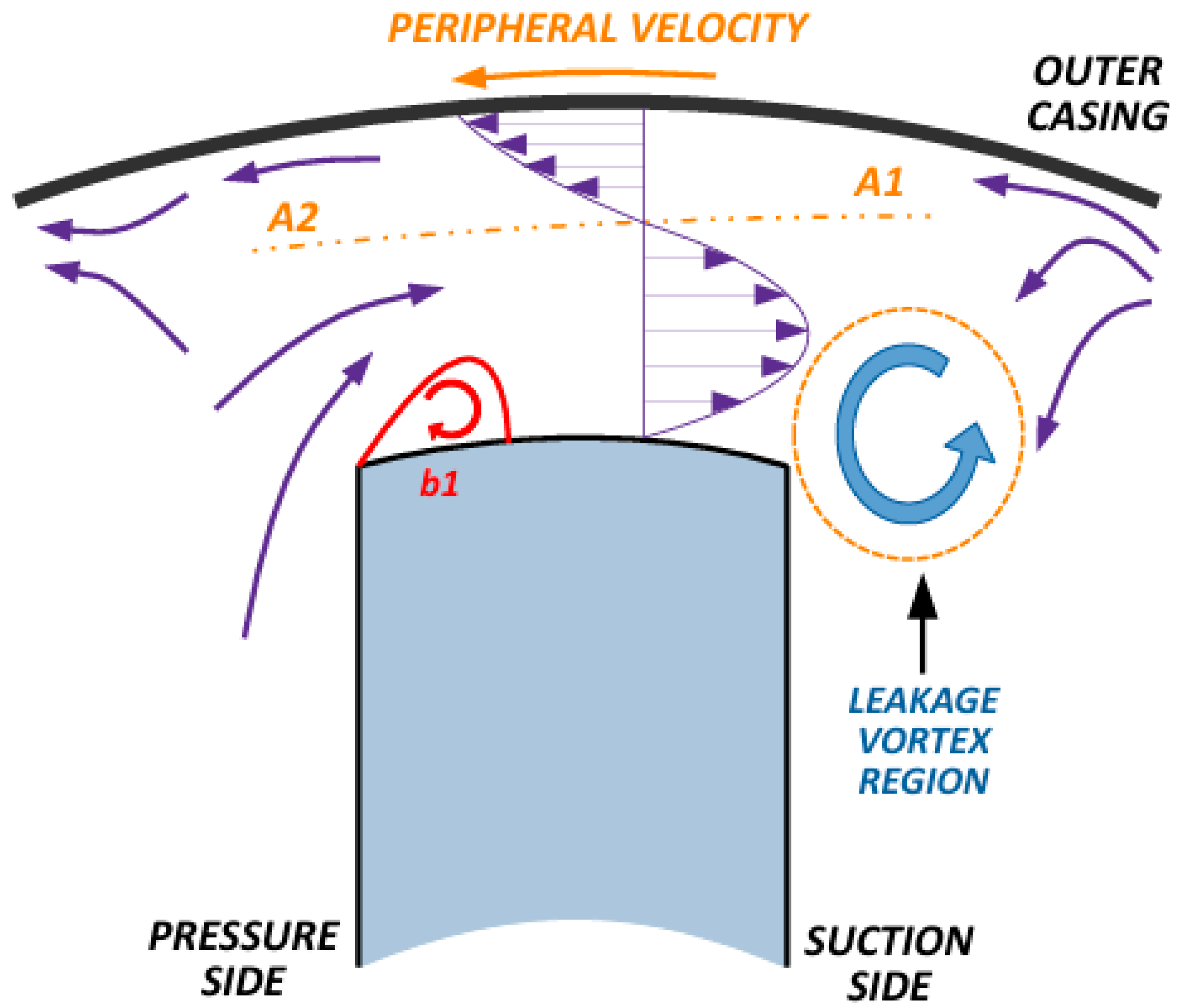
2. Tip Leakage Effects

2.1. Leakage Behavior

To obtain accurate results of the flow characteristics inside a turbomachine, turbulence must be properly quantified. The machine’s geometrical details are also very important. Hence, the tip clearance between the rotor tip and the casing is usually considered, and the gap must realistically represent the actual component.
Due to the complex geometry and pathway of the fluid motion through a turbomachine and, in this case, the existence of fixed and rotating blade rows, the flow characteristics and secondary losses generate the increase in energy losses and, consequently, entropy [27,28]. Each of these energy loss sources has motivated the development of several physical–mathematical models based on test data in order to quantify them, as can be seen in references [29,30,31,32].
Specifically analyzing the flow at the rotor tip region, this has a great impact on axial turbomachines, which has motivated different studies over the years [33] related to the impact on their performance and also regarding the heat transfer at the blade tip region [34,35,36]. In this work, following the same approach of previous research [16,18], only the tip leakage effects on the turbine stage efficiency and performance are discussed.
A representation of the leakage flow in the tip region is shown in Figure 1. In this illustration, region D represents the streamline location on the endwall. In this region, the leakage flow is divided into bubbles b1 and b2 to exemplify the flow attachment at the blade tip surface in the gap region, involving the machine casing. Usually, bubble b1 is formed at the blade tip corner, and bubble b2 is located near the blade’s suction side. A detailed discussion of this flow behavior is presented by Dey and Camci [37].
Other than bubbles b1 and b2, Figure 1 also illustrates the location of regions s1 and s2 that are, respectively, related to the scrapping and leakage vortexes. The first one is generated on the main flow, while the second is formed by the fluid that crosses the tip region. The leakage flow that generates the leakage vortex meets with the scrapping vortex, and the result of the interaction will increase or decrease the losses in that region, depending on the rotation direction of those vortexes; if these vortexes have the same direction, losses are increased; otherwise, they decrease [33].
The present work focuses on the hydraulic turbine for aerospace applications. However, hydraulic turbines are also designed for electrical generation and are a source of renewable energy. These machines operate based on pressure energy differences, as presented in reference [38]. The desensitization technique evaluated in the current research can be extended to other hydraulic turbine applications aiming at efficiency improvement.
Due to the relative movement between the turbine casing and the rotor blades and also considering the no-slip flow condition at the walls, the velocity field profile in this region becomes relatively complex. A representation of this velocity profile is shown in Figure 2. Due to the flow characteristics in this region, as illustrated in the figure and discussed in previous research [18,23,37], a stagnation point appears in the velocity profile where the flow direction changes. This behavior is repeated in each longitudinal section along the blade thickness, generating a stagnation line at the tip, represented in Figure 2 as the A1–A2 line [37]. Furthermore, bubble b1 alters the flow characteristics and may facilitate fluid leakage from the pressure side to the suction side, leading to an increase in the discharge coefficient in that region and higher aerodynamic losses [37].
In summary, all the effects described in this section impact the performance of axial turbines and must be considered during the detailed design of these machines. The importance of these effects can be seen in the number of academic works developed over the years addressing these issues [3,16,18,37,38,39,40,41,42].

2.2. Cavitation

Cavitation is a phenomenon that harms hydraulic turbomachines and shortens their lifespan. It occurs when a drop in static pressure causes part of the flowing fluid to vaporize [43]. In the specific case of turbopumps used in rocket engines, these components operate under high pressure rates and rotational speeds, which favor the occurrence of the phenomenon [44]. For this reason, cavitation emergence is practically inevitable, and there must be a compromise between the existence of the phenomenon and the component design parameters [45].
Cavitation is a transient process [46] and also a multiphase phenomenon. Despite these characteristics, it was already demonstrated in previous works [16,17] that steady-state monophase numerical CFD analyses can be used to carry out simulations of this phenomenon for hydraulic turbomachines. The same approach proposed in [16,17], and replicated in the results presented in [18] is applied in this research, and the phenomenon is considered to occur in the locations where the flow static pressure is equal to the water vapor pressure.
It is worth mentioning that the numerical analyses of this phenomenon are not limited to turbomachines, and this has already been evaluated in different works [47,48,49,50,51,52]. However, there is a lack of research evaluating the cavitation on a turbopump, which justifies the development of more studies on this area; numerical studies found in the open literature usually evaluate this phenomenon for other turbomachines [53,54,55,56,57].

3. SSME LOX Booster Turbopump

The SSME was the propulsion system designed to be installed in one of the most successful aerospace projects, the space shuttle [58]. This LPRE operates with LOX and LH2; these propellants were selected due to the fact that this was the combination that provided the highest specific thrust at that time [33]. A diagram with the thermodynamic cycle of this engine is presented in Figure 3 [59]. A detailed discussion of this engine cycle can be found in previous works [60].
Since this research is a sequence of previous ones [18,23], the turbomachine under analysis is the same already evaluated in those works, which is the SSME oxidizer booster turbopump. This turbopump is highlighted in the schematic presented in Figure 3. As can be seen in the figure, in order to make this TP compact, the turbine is mounted inside the pump, adding complexity to its design.
In this work, following the same approach of the previous ones [18,23], only the first stage of the SSME’s LPOTP is analyzed. Its flat tip rotor geometry was obtained through some design parameters and with the support and use of AXIAL® v. 8.7.15.0 and AxCent® v. 8.7.24.0 software, developed by Concept NREC, as already described in other research [16,17].
The workflow presented in Figure 4 represents the methodology adopted in the present research work.

4. Desensitization Methods

4.1. General Considerations

Desensitization techniques involve geometric alterations to the axial turbine rotor blade tip and modify the fluid flow characteristics in this area to reduce the leakage that passes through the clearance between the blades and the machine casing. By decreasing this unwanted flow, the turbine’s efficiency and/or performance are improved, while also altering the heat transfer coefficient in the region.
However, there is no general rule that applies to all axial turbines. Each machine has its particularities and needs, depending on the geometrical and flow characteristics. They are usually classified into three different groups: squealer, winglet, and squealer–winglet. An illustration of each of these geometrical modifications is shown in Figure 5.
The benefits that can be achieved with the desensitization methods motivated the evaluation of these techniques on different turbomachines; however, the majority of them were developed for turbines that operate with compressible flow [61,62,63,64,65,66]. This historical aspect represents a great opportunity for research related to hydraulic turbomachines. However, it is also a challenge, as these analyses usually require input from previous studies. Due to the lack of available data, the geometric parameters presented by da Silva et al. [3] were used as the starting point for this research.
In this work, the analysis presented applies the winglet technique to the first stage of the SSME LPOTP. A parametric analysis varying the thickness and width of this geometric modification is carried out, and the results obtained are compared with those presented in previous publications [18,23].

4.2. Winglet

The winglet geometric modification (which can also be found in the literature as partial shroud) is characterized by being an aerodynamic component that is positioned on the rotor blade’s tip, which protrudes out of the suction, pressure, or even both sides of the blade [3]. As with any other tip desensitization, the winglets are used to prevent the leakage at the gap region, increasing the turbomachine performance; in addition, one of the aims of this technique’s application is to decrease the drag and the tip vortex.
The behavior of the flow over a pressure-side winglet tip is illustrated in Figure 6 [37]. As already mentioned in this document, in the internal flow of an axial turbine, a leakage vortex is formed near the rotor blade’s suction side. This behavior can also be seen in Figure 6. However, the pressure-side geometric extension created by the winglet can significantly affect the flow behavior in this region, weakening the leakage vortex [3].
Winglet geometries are usually defined by two parameters, which are the element thickness and width [67]. Figure 7 shows an illustration of these parameters. These are the geometric dimensions that are varied and sometimes optimized in order to analyze the effect of their modifications on the turbine stage analyzed in this research.
The technique used to enhance or modify the winglet geometry has been extensively studied over the years. Dey, Camci, and Kavurmacioglu [68] evaluated the effects of different winglet geometries in their research. The results show that the configuration with the modification at the blade tip on the pressure side could provide a reduction in tip vortex momentum, also changing the flow conditions on the gap and reducing the leakage.
A numerical and experimental analysis to investigate the benefits of applying a pressure-side winglet installation was presented by Zhou et al. [69]. The results obtained were compared with those of the original axial turbine rotor blade, considering the common flat tip and squealer geometries. Regarding the winglet and the squealer, it was shown that the vortices generated by these geometries acted as a restriction, preventing leakage in the region. The winglet installation on the blade’s pressure side also allowed a reduction in the pressure difference at the blade tip region, in the areas close to the leading edge. However, at the blade mid-chord and trailing edge locations, this difference increased. In conclusion, the authors determined that the pressure-side winglet provides an improvement in aerodynamic performance compared to the other geometries.
In previous research, Tonon et al. [67] presented a comparison between two different winglet geometries, analyzing their effects on the performance of the first stage of the axial turbine used in the SSME LOX booster TP. Both geometries analyzed were generated with the same thickness and width values but were differentiated by their configuration at the trailing edge. One of the geometries connects to the trailing edge at an angle close to 90°, while the second one has a smooth connection. The authors concluded that the application of the winglet geometry with the smoother connection at the trailing edge provides only small performance benefits to the stage. The other geometry would be able to achieve greater improvements in this parameter. However, due to its geometrical characteristics, a larger wake region is generated at the trailing edge, increasing flow instability.
Although many studies evaluating the benefits of winglet geometries have been carried out considering the application of this technique on the blade’s pressure side, others have considered the insertion of this modification on the suction side, as demonstrated in the work by Seo and Lee [70]. The authors studied two suction-side winglet geometries, one of which allows variation in the width dimension (VWSS) and the other with fixed dimensions (CWSS). The results presented show that both strategies are able to reduce aerodynamic losses when compared with the flat tip.
In addition to the research presented in this section, there are many other studies that can be found in the open literature evaluating the benefits of pressure, suction, or even both sides’ winglet geometries [71,72,73,74,75,76,77,78,79]. For reference, only pressure-side winglet geometries are analyzed in this work.

5. Computational Fluid Dynamics Considerations

Following the same approach as in previous research [18], the geometry evaluation process presented in this work was initiated with reference to the parameters of the winglet geometry proposed by da Silva [3], considering 2.70% for width and 2.90% for thickness. Both percentages are relative to the rotor blade height. To carry out the parametric analysis proposed, widths of 5.40% and 8.10% and thicknesses of 5.80% and 8.70% were also used. The combination of these dimensions generates nine different winglet geometries to be analyzed. For example, the combination of the 2.70% width with each one of the thickness values established (2.90%, 5.80%, and 8.70%), generates three geometries. The same reasoning is applied to the other width values (5.40% and 8.10%). These geometrical proportions have been selected based on best practices applied in axial turbines used in gas turbines [3]. Furthermore, the rotor blade height studied in the present work is very small, and smaller proportions would not provide sufficient geometric changes to result in a significant improvement in turbomachine performance. This is why some geometrical proportions were increased.

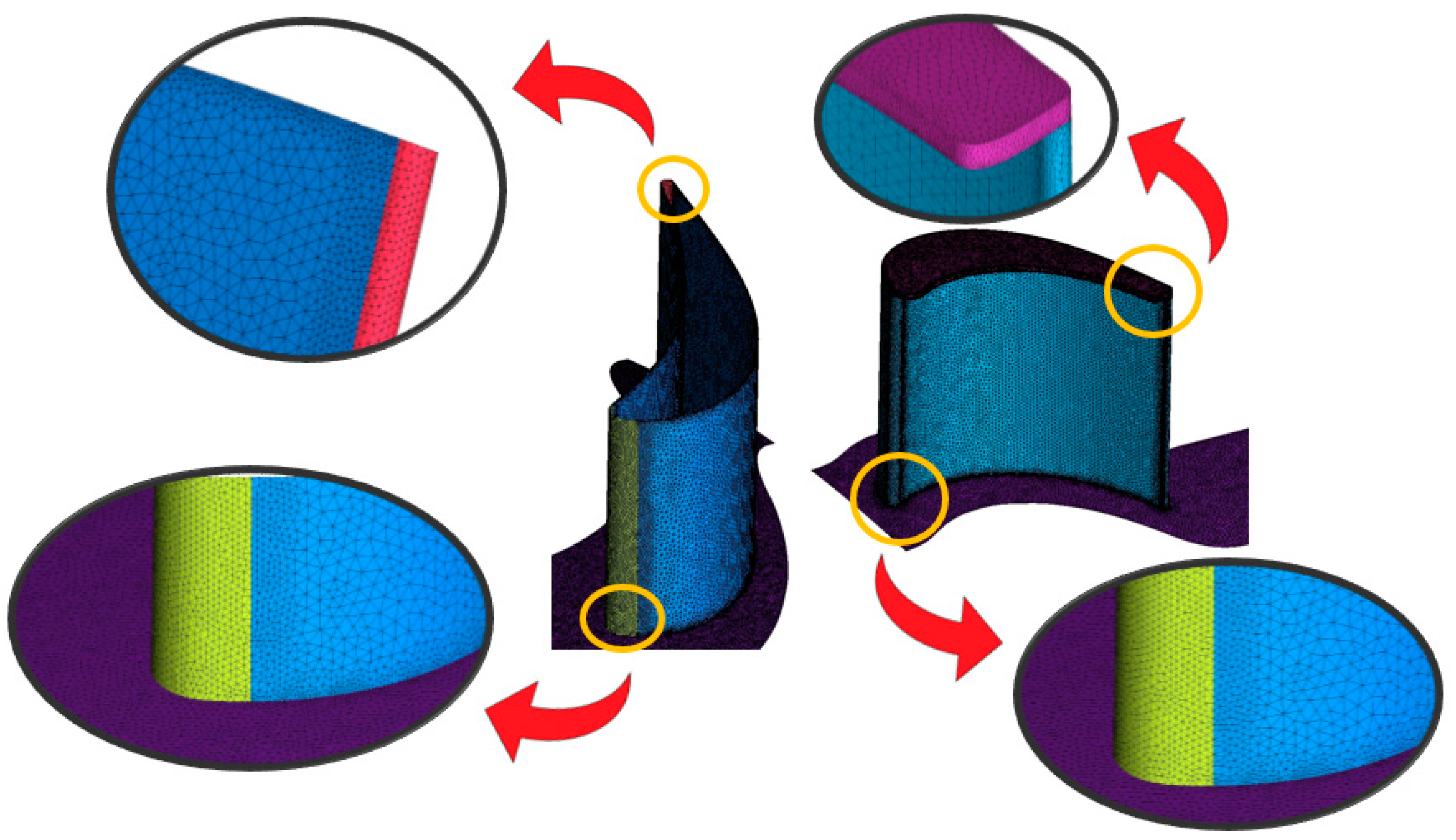
5.1. Mesh Characteristics

ICEM v. 19.2 commercial software was used to perform the mesh generation and geometrical modifications on the rotor tip geometry, following reference [18]. Tetrahedral unstructured meshes were generated following their best practices to obtain adequate control volume shapes, in order to properly represent the details of the geometries analyzed. An illustration of these meshes is shown in Figure 8.
A total of 25 prism layers were generated at the walls to determine the boundary-layer region with good resolution and accuracy. Although this number of layers significantly increases the elements’ number and, consequently, the computational cost, this is necessary to avoid the use of wall functions coupled with the turbulence model. In this work, the turbulence equations were integrated until reaching the walls. More discussion about this subject will be discussed in further sections.

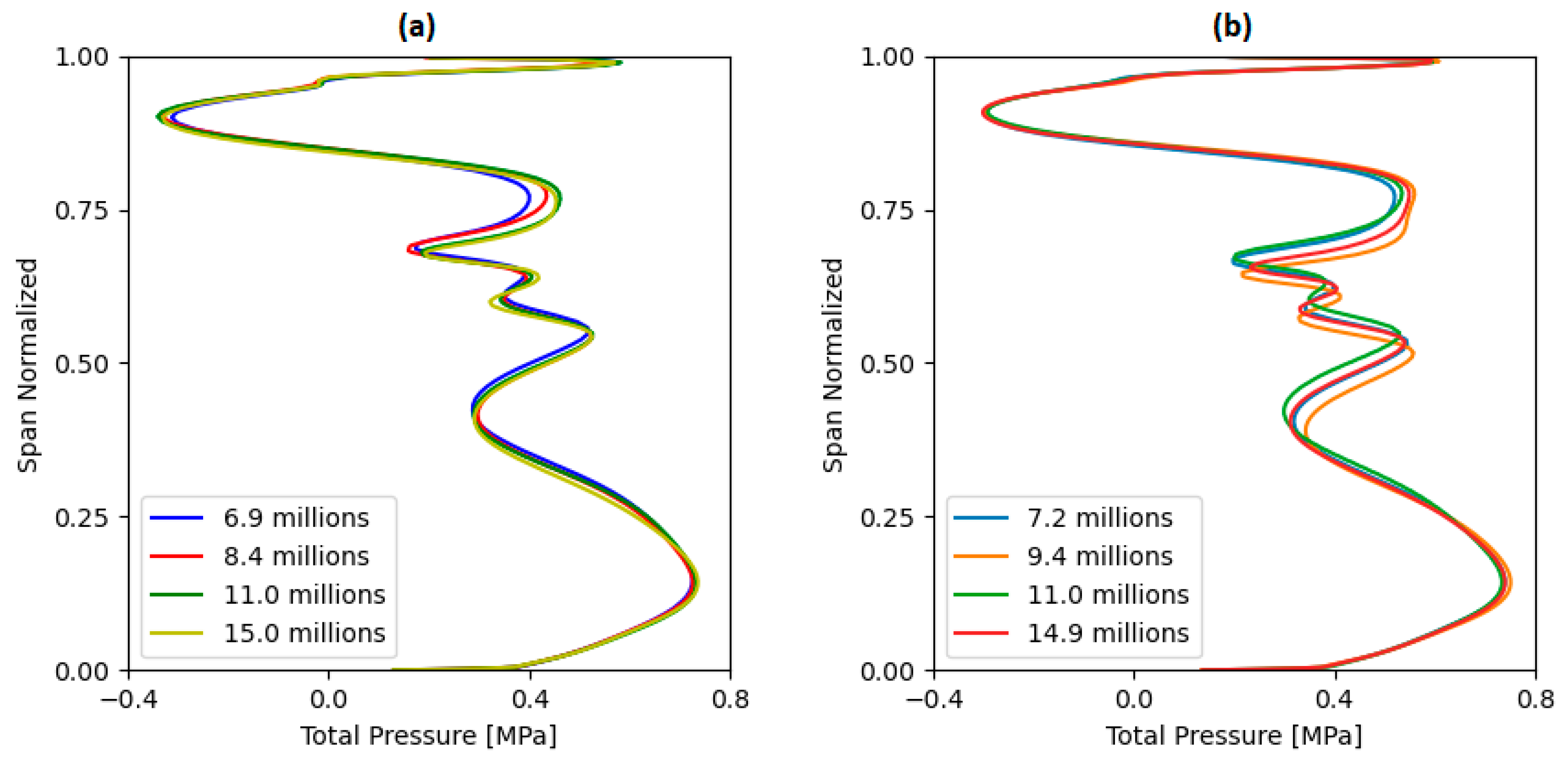
5.2. Independence Analysis

The mesh independence study carried out in this work follows the same procedure described in [18]. Four progressively refined computational meshes were generated, and with their independence guaranteed, one of them was chosen to be used in the analyses. The number of elements in each of these meshes is shown in Table 1.
The trailing edge total pressure distribution from hub to tip was compared for each mesh configuration. Figure 9 presents this comparison for two of the winglet geometries examined. As shown, there is minimal variation in the distribution of this parameter, indicating that the mesh independence condition has been met. Mesh 3 was selected to carry out the simulations for all the geometries analyzed in this work since mesh independence had already been achieved and this mesh has an intermediate number of elements, which is advantageous for saving CPU time and memory storage during the computations.

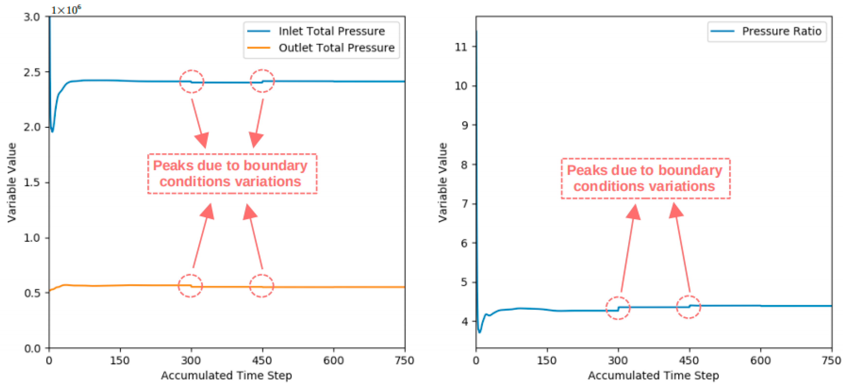
5.3. Initial and Boundary Conditions

An adequate initial condition is important to avoid numerical instabilities during the first numerical iteration, even numerical divergences [3]. These conditions initiate the numerical solution of the systems of partial differential equations (PDEs), for spatial integration, and ordinary differential equations (ODE), for time integration.
Boundary conditions are set for each numerical domain surface. Depending on the turbomachine’s operational characteristics, these conditions will be different. In the present paper, the following boundary conditions are set at the surfaces:
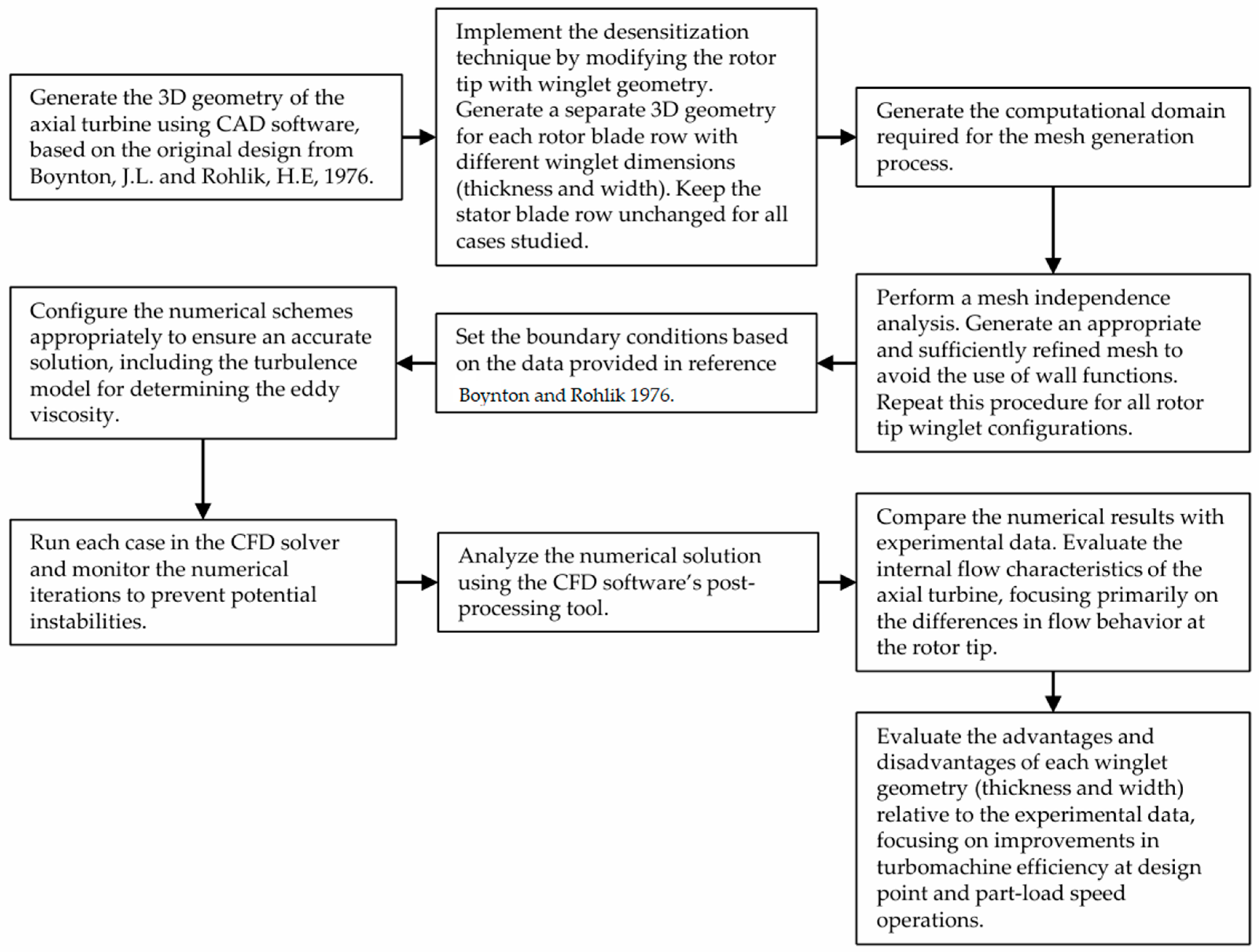
  • Stage inlet: entry velocity vector, total temperature (294 K), mass flow, and intensity of turbulence (5%);
  • Stage outlet: average blade hub static pressure, which varies until reaching the casing, using the radial equilibrium equation;
  • Stator–rotor interface: mixing-plane;
  • Wall surfaces: non-slip condition;
  • Blade-to-blade surfaces: periodicity.
In the experimental analyses developed and reported by NASA [26], the total pressures at the stage inlet and outlet were kept constant over its entire operational range. These pressures are, respectively, 2,410,000 Pa and 550,000 Pa. Different rotational speeds were considered and analyzed based on this information. At the machine outlet, the static pressure and mass flow values were varied while keeping the inlet and outlet total pressures within ±0.1% of the values reported in [26]. This same approach was already applied in previous research [18,23].
Additionally, although the analyzed turbine operates with LOX, the tests reported by NASA [26] were carried out using water as the working fluid. This was also the fluid used in the numerical simulations.

5.4. Numerical Scheme

The numerical schemes applied in this work to calculate the general fluid mechanics equations numerically are described in previous work [16,18]. The commercial software ANSYS CFX v. 19.2 was used to solve the Reynolds-averaged Navier–Stokes (RANS) equations. First- and second-order discretization schemes were applied in the convection terms of the turbulence model and momentum equations. A modified Rhie–Chow discretization method [80] was applied in the numerical scheme to solve the RANS equations. The time marching scheme is implicit. For the flow eddy viscosity determination, a two-equations k-ω SST model was employed.
Specifically, regarding the SST two-equation model, in order to avoid the use of wall functions, the computational mesh must be generated to keep the values of y+ below 2. Still, for this model, when the y+ value is between 2 and 11, a blend of low Reynolds formulation and wall functions is set by default. If the y+ parameter is between 11 and 300, only wall functions are used [81]. The y+ values of all the meshes used in this research were kept below 2.

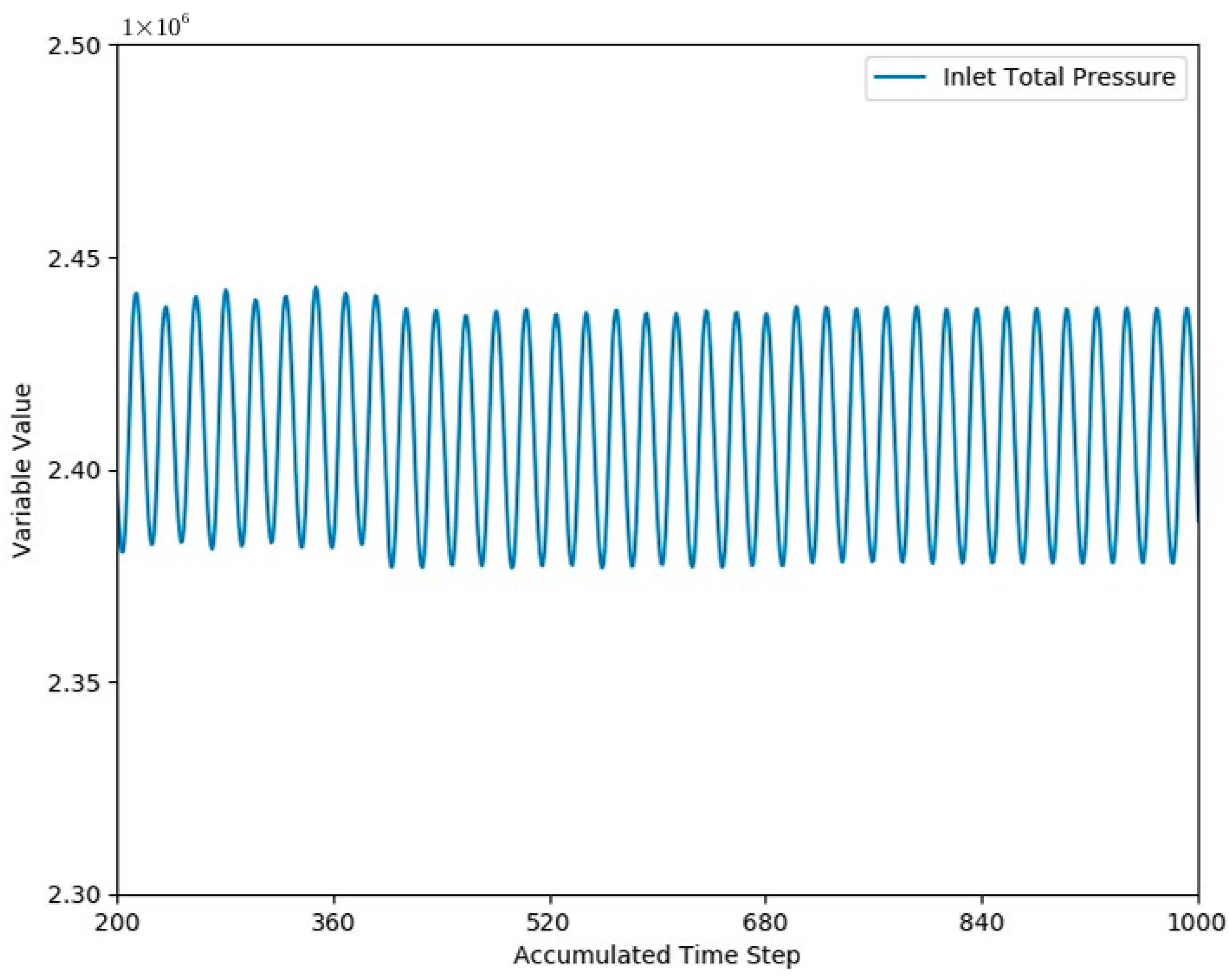
5.5. Residual Evolution

Regarding the CFD simulations, the numerical residuals’ order along the iterations must be reduced in order to achieve the results’ convergence [18,23]. The momentum, energy, and continuity equations’ residuals history are shown in Figure 10; the peaks noted in these residuals are the result of variations in the boundary conditions. These simulations were run on a Supermicro computer, provided Scherm Brazil Company, São Paulo, Brazil, equipped with a 48-Cores/4 Nodes Intel® Xeon® Processor E5-2620 v3 (2.40 GHz) with 128 GB of RAM.
Other parameters employed to track numerical convergence included conservative variables, pressure ratio, and inlet and outlet total pressure. The behavior of these variables is illustrated in Figure 11. During the process of obtaining the numerical solutions, the monitored properties oscillated around an average value for certain rotational speeds. This issue was faced during the 2113, 2454, and 2795 rotational speeds; it is a characteristic already observed in previous research [16,18] and is linked to the transient nature of the flow under these operating conditions. Figure 12 illustrates this behavior. In these cases, a representative value of the properties was obtained by the average of the last 200 iterations.
Furthermore, especially at low rotational speeds and for some of the studied geometries, it was impossible to obtain an approximate solution. This behavior arises because, depending on the geometry, the flow characteristics become more complex due to the different vortex formations. This flow field behavior can cause numerical instabilities during the iterations. Under these conditions, instability and divergence problems occurred. For these reasons, each analyzed geometry has a different number of operational point results.

6. Results

6.1. Stage Efficiency

The results obtained with the application of the winglet geometries at the rotor blade tips were compared with those of the flat tip and squealer geometries available in [18,23]. The results of the nine geometries analyzed are divided into different graphs. Figure 13a shows the total efficiency versus the blade–jet velocity results for the 2.90% winglet thickness geometries, combined with various width values. Figure 13b and 13c display the same analysis for 5.80% and 8.70% thicknesses, respectively. To aid in quantitative comparison, the results for these winglet geometries were interpolated using a third-degree polynomial function. The following equations were employed to calculate the parameters presented in these figures.
η T T = 2 π N τ p T , i p T , o m ˙ ρ
U C 0 = 2 π N R 2 p T , i p T , o ρ
In the results presented in Figure 13a–c, it is noted that the winglet width has almost no impact on the turbine efficiency. For winglet geometries with a thickness of 2.90%, the average efficiency increases over the stage operational range were 0.16%, 0.18%, and 0.24%, respectively, for the 2.10%, 5.40%, and 8.10% widths. Considering the winglet geometries with 8.70% thickness, these average increases were 2.22%, 2.23%, and 2.08%. For these two thickness values, it is shown that the winglet width has little influence on the state total efficiency.
However, for Figure 13b, slightly different behavior was observed. In this figure, there is a significant difference between the results obtained for the 2.70% width compared to those obtained for the others. Additionally, the number of operational conditions that were possible to simulate with 5.40% and 8.10% widths was fewer than for the 2.70% width, which indicates that this parameter increases flow instabilities for a transient condition and also increases numerical instability. The boundary conditions used in the present work consider a steady-state regime; hence, a transient flow condition can push the numerical iterations towards divergence.
Despite these results, it is noted that only widths above 2.70% impacted the stage efficiency. For all the other geometries studied, no significant influence was noted from this parameter change. For this reason, another analysis was conducted comparing different winglet thicknesses while keeping the width constant. Figure 13d shows this analysis; the effects of the variation in winglet thickness are observed, with the width kept at 5.40%. As shown in this figure, an increase in winglet thickness tends to improve the turbine’s total efficiency. This efficiency increase is much more significant for thickness variations from 2.90% to 5.80%. The average increase in total efficiency across the operational range, compared to the flat tip, is 0.18%, 2.03%, and 2.23% for the 2.90%, 5.80%, and 8.70% thicknesses, respectively.
Comparing these results with the ones presented in previous research [18], it is concluded that the winglet application is able to provide better improvements on the analyzed turbine performance than the squealer technique. For reference, the highest average efficiency increase, in comparison with the flat tip, obtained with the squealer geometries was 1.43%. As mentioned above, for some winglet geometries, this average increase is higher than 2.0%.
In summary, the stage total efficiency tends to increase with the increase in the winglet thickness. However, it is noted that there must be a maximum value of this parameter from which the efficiency remains constant.
The polynomial coefficients displayed in Figure 13 are provided in Table 2. The quantitative comparisons between the flat tip and the winglet geometries are presented in Table 3, Table 4 and Table 5 for the 2.90%, 5.80%, and 8.70% thicknesses, respectively. The average efficiency increase for each of these geometries is also listed, which is the arithmetic average for all the operational conditions.

6.2. Effect of Squealer Geometries in the Axial Turbine Flowfield Characteristics

Figure 14 and Figure 15 show the streamlines and static entropy contour regions in the tip clearance region, respectively. Specifically, for Figure 14a and Figure 15a, these results are related to the rotor blade flat tip geometry, which was already presented in previous works [18]. The flow characteristics of the blade’s suction side are joined by the leakage flow, and the formation of a leakage vortex is observed. It is also observed that the flow on the suction side detaches from the blade surface. These secondary flows contribute to the development of the trailing edge wake region.
Figure 14 and Figure 15 also show the streamlines and static entropy contours for the 2.90%, 5.80%, and 8.70% winglet thicknesses, with the element width kept at 5.40%. With the change in rotor tip geometry, the vortex characteristics in the tip region are also modified. These vortex formations interact as secondary flows in the turbine’s main flow, generating different entropy zones and creating wakes. Comparing the behavior of the streamlines of the winglet geometries with those of the flat tip, similar behavior is observed. However, there are differences in the flow at the trailing edge region. The first difference concerns the leakage vortex, which, with the winglet application, shows a higher velocity. This higher velocity may indicate that the leaked fluid has greater momentum compared to the common flat tip. Furthermore, there is an increase in the stagnation region at the trailing edge location. This can generate flow disturbances that tend to increase the stage losses and may be associated with the trailing edge geometry. Regarding the static entropy contours, it is noted that the winglet results show lower intensity of this property compared to the flat tip. These are expected results, as the efficiency of the winglet geometries is higher than that of the flat tip.
In order to have a better understanding of the association of these vortices, Figure 16 was generated based on a stationary reference frame view. For the flat-tip rotor configuration, this association is shown in Figure 16a. By analyzing this figure, it is possible to observe that the leakage and scraping vortices have different rotation directions, which reduces the region losses.
Figure 16b, 16c, and 16d show these vortices for the winglets with 2.90%, 5.80%, and 8.70% thickness and 5.40% width, respectively. The results in Figure 16b are very similar to those shown in Figure 16a, which is expected, since the average efficiency over the operational range obtained with the winglet of 2.90% thickness and 5.40% width is very close to that of the flat tip. In Figure 16c,d, it is possible to visualize that the vortex behavior at the blade tip, midspan, and hub locations has been significantly altered. The scraping vortex is displaced in relation to the flat-tip case due to the effects of the leakage and passage vortices. This is different behavior compared to the results presented in previous works [18] related to squealer geometries; for these geometries, the scraping vortex was displaced towards the blade height. Furthermore, the leakage flow velocity through the blade tip is greater than that observed for the flat tip.
As already mentioned, cavitation is a harmful phenomenon that can cause significant reductions in turbomachine performance and erosion problems on metallic surfaces. Regarding rocket engines, the damage caused can lead to system failure. Some applications have requirements that make operation without cavitation impossible. Soft and moderate cavitation, in general, are acceptable for some applications, but their levels should be analyzed and monitored.
The last set of results generated in this study is a comparison between the cavitation regions along the turbine stage with and without the application of the desensitization techniques. These results are presented in Figure 17 and were generated using the same approach proposed in [16,17] and applied in previous research [18,23]; cavitation is considered to occur in regions where the pressure reaches the water vapor pressure (~2300 Pa).
Figure 17b, 17c, and 17d show the possible cavitation regions for the winglets of 2.90%, 5.80%, and 8.70% thicknesses and 5.40% width, respectively. Considering the results in Figure 16b, no significant differences are observed in relation to the flat tip. For the other geometries, at the blade tip location, cavitation tends to become more intense, and at the blade’s suction side, a considerable reduction in this phenomenon is observed. This is an important result, since this reduction tends to decrease the LPRE components’ damage. The cavitation characteristics in the blade tip region can be carefully evaluated during the turbomachine design phase to avoid performance issues and unsafe operational conditions.
Since the same approach described in [16,17,18,23,25,46] was utilized to generate these results, they were obtained through monophasic flow simulations. This is an approximation that can provide adequate results when compared with multiphase flow simulations, as already discussed in these previous works. Although this approach is sufficient for the scope of this research, the use of multiphase simulations is necessary for analyses that require a detailed evaluation of the phenomenon.
The results obtained in this work show that the application of the proposed treatments is able to provide interesting benefits for the axial turbine analyzed. Regarding turbine efficiency, the results of the winglet geometries show that these could increase this parameter even more than the squealer geometries analyzed in previous works [18]. It was also shown that the width dimension in the winglet configuration has almost no impact on turbine efficiency. Regarding the winglet thickness dimension, its increase tends to enhance turbomachine performance.
Comparing the results obtained from the numerical simulations considering the rotor flat-tip and winglet configurations, it is possible to observe that these geometrical arrangements also impact the cavitation issues, mainly at the suction-side region. There is a cavitation increase in the rotor blade tip region. These results are relevant, since they could affect the turbine life cycle.
Despite the possible benefits of the modified geometries’ application on the turbine stage efficiency and other flow characteristics, the analyses presented in this research are related only to the fluid flow inside the turbomachine. There are other engineering aspects related to the operation of these mechanisms that must be evaluated through structural analyses (stresses, natural frequency, vibration, Campbell and Bode diagrams), in order to validate the use of these techniques in a real turbine. Considering the winglet width and thickness geometrical dimensions, these have a crucial impact on the relationship between fluid dynamics and mechanical characteristics, as well as the cavitation regions along the stage.

7. Conclusions

The present work is a continuation of previous research [18,23] that evaluates the application of desensitization techniques in a hydraulic axial turbine. The results shown in this document are related to the application of different winglet geometries; although these techniques have been extensively evaluated on gas turbines, there is a lack of studies evaluating their benefits on turbomachines that operate with incompressible working fluids.
Performance improvements in turbomachinery through desensitization techniques are typically in the order of 10−1%. Therefore, the computational mesh used to solve the governing equations must be generated and evaluated with high precision. A critical parameter in this context is the dimensionless wall distance, y+, which must remain sufficiently low to avoid the use of wall functions and thus enable more accurate resolution of the near-wall flow. In the present study, the y+ values are maintained below 2 to ensure full integration of the turbulence model equations up to the wall, thereby eliminating the need for wall function approximations.
This research uses the first stage of the SSME LPOTP hydraulic axial turbine as a reference. Numerical simulations and computational mesh generation processes were carried out, respectively, making the use of CFX CFD solver and ICEM v.19.2 commercial software, developed by ANSYS®.
The main conclusions obtained in the present research are as follows:
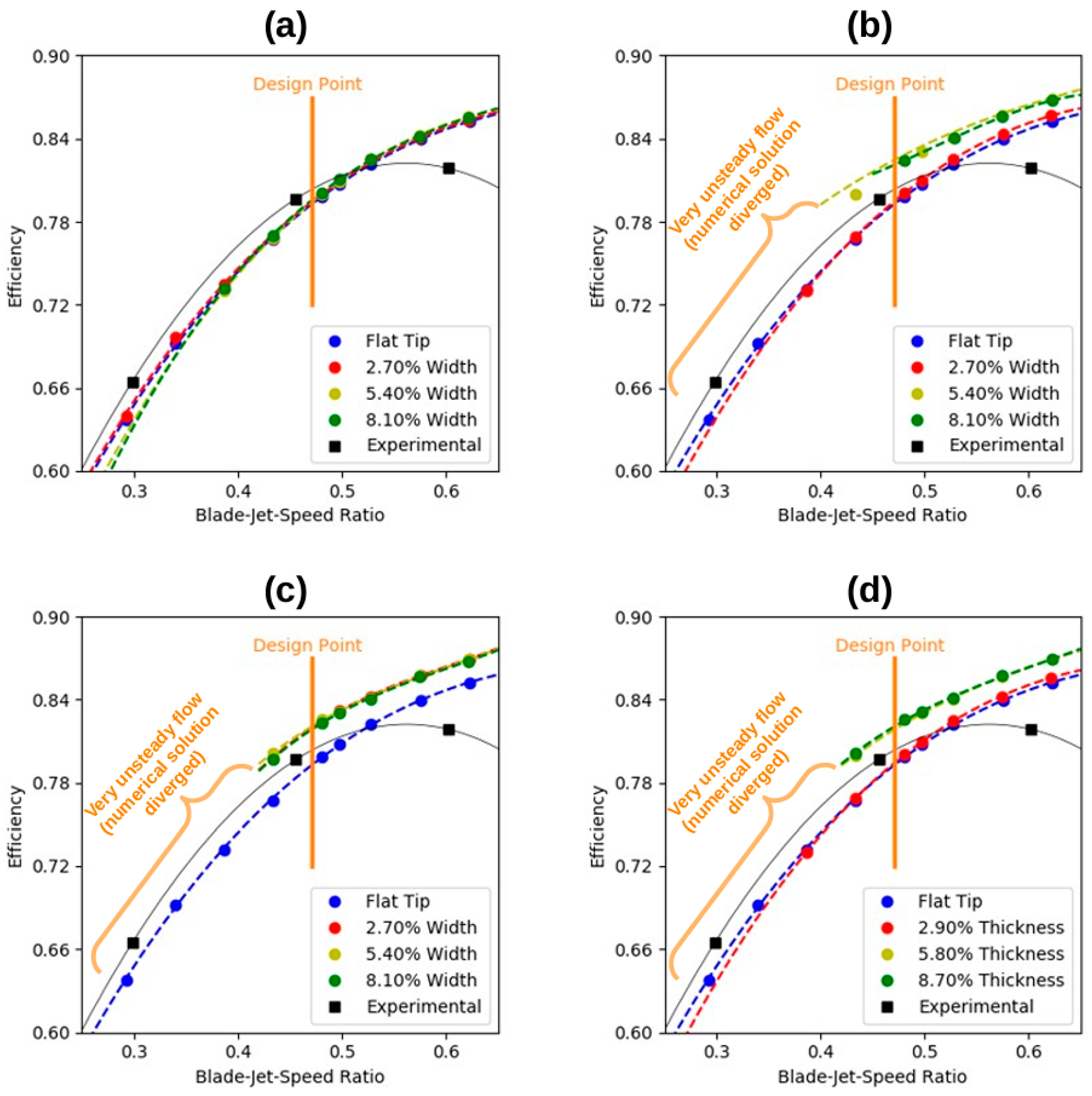
  • A winglet parametric analysis was performed considering 2.90%, 5.80%, and 8.70% thicknesses and 2.70%, 8.40%, and 8.10% widths. These percentages are all in relation to the blade height. The results of the nine proposed geometries show that increasing the winglet thickness has a positive impact on the turbine’s total efficiency—the greater the winglet thickness, the greater the stage efficiency. However, there is a maximum value for this parameter, beyond which the efficiency remains constant. The winglet geometry with 8.70% thickness and 5.40% width provides the highest stage efficiency average increase (2.00%) over the entire turbine operational range, in comparison with the rotor flat-tip configuration. For reference, the highest average increase in this parameter for the squealer geometries, available in [18], was 1.43%.
  • The winglet width dimension almost does not impact the stage efficiency.
  • In general, the results found in this work show that the winglet geometries analyzed are able to provide a greater increase in stage efficiency than the squealer geometries evaluated in previous research [18], considering both design and off-design operating conditions. In the case of the squealer, for the design point, the maximum efficiency improvement was 1.62% [18], compared to the current improvement of 2.23% using the winglet desensitization technique.
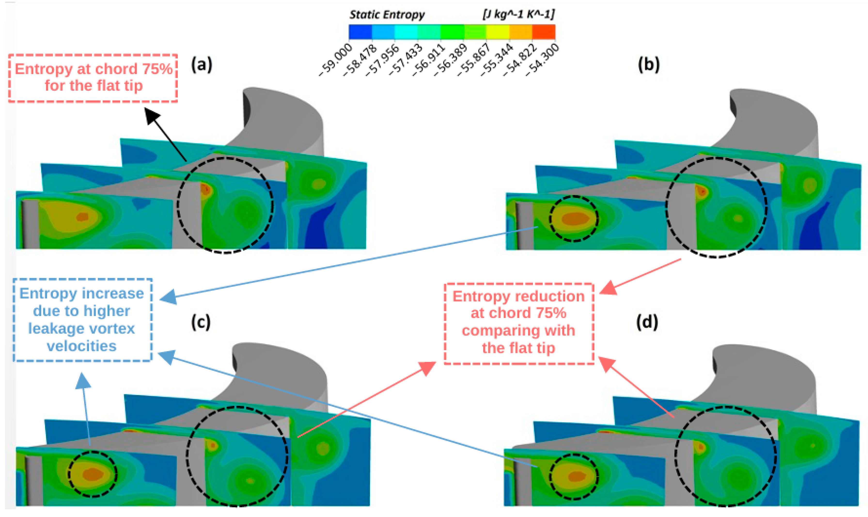
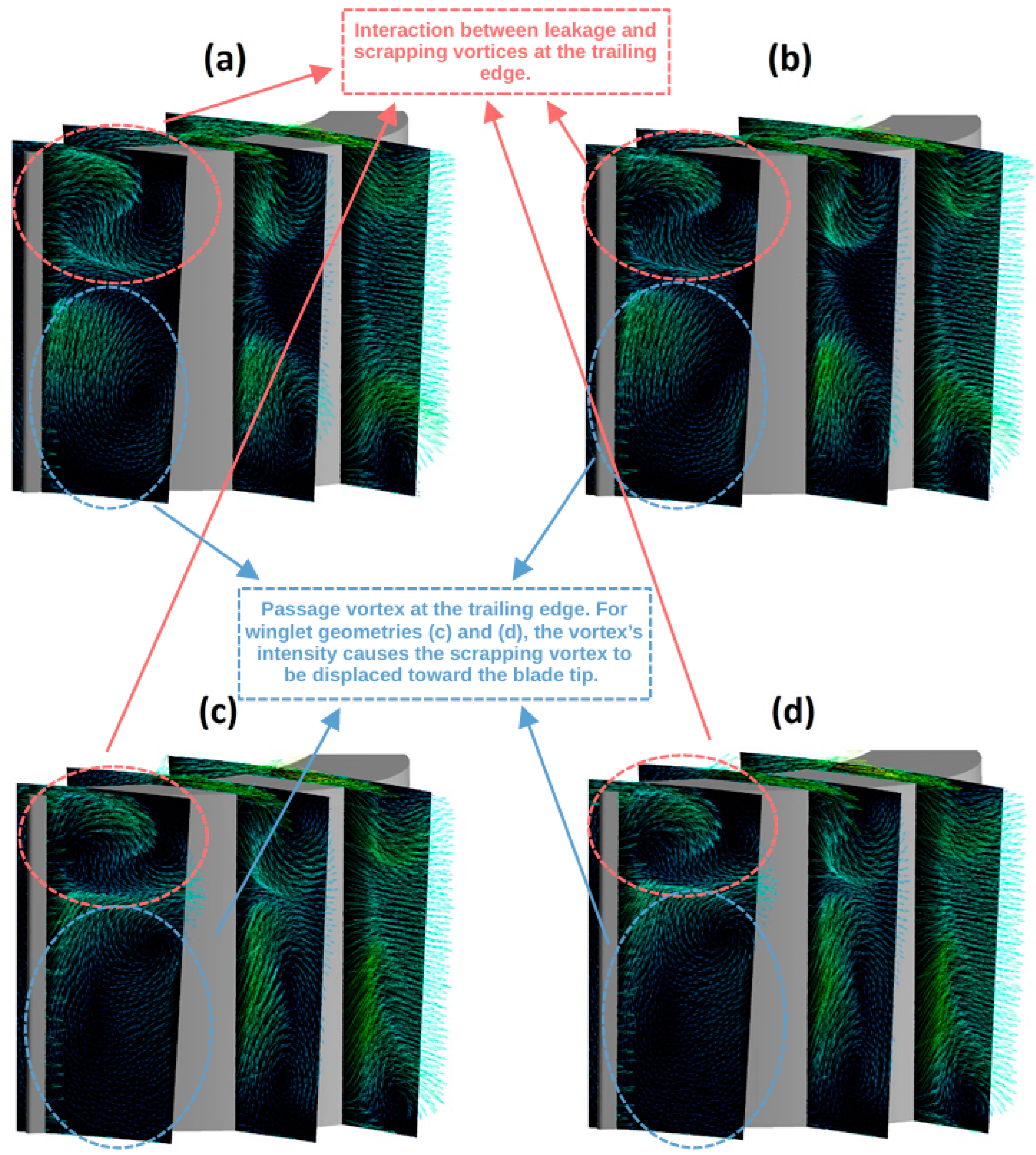
  • Regarding the vortices in the tip region, the same behavior shown in previous works for the flat tip and the squealer geometries was maintained for the winglet modifications: they have a different rotation direction, reducing the losses in the region. However, for the winglet geometries that provide the best performance results, it is noted that the scrapping vortex is displaced in relation to the flat-tip case due to the effects of the leakage and passage vortices.
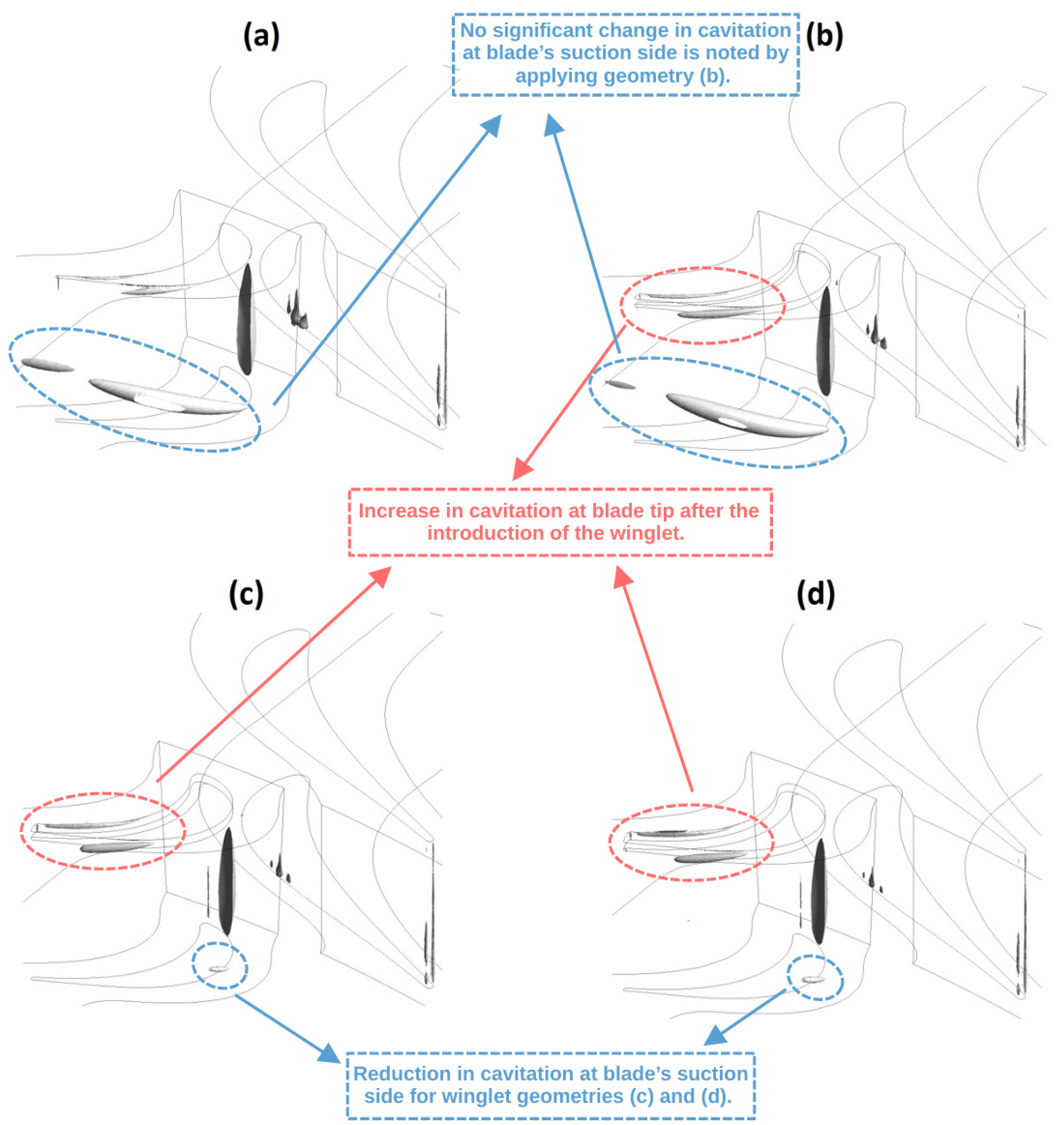
  • The cavitation results obtained with the application of winglet geometries show that it would be possible to reduce the occurrence of this phenomenon at the blade’s suction side for some configurations. However, for these same configurations, there is an increase in the cavitation at the tip region. The effects of these combined changes on the turbine life cycle must be carefully analyzed through structural simulations and tests.

8. Future Research

Drawing upon the results and conclusions presented in this study, the following recommendations for future research are proposed:
  • All the proposed and evaluated geometries in this work are blade pressure-side winglet geometries along the full blade chord; it would be interesting to also develop analyses for a partial winglet with dimensional variations distributed along the blade chord.
  • In order to validate the results obtained by the numerical simulations, the development of experimental tests will be very useful.
  • Regarding Figure 17, a more detailed study needs to be conducted based on the simulation of multiphase flows to analyze the effect of the cavitation region on the tip clearance and verify its influence on turbine operating conditions and lifecycle.
  • Modern optimization techniques, such as artificial intelligence (AI) and machine learning (ML), can be used to provide more data for turbomachinery designers to define the geometric aspects of the tip desensitization technique [82,83,84].

Author Contributions

Conceptualization, J.T.T.; Methodology, D.d.S.T. and J.T.T.; Validation, D.d.S.T. and J.T.T.; Formal analysis, D.d.S.T.; Investigation, D.d.S.T.; Writing—original draft, D.d.S.T.; Writing—review & editing, C.B., J.K. and L.V.; Supervision, J.T.T., E.C.G., C.B., L.E.N.d.A., J.K. and L.V.; Project administration, J.T.T. All authors have read and agreed to the published version of the manuscript.

Funding

This research was funded by the Conselho Nacional de Desenvolvimento Científico e Tecnológico (CNPq—Brazilian National Council for Scientific and Technological Development) grants numbers 132726/2016-5, 141288/2018-3, and 141837/2019-5. This research received no external funding to pay the APC.

Data Availability Statement

The dataset presented in this article is not publicly available due to the confidential and/or strategic nature of the information held by the institutions that funded the development of this work.

Acknowledgments

The authors would like to thank the ITA (Aeronautics Institute of Technology) Department of Turbomachines for the support and infrastructure provided during this research work, as well as the Coordenação de Aperfeiçoamento de Pessoal de Nível Superior (CAPES—Higher Education Improvement Coordination); the Fundação de Amparo à Pesquisa do Estado de São Paulo (FAPESP—São Paulo Research Foundation); the Conselho Nacional de Desenvolvimento Científico e Tecnológico (CNPq—Brazilian National Council for Scientific and Technological Development); FINEP (Financiadora de Estudos e Projetos) Captaer III, project number 01.22.0313.00; and EMBRAER FLYMOV—Engineering Research Center, grant number 2021/11258-5, Sao Paulo Research Foundation (FAPESP). Daniel da Silva Tonon thanks Avibras for the PhD program support.

Conflicts of Interest

The authors declare no conflict of interest.

Nomenclature

CFDComputational fluid dynamics
ITAAeronautics Institute of Technology
LH2Liquid hydrogen
LPOTPLow-pressure oxidizer turbopump
LOXLiquid oxygen
LPREsLiquid propellant rocket engines
NASANational Aeronautics and Space Administration
PDEPartial differential equations
RANSReynolds-averaged Navier–Stokes
SSTShear stress transport
SSMESpace shuttle main engine
TPTurbopump
NRotational frequency
Mass flow
pPressure
iInlet condition
oOutlet condition
TTotal condition
WTurbine shaft power
τTurbine torque
ηTurbine efficiency
ρDensity
UCasingPeripheral velocity
U/C0Blade–jet–speed ratio
RTurbine rotor blade tip radius

References

  1. De Oliveira Silva, G.P.; Tomita, J.T.; Bringhenti, C.; Whitacker, L.H.L.; Da Silva Tonon, D. Interactive learning platform for the preliminary design of axial turbines and its use for graduate courses. In Proceedings of the ASME Turbo Expo, Rotterdam, Netherlands, 13–17 June 2022; Volume 5. [Google Scholar]
  2. Oliveira, I.; Silva, G.P.; Tonon, D.; Bringhenti, C.; Tomita, J.T. Interactive learning platform for turbine design using reduced order methods. In Proceedings of the ASME Turbo Expo, Virtual, Online, 21–25 September 2020; Volume 6. [Google Scholar]
  3. da Silva, L.M.; Tomita, J.T.; Bringhenti, C. Numerical investigation of a HPT with Different rotor tip configurations in terms of pressure ratio and efficiency. Aerosp. Sci. Technol. 2017, 63, 33–40. [Google Scholar] [CrossRef]
  4. Silva, L.M.; Tomita, J.T.; Barbosa, J.R. A study of the influence of the tip-clearance on the tip-leakage flow using CFD techniques. In Brazilian Congress of Mechanical Engineering—COBEM, Proceedings of the 21st Brazilian Congress of Mechanical Engineering, Natal, RN, Brazil, 24–28 October 2011; Springer: Berlin/Heidelberg, Germany, 2012. [Google Scholar]
  5. Schabowski, Z.; Hodson, H.; Giacche, D.; Power, B.; Stokes, M.R. Aeromechanical optimization of a winglet-squealer tip for an axial turbine. J. Turbomach. 2014, 136, 071004. [Google Scholar] [CrossRef]
  6. Wang, T.; Xuan, Y. A novel approach for suppressing leakage flow through turbine blade tip gaps. Propuls. Power Res. 2022, 11, 431–443. [Google Scholar] [CrossRef]
  7. Kong, X.; Liu, G.; Liu, Y.; Zheng, L. Experimental testing for the influences of rotation and tip clearance on the labyrinth seal in a compressor stator well. Aerosp. Sci. Technol. 2017, 71, 556–567. [Google Scholar] [CrossRef]
  8. Gao, Y.; Liu, Y. A flow model for tip leakage flow in turbomachinery using a square duct with a longitudinal slit. Aerosp. Sci. Technol. 2019, 95, 105460. [Google Scholar] [CrossRef]
  9. Booth, T.C.; Dodge, P.R.; Hepworth, H.K. Rotor-tip leakage: Part I basic methodology. J. Eng. Power 1982, 104, 154–161. [Google Scholar] [CrossRef]
  10. Krishnababu, S.K.; Newton, P.J.; Dawes, W.N.; Lock, G.D.; Hodson, H.P.; Hannis, J.; Whitney, C. Aerothermal investigations of tip leakage flow in axial flow turbines-part i: Effect of tip geometry and tip clearance gap. J. Turbomach. 2009, 131, 1–14. [Google Scholar] [CrossRef]
  11. Bringhenti, C.; Barbosa, J.R. Effects of turbine tip clearance on gas turbine performance. In ASME Turbo Expo 2008: Power for Land, Sea, and Air, Berlin, Germany, 9–13 June 2008; ASME, Ed.; ASME: New York, NY, USA, 2009. [Google Scholar]
  12. Moustapha, H.; Zelesky, M.F.; Baines, N.C.; Japikse, D. Axial and Radial Turbines; Concepts NREC: Vermont, VT, USA, 2003. [Google Scholar]
  13. Kim, J.; Song, S.J. Visualization of rotating cavitation oscillation mechanism in a turbopump inducer. J. Fluids Eng. Trans. ASME 2019, 141, 091103. [Google Scholar] [CrossRef]
  14. Kim, D.J.; Sung, H.J.; Choi, C.H.; Kim, J.S. Cavitation instabilities of an inducer in a cryogenic pump. Acta Astronaut. 2017, 132, 19–24. [Google Scholar] [CrossRef]
  15. Li, L.; Xu, P.; Li, Q.; Zheng, R.; Xu, X.; Wu, J.; He, B.; Bao, J.; Tan, D. A coupled LBM-LES-DEM particle flow modeling for microfluidic chip and ultrasonic-based particle aggregation control method. Appl. Math. Model. 2025, 143, 116025. [Google Scholar] [CrossRef]
  16. Lindquist Whitacker, L.H.; Tomita, J.T.; Bringhenti, C. An evaluation of the tip clearance effects on turbine efficiency for space propulsion applications considering liquid rocket engine using turbopumps. Aerosp. Sci. Technol. 2017, 70, 55–65. [Google Scholar] [CrossRef]
  17. Whitacker, L.H.L.; Tomita, J.T.; Bringhenti, C. Turbopump Booster Turbine Performance: Comparison Between Monophase and Multiphase Flows Using CFD; ASME, Ed.; ASME Turbo Expo: Oslo, The Netherlands, 2018; pp. 1–9. [Google Scholar]
  18. Tonon, D.d.S.; Tomita, J.T.; Garcia, E.C.; Bringhenti, C.; Almeida, L.E.N. A parametric study of squealer tip geometries applied in a hydraulic axial turbine used in a rocket engine turbopump. Aerosp. Sci. Technol. 2022, 122, 107426. [Google Scholar] [CrossRef]
  19. Saha, A.K.; Acharya, S.; Bunker, R.; Prakash, C. Blade tip leakage flow and heat transfer with pressure-side winglet. Int. J. Rotating Mach. 2006, 2006, 017079. [Google Scholar] [CrossRef]
  20. Zamiri, A.; Choi, M.; Chung, J.T. Effect of blade squealer tips on aerodynamic performance and stall margin in a transonic centrifugal compressor with vaned diffuser. Aerosp. Sci. Technol. 2022, 123, 107504. [Google Scholar] [CrossRef]
  21. Chen, Y.; Cai, L.; Jiang, D.; Li, Y.; Du, Z.; Wang, S. Experimental and numerical investigations for turbine aerodynamic performance with different pressure side squealers and incidence angles. Aerosp. Sci. Technol. 2023, 136, 108234. [Google Scholar] [CrossRef]
  22. He, X.; Zou, Z.; Yao, L.; Fu, C. Refined Flow Organization in Squealer Tip Gap and Its Impact on Turbine Aerodynamic Performance. Aerosp. Sci. Technol. 2023, 138, 108331. [Google Scholar] [CrossRef]
  23. Tonon, D.D.S.; Tomita, J.T.; Garcia, E.C.; Bringhenti, C.; Díaz, R.B.; Whitacker, L.H.L. Comparative Study Between Structured and Unstructured Meshes Applied in Turbopump’s Hydraulic Turbine. In ASME Turbo Expo 2020: Turbomachinery Technical Conference and Exposition, Virtual, 21–25 September 2020; ASME, Ed.; ASME: New York, NY, USA, 2020; pp. 1–13. [Google Scholar]
  24. Tonon, D.d.S.; Tomita, J.T.; Garcia, E.C.; Bringhenti, C.; Almeida, L.E.N. Effects of a Squealer-Winglet Geometry on the Aerodynamic Performance of a Hydraulic Axial Turbine Used in Turbopumps. In Proceedings of the 25th International Symposium on Air Breathing Engines (ISABE 2022), Ottawa, ON, Canada, 25–30 September 2022. [Google Scholar]
  25. Barbosa, D.F.C.; Tonon, D.D.S.; Luiz Henrique, L.W.; Tomita, J.T.; Bringhenti, C. Evaluation of Different Turbulence Models Applied in Turbopump’s Hydraulic Turbine. In Proceedings of the ASME Turbo Expo: Online, 7–11 June 2021; Volume 2C. [Google Scholar]
  26. Boynton, J.L.; Rohlik, H.E. Effect of Tip Clearance on Performance of Small Axial Hydraulic Turbine; NASA: Cleveland, OH, USA, 1976. [Google Scholar]
  27. Sieverding, C.H. Recent Progress in the Understanding of Basic Aspects of Secondary Flows in Turbine Blade Passages. J. Eng. Gas Turbines Power 1985, 107, 248–257. [Google Scholar] [CrossRef]
  28. Langston, L.S. Secondary flows in axial turbines—A review. Ann. N.Y. Acad. Sci. 2001, 934, 11–26. [Google Scholar] [CrossRef]
  29. Ainley, D.G.; Mathieson, G.C.R. A Method of Performance Estimation for Axial-Flow Turbines; Technical Report No. 2974; Aeronautical Research Council Reports and Memoranda: London, UK, 1951. [Google Scholar]
  30. Dunham, J.; Came, P.M. Improvements to the Ainley & Mathieson method of turbine performance prediction. Trans. ASME J. Eng. Power 1970, 92, 252–256. [Google Scholar]
  31. Kacker, S.C.; Okapuu, U. A mean line prediction method for axial flow turbine efficiency. J. Eng. Gas Turbines Power 1982, 104, 111–119. [Google Scholar] [CrossRef]
  32. Moustapha, H.; Kacker, S.C.; Traemblay, B. An improved incidence losses prediction method for turbine airfoils. J. Turbomach. 1990, 112, 267–276. [Google Scholar] [CrossRef]
  33. da Silva, L.M. Cálculo Do Escoamento Em Uma Turbina Axial de Alta Pressão Com Diferentes Configurações Na Geometria Do Topo Do Rotor Utilizando Técnicas de CFD; Instituto Tecnológico de Aeronáutica: São José dos Campos, Brazil, 2012. [Google Scholar]
  34. Lee, S.W.; Jeong, J.S.; Hong, I.H. Chord-wise repeated thermal load change on flat tip of a turbine blade. Int. J. Heat Mass Transf. 2019, 138, 1154–1165. [Google Scholar] [CrossRef]
  35. Bunker, R.S.; Bailey, J.C.; Ameri, A.A. Heat transfer and flow on the first stage blade tip of a power generation gas turbine part 1: Experimental results. In ASME Turbo Expo, Proceedings of the 44th Gas Turbine and Aeroengine Congress, Indianapolis, IN, USA, 7–10 June 1999; ASME/NASA, Ed.; ASME: New York, NY, USA, 1999; Volume 3. [Google Scholar]
  36. Han, J.C.; Dutta, S.; Ekkad, S. Gas Turbine Heat Transfer and Cooling Technology, 2nd ed.; CRC Press: Boca Raton, FL, USA, 2013; ISBN 0791835332. [Google Scholar]
  37. Dey, D.; Camci, C. Aerodynamic Tip Desensitization of an Axial Turbine Rotor Using Tip Platform Extensions. In ASME Turbo Expo 2001: Power for Land, Sea, and Air, New Orleans, LA, USA, 4–7 June 2001; ASME, Ed.; ASME Turbo Expo: New Orleans, LA, USA, 2001. [Google Scholar]
  38. Rodríguez-Pérez, Á.M.; Pulido-Calvo, I. Analysis and viability of microturbines in hydraulic networks: A case study. J. Water Supply Res. Technol.—AQUA 2019, 68, 474–482. [Google Scholar] [CrossRef]
  39. Langston, L.S.; Nice, M.L.; Hooper, R.M. Three-dimensional flow within a turbine cascade passage. Am. Soc. Mech. Eng. 1976, 99, 21–28. [Google Scholar] [CrossRef]
  40. Yamamoto, A. Interaction Mechanisms Between Tip Leakage Flow and the Passage Vortex in a Linear Turbine Rotor Cascade. J. Turbomach. 1988, 110, 329–338. [Google Scholar] [CrossRef]
  41. Cao, L.; Si, H.; Wang, J.; Li, P. Effects of leakage vortex on aerodynamic performance and loss mechanism of steam turbine. Proc. Inst. Mech. Eng. Part A J. Power Energy 2019, 233, 866–876. [Google Scholar] [CrossRef]
  42. Passmann, M.; Aus Der Wiesche, S.; Joos, F. An experimental and numerical study of tip-leakage flows in an idealized turbine tip gap at high mach numbers. In ASME Turbo Expo 2018: Turbomachinery Technical Conference and Exposition 2018, Oslo, Norway, 11–15 June 2018; ASMR: New York, NY, USA, 2018; Volume V02BT41A023, p. 12. [Google Scholar] [CrossRef]
  43. Arakeri, V.H. Contributions to Some Cavitation Problems in Turbomachinery. Sadhana—Acad. Proc. Eng. Sci. 1999, 24, 453–483. [Google Scholar] [CrossRef]
  44. Whitacker, L.H.L. Determinação Da Influência Da Folga de Topo Na Eficiência de Uma Turbina Axial Multiestágio Utilizada Em Booster de Motor Foguete Para Operação Com LOX; Instituto Tecnológico de Aeronáutica: São José dos Campos, Brazil, 2017. [Google Scholar]
  45. Acosta, A.J. An experimental study of cavitating inducers. In Proceedings of the 2nd Symposium on Naval Hydrodynamics, Hydrodynamic Noise, Cavity Flow, Washington, WA, USA, 25–29 August 1958; pp. 25–29. [Google Scholar]
  46. Whitacker, L.H.L.; Tomita, J.T.; Bringhenti, C. Effect of tip clearance on cavitating flow of a hydraulic axial turbine applied in turbopump. Int. J. Mech. Sci. 2022, 213, 106855. [Google Scholar] [CrossRef]
  47. Lindau, R.F.; Kunz, J.W.; Venkateswaran, S.; Boger, D.A. Application of preconditioned, multiple-species, navier-stokes models to cavitating flows. In Proceedings of the CAV 2001: Fourth International Symposium on Cavitation, Pasedena, CA, USA, 20–23 June 2001; pp. 1–14. [Google Scholar]
  48. Pinho, J.; Peveroni, L.; Vetrano, M.R.; Buchlin, J.M.; Steelant, J.; Strengnart, M. Experimental and numerical study of a cryogenic valve using liquid nitrogen and water. Aerosp. Sci. Technol. 2019, 93, 105331. [Google Scholar] [CrossRef]
  49. Piscaglia, F.; Giussani, F.; Hèlie, J.; Lamarque, N.; Aithal, S.M. Vortex flow and cavitation in liquid injection: A comparison between high-fidelity cfd simulations and experimental visualizations on transparent nozzle replicas. Int. J. Multiph. Flow 2021, 138, 103605. [Google Scholar] [CrossRef]
  50. Balz, R.; Nagy, I.G.; Weisser, G.; Sedarsky, D. Experimental and numerical investigation of cavitation in marine diesel injectors. Int. J. Heat Mass Transf. 2021, 169, 120933. [Google Scholar] [CrossRef]
  51. Chen, M.; Li, L.; Lin, Z.; Zhang, J.; Li, F. Investigation of splashing characteristics during spray impingement using VOF–DPM approach. Water 2025, 17, 394. [Google Scholar] [CrossRef]
  52. Tu, Y.; Zhao, X.; Lu, L.; Zhou, W.; Li, S.; Dai, J.; Wang, Z.; Zheng, Y.; Yang, C. Flow Characteristics and Pressure pulsation analysis of cavitation induced in a double-volute centrifugal pump. Water 2025, 17, 445. [Google Scholar] [CrossRef]
  53. Pouffary, B.; Patella, R.F.; Reboud, J.L.; Lambert, P.A. Numerical simulation of 3D cavitating flows: Analysis of cavitation head drop in turbomachinery. J. Fluids Eng. Trans. ASME 2008, 130, 10. [Google Scholar] [CrossRef]
  54. Rossetti, A.; Pavesi, G.; Ardizzon, G.; Santolin, A. Numerical analyses of cavitating flow in a pelton turbine. J. Fluids Eng. Trans. ASME 2014, 136, 081304. [Google Scholar] [CrossRef]
  55. Zhang, H.; Zhang, L. Numerical simulation of cavitating turbulent flow in a high head francis turbine at part load operation with OpenFOAM. Procedia Eng. 2012, 31, 156–165. [Google Scholar] [CrossRef]
  56. Sun, L.; Guo, P.; Luo, X. Numerical investigation of inter-blade cavitation vortex for a francis turbine at part load conditions. IET Renew. Power Gener. 2021, 15, 1163–1177. [Google Scholar] [CrossRef]
  57. Ghenaiet, A.; Bakour, M. Hydrodynamic characterization of small-size kaplan turbine. J. Hydraul. Eng. 2021, 147, 06020019. [Google Scholar] [CrossRef]
  58. Sivolella, D. The Space Shuttle Program; Springer: Cham, Switzerland, 2017; ISBN 9783319549446. [Google Scholar]
  59. United States. Main Propulsion System; Boeing: Arlington, VA, USA; NASA: Washington, WA, USA; United Space Alliance: Houston, TX, USA, 1998. [Google Scholar]
  60. United States. Space transportation system training data. In Reviews in Space Shuttle Main Engine Orientation; Boeing: Arlington, VA, USA, 1998. [Google Scholar]
  61. You, Y.; Ding, L. Numerical investigation of unsteady film cooling on turbine blade squealer tip with pressure side coolant. Int. Commun. Heat Mass Transf. 2023, 143, 106720. [Google Scholar] [CrossRef]
  62. Huang, M.; Li, Z.; Li, J. Investigations on the aerothermal performance of the turbine blade winglet squealer tip within an uncertainty framework. Aerosp. Sci. Technol. 2022, 123, 107506. [Google Scholar] [CrossRef]
  63. Bi, S.; Mao, J.; Chen, P.; Han, F.; Wang, L. Effect of multiple cavities and tip injection on the aerothermal characteristics of the squealer tip in turbine stage. Appl. Therm. Eng. 2023, 220, 119631. [Google Scholar] [CrossRef]
  64. Kim, J.H.; Lee, S.Y.; Chung, J.T. Numerical analysis of the aerodynamic performance & heat transfer of a transonic turbine with a partial squealer Tip. Appl. Therm. Eng. 2019, 152, 878–889. [Google Scholar] [CrossRef]
  65. Harvey, N.W.; Newman, D.A.; Haselbach, F.; Willer, L. An investigation into a novel turbina rotor winglet part 1: Design and model rig test results. In ASME Turbo Expo 2006: Power for Land, Sea, and Air, Barcelona, Spain, 8–11 May; ASME, Ed.; ASME: New York, NY, USA, 2006. [Google Scholar]
  66. Lee, S.W.; Choi, M.Y. Tip gap height effects on the aerodynamic performance of a cavity squealer tip in a turbine cascade in comparison with plane tip results: Part 2-aerodynamic losses. Exp. Fluids 2010, 49, 713–723. [Google Scholar] [CrossRef]
  67. da Silva Tonon, D.; Tomita, J.T.; Bringhenti, C.; Barbosa, D.F.C.; Whitacker, L.H.L.; Almeida, L.E.N. Effects of two winglet tip geometries on the flow and aerodynamic performance of a hydraulic axial turbine. In Proceedings of the 33rd Congress of the International Council of the Aeronautical Sciences ICAS 2022, Stockholm, Sweden, 4–9 September 2022; pp. 2402–2418. [Google Scholar]
  68. Camci, C.; Dey, D.; Kavurmacioglu, L. Tip Leakage Flows Near Partial Squealer Rims in an Axial Flow Turbine Stage; ASME, Ed.; ASME Turbo Expo: Atlanta, GE, USA, 2003. [Google Scholar]
  69. Zhou, C.; Hodson, H.; Tibbott, I.; Stokes, M. Effects of winglet geometry on the aerodynamic performance of tip leakage flow in a turbine cascade. J. Turbomach. 2013, 135, 051009. [Google Scholar] [CrossRef]
  70. Seo, Y.C.; Lee, S.W. Tip gap flow and aerodynamic loss generation in a turbine cascade equipped with suction-side winglets. J. Mech. Sci. Technol. 2013, 27, 703–712. [Google Scholar] [CrossRef]
  71. Jeong, J.S.; Bong, S.W.; Lee, S.W. An efficient winglet coverage for aeroengine turbine blade flat tip and its loss map. Energy 2022, 260, 125153. [Google Scholar] [CrossRef]
  72. Chen, S.; Li, W. Effects of combined sweeping jet actuator and winglet tip on aerodynamic performance in a turbine cascade. Aerosp. Sci. Technol. 2022, 131, 107956. [Google Scholar] [CrossRef]
  73. O’Dowd, D.O.; Zhang, Q.; He, L.; Oldfield, M.L.G.; Ligrani, P.M.; Cheong, B.C.Y.; Tibbott, I. Aerothermal performance of a winglet at engine representative mach and reynolds numbers. J. Turbomach. 2011, 133, 041026. [Google Scholar] [CrossRef]
  74. Cheon, J.H.; Lee, S.W. Winglet geometry effects on tip leakage loss over the plane tip in a turbine cascade. J. Mech. Sci. Technol. 2018, 32, 1633–1642. [Google Scholar] [CrossRef]
  75. Coull, J.D.; Atkins, N.R.; Hodson, H.P. Winglets for improved aerothermal performance of high pressure turbines. J. Turbomach. 2014, 136, 091007. [Google Scholar] [CrossRef]
  76. Cevik, M.; Vo, H.D.; Yu, H. Casing treatment for desensitization of compressor performance and stability to tip clearance. J. Turbomach. 2016, 138, 121008. [Google Scholar] [CrossRef]
  77. Zhou, C.; Zhong, F. A Novel suction-side winglet design philosophy for high-pressure turbine rotor tips. J. Turbomach. 2017, 139, 111002. [Google Scholar] [CrossRef]
  78. Garg, A.; Vadlamani, N.R.; Srinivasan, B. Aerothermal performance of axially varying winglet-squealer blade tips. J. Turbomach. 2023, 145, 071009. [Google Scholar] [CrossRef]
  79. Jo, S.H.; Jeon, Y.; Baek, S.; Song, J.; You, D.; Hwang, W. Effects of turbine blade tip pressure side winglet and cavity rim on aerodynamic performance. In Proceeding of the Turbo Expo 2023Turbomachinery Technical Conference & Exposition, Boston, MA, USA, 26–30 June 2023; Volume 13B, pp. 1–13. [Google Scholar] [CrossRef]
  80. Rhie, C.M.; Allison, D.D.; Asme, A.; Thermoph, J.; Louis, S. A Numerical Study of the Turbulent Flow Past an Isolated Airfoil with Trailing Edge Separation. In Proceedings of the 3rd Joint Thermophysics, Fluids, Plasma and Heat Transfer Conference, St. Louis, MO, USA; 1982. [Google Scholar] [CrossRef]
  81. da Silva, L.M.; Tomita, J.T.; Bringhenti, C.; Whitacker, L.H.L.; Almeida, L.E.N.; Cavalca, D.F. A Small Jet Engine Preliminary Design and Its Performance Calculations. In Proceedings of the 24th International Symposium on Air Breathing Engines (ISABE 2019), Canberra, Australia, 22–27 September 2019. [Google Scholar]
  82. Aulich, M.; Goinis, G.; Voß, C. Data-driven AI model for turbomachinery compressor aerodynamics enabling rapid approximation of 3D flow solutions. Aerospace 2024, 11, 723. [Google Scholar] [CrossRef]
  83. Zou, Z.; Xu, P.; Chen, Y.; Yao, L.; Fu, C. Application of Artificial Intelligence in Turbomachinery Aerodynamics: Progresses and Challenges; Springer: Berlin/Heidelberg, Germany, 2024; Volume 57, ISBN 0123456789. [Google Scholar]
  84. Hammond, J.; Pepper, N.; Montomoli, F.; Michelassi, V. Machine learning methods in CFD for turbomachinery: A review. Int. J.; Turbomach. Propuls. Power 2022, 7, 16. [Google Scholar] [CrossRef]
Figure 1. Tip clearance leakage flow in a cascade (modified from [37]). s1 and s2 regions representing, respectively, the scrapping and leakage vortexes. Bubbles b1 and b2 are formed by the fluid attachment to the blade and casing. The position of the streamline on the endwall is represented by region D.
Energies 18 02099 g001
Figure 2. Tip clearance leakage flow in a turbine rotor (modified from [37]). The stagnation region is represented by line A1A2.
Energies 18 02099 g002
Figure 3. SSME simplified thermodynamic cycle (modified from [59]). LOX and LH2 paths are indicated by blue and red colors, respectively. There are a main and a booster TP for each propellant. The LPOTP is highlighted by an orange circle.
Energies 18 02099 g003
Figure 4. Workflow to determine the 3D turbulent flow in the axial turbine considering the desensitization analysis [26].
Energies 18 02099 g004
Figure 5. Comparison between different tip geometries.
Energies 18 02099 g005
Figure 6. Leakage behavior over a winglet tip geometry (modified from [37]). The flow characteristic is similar to the one in a flat tip geometry; however, the geometric extension on the pressure side, created by the insertion of the desensitization technique, is able to weaken the leakage vortex.
Energies 18 02099 g006
Figure 7. Winglet modification parameters (modified from [67]). Thickness and width parameters are defined by following the same directions as the blade thickness and height, respectively.
Energies 18 02099 g007
Figure 8. Representation of the used mesh in the computational domain.
Energies 18 02099 g008
Figure 9. Mesh independency study: (a) 8.70% thickness and 5.40% width winglet; (b) 2.90% thickness and 2.70% width winglet.
Energies 18 02099 g009
Figure 10. Residual evolution for simulations at 3600 rpm.
Energies 18 02099 g010
Figure 11. Variables monitored: total pressure at inlet, total pressure at outlet, and pressure ratio.
Energies 18 02099 g011
Figure 12. Total pressure variation at the inlet for the 2454 rpm operating condition. The discontinuity observed at iteration 400 is linked to specific adjustments made to the boundary conditions in order to maintain the inlet and outlet total pressure results in line with those obtained in the experimental tests.
Energies 18 02099 g012
Figure 13. Efficiency as a function of the blade–jet–speed ratio for different winglet geometries: (a) different widths with 2.90% thickness; (b) different widths with 5.80% thickness; (c) different widths with 8.90% thickness; (d) different thicknesses with 5.40% width. These graphics also compare the CFD results with those presented in a NASA report [26]. The dashed lines represent the polynomial regressions of each winglet geometry.
Energies 18 02099 g013
Figure 14. Streamlines at blade tip: (a) flat tip geometry; (b) 2.90% thickness and 5.40% width winglet geometry; (c) 5.80% thickness and 5.40% width winglet geometry; (d) 8.70% thickness and 5.40% width winglet geometry, at 3600 rpm. Blue lines indicate lower velocity and red the highest ones.
Energies 18 02099 g014
Figure 15. Static entropy contours: (a) flat tip geometry; (b) 2.90% thickness and 5.40% width winglet geometry; (c) 5.80% thickness and 5.40% width winglet geometry; (d) 8.70% thickness and 5.40% width winglet geometry, at 3600 rpm. Figure (bd) show that the winglet geometries are able to reduce this property at the blade mid-chord, which corroborates with the reduction in the generated region.
Energies 18 02099 g015
Figure 16. Vortex view in stationary frame: (a) flat tip geometry; (b) 2.90% thickness and 5.40% width winglet geometry; (c) 5.80% thickness and 5.40% width winglet geometry; (d) 8.70% thickness and 5.40% width winglet geometry.
Energies 18 02099 g016
Figure 17. Cavitation regions: (a) flat tip geometry; (b) 2.90% thickness and 5.40% width winglet geometry; (c) 5.80% thickness and 5.40% width winglet geometry; (d) 8.70% thickness and 5.40% width winglet geometry.
Energies 18 02099 g017
Table 1. Mesh elements’ number for each winglet geometry (millions of elements).
Thickness (%)Width (%)Mesh 1Mesh 2Mesh 3Mesh 4
2.902.707.29.411.014.9
2.905.407.28.210.715.8
2.908.106.98.211.315.1
5.802.706.68.911.615.7
5.805.407.18.911.615.2
5.808.108.611.013.118.3
8.702.707.79.611.615.5
8.705.406.98.411.015
8.708.108.711.013.517.7
Table 2. Polynomial coefficients of each winglet geometry.
η T T = A U C 0 3 + B U C 0 2 + C U C 0 + D
Thickness [%]Width [%]ABCD
2.902.701.0339−2.83602.55990.1098
2.905.401.1505−3.19932.86770.0330
2.908.102.3079−4.94663.7219−0.1012
5.802.700.9700−2.91322.71950.05874
5.805.401.1260−2.55652.11450.2718
5.808.10−4.09376.2653−2.84931.2008
8.702.704.3434−7.90665.0558−0.2616
8.705.403.2998−6.02353.9295−0.0389
8.708.104.2550−7.72154.9318−0.2362
Table 3. A comparison of 2.90% thickness winglet geometries and flat tip efficiency results.
Percentage Variations Compared to the Flat Tip [%]
ParametersU/C02.70% Width5.40% Width8.10% Width
Average-0.16240.17600.2403
DP0.47060.17080.14830.2909
Experimental0.29830.2898--
0.45590.18030.08990.2610
0.60170.13150.36000.2898
0.38600.2307−0.3068−0.1352
0.41930.2060−0.09210.1143
0.45260.18250.07570.2522
0.48590.16170.20060.3084
0.51920.14500.28680.3125
0.55250.13400.33840.2943
0.58580.13030.35950.2836
Table 4. A comparison of 5.80% thickness winglet geometries and flat tip efficiency results.
Percentage Variations Compared to the Flat Tip [%]
ParametersU/C02.70% Width5.40% Width8.10% Width
Average-0.35042.02922.0485
DP0.47060.20252.56432.8442
Experimental0.2983---
0.45590.14312.76073.2627
0.60170.44311.66141.5760
0.45000.11742.84463.4556
0.47260.21002.53902.7937
0.49530.28752.27592.3189
0.51790.34912.05862.0000
0.54050.39531.88711.7997
0.56320.42621.76211.6824
0.58580.44151.68571.6140
Table 5. A comparison of 8.70% thickness winglet geometries and flat tip efficiency results.
Percentage Variations Compared to the Flat Tip [%]
ParametersU/C02.70% Width5.40% Width8.10% Width
Average-2.21782.23362.0803
DP0.47062.68962.78652.5686
Experimental0.2983---
0.45592.80382.97932.6967
0.60171.69171.63861.5419
0.43002.94513.30822.8694
0.45602.80312.97802.6959
0.48192.59022.63892.4604
0.50792.34052.31292.1955
0.53392.09012.02581.9368
0.55981.87551.80311.7197
0.58581.73041.66761.5771
Disclaimer/Publisher’s Note: The statements, opinions and data contained in all publications are solely those of the individual author(s) and contributor(s) and not of MDPI and/or the editor(s). MDPI and/or the editor(s) disclaim responsibility for any injury to people or property resulting from any ideas, methods, instructions or products referred to in the content.

