
An FMEA Assessment of an HTR-Based Hydrogen Production Plant


Abstract
1. Introduction
- Steam methane reforming (SMR) uses methane along with water vapor; at present is the main conventional process for hydrogen production.
- Thermal decomposition provides heat to water, causing it to dissociate into its components. This process is not viable because of the high temperatures required and the need for strong vacuum conditions.
- Thermochemical cyclic processes, in which the heat necessary for water dissociation is partially provided by a series of endothermic and exothermic reactions.
- Electrolysis splits water through the direct application of electrical energy.
- Photolysis splits water by harnessing solar energy.
- Bacterial decomposition
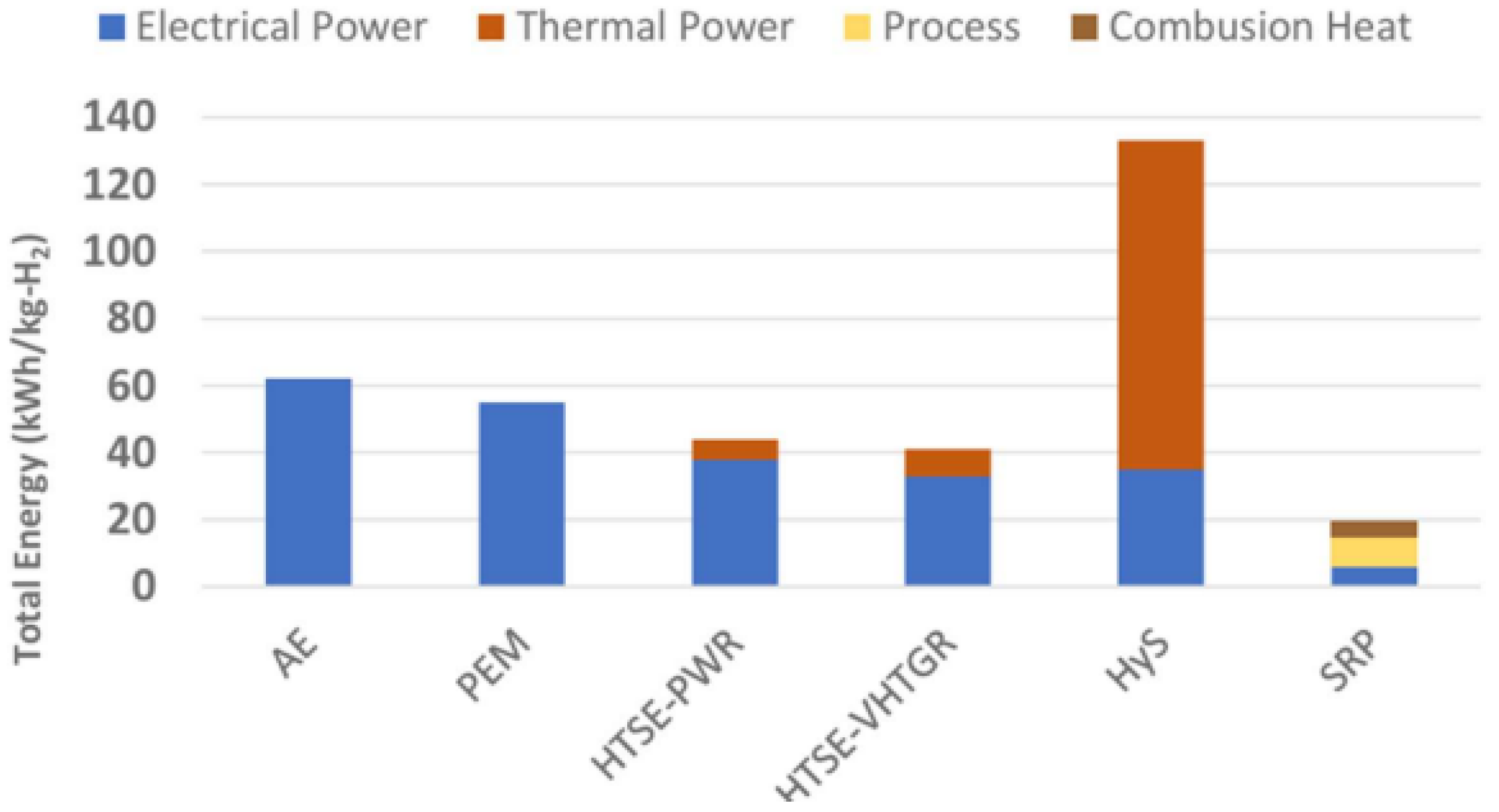
- (AE) Alkaline electrolysis
- (PEM) Proton-Exchange Membrane electrolysis
- (HTSE) High-Temperature Steam Electrolysis
- (SRP) Steam Reforming Process
- Safety and reliability, with a low likelihood and damage of reactor core damage.
- Economics, with a clear cost advantage and comparable financial risk to other energy sources and projects.
- Sustainability, with effective fuel utilization and reduction in nuclear waste, reduces long-term management burden.
- Proliferation resistance, being unattractive for diversion or theft of weapons-usable materials and increasing physical protection against terrorist attacks.
- Reactor Core: circular cylinder consisting of hexagonal fuel blocks, graphite guide blocks, and control rods; alternatively, graphite pebbles can be used instead of fuel blocks. The reactor core uses graphite as a moderator since it is suitable as a structural material because of its excellent properties, including high resistance to radiation, high heat resistance (with a sublimation temperature of about 3000 °C), and high thermal conductivity. The core of an HTR has a large thermal capacity, which helps ensure a high level of safety, as it can manage temperature rises without reaching critical conditions.
- Nuclear Fuel: depending on its shape, the HTR fuel can be classified as prismatic (block type or pin-in-block) or pebble-bed. In prismatic type fuel, a compact fuel containing fuel particles is inserted into a graphite sleeve. In pebble-bed type fuel, CFPs (coated fuel particles) are sintered into spherical form with a diameter of approximately 6 cm starting from a graphite-based matrix. The individual CFPs are of the TRISO type (tri-isotropic-coated particles) and have uranium oxide cores typically enriched to 6% by weight and a diameter of 600 μm, coated with layers of ceramic materials.
- Control system: the reactivity is controlled through the control rods (CR), which are inserted into the core guide columns and the reflector columns. A reserved shutdown system (RSS) is provided as an emergency shutdown system and works by inserting boron carbide/graphite pellets into the third channel of each control rod guide column. The neutron absorber is made of B4C and is coated with a cylindrical sheath nickel–iron–chromium alloy (800H-AT).
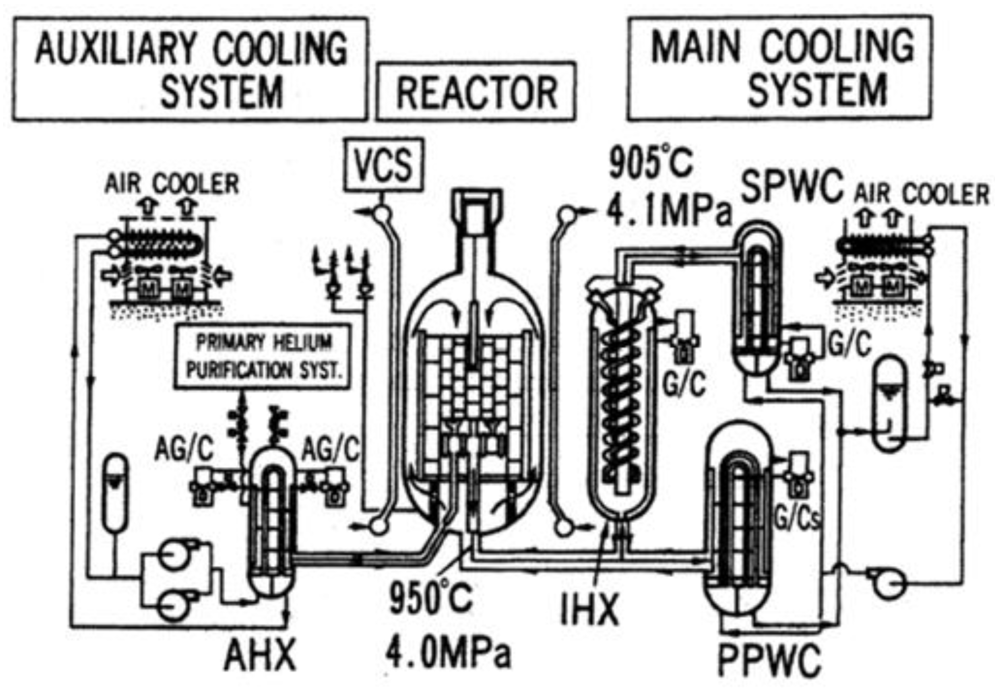
- Cooling system: helium was chosen as a coolant because it does not chemically react with the fuel and core structures. In this way, there is no need to consider the risks associated with instability situations when water is used as a coolant. Helium has minimal effects on neutron moderation and/or absorption and, therefore, does not influence the reaction in the core.
- -
- MCS main cooling system
- -
- ACS auxiliary cooling system
- Heat Exchangers/Steam Generator: Transfer the heat produced by nuclear fission to a secondary cycle.
- Containment System: designed to ensure safety; its purpose is to contain radioactive materials, prevent nuclear accidents, and maintain structural integrity.
- -
- The fuel coating
- -
- The RPV (reactor pressure vessel)
- -
- The CV (containment vessel)
- -
- The reactor building
- -
- containing fission products (FP) and preventing their release into the cooling system and the atmosphere
- -
- limiting the amount of air that can enter the core and react with the graphite present
- Intermediate Heat exchanger (IHX)
- Exchangers and Hydrogen Generation System
- -
- Separating the nuclear plant from the chemical plant
- -
- Eliminating the possibility of radioactive contamination in the final product
- -
- Preventing potential corrosion processes on the primary circuit side [11]
- -
- Facilitating maintenance and replacement of components in case of failure
- -
- Having a flexible design and managing hydrogen production
- -
- The exchanger operates at high temperatures
- -
- There are significant temperature differences and high pressures, which necessitate a careful selection of suitable materials

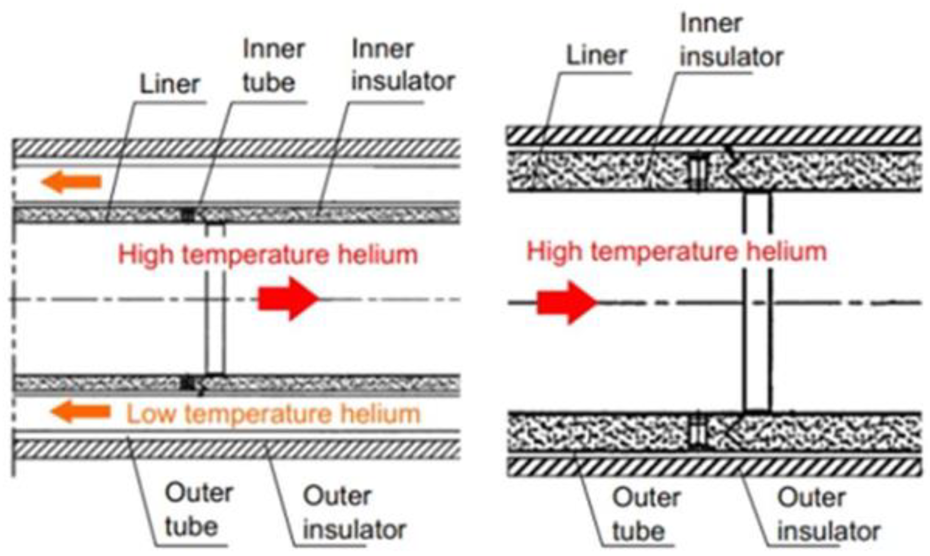
- A coaxial structure connecting the IHX to the primary exchanger (which varies depending on the type of production associated with the HTR)
- A single insulated duct for the secondary helium circuits
- Temperature → phase reactions
- Neutron irradiation → crystalline lattice damage, radiation effects
- Chemical conditions → formation of oxides/carbides
- Mechanical stress → thermal creep, plastic deformations, crack formation
- Thermal perturbation → reactor SCRAM
- Tritium permeation → radioactivity of the produced hydrogen
- -
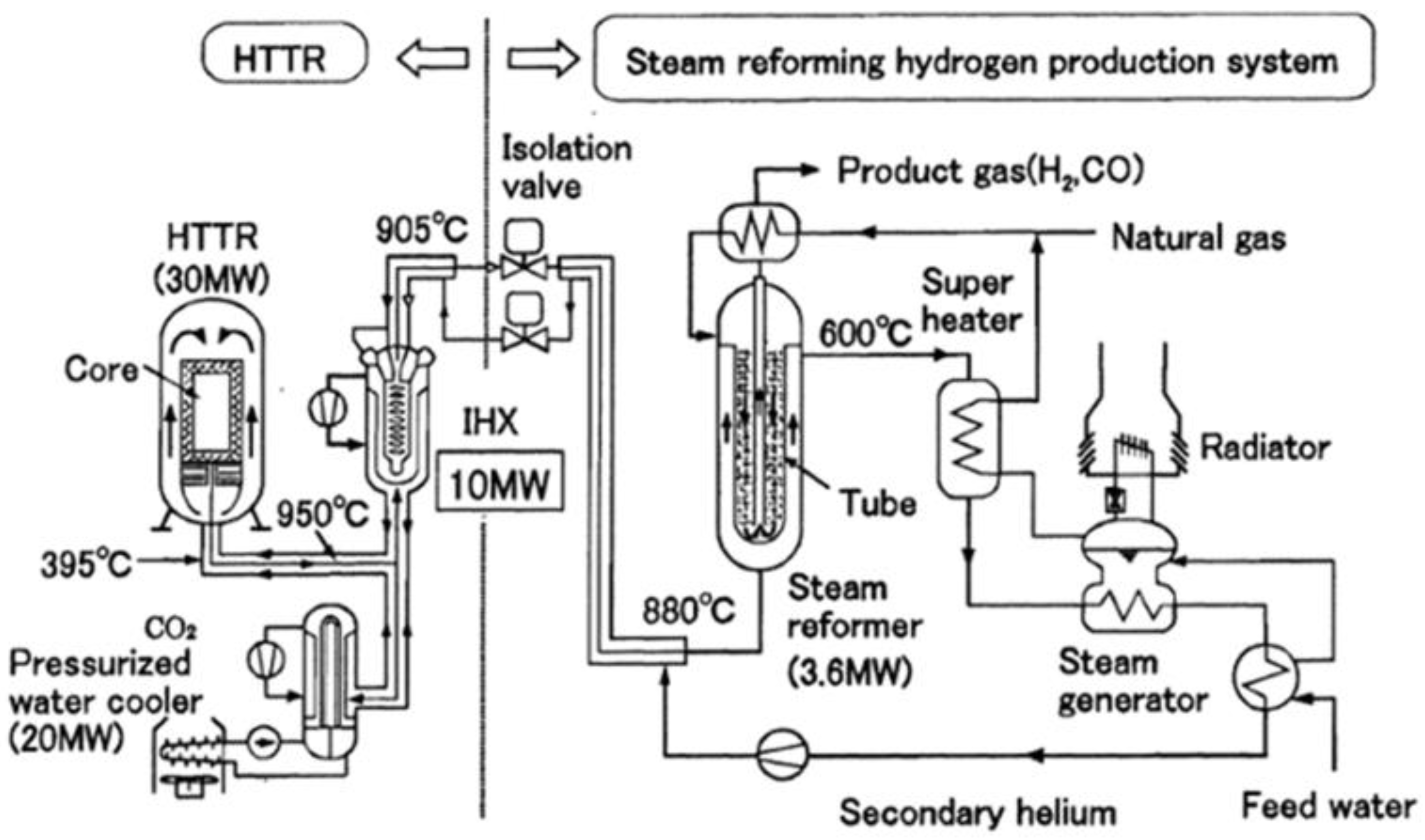
- A compact and high-performance steam reformer
- -
- Low heat losses in the hot gas duct installed between the reactor and the hydrogen production system
- -
- An emergency shut-off valve that can operate under high-temperature conditions in case of a radioactive release event in the reactor containment vessel
- -
- A hydrogen production rate greater than 4000 Nm3-STP/h
- -
- An overall efficiency of ~80%
2. Materials and Methods
2.1. FMEA and FTA Methods
- identifying and analyzing all potential failures associated with a system and assessing their effects;
- identifying the actions required to eliminate or significantly reduce the system failures and associated consequences;
- documenting the system from a functional point of view in the design and operating phase.
2.2. Operational Tree Computer Simulation
- physical nodes: these nodes represent the self-standing components whose failure rate is known.
- logical nodes: these nodes represent those components whose failure rate depends on that of the underlying sub-components. Logical node redundancy relations are set by a ratio, where indicates the number of sub-components that must be operative over the total number of sub-components.
- a constant value;
- a value function of either the clock time or the equivalent time;
- a function that depends on the status of other components whose malfunction may affect the failure rate of the component under examination (e.g., owing to vibrations);
- a mathematical formula indicating particular features of the component (e.g., good or bad installation) or the whole plant (e.g., favorable or unfavorable environment).
2.3. Operational Tree for the HTGR-SMR Plant
- The supply processes fundamental for the system’s correct operation have been schematized by a set of logical nodes, described in detail in Section 2.3.1.
- Each of said processes (logical nodes) is composed of sub-assemblies such as heat exchangers, pumps, blowers, and valves; the latter constitute the physical nodes of the operational tree and are characterized by a failure rate value. These sub-assemblies are described in detail in Section 2.3.2.
- The global failure rate for each sub-assembly has been calculated based on the failure rates of their elementary components, such as pipes, flanges, motors, actuators, etc. The elementary components failure rates have been calculated according to the guidelines provided in [22] in Section 2.3.3.
- This arrangement for the operational tree ensures to obtain, as a result of simulations, the failure attitude of each assembly, highlighting the systems that require more attention; moreover, it allows to focus on those elementary components that represent critical units for the system operation, so that the appropriate prevention actions (e.g., components redundancy rather than components modification) can be decided in the design phase.
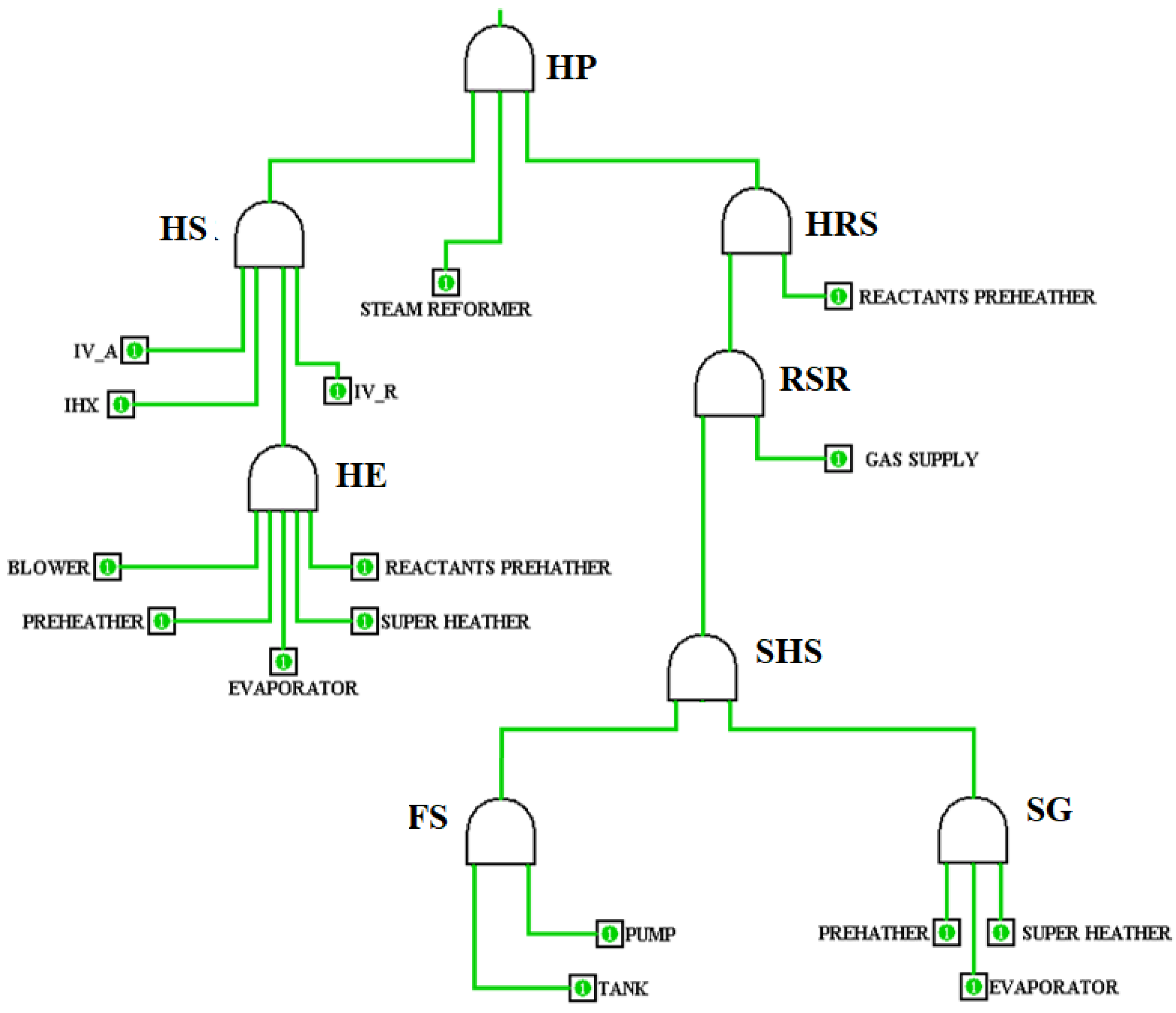
2.3.1. Plant Main Functions (Logical Nodes)
- Hydrogen production (HP): represents the upper-level logical node, i.e., the correct operation of the hydrogen production system. Following the sequence of these events, which, if verified, produce an interruption in hydrogen production, it can be stated that the functioning of this process is ensured by the availability of two processes, i.e., heated reactants supply (HRS in the following) and heat supply to process (HS in the following) and a physical component, i.e., the steam reformer.
- Heated reactants supply (HRS): represents the supply of reactants at the correct temperature to the steam reformer. Its functioning is ensured by the availability of the two reactant (steam and methane) supplies and the reactant pre-heaters.
- Heat supply to process (HS): represents the system ensuring the heat required by the steam reforming reaction and by the steam super-heating; such heat is made available by the secondary helium supply circuit, requiring the correct operation of the isolation valves on the supply (A) and return (R) lines and of the intermediate heat exchanger.
- Reactants supply to steam reformer (RSR): represents the supply of reactants; its functioning is ensured when both steam and methane supplies are available.
- Secondary helium supply (HE): represents the helium secondary circuit, ensuring the availability of the hot gas for heat supply. According to its assembly, this system’s availability is ensured by the correct operation of the physical components that constitute it, i.e., feedwater pre-heater, evaporator, super-heater, reactant pre-heaters, and helium circulation blower.
- Super-heated steam supply (SHS): represents the complex system dedicated to the supply of the super-heated steam. Its functioning is ensured by the availability of feedwater supply and steam generation.
- Feedwater supply (FS): provides the water for steam production and is composed of the feedwater storage tank and pump.
- Steam generation (SG): ensures the process of steam production by heat exchange with the helium; it is composed of three heat exchangers placed in series, i.e., feedwater pre-heater, evaporator, and super-heater.
2.3.2. Plant Sub-Assemblies (Physical Nodes)
- Heat exchanger: Pre-heater, evaporator, super-heater, reactant pre-heaters, and steam reformer, whose architecture is comparable to that of an ordinary heat exchanger; all of these assemblies are composed of welded tubes, flanges for input and output streams connection, and a shell (pressure vessel); the failure rate for the heat exchanger assembly appears in Equation (6).
- Helium Blower assembly: composed of a helium blower and motor. This component appears in the main helium circulation loop and the internal circulation loop of the IHX.
- Water Pump assembly: composed of a water pump and motor.
- Isolation valve (IV): composed of a valve and motor, both for the supply (A) and for the return (R) lines.
2.3.3. Elementary Components
- Tubeswhere:
- -
- = 0.47 f/106 h.
- -
- = 1.4: multiplying factor considering the stress applied to pipes, which is due to both high pressure and temperature
- Weldings
- Flangeswhere
- -
- = 2.4 f/106 h
- -
- = 0.25: multiplying factor considering fluid pressure.
- -
- = 5: multiplying factor considering allowable leakage; the value comes from the consideration that low fluid leakages are required for nuclear facilities.
- -
- = 39.3 (for helium); = 4.2 (for water/steam): multiplying factor considering flanges diameter.
- -
- = 1.4: multiplying factor considering fluid viscosity.
- -
- = 0.21: multiplying factor considering temperature variations in operation.
- Valveswhere:
- -
- = 1.25 f/106 h
- -
- = 0.1: multiplying factor considering operating pressure.
- -
- = 5.0: multiplying factor considering allowable leakage.
- -
- = 1.4: multiplying factor considering fluid viscosity.
- -
- = 0.42: multiplying factor considering valve contact pressure, determined on the basis of the valve diameter and operating conditions.
- -
- = 0.2: multiplying factor considering the size of the seat diameter of the valve.
- -
- = 0.8: multiplying factor considering the materials used.
- Pressure vessels (heat exchangers shell)
- Feedwater tank
- Blowers and pumpswhere
- -
- = 12.0 f/106 h fluid driver (impeller) failure rate.
- -
- : operating temperature multiplying factor.
- -
- = 0.010 f/106 h: stator casing failure rate.
- -
- = 34.66 f/106 h for helium blower; = 22.8 f/106 h for water pump: sealing failure rate.
- -
- = 0.23 f/106 h: shaft failure rate
- -
- = 15 f/106 h: bearing failure rate.
- Electric motorswhere:
- -
- = 10 f/106 h basic motor failure rate.
- -
- = 1 Motor load factor for load time variation; all motors have been considered operating at a steady state.
- -
- = 40 f/106 h: the failure rate of motor internal circuits.
- -
- = 0.001 f/106 h: stator casing failure rate.
- -
- = 22.8 f/106 h: shaft failure rate.
- -
- = bearings failure rate; considered equal as for pumps and blowers.
3. Results
3.1. Simulations Results
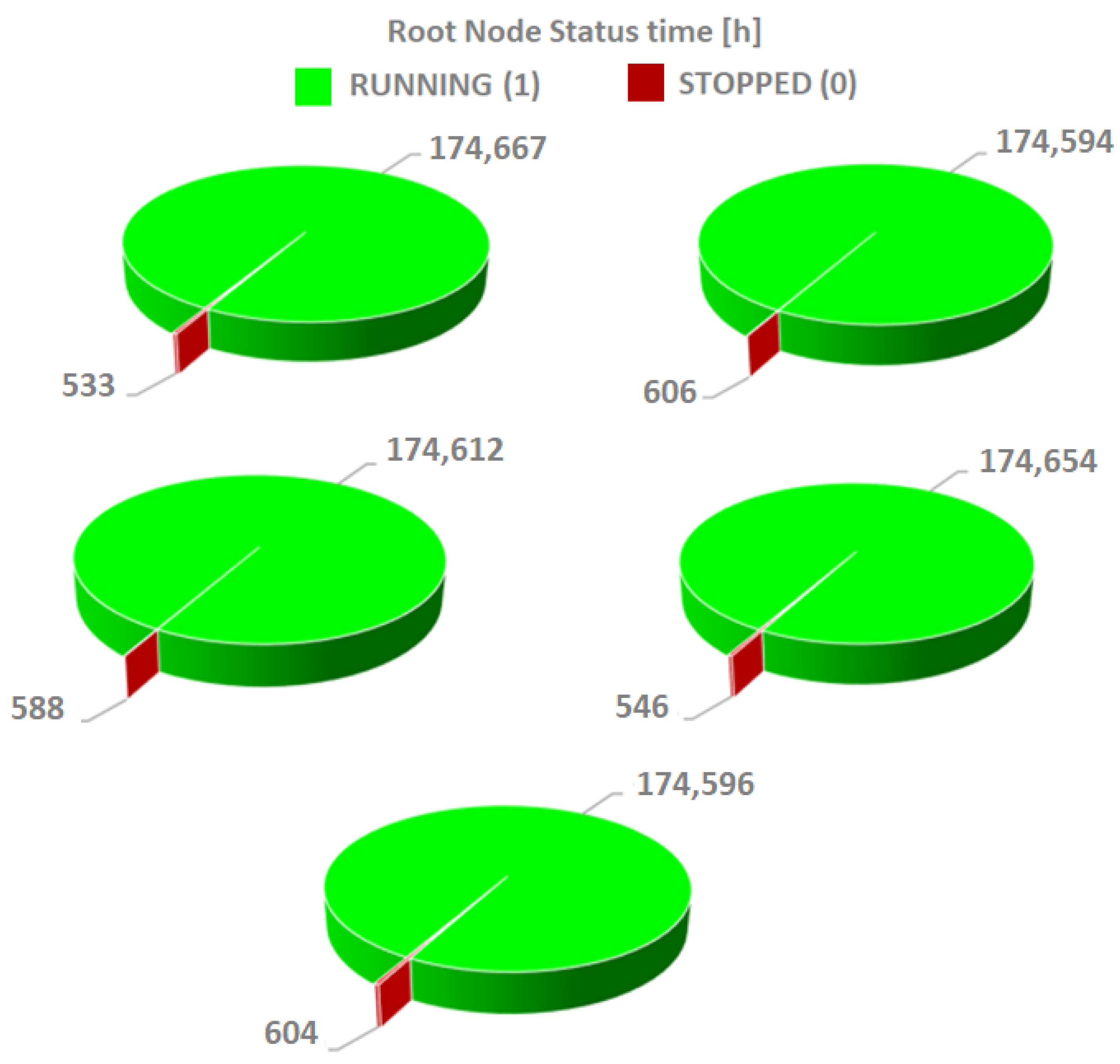
3.1.1. Plant Availability
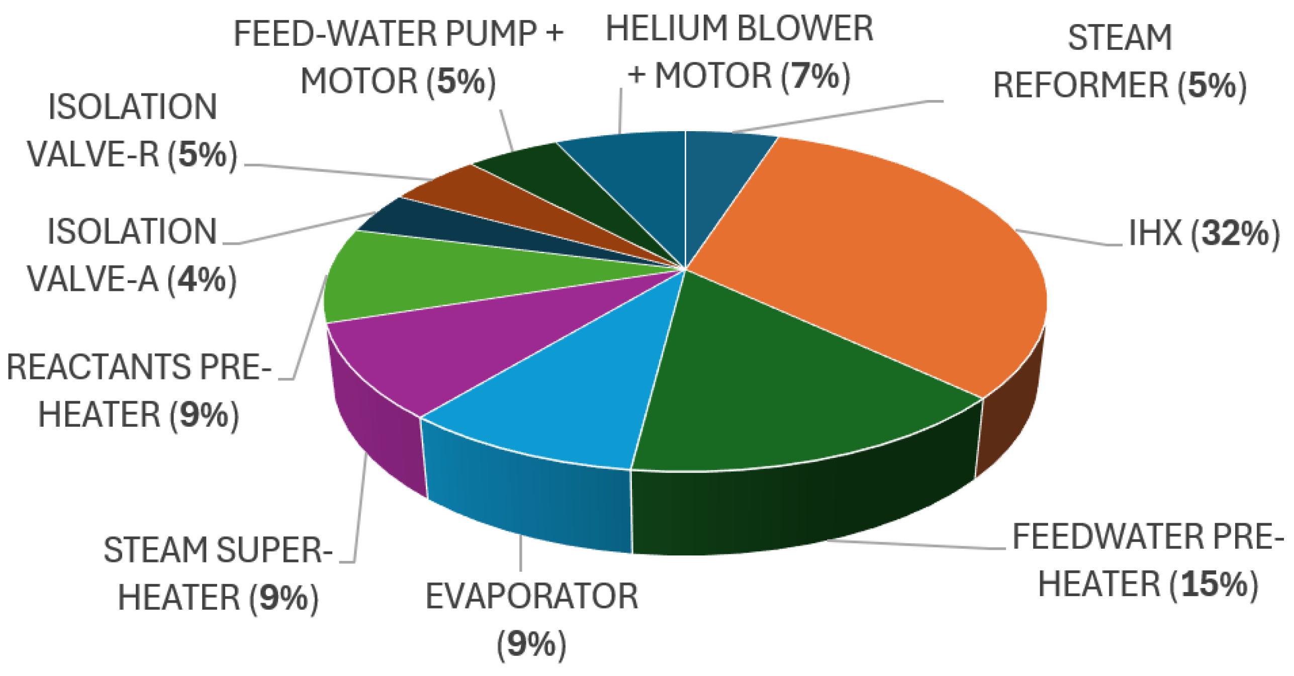
3.1.2. Main Components (Sub-Assemblies) Failure Breakdown
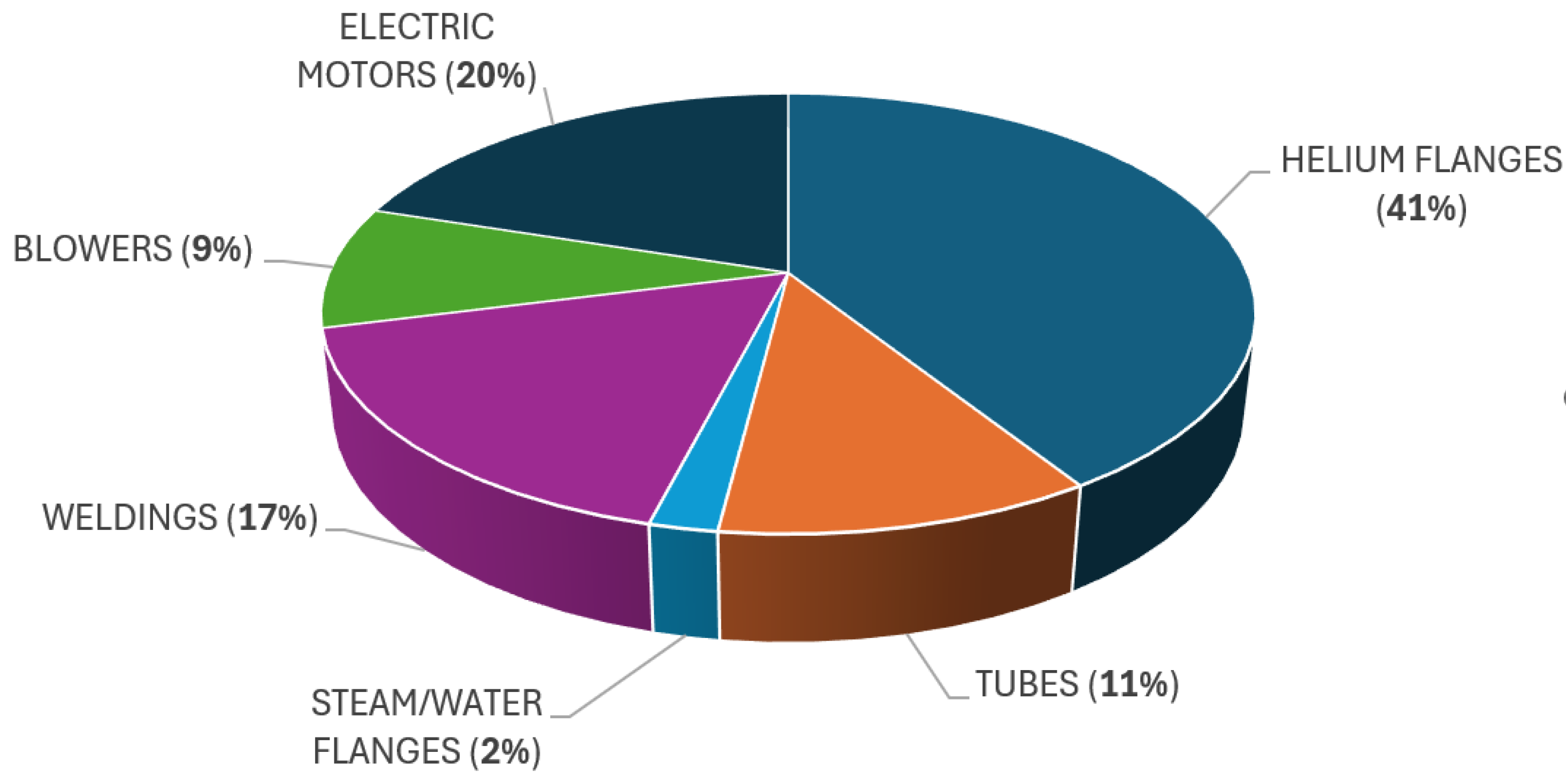
3.1.3. Elementary Components Failure Breakdown
4. Conclusions
- Modify the helium flanges in the IHX: such action would require a complete redesigning of the entire helium transport piping system, leading to disproportionate costs. The failure of the flanges result in helium gas leaks, which in themselves do not pose a problem, as helium is an inert gas with a low radioactive content due to tritium permeation (kept within permissible limits and thus not hazardous). The only issue related to helium leakage is the need for refilling, which leads to production downtime and cost.
- Provide redundancy for electric motors and machinery: The installation of two components in parallel would ensure, in case of one component failure, the immediate takeover by the other on standby. Redundancy would prevent failures, although requiring a significant financial investment.
- Since the IHX has shown to be the most critical single main assembly of the plant, development should focus on improving this component, by enhancing the materials used and increasing the quality controls on pipes and weldings. The IHX design associated with the HTTR includes an integrated recirculation blower with the function of transferring helium between two heat exchanging bundles. A possible modification might involve the installation of this recirculation loop outside the IHX shell, providing an insulated connection to prevent leaks; this would make it possible to provide redundancy for blowers and motors, which, as stated, are responsible for almost 20% of IHX failures.
Author Contributions
Funding
Data Availability Statement
Conflicts of Interest
References
- Hussein, H.; Schuetze, B. Risks of Morocco’s green hydrogen plans. Science 2024, 386, 501–502. [Google Scholar] [CrossRef] [PubMed]
- Bolfo, L.; Devia, F.; Lomonaco, G. Nuclear Hydrogen Production: Modeling and Preliminary Optimization of a Helical Tube Heat Exchanger. Energies 2021, 14, 3113. [Google Scholar] [CrossRef]
- Campos, W. Hydrogen Fuel Cell Engines and Related Technologies, Module 1: Hydrogen Properties. Hydrogen Fuel Cell Engines. College of the Desert. 2001. Available online: https://www.energy.gov/sites/default/files/2014/03/f12/fcm01r0.pdf (accessed on 26 March 2025).
- Watanabe, C. MITI’s New Comprehensive Approach to Energy and Environmental Technologies: The New Sunshine Program. In Proceedings of the 7th Japanese French Expert Meeting on Energy and Environmental Technologies, Tokyo, Japan, 31 May–1 June 1993. [Google Scholar]
- Ritchie, H.; Roser, R. Emissions by Sector, Our World in Data CO2 and Greenhouse Gas Emissions Database. 2020. Available online: https://ourworldindata.org/emissions-by-sector (accessed on 26 March 2025).
- Cerullo, N.; Lomonaco, G. Generation IV reactor designs, operation and fuel cycle. Nucl. Fuel Cycle Sci. Eng. 2012, 333–395. [Google Scholar] [CrossRef]
- Carapellucci, R.; Giordano, L. Steam, Dry, and Autothermal Methane Reforming for Hydrogen Production: A Thermodynamic Equilibrium Analysis. J. Power Sources 2020, 469, 228391. [Google Scholar] [CrossRef]
- Japan Atomic Energy Research Institute. Present Status of HTGR Research and Development; Japan Atomic Energy Research Institute: Tokai, Japan, 1996.
- Al-Shikh, S.A.; Al-Ammar, E.A.; Alomari, A.S. Economic Feasibility of Hydrogen Generation Using HTR-PM Technology in Saudi Arabia. Sustainability 2025, 17, 1730. [Google Scholar] [CrossRef]
- Yan, X.L.; Kasahara, S.; Tachibana, Y.; Kunitomi, K. Study of a nuclear energy supplied steelmaking system for near-term application. Energy 2012, 39, 154–165. [Google Scholar] [CrossRef]
- Cerullo, N.; Lomonaco, G. Corrosion Issues in High Temperature Gas-Cooled Reactor (HTR) Systems. In Nuclear Corrosion Science and Engineering; Woodhead Publishing: Cambridge, UK, 2012; pp. 731–772. [Google Scholar] [CrossRef]
- Saito, S. High Temperature Applications of Nuclear Energy. In Present Status of the HTTR Project at JAERI; IAEA-TECDOC-761; IAEA: Vienna, Austria, 1994; pp. 11–19. [Google Scholar]
- Cleveland, J.; Lewkowicz, I. Status of the IAEA Coordinated Research Programme on Design and Evaluation of Heat Utilization Systems for the HTTR. In Proceedings of the 2nd International Conference on Multiphase Flow, Kyoto, Japan, 3–7 April 1995. [Google Scholar]
- van den Bosch, C.J.H.; Weterings, R.A.P.M. Methods for the Calculation of Physical Effects—‘Yellow Book’ CPR 14E, 3rd ed.; Committee for the Prevention of Disasters: The Hague, The Netherlands, 1997. [Google Scholar]
- Zafiropoulos, M.E.P.; Dialynas, E.N. Reliability prediction and failure mode effects and criticality analysis (FMECA) of electronic devices using fuzzy logic. Int. J. Qual. Reliab. Manag. 2005, 22, 183–200. [Google Scholar] [CrossRef]
- Damiani, L.; Giribone, P.; Revetria, R.; Testa, A. An Innovative Model for Supporting FMEA/FMECA Analysis on Coal-Fired Power Plants. In Proceedings of the IASTED International Conference Modelling, Identification and Control (MIC 2014), Innsbruck, Austria, 17–19 February 2014. [Google Scholar]
- Krasich, M. Use of Fault Tree Analysis for Evaluation of System-Reliability Improvements in Design Phase. In Proceedings of the Annual Reliability and Maintainability Symposium. International Symposium on Product Quality and Integrity (Cat. No.00CH37055), Los Angeles, CA, USA, 24–27 January 2000; IEEE: New York, NY, USA, 2000. [Google Scholar]
- Revetria, R.; Bruzzone, A.G. Reliability Analysis by Using Simulation for Complex Automated Plants. Int. J. Simul. Ser. 1999, 34, 115–119. [Google Scholar]
- Briano, E.; Caballini, C.; Giribone, P.; Revetria, R. Two methodologies to support gas turbine power plant availability estimation: Design of experiment and Montecarlo simulation. WSEAS Trans. Syst. 2010, 9, 1109–2777. [Google Scholar]
- Cassettari, L.; Mosca, R.; Revetria, R. Monte Carlo Simulation Models Evolving in Replicated Runs: A Methodology to Choose the Optimal Experimental Sample Size. Math. Probl. Eng. 2012, 2012, 463873. [Google Scholar] [CrossRef]
- Bruzzone, A.G.; Revetria, R.; Briano, E. Design of Experiment and Monte Carlo Simulation as Support for Gas Turbine Power Plant Availability Estimation. In Proceedings of the 22nd IASTED International Conference on Modelling, Identification, and Control (MIC 2003), Innsbruck, Austria, 10–13 February 2003. [Google Scholar]
- NSWC. Handbook of Reliability Prediction Producers for Mechanical Equipment; NSWC: Bethesda, MY, USA, 2011. [Google Scholar]
- Cadwallader, L.C. Failure Rate Estimates for Passive Mechanical Components; OSTI.GOV: Oak Ridge, TN, USA, 2018. [CrossRef]

| Containment | Material | Maximum Allowable Temperature |
|---|---|---|
| CV | SUS316 | 150 °C |
| RPV | 2.25Cr-1Mo Steel | 440 °C |
| HTTR | |
|---|---|
| Thermal power | 30 MW |
| Coolant | Helium |
| Helium Core outlet coolant temperature | 850/950 °C |
| Core inlet coolant temperature Fuel | 395 °C |
| Fuel | Low-enriched UO2 |
| Fuel element type | Prismatic block |
| Direction of coolant flowing through the core | Downward |
| Pressure vessel material | Steel |
| Number of main cooling loops | 1 |
| Heat removal system | Pressurized water cooler and IHX |
| Primary coolant pressure | 4 MPa |
| Containment vessel | Steel containment |
| Plant lifetime | 20 years |
| IHX | |
|---|---|
| Design shell pressure | 4.81 MPa |
| Design tube pressure | 0.29 MPa |
| Design shell temperature | 430° C |
| Design tube temperature | 955° C |
| Primary helium (shell side) inlet temperature | 850–950 °C |
| Primary helium (shell side) outlet temperature | 389 °C |
| Primary helium (shell side) inlet pressure | 4.06 MPa |
| Primary helium (shell side) pressure drop | 1 kPa |
| Flow rate | 3.4 kg/s |
| Secondary helium inlet temperature | 270 °C |
| Secondary helium outlet temperature | 775–860 °C |
| Secondary helium inlet pressure | 4.21 MPa |
| Secondary helium pressure drop | 20 kPa |
| Secondary helium flow rate | 3.0 kg/s |
| Design lifetime | 20 years |
| SR | |
|---|---|
| Thermal power | 10 MW |
| Secondary helium inlet temperature | 880 °C |
| Secondary helium outlet temperature | 600 °C |
| Secondary helium flow rate | 25 kg/s |
| SRP | |
|---|---|
| Secondary Helium flow rate | 9070 kg/h |
| Secondary Helium temperature: | |
| Outlet/Inlet of the IHX | 905/160 °C |
| Outlet/Inlet of the SR | 880/600 °C |
| Outlet/Inlet of the SG | 555/275 °C |
| Pressure | 4.1 MPa |
| Process feed gas flow rate | 6450 kg/h |
| Methane | 1290 kg/h |
| Steam | 5160 kg/h |
| Process feed gas composition: | |
| CH4 | 17.7 mol% |
| C2H6 | 1.2 mol% |
| C3H8 | 0.6 mol% |
| C4H10 | 0.3 mol% |
| H2O | 80.2 mol% |
| Process feed gas pressure | 4.5 MPA |
| Product gas Composition: | |
| H2 | 38.7 mol% |
| CO | 4.7 mol% |
| CO2 | 5.7 mol% |
| CH4 | 5.1 mol% |
| H2O | 46.0 mol% |
| Product gas pressure | 4.1 MPa |
| Failure Rate of Elementary Components | |
|---|---|
| Tube | 34.66 |
| Welding | 1 |
| Flange, helium | 3.07 |
| Flange, steam | 0.06 |
| Valve | 0.06 |
| Pressure vessel (Shell) | 0.001 |
| Water pump | 50.4 |
| Helium blower | 66.70 |
| Motor | 76.00 |
| Failure Rate of Sub-Assemblies | |
|---|---|
| IHX | 544.5 |
| Pre-heater | 148.4 |
| Evaporator | 92.0 |
| Super-heater | 108.6 |
| Reactant pre-heaters | 108.6 |
| Steam reformer | 178.3 |
| Isolation valve | 76.0 |
| Component | Averaged Failures Number |
|---|---|
| Steam Reformer | 29.2 |
| IHX | 183.6 |
| Feedwater Pre-heater | 83.6 |
| Evaporator | 50.8 |
| Super-heater | 53.4 |
| Reactant Pre-heaters | 54.2 |
| Isolation Valve_A | 25.4 |
| Isolation Valve_R | 29 |
| Feedwater Pump | 27 |
| Helium Circulation Blower | 39.2 |
| Total failures | 575.4 |
| Mean Time Between Failures | 304.4 [h] |
| Main Assembly | Elementary Component | Failure % |
|---|---|---|
| Helium flanges | 35.6 | |
| Steam Flanges | 2.7 | |
| Tubes | 27.4 | |
| Weldings | 34.2 | |
| Shell | 0.0 | |
| IHX | Flanges | 43.9 |
| Tubes | 12.5 | |
| Weldings | 17.2 | |
| Shell | 0.0 | |
| Blower | 12.6 | |
| Blower Motor | 13.7 | |
| Feedwater Pre-Heater | Helium Flanges | 46.2 |
| Water Flanges | 5.7 | |
| Tubes | 17.7 | |
| Weldings | 30.4 | |
| Shell | 0.0 | |
| Evaporator | Helium Flanges | 73.2 |
| Steam Flanges | 4.7 | |
| Tubes | 6.3 | |
| Weldings | 15.7 | |
| Shell | 0.0 | |
| Super-Heater | Helium Flanges | 60.7 |
| Steam Flanges | 5.2 | |
| Tubes | 12.4 | |
| Weldings | 21.7 | |
| Shell | 0.0 | |
| Reactant Pre-Heaters | Helium Flanges | 70.1 |
| Reactants Flanges | 1.8 | |
| Tubes | 10.3 | |
| Weldings | 17.3 | |
| Shell | 0.4 | |
| Isolation Valve-A | Valve assembly | 0.0 |
| Valve motor | 100.0 | |
| Isolation valve-R | Valve assembly | 0.0 |
| Valve motor | 100.0 | |
| Feedwater Pump | Pump assembly | 43.7 |
| Electric motor | 56.3 | |
| Secondary Helium Circulation Blower | Blower Assembly | 48.0 |
| Blower electric motor | 52.0 |
Disclaimer/Publisher’s Note: The statements, opinions and data contained in all publications are solely those of the individual author(s) and contributor(s) and not of MDPI and/or the editor(s). MDPI and/or the editor(s) disclaim responsibility for any injury to people or property resulting from any ideas, methods, instructions or products referred to in the content. |
© 2025 by the authors. Licensee MDPI, Basel, Switzerland. This article is an open access article distributed under the terms and conditions of the Creative Commons Attribution (CC BY) license (https://creativecommons.org/licenses/by/4.0/).
Share and Cite
Damiani, L.; Novarini, F.; Lomonaco, G. An FMEA Assessment of an HTR-Based Hydrogen Production Plant. Energies 2025, 18, 2137. https://doi.org/10.3390/en18082137
Damiani L, Novarini F, Lomonaco G. An FMEA Assessment of an HTR-Based Hydrogen Production Plant. Energies. 2025; 18(8):2137. https://doi.org/10.3390/en18082137
Chicago/Turabian StyleDamiani, Lorenzo, Francesco Novarini, and Guglielmo Lomonaco. 2025. "An FMEA Assessment of an HTR-Based Hydrogen Production Plant" Energies 18, no. 8: 2137. https://doi.org/10.3390/en18082137
APA StyleDamiani, L., Novarini, F., & Lomonaco, G. (2025). An FMEA Assessment of an HTR-Based Hydrogen Production Plant. Energies, 18(8), 2137. https://doi.org/10.3390/en18082137