Article

An Improved Dynamic Matrix Control Algorithm and Its Application in Cold Helium Temperature Control of a Modular High-Temperature Gas-Cooled Reactor (mHTGR)

1
Institute of Nuclear and New Energy Technology, Collaborative Innovation Centre of Advanced Nuclear Energy Technology, Key Laboratory of Advanced Reactor Engineering and Safety of Ministry of Education, Tsinghua University, Beijing 100084, China
2
Huaneng Nuclear Energy Technology Research Institute, Shanghai 200126, China
*
Author to whom correspondence should be addressed.
Energies 2025, 18(9), 2145; https://doi.org/10.3390/en18092145
Submission received: 28 February 2025 / Revised: 11 April 2025 / Accepted: 21 April 2025 / Published: 22 April 2025
(This article belongs to the Special Issue New Challenges in Safety Analysis of Nuclear Reactors)

Abstract

:
As a model predictive control (MPC) technique, dynamic matrix control (DMC) has gained widespread industrial adoption due to its straightforward model construction and clear physical interpretation. However, its effectiveness relies on the accuracy of the predictive model, where measurement inaccuracies or excessive noise in step-response coefficients may significantly degrade control performance. This study enhances robustness of DMC by implementing finite impulse response (FIR) filters on measured step-response coefficients while providing theoretical proof of its stability. The improved algorithm is applied to cold helium temperature control of the modular High-Temperature Gas-Cooled Reactor (mHTGR). A cascade control structure is adopted, where the inner loop uses a PID controller to ensure system stability, while the outer loop uses DMC to adjust the setpoint of the hot helium temperature, thereby controlling the cold helium temperature. Numerical simulation results demonstrate significant improvements in temperature control performance and enhanced robustness of the modified DMC method.

1. Introduction

Dynamic matrix control (DMC), as a prominent subclass of model predictive control (MPC), has maintained widespread industrial adoption since its seminal development by Cutler and Ramaker in 1980 [1]. The algorithm’s fundamental principle employs a step-response-based prediction model to optimize control inputs over finite horizons, effectively balancing computational efficiency with process adaptability—particularly advantageous for linear time-invariant systems [2,3]. Distinctive features including minimal hyperparameter requirements, strong physical interpretability, high computational throughput, real-time implementation capability, and operational robustness in complex industrial settings [4] have driven its successful deployment across chemical engineering processes [5], power generation systems [6], and nuclear reactor control architectures [7].
Through four decades of evolution, DMC methodologies have progressively addressed emerging industrial complexities. Initial developments focused on nonlinear system adaptations, where Townsend and Zhao [8,9] pioneered nonlinear model integration within the DMC framework to enhance operational flexibility. Subsequent advancements by Lee et al. [10] introduced state-space formulations, significantly improving robustness in large-scale system applications. Jiang et al. [11] achieved concurrent system stabilization and transient performance optimization through novel cascaded DMC-PID control structures. Adaptive strategies [12] and data-driven DMC approaches by Xu et al. [13] addressed model uncertainties. Hybrid implementations combining DMC with sliding mode control [14], fuzzy logic systems [15,16], and neural network architectures [17] have further extended its applicability to nonlinear dynamic systems with parametric uncertainties. For complex large-scale systems, distributed DMC has emerged as a critical strategy, where systems are decomposed into subsystems with localized DMC implementations [18]. Wang et al. [19] advanced this paradigm by proposing a fractional-order modeling-based DMC framework, offering theoretical insights for extending conventional integer-order DMC to fractional-order systems. Their work further incorporated PID-type compensation operators into the cost function to simultaneously optimize setpoint tracking and disturbance rejection capabilities. Building on this foundation, Teng et al. [20] developed a distributed fractional-order PID-type DMC algorithm, leveraging Nash optimization theory to systematically decouple subsystem interactions. To address computational challenges in constrained DMC implementations, Zou et al. [21] introduced a relaxation factor into the quadratic programming formulation, significantly enhancing algorithmic efficiency while maintaining stability guarantees. Concurrently, Krener et al. [22] pioneered adaptive time-domain MPC, which dynamically adjusts prediction horizon lengths to achieve control objectives within minimal time windows, thereby reducing computational burdens in real-time applications.
Despite these advancements, the performance of DMC remains fundamentally on the accuracy of its prediction model. Conventional DMC assumes precise measurement of step-response coefficients, yet these coefficients are often corrupted by noise or disturbances in practice. Such model–plant mismatches may induce oscillatory behavior or even instability, particularly in safety-critical systems like nuclear reactors. While Jiang et al. [23,24] mitigated high-frequency noise in step-response matrices via singular value decomposition (SVD) truncation, this approach risks discarding essential dynamic modes. Ma et al. [25] addressed the robust stability problem of single-input single-output (SISO) dynamic matrix control by characterizing model uncertainty through variation bounds of process step responses and derived sufficient conditions for system stability using Jury’s theorem. They proposed a robust enhancement strategy through the introduction of a polynomial-form mismatch filter, which effectively expands the robust stability domain. García et al. [26] enhanced robustness by decoupling DMC into predictive and feedback-correction modules, demonstrating that first-order filtering of feedback coefficients improves algorithmic resilience. For processes with integral and unstable dynamics, Tito et al. [27] enhanced algorithm stability by applying a filter to the model prediction error, enabling direct application of the DMC algorithm to open-loop unstable processes. Xing et al. [28] improved control accuracy near steady-state by implementing time-varying feedback correction gains. Xu et al. [13] addressed model mismatch by minimizing the discrepancy between the auto-covariance matrices of predicted outputs and actual output samples. When predictive models are challenging to establish, integration with adaptive methods becomes viable. Tohidi et al. [29] proposed an adaptive model predictive control approach for building thermal dynamics, incorporating real-time parameter identification to update predictive model parameters. Li et al. [30] developed an adaptive integral sliding mode-based predictive model for simultaneous control of motor speed and current.
Existing studies predominantly focus on feedback correction or external control integration, yet they inadequately address the root cause of noise-corrupted step-response coefficients. This study proposes a refined DMC algorithm incorporating finite impulse response (FIR) filtering to preprocess measured step-response coefficients. Unlike prior methods, the proposed approach directly attenuates measurement noise while preserving critical system dynamics. Rigorous stability analysis via Jury’s criterion ensures robustness without complex model reconfiguration [31].
The improved DMC is integrated into a cascade control architecture for cold helium temperature regulation in a modular High-Temperature Gas-Cooled Reactor (mHTGR). Here, an inner-loop PID ensures baseline stability, while the outer-loop DMC optimizes hot helium temperature setpoints to regulate cold helium temperature. Numerical simulations validate the algorithm’s efficacy under noisy conditions, demonstrating superior performance in safety-critical nuclear applications.

2. Design of Dynamic Matrix Controller

Starting from the step response of the controlled object, the dynamic characteristics of the system are described by a series of dynamic response values, S u = [ s 1 s 2 s p ] T , i.e., the unit step response values at the sampling instants. Let p denote the model’s time domain length, and s p represent a convergence coefficient approaching the steady-state value. According to the proportionality and superposition properties of linear systems (the principle of invariant coefficients), if an input u(ki) is applied at a certain time ki, the contribution of the change Δu(ki) to the output y(k) can be expressed as follows:
y ( k ) = s i Δ u ( k i ) ( 1 i < p ) s p Δ u ( k i ) ( i p )
Following a sufficiently long duration after the step change, the system’s response curve becomes approximately linear. For integral-type systems, after N sampling periods—when the slope of the step response curve stabilizes—the system is considered to attain steady-state operation, as depicted in Figure 1. Subsequent state variables may then be expressed as follows:
y ( k + N ) = 2 y ( k + N 1 ) y ( k + N 2 )
The state variable at time k is defined as follows:
Y ( k ) = [ y ( k ) , y ( k + 1 ) , , y ( k + N 1 ) ] T Δ u ( k + i ) = 0 , i = 0 , 1 , , N 1
According to the superposition principle, the system’s response to any input variation with a non-zero initial state is given by the following:
Y ( k ) = M s s Y ( k 1 ) + S u Δ u ( k 1 ) y ( k ) = C Y ( k )
where C = [ 1 0 0 ] 1 × N , M s s = 0 1 0 0 0 0 0 1 0 0 0 0 0 0 1 0 0 0 1 2 N × N .
Since not all states of the unit step response model are measurable (only the first component is measurable), it is necessary to estimate the unmeasurable states. The estimated states are then used as initial conditions to predict the system’s future dynamics. The design of the state observer equation is as follows:
Y ˜ ( k ) = M ss Y ˜ ( k 1 ) + S u Δ u ( k 1 ) + K F ( y ( k 1 ) C Y ˜ ( k 1 ) )
Define: Y P ( k + 1 | k ) = d e f y ( k + 1 | k ) y ( k + 2 | k ) y ( k + p | k ) p × 1 , Δ U ( k ) = d e f Δ u ( k ) Δ u ( k + 1 ) Δ u ( k + m 1 ) m × 1 .
The prediction of the system’s future output over p steps can be computed using the following prediction equation [23]:
Y p ( k + 1 | k ) = M Y ˜ ( k ) + A Δ U ( k )  
where M = C M s s C M s s 2 C M s s p = M s s ,
A = C S u 0 0 0 C M s s S u C S u 0 0 C M s s m 1 S u C M s s m 2 S u C S u C M s s p 1 S u C M s s p 2 S u C M s s p m S u p × m = s 1 0 s 2 s 1 s m s m 1 s 1 s p s p 1 s p m .
Objective Function: min Δ U ( k ) J ( Y p ( k + 1 | k ) , Δ U ( k ) , m , p ) .
J ( Y p ( k + 1 | k ) , Δ U ( k ) , m , p ) = | | Q ( Y p ( k + 1 | k ) R ( k + 1 ) ) | | 2 + | | λ Δ U ( k ) | | 2
Let J Δ U = 0 ,
Δ U ( k ) = ( A T Q A + λ ) 1 A T Q ( R ( k + 1 ) M Y ˜ ( k ) )
When applied to the controlled object, only the first component of the optimal control law is introduced into the system at each step.
Δ u ( k ) = K mpc ( R ( k + 1 ) M Y ˜ ( k ) )
where K mpc = C T ( A T Q A + λ ) 1 A T Q , C = [ 1 0 0 ] 1 × N .

3. Stability Analysis and Improvement

3.1. Proof of Stability

Considering the influence of noise, disturbances, and other factors in practical processes, the measurement of step response coefficients may not be accurate, leading to the potential mismatch of the predictive model. The uncertainty of the system is defined as follows:
Ω = { s | s i s i s i , i = 1 , N }
In the equation, s i and s i represent the lower and upper bounds of the fluctuations in the step response coefficients, respectively. The actual step response coefficient { s i } ( i = 1 , 2 , , N ) and the measured step response coefficient {   s   ˜ i } ( i = 1 , 2 , , N ) satisfy the following condition is as follows:
s i s i s i
s i s ˜ i s i
The total mismatch of the model can be expressed as follows:
M = i = 1 N | s i s ˜ i |
From Equation (4), the predicted output at time k + j is as follows:
y ˜ k + j = y ˜ k + j f u + y ˜ k + j p + y k y ˜ k
where
y k = i = 1 N 1 s i Δ u ( k i ) + s N u ( k N ) y ˜ k = i = 1 N 1 s ˜ i Δ u ( k i ) + s ˜ N u ( k N ) y ˜ k + j f u = i = 1 j s ˜ i Δ u ( k + j i ) y ˜ k + j p = i = j + 1 N 1 s ˜ i Δ u ( k + j i ) + s ˜ N u ( k + j N )
From Equation (9), it can be seen that the optimal control increment at the current time step is as follows:
Δ u ( k ) = j = 1 p k 1 j e ^ k + j
where
e ^ k + j = r k + j y ˜ k + j p y k + y ˜ k
k 1 j is the j-th column of [ K mpc ] 1 × p = C T ( A T Q A + R ) 1 A T Q . Substituting Equation (17) into Equation (16) and rearranging the terms, we obtain the following:
1 z 1 j = 1 p k 1 j ( i = 1 N s j i z i ) u k = j = 1 p k 1 j r k + j
where
s j 1 = s ˜ 1 s 1 s ˜ 1 + j s j i = s ˜ i s i ( s ˜ i 1 s i 1 ) + s ˜ i + j 1 s ˜ i + j = δ s i δ s i 1 + s ˜ i + j 1 s ˜ i + j , ( 2 i N j ) s j i = s ˜ i s i ( s ˜ i 1 s i 1 ) = δ s i δ s i 1 , ( N j + 1 i N ) δ s i = s ˜ i s i
From Equation (18), it can be seen that the characteristic polynomial of the controller is as follows:
f ( z ) = z N ( 1 + j = 1 p k 1 j s j 1 ) z N 1 i = 2 N ( j = 1 p k 1 j s j i ) z N i
Theorem 1.
For an open-loop stable system, let the actual step response coefficient and the measured step response coefficient satisfy Equations (11) and (12), respectively. Then, when
| 1 j = 1 p k 1 j s ˜ 1 + j | + i = 2 N j j = 1 p | k 1 j ( s ˜ i + j 1 s ˜ i + j ) | + 2 j = 1 p | k 1 j | M < 1
the closed-loop system is robustly stable.
Proof of Theorem 1.
From Equation (21), it can be inferred that
| 1 j = 1 p k 1 j s ˜ 1 + j | + i = 2 N j j = 1 p | k 1 j ( s ˜ i + j 1 s ˜ i + j ) | + j = 1 p | k 1 j δ s 1 | + j = 1 p | k 1 j | ( i = 2 N | δ s i | ) + j = 1 p | k 1 j | ( i = 2 N | δ s i 1 | ) < 1
| 1 + j = 1 p k 1 j ( δ s 1 s ˜ 1 + j ) | + j = 1 p | k 1 j | i = 2 N j | δ s i δ s i 1 + s ˜ i + j 1 s ˜ i + j | + i = N j + 1 N | δ s i δ s i 1 | < 1
| 1 + j = 1 N k 1 j s j 1 | + i = 2 N | j = 1 p k 1 j s j i ) | < 1
Since the open-loop system is stable, and combining Equation (20) with the Jury’s criterion [25], it can be concluded that the closed-loop system is robustly stable. Hence, the proof is completed. □

3.2. Robustness Improvement

From the above theorem, it can be concluded that to ensure the stability of the control algorithm, the total model mismatch, M , must be kept within a certain range. Previously, Jiang et al. [23,24] proposed that robustness could be improved through SVD. The specific implementation is as follows. Perform SVD on the dynamic matrix: A = U Σ V T , by truncating the singular values, i.e., selecting the first m columns of the matrix U , V and the first m singular values, a new matrix A m = U m Σ m V m T is formed. At this point, the gain of the dynamic matrix control law becomes the following:
K mpc = C [ ( A m T Q A m + P ) 1 A m T Q ]
Since the dynamic matrix is reconstructed from step response coefficient vectors, direct truncation of its singular values with a fixed threshold risks losing critical system dynamics due to the lack of adaptive threshold adjustment. A more robust approach involves applying filtering directly to the step response coefficient vectors, where window functions smooth measurement noise while preserving essential dynamic characteristics. Common denoising methods include infinite impulse response (IIR) filtering, wavelet transforms, and Kalman filtering. Although IIR filtering achieves high computational efficiency (lower complexity for equivalent orders), their nonlinear phase response may introduce signal distortion, and stability depends on pole placement—limiting their applicability in stability-critical control systems. Wavelet transforms excel at handling non-stationary noise but suffer from high computational complexity (multi-scale decomposition/reconstruction) and poor real-time performance, making them unsuitable for online control algorithms. Kalman filtering provides optimal estimation via dynamic models, yet requires precise state-space equations, exhibits sensitivity to model inaccuracies, and incurs exponentially growing computational costs with state dimensionality, rendering it impractical for static step response coefficient processing.
Finite impulse response (FIR) filtering, characterized by linear phase response, unconditional stability, and model-free implementation, proves ideal for preprocessing step response coefficients. This work adopts FIR filtering to preprocess measured step response signals. The FIR filter’s system function contains only zeros (no poles), with its transfer function expressed as H ( z ) = i = 0 N 1 h ( n ) z n . Employing a non-recursive feedforward structure without feedback loops ensures inherent stability, eliminating interference with control algorithms. By attenuating high-frequency noise and smoothing measured step response curves, FIR preprocessing reduces total model mismatch, thereby enhancing algorithm robustness.
The actual step response coefficients of the system are denoted as s i , while the measured values contaminated by noise are expressed as s ˜ i = s i + δ s i . A FIR filter is applied to preprocess the measurements, yielding the filtered output:
s i f = k = 0 n f 1 h k s ˜ i k = k = 0 n f 1 h k s i k + k = 0 n f 1 h k δ s i k
where h k represents the filter coefficients, and n f is the filter order. To ensure the filtered model remains unbiased (i.e., preserves the true dynamics), the filter coefficients satisfy k = 0 n f 1 h k = 1 . The deviation between the filtered step response coefficients and the true values is given by
δ s i f = s i f s i = k = 0 n f 1 h k s i k + k = 0 n f 1 h k δ s i k s i = k = 0 n f 1 h k s i k + k = 0 n f 1 h k δ s i k s i k = 0 n f 1 h k = k = 0 n f 1 h k ( s i k s i ) + k = 0 n f 1 h k δ s i k
where s i and s i k are the actual deterministic values of the system’s step response coefficients. Assuming δ s i is zero-mean Gaussian white noise with variance σ 2 , the variance of the filtered step response coefficients becomes
σ 2 ( δ s i f ) = σ 2 k = 0 n f 1 h k 2
For a uniformly weighted filter ( h k = 1 n f ), this simplifies to
σ 2 ( δ s i f ) = σ 2 n f
Since δ s i f is normally distributed with zero mean, | δ s i f | obeys a half-normal distribution. The variance of total model mismatch, M f , after filtering are derived as follows:
V a r ( M f ) = V a r ( i = 1 N | δ s i f | ) i = 1 N ( 1 2 π ) σ 2 ( δ s i f ) = N ( 1 2 π ) σ 2 n f
V a r ( M ) = V a r ( i = 1 N | δ s i | ) i = 1 N ( 1 2 π ) σ 2 ( δ s i ) = N ( 1 2 π ) σ 2
From Equations (30) and (31), it is evident that FIR filtering reduces the variance of the total model mismatch, thereby enhancing algorithmic robustness. Furthermore, higher FIR filter orders lead to smaller variance values of the model mismatch, significantly improving the system’s stability margin.
Regarding computational complexity, the number of multiply–accumulate (MAC) operations in an FIR filter scales linearly with its order. At each sampling instant, the algorithm requires n f multiplications and n f 1 additions, yielding a total operational count of
C = N ( 2 n f 1 )
Consequently, the filter order should be judiciously constrained to mitigate computational overhead.

4. Application, Simulation, and Discussions

4.1. Application

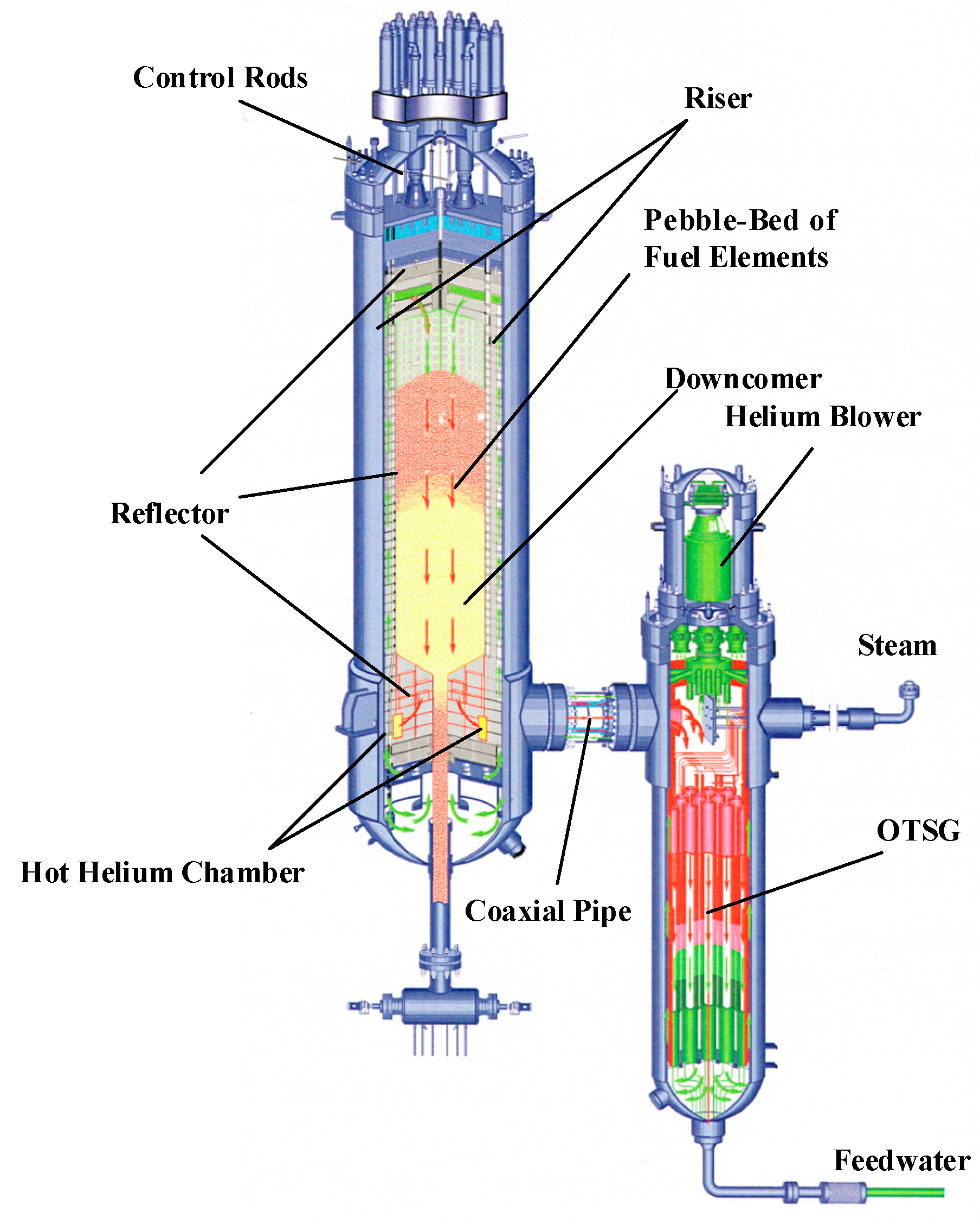
The improved DMC algorithm is implemented in a ten-module HTGR system. Previously, Dong et al. established a six-module HTGR simulation model based on MATLAB/Simulink 2023b [32]. Due to the modular design, the modeling principles and control system design for a ten-module HTGR are similar. The parameters of the system are provided in Table 1. The controlled object in this study is the cold helium temperature in a modular High-Temperature Gas-Cooled Reactor. Figure 2 shows a schematic diagram of the HTGR module, which primarily consists of a pebble-bed reactor core, a coaxial pipe, and helically coiled once-through steam generator arranged in parallel. The HTGR module uses a coaxial annular pipe to connect the reactor and the steam generator. The heated helium gas from the reactor core flows through the inner pipe into the primary side of the steam generator, where it transfers heat. Afterward, the cooled helium returns through the outer pipe to the reactor core and passes through an upward flow channel at the top of the core. Consequently, improper cold helium temperature may lead to structural material wear, affect the lifetime of instruments at the top of the reactor core, and ultimately degrade the operational reliability of the nuclear power plant. In addition, the cold helium temperature is an indicator of the thermal balance between the primary and secondary loops. Therefore, precise control of the cold helium temperature is essential to ensure the safe and efficient operation of the mHTGR system.
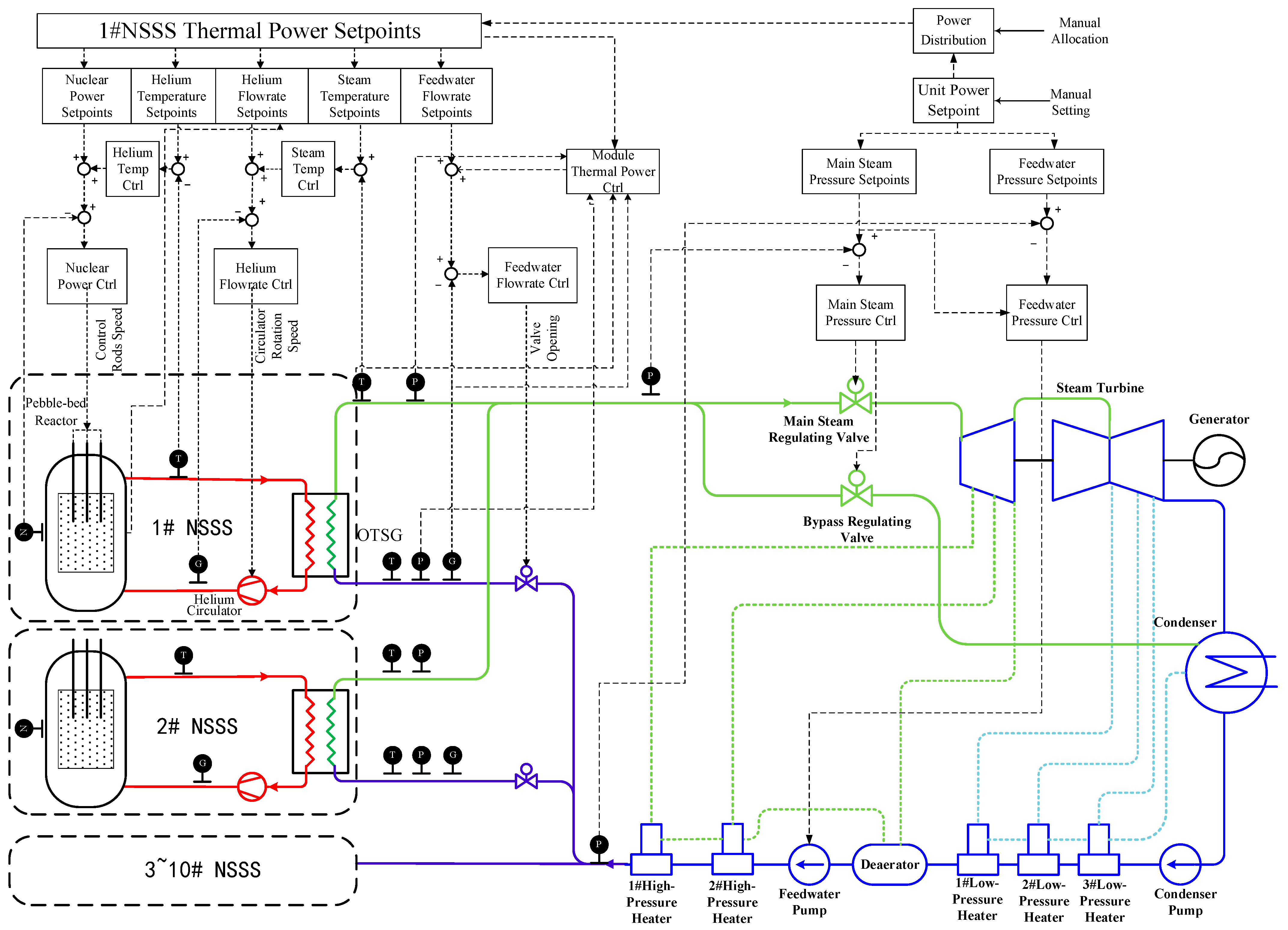
The current coordinated control system of mHTGR includes seven controllers: helium flow rate controller, feedwater flow rate controller, nuclear power controller, hot helium temperature controller, output thermal power controller, steam temperature controller, and main steam pressure controller, all working together to ensure the stability of the coordinated control system [33,34]. All controllers adopt a PID control structure. The architecture of the control system is shown in Figure 3. Therefore, the existing control object is a stable closed-loop system composed of the reactor unit and its embedded PID-based coordinated control system. For cold helium temperature regulation, it can be achieved by adjusting the hot helium temperature setpoint, which effectively transforms the control problem into an optimization problem targeting the upper-level steady-state setpoints. The inner loop maintains stability through the existing PID-based coordinated control system, while the outer loop employs DMC to optimize transient responses of the cold helium temperature.
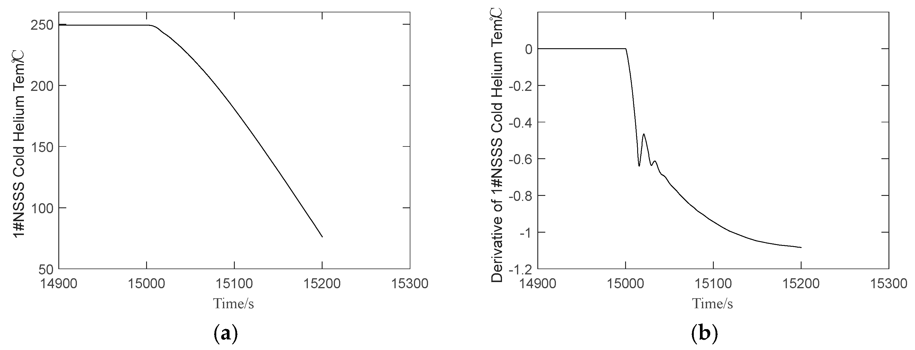
The predictive model of DMC is based on the step response data of the system. In this study, cold helium temperature control is achieved by adjusting the hot helium temperature setpoint. To establish the step response model, an open-loop step perturbation is applied to the hot helium temperature setpoint. However, the rolling horizon optimization inherent to DMC generates incremental setpoint adjustments at each sampling interval, which, if applied directly, would induce stepwise discontinuities in the controlled variable. To address this issue, an integrator is incorporated after the step response signal to regulate the rate of change in the hot helium temperature setpoint, thereby ensuring a smooth control trajectory. The specific implementation process is depicted in Figure 4. The step response curve of the cold helium temperature is shown in Figure 5.
The mHTGR coordinated control system will be augmented with a coordinated control service station (CCSS), serving as a dedicated platform for implementing advanced control algorithms. In practical operation, the DMC algorithm operates within the CCSS to dynamically optimize the hot helium temperature setpoint, which is then cascaded to the Level 1 distributed control system (DCS) without modifying the existing PID parameters of the coordinated control system. The control architecture is illustrated in Figure 6.

4.2. Simulation

During practical application, the step response coefficients may be affected by external noise or other physical quantities and cannot be accurately measured. In the cold helium temperature control system, the measurement noise primarily originates from the following aspects: (1) Sensor electronic noise: thermal noise from temperature sensors and amplifier noise, typically formed by superposition of numerous independent microscopic disturbances, conform to the central limit theorem and can be approximated as normal distributions. (2) Electromagnetic interference: strong electromagnetic fields in the reactor environment may introduce high-frequency noise, whose spectral characteristics are approximately uniform over a broad frequency band, exhibiting white noise features. (3) Hydrodynamic noise: pressure fluctuation-induced noise caused by helium flow demonstrates short-term correlation characteristics and can be approximated as white noise sequences after sampling.
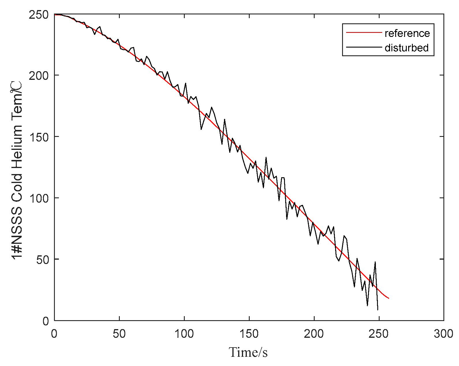
So, apply a normally distributed disturbance to the measured step response coefficients, as shown in Figure 7.
S u = S u r + Δ S ( k ) Δ S ( k ) = N ( 0 , α k )
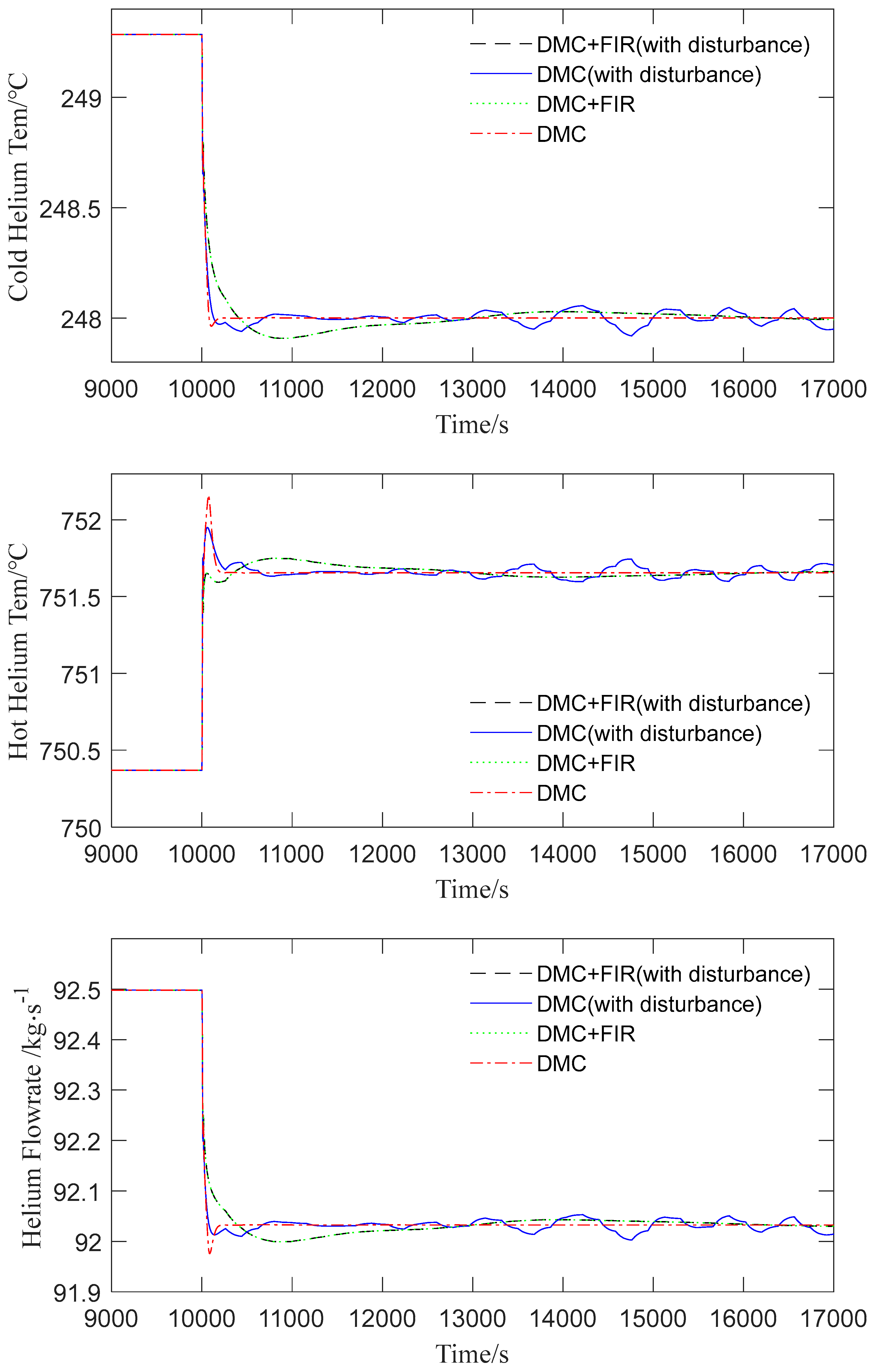
A −1 °C step change is applied to the cold helium temperature setpoint of the 1# NSSS, and the simulation results are shown in Figure 8. The control performance was primarily compared under four scenarios:
(1)
Step response coefficients unaffected by measurement noise, employing the conventional DMC method;
(2)
Step response coefficients unaffected by measurement noise, using the improved DMC method;
(3)
Step response coefficients affected by measurement noise, employing the conventional DMC method;
(4)
Step response coefficients affected by measurement noise, using the improved DMC method.
Detailed control performance metrics are presented in Table 2, where Δ , t s , and e ss represent the maximum deviation, settling time, and steady-state deviation, respectively.
When the step response coefficients are affected by white noise, the impact of FIR filters with different orders on the control performance is shown in Figure 9, and specific control performance metrics are summarized in Table 3. Here, the “computation count” refers to the number of filtering operations defined by Equation (32), reflecting the increased computational complexity.

4.3. Discussions

The existing mHTGR coordinated control system adjusts the nuclear power setpoint based on the deviation between the measured and set values of the hot helium temperature, thereby controlling the hot helium temperature through nuclear power regulation. The setpoint for the helium flow rate is corrected based on the deviation of the OTSG outlet steam temperature, and the steam temperature is controlled by adjusting the helium flow rate. In the actual control process, when the cold helium temperature setpoint decreases, the hot helium temperature setpoint increases in order to maintain the cold helium temperature at the desired value. To raise the hot helium temperature, nuclear power must be increased, thereby increasing the thermal power output and the steam temperature at the OTSG outlet. However, the reactor system requires the steam temperature at the OTSG outlet to remain stable. In order to reduce the outlet steam temperature, the helium flow rate must be decreased. As the hot helium temperature increases and the helium flow rate decreases, the cold helium temperature decreases to maintain stable thermal power output. Therefore, the DMC method can control the cold helium temperature by adjusting the hot helium temperature setpoint. Since this method essentially optimizes the upper-level steady-state setpoints, it does not affect the stability of the underlying coordinated PID control.
As observed in Figure 8, when the measured step response coefficient is accurate, the conventional DMC method can effectively regulate the cold helium temperature. However, when the measured step response coefficient is affected by noise and becomes inaccurate, oscillations in cold helium temperature control occur. In this case, by introducing a FIR filter to preprocess the measured step response coefficient, the oscillation of the cold helium temperature is effectively eliminated, thus improving the robustness of the algorithm. However, it should be noted that the introduction of the FIR filter leads to an extended settling time for the cold helium temperature. Therefore, the improvement in algorithm robustness comes at the cost of a certain reduction in control performance. The FIR filter is chosen because it is inherently stable, does not affect the overall system stability, and is easy to implement.
As illustrated in Figure 9 and Table 3, when the measurement of step response coefficients is affected by noise, higher-order FIR filters reduce the maximum deviation of cryogenic helium temperature, shorten the settling time, and enhance algorithmic robustness. These observations align with the conclusions derived from Equation (30). When the filter order is ≤10, the oscillation amplitude of the cold helium temperature exceeds acceptable limits, failing to meet system stability requirements. For filter orders > 20, the overshoot, however, remains nearly unchanged, and the reduction in settling time becomes marginal, indicating diminishing returns from further increasing the filter order. As shown in Equation (32), higher filter orders significantly increase computational load. Balancing computational complexity and real-time performance, the filter order should not exceed 20. Beyond this threshold, control performance improvements saturate, while computational demands continue to grow linearly. Therefore, a filter order of 20 is selected in this work.
In resource-constrained industrial controllers (e.g., STM32F407 with a 168 MHz clock frequency), hardware acceleration (e.g., DSP instruction sets) reduces the single-step computation time to 2.1 μs (0.0001% of the 2 s sampling period) for a 20th-order filter. Memory usage is only 20 × 4 Bytes (32-bit floating-point storage), far below the typical controller memory capacity (>1 MB).

5. Conclusions

This study enhances the robustness of conventional DMC algorithms by preprocessing measured dynamic step responses with a finite impulse response (FIR) filter. Sufficient conditions for the stability of the designed control algorithm are theoretically derived from a mechanistic perspective. The proposed control strategy is applied to cold helium temperature control in a mHTGR, employing a cascade control architecture where the inner loop maintains stability through an existing coordinated control system, while the outer loop utilizes the improved DMC to regulate the rate of change in hot helium temperature setpoints for effective cold helium temperature control. Numerical simulations demonstrate that this approach significantly improves the cold helium temperature response and exhibits strong robustness. Even when the measured step response coefficients are corrupted by noise, the method achieves satisfactory control performance, validating its practicality in noisy operational environments.

Author Contributions

Conceptualization, Z.W. and Z.D.; methodology, Z.W. and Z.D.; software, Z.W.; validation, Z.W., Z.D., and J.Z.; formal analysis, Z.W.; investigation, Z.W.; resources, Z.D. and J.Z.; data curation, Z.W.; writing—original draft preparation, Z.W.; writing—review and editing, Z.D.; visualization, Z.W.; supervision, Z.D. and J.Z.; project administration, Z.D.; funding acquisition, Z.D. All authors have read and agreed to the published version of the manuscript.

Funding

This work is jointly supported by the National Natural Science Foundation of China (NSFC) (Grant No. 62173202) and the National S&T Major Project (Grant No. ZX069).

Data Availability Statement

The data presented in this study are available on request from the corresponding author. (The data are not publicly available due to privacy restrictions).

Conflicts of Interest

Author Jilan Zhang was employed by the Huaneng Nuclear Energy Technology Research Institute. The remaining authors declare that the research was conducted in the absence of any commercial or financial relationships that could be construed as a potential conflict of interest. The funders had no role in the design of the study; in the collection, analyses, or interpretation of data; in the writing of the manuscript; or in the decision to publish the results.

References

  1. Cutler, C.R.; Ramaker, B.L. Dynamic Matrix controlA Computer Control Algorithm. In Proceedings of the 1980 Joint Automatic Control Conference, San Francisco, CA, USA, 13–15 August 1980. [Google Scholar]
  2. Richalet, J.; Rault, A.; Testud, J.; Papon, J. Model Predictive Heuristic Control—Applications to Industrial Process. Automatica 1978, 14, 413–428. [Google Scholar] [CrossRef]
  3. Garcia, C.; Prett, D.; Morari, M. Model Predictive Control—Theory and Practice—Survy. Automatica 1989, 25, 335–348. [Google Scholar] [CrossRef]
  4. Qin, S.J.; Badgwell, T.A. A Survey of Industrial Model Predictive Control Technology. Control Eng. Pract. 2003, 11, 733–764. [Google Scholar] [CrossRef]
  5. Nikravesh, M.; Farell, A.E.; Lee, C.T.; Van Zee, J.W. Dynamic Matrix Control of Diaphragm-Type Chlorine/Caustic Electrolysers. J. Process Control 1995, 5, 131–136. [Google Scholar] [CrossRef]
  6. Moon, U.-C.; Lee, Y.; Lee, K.Y. Practical Dynamic Matrix Control for Thermal Power Plant Coordinated Control. Control Eng. Pract. 2018, 71, 154–163. [Google Scholar] [CrossRef]
  7. Na, M.G.; Belle, X.X.; Upadhyaya, R.; Hwang, I.J. Design of a Model Predictive Power Controller for an SP-100 Space Reactor. Nucl. Sci. Eng. 2006, 154, 353–366. [Google Scholar] [CrossRef]
  8. Townsend, S.; Lightbody, G.; Brown, M.D.; Irwin, G.W. Nonlinear Dynamic Matrix Control Using Local Models. Trans. Inst. Meas. Control 1998, 20, 47–56. [Google Scholar] [CrossRef]
  9. Zhao, Z.; Xia, X.; Wang, J.; Gu, J.; Jin, Y. Nonlinear Dynamic Matrix Control Based on Multiple Operating Models. J. Process Control 2003, 13, 41–56. [Google Scholar] [CrossRef]
  10. Lee, J.; Morari, M.; Garcia, C. State-space interpretation of model-predictive control. Automatica 1994, 30, 707–717. [Google Scholar] [CrossRef]
  11. Jiang, D.; Dong, Z.; Liu, M.; Huang, X. Dynamic Matrix Control for the Thermal Power of MHTGR-Based Nuclear Steam Supply System. Energies 2018, 11, 2651. [Google Scholar] [CrossRef]
  12. Maiti, S.N.; Saraf, D.N. Adaptive Dynamic Matrix Control of a Distillation Column with Closed-Loop Online Identification. J. Process Control 1995, 5, 315–327. [Google Scholar] [CrossRef]
  13. Xu, X.; Simkoff, J.M.; Baldea, M.; Chiang, L.H.; Castillo, I.; Bindlish, R.; Ashcraft, B. Data-Driven Plant-Model Mismatch Estimation for Dynamic Matrix Control Systems. Int. J. Robust Nonlinear Control 2020, 30, 7103–7129. [Google Scholar] [CrossRef]
  14. Ding, Z.; Yang, Z.; Chen, C.; Chen, W.; Chen, H.; Liu, Z. Improved Sliding Mode Dynamic Matrix Control Strategy: Application on Spindle Loading and Precision Measuring Device Based on Piezoelectric Actuator. Mech. Syst. Signal Process. 2022, 167, 108543. [Google Scholar] [CrossRef]
  15. Na, M.G.; Hwang, I.J.; Lee, Y.J. Design of a Fuzzy Model Predictive Power Controller for Pressurized Water Reactors. IEEE Trans. Nucl. Sci. 2006, 53, 1504–1514. [Google Scholar]
  16. Chi, X.; Zhao, S.; Jia, X.; Hou, P. Fuzzy Dynamic Matrix Predictive Control of Ammonia Injection Quantityin SCR Denitration Systems. In Proceedings of the 2020 39th Chinese Control Conference (CCC), Shenyang, China, 27–29 July 2020; pp. 2494–2499. [Google Scholar]
  17. Temeng, K.O.; Schnelle, P.D.; McAvoy, T.J. Model Predictive Control of an Industrial Packed Bed Reactor Using Neural Networks. J. Process Control 1995, 5, 19–27. [Google Scholar] [CrossRef]
  18. Wang, L.; Cai, Y.; Zan, X. Distributed Double-Layered Dynamic Matrix Control for Large-Scale System. Math. Probl. Eng. 2022, 2022, 4650342. [Google Scholar] [CrossRef]
  19. Wang, D.; Zou, H.; Tao, J. A New Design of Fractional-Order Dynamic Matrix Control with Proportional–Integral–Derivative-Type Structure. Meas. Control 2019, 52, 567–576. [Google Scholar] [CrossRef]
  20. Teng, Y.; Li, H.; Wu, F. Design of Distributed Fractional Order PID Type Dynamic Matrix Controller for Large-Scale Process Systems. IEEE Access 2020, 8, 179754–179771. [Google Scholar] [CrossRef]
  21. Zou, H.; Wang, L. An Improved Constrained Dynamic Matrix Control for Temperature in an Industrial Coke Furnace. Meas. Control 2019, 52, 409–417. [Google Scholar] [CrossRef]
  22. Krener, A.J. Adaptive Horizon Model Predictive Regulation⁎. IFAC-Pap. 2018, 51, 54–59. [Google Scholar] [CrossRef]
  23. Jiang, D.; Dong, Z. Practical Dynamic Matrix Control of MHTGR-Based Nuclear Steam Supply Systems. Energy 2019, 185, 695–707. [Google Scholar] [CrossRef]
  24. Jiang, D.; Dong, Z. Dynamic Matrix Control for Thermal Power of Multi-Modular High Temperature Gas-Cooled Reactor Plants. Energy 2020, 198, 117386. [Google Scholar] [CrossRef]
  25. Ma, W.; Wang, S. Robustness of SISO Dynamic Matrix Control. J. Tsinghua Univ. Sci. Technol. 2002, 42, 1276–1280. [Google Scholar]
  26. Garcia, C.E.; Morari, M. Internal Model Control. A Unifying Review and Some New Results. Ind. Eng. Chem. Process Des. Dev. 1982, 21, 308–323. [Google Scholar] [CrossRef]
  27. Santos, T.L.M.; Normey-Rico, J.E. A Generalised Dynamic Matrix Control for Unstable Processes Based on Filtered Predictions. ISA Trans. 2023, 136, 297–307. [Google Scholar] [CrossRef]
  28. Xing, Y.; Zhang, G.; Yu, H.; Yang, J. Optimization and Simulation of Multivariable Dynamic Matrix Control. Comput. Eng. Sci. 2019, 41, 1285–1290. [Google Scholar]
  29. Tohidi, S.S.; Calì, D.; Madsen, H. Adaptive Model Predictive Controller for Building Thermal Dynamics. IEEE Control Syst. Lett. 2024, 8, 1325–1330. [Google Scholar] [CrossRef]
  30. Li, Z.; Wang, F.; Ke, D.; Li, J.; Zhang, W. Robust Continuous Model Predictive Speed and Current Control for PMSM With Adaptive Integral Sliding-Mode Approach. IEEE Trans. Power Electron. 2021, 36, 14398–14408. [Google Scholar] [CrossRef]
  31. Climente-Alarcon, V.; Antonino-Daviu, J.A.; Riera-Guasp, M.; Vlcek, M. Induction Motor Diagnosis by Advanced Notch FIR Filters and the Wigner–Ville Distribution. IEEE Trans. Ind. Electron. 2014, 61, 4217–4227. [Google Scholar] [CrossRef]
  32. Dong, Z.; Pan, Y.; Zhang, Z.; Dong, Y.; Huang, X. Dynamical Modeling and Simulation of the Six-Modular High Temperature Gas-Cooled Reactor Plant HTR-PM600. Energy 2018, 155, 971–991. [Google Scholar] [CrossRef]
  33. Dong, Z.; Pan, Y.; Huang, X.; Dong, Y.; Zhang, Z. Coordinated Control System Design and Verification of HTR-PM Plant. Nucl. Eng. Des. 2018, 329, 25–33. [Google Scholar] [CrossRef]
  34. Dong, Z.; Li, B.; Huang, X.; Dong, Y.; Zhang, Z. Power-Pressure Coordinated Control of Modular High Temperature Gas-Cooled Reactors. Energy 2022, 252, 124042. [Google Scholar] [CrossRef]
Figure 1. Schematic Diagram of Step Response for Integral-Type Systems.
Energies 18 02145 g001
Figure 2. Schematic view of a MHTGR-based NSSS module.
Energies 18 02145 g002
Figure 3. Ten-module High-Temperature Gas-Cooled Reactor (HTGR) coordinated control system.
Energies 18 02145 g003
Figure 4. Schematic diagram of step response testing.
Energies 18 02145 g004
Figure 5. The cold helium temperature response curve to a +1 °C step change in the hot helium temperature setpoint. (a) Cold helium temperature curve; (b) Cold helium temperature rate-of-change curve.
Energies 18 02145 g005
Figure 6. Schematic diagram of cold helium temperature control.
Energies 18 02145 g006
Figure 7. Cold helium temperature response under a +1 °C step change in the hot helium temperature rate with a normally distributed disturbance.
Energies 18 02145 g007
Figure 8. Responses of cold helium temperature, hot helium temperature, and helium flow rate under a −1 °C step change in the cold helium temperature setpoint of 1# NSSS.
Energies 18 02145 g008
Figure 9. Responses of cold helium temperature, hot helium temperature, and helium flow rate under a −1 °C step change in the cold helium temperature setpoint of 1# NSSS, with FIR filters of different orders.
Energies 18 02145 g009aEnergies 18 02145 g009b
Table 1. Steady state values of key parameters of high temperature gas cooled reactor unit.
ParametersUnitValue
Thermal powerMW253
Hot helium temperature°C750
Cold helium temperature°C250
Helium flowrateskg/s96.26
Steam pressureMPa24.2
Steam temperature°C571
Feedwater flowratekg/s95.6
Table 2. Control performance metrics of different methods with and without disturbance.
Cold Helium TemperatureHot Helium TemperatureHelium Flowrate
Δ /°C t s /s e ss /°C σ /°C t s /s e ss /°C Δ / kg s 1 t s /s e ss / kg s 1
DMC+FIR
(Robust case)
0.092200000.096200000.03320000
DMC
(Robust case)
0.061//0.290//0.023//
DMC+FIR
(Nominal case)
0.092200000.096200000.03320000
DMC
(Nominal case)
0.037185.500.50522800.0572280
Table 3. Control performance metrics under different FIR filter orders.
Cold Helium TemperatureHot Helium TemperatureHelium FlowrateComputation Count
Δ /°C t s /s e ss /°C Δ /°C t s /s e ss /°C Δ / kg s 1 t s /s e ss / kg s 1
50.190//0.193//0.069//900
100.118//0.120//0.053//1900
150.097224000.100210600.036215202900
200.089200000.094200000.033200003900
250.089154300.094166900.033156404900
300.089154300.094155500.033146505900
Disclaimer/Publisher’s Note: The statements, opinions and data contained in all publications are solely those of the individual author(s) and contributor(s) and not of MDPI and/or the editor(s). MDPI and/or the editor(s) disclaim responsibility for any injury to people or property resulting from any ideas, methods, instructions or products referred to in the content.