
Impact of Corrugated Fins on Flow and Heat Transfer Performance in Medium-Deep Coaxial Underground Heat Exchangers

Abstract
:1. Introduction
2. Working Principle and Evaluation Metrics of CUHEs
2.1. Working Principle
2.2. Evaluation Metrics
3. Numerical Model
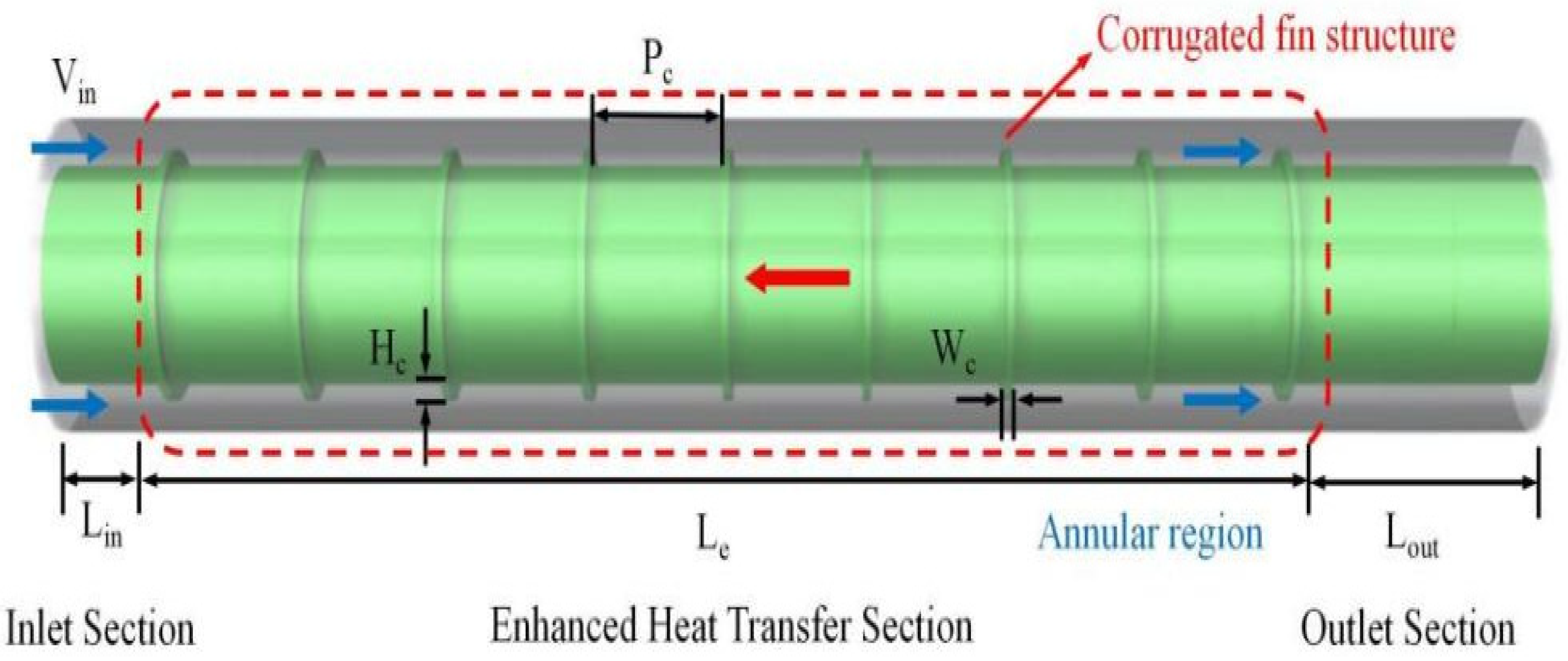
3.1. Physical Model
3.2. Boundary Conditions and Numerical Methods
- (1)
- Inlet: A velocity inlet boundary condition is specified, with inlet velocities set to correspond to the investigated Reynolds number range of 12,000 to 42,000. The fluid inlet temperature is set to 43 °C to represent typical operating temperatures in practical applications within the Songliao Basin, and to reflect the region’s geological and climatic characteristics.
- (2)
- Outlet: A pressure outlet boundary condition is applied at the outlet, with atmospheric pressure.
- (3)
- Walls: A constant heat flux of 600 W/m2 is applied to the outer tube wall to simulate heat transfer. The inner tube wall and corrugated fins are considered adiabatic. No-slip boundary conditions are imposed on all inner and outer tube walls and fin surfaces to accurately capture the fluid-solid interaction.
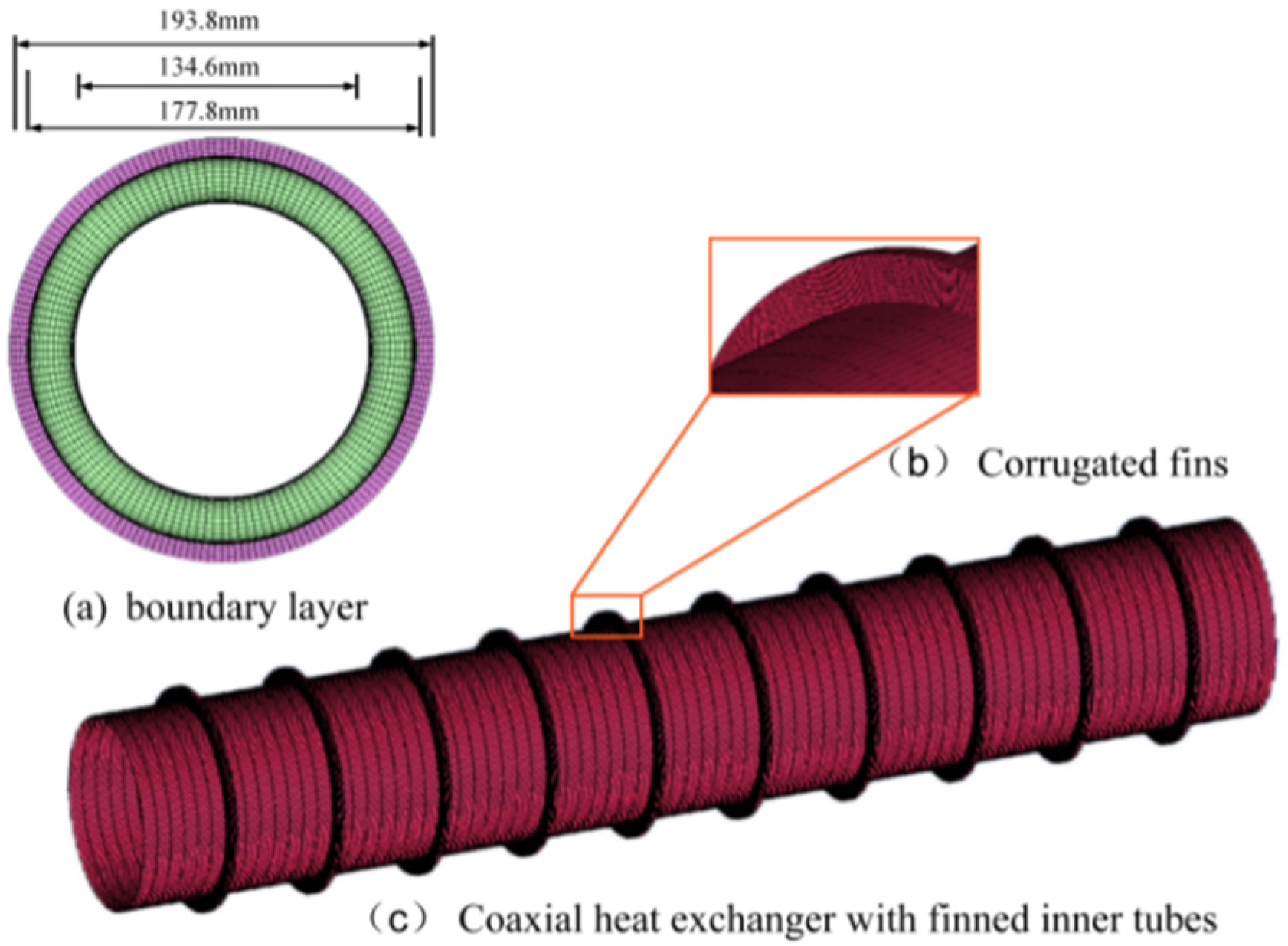
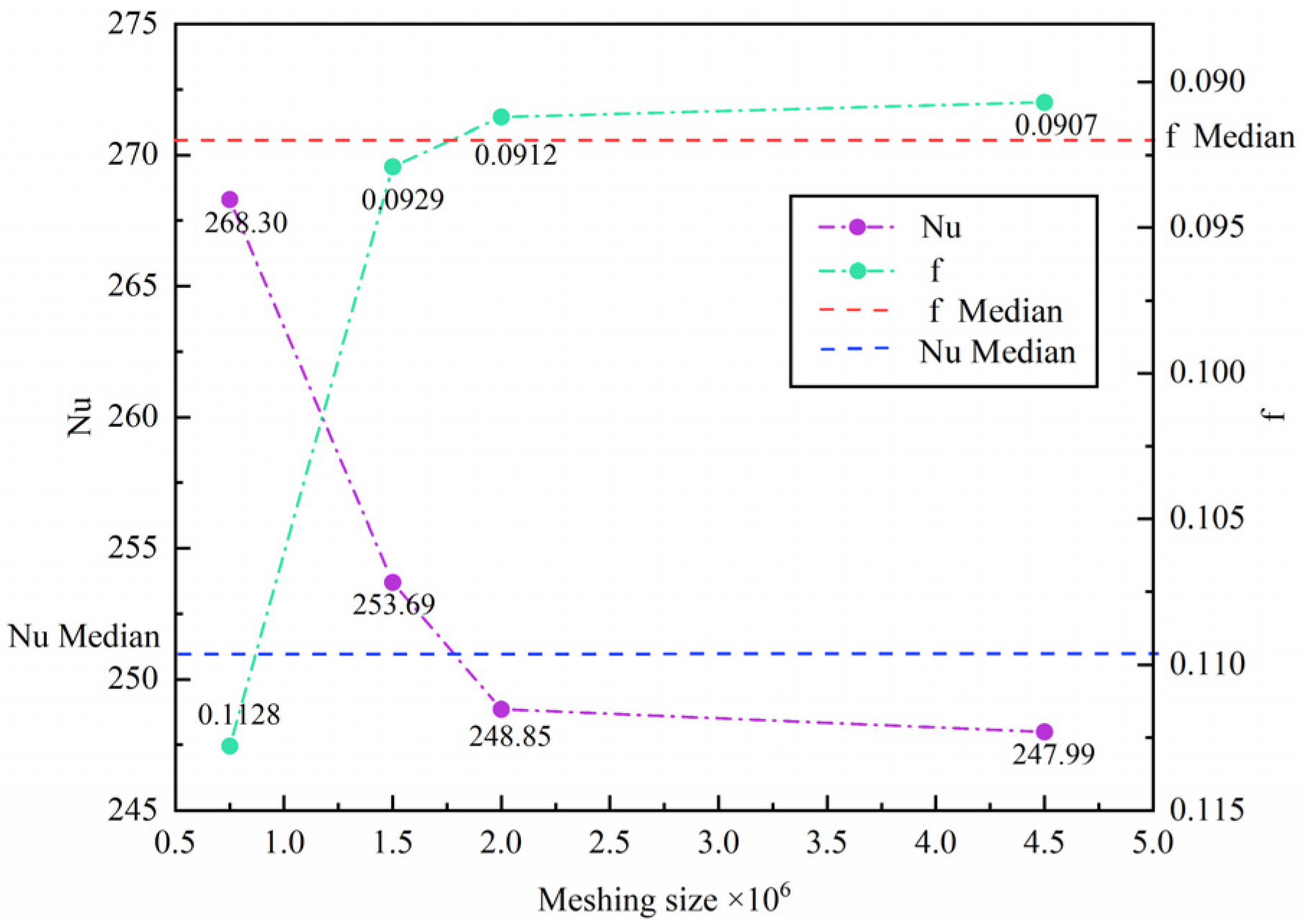
3.3. Mesh Generation and Mesh Independence Validation
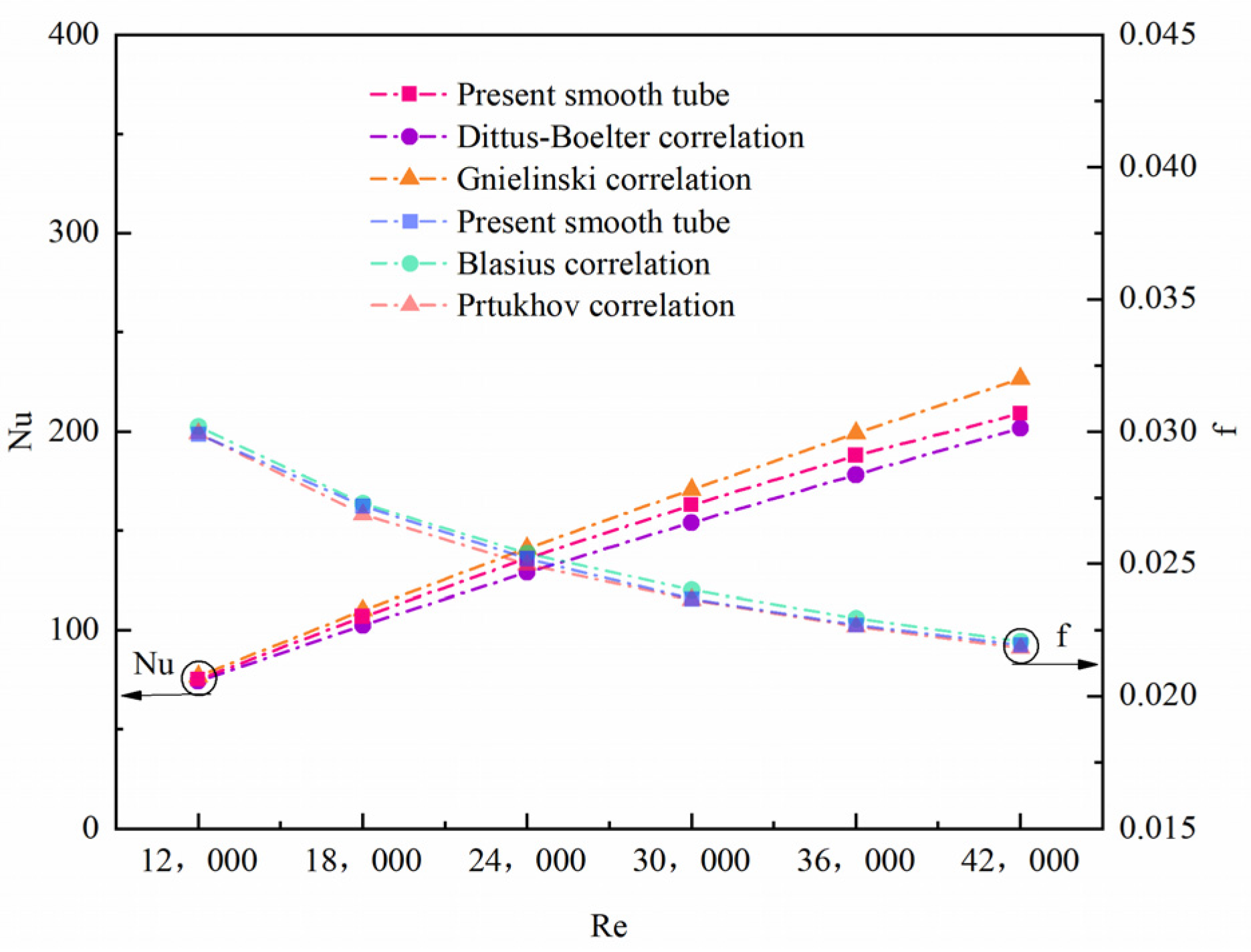
3.4. Model Validation
4. Results and Discussion
4.1. Mechanism of Augmented Heat Transfer
4.2. Influence of Corrugation Width
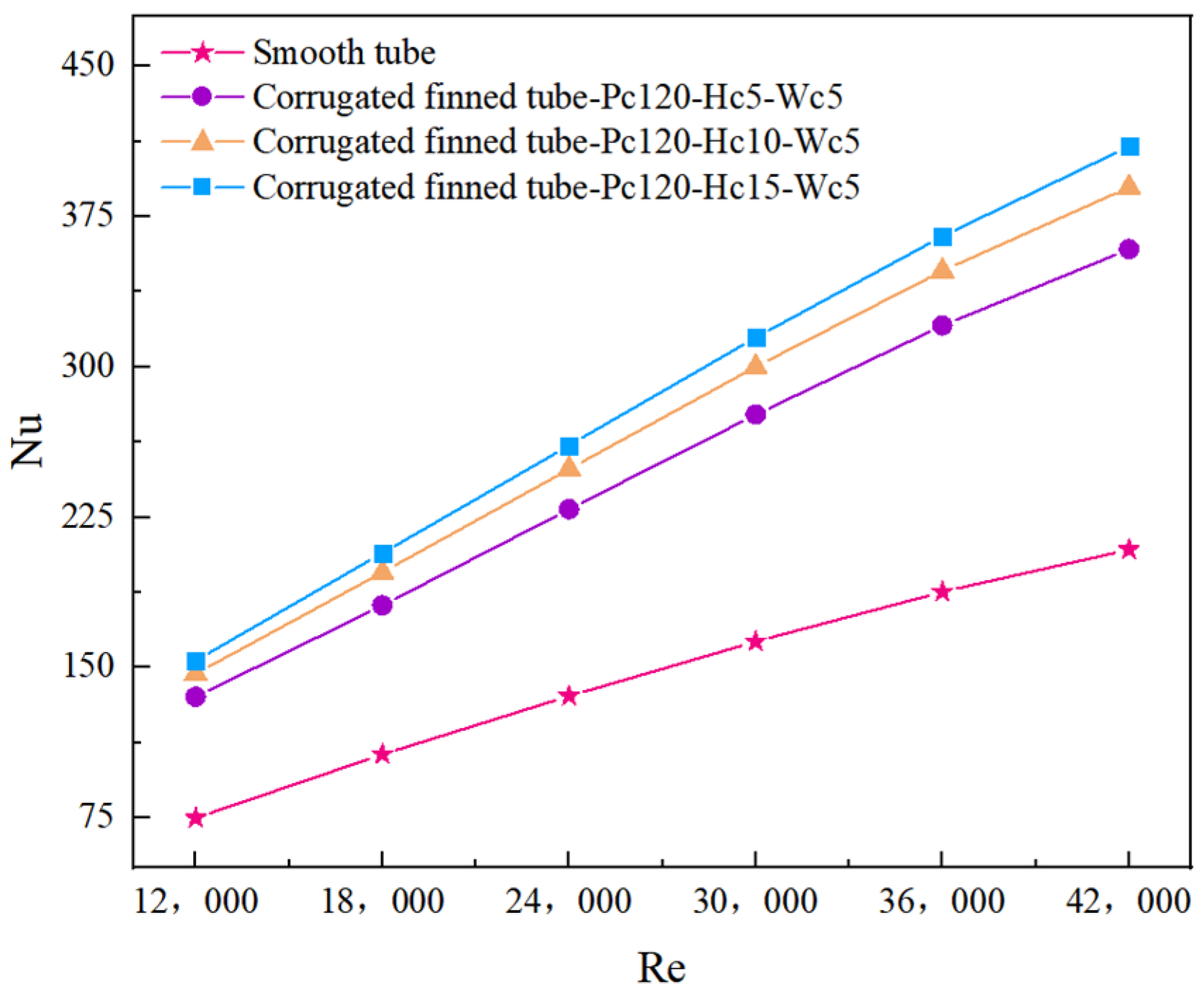
4.2.1. Effect of Different Hc on the Nusselt Number (Nu)
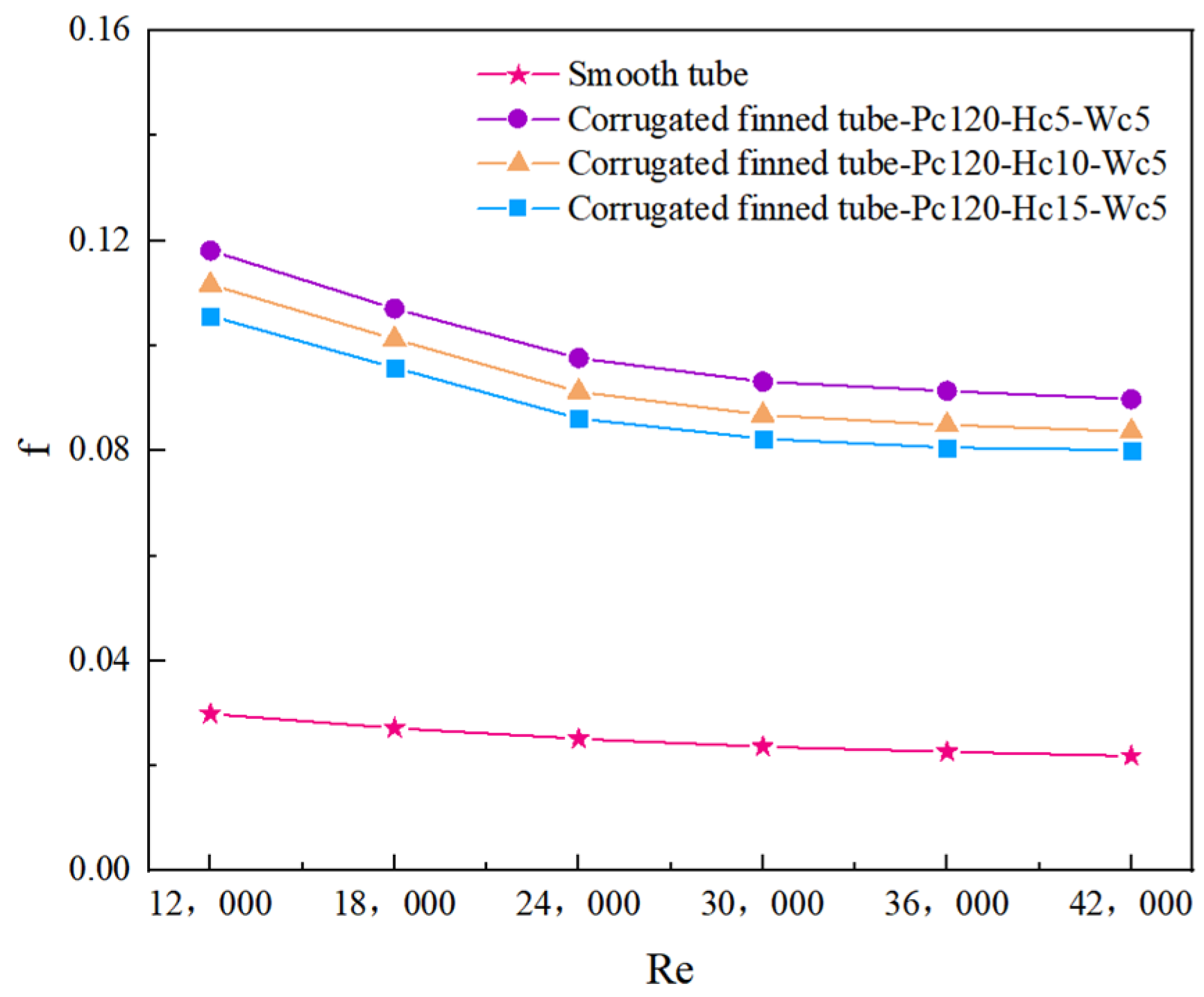
4.2.2. Effect of Different Hc on the Friction Coefficient (f)
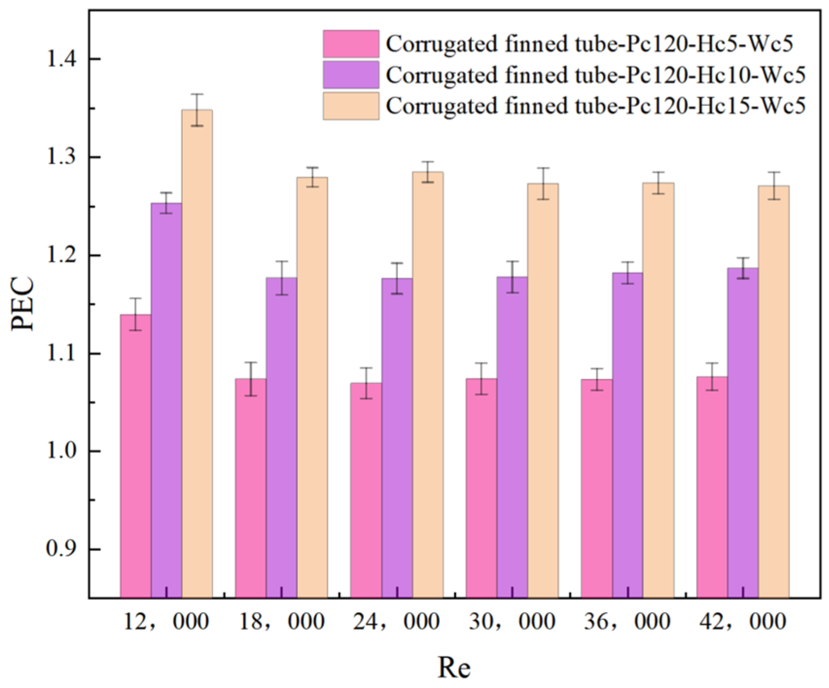
4.2.3. Effect of Different Hc on the Thermal Performance Coefficient (PEC)
4.3. Impact of Corrugation Pitch
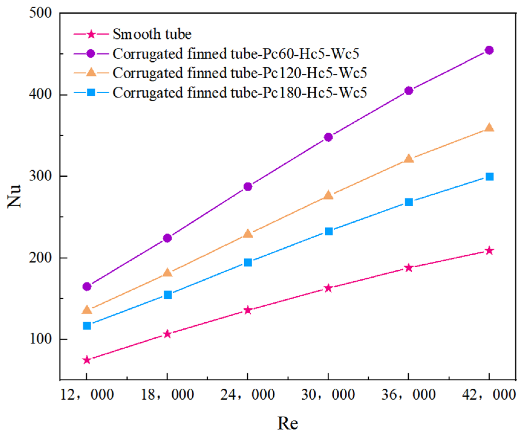
4.3.1. Effect of Different Pc on the Nusselt Number (Nu)
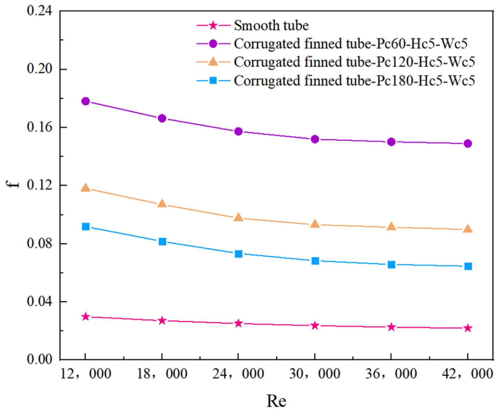
4.3.2. Effect of Different Pc on the Friction Coefficient (f)
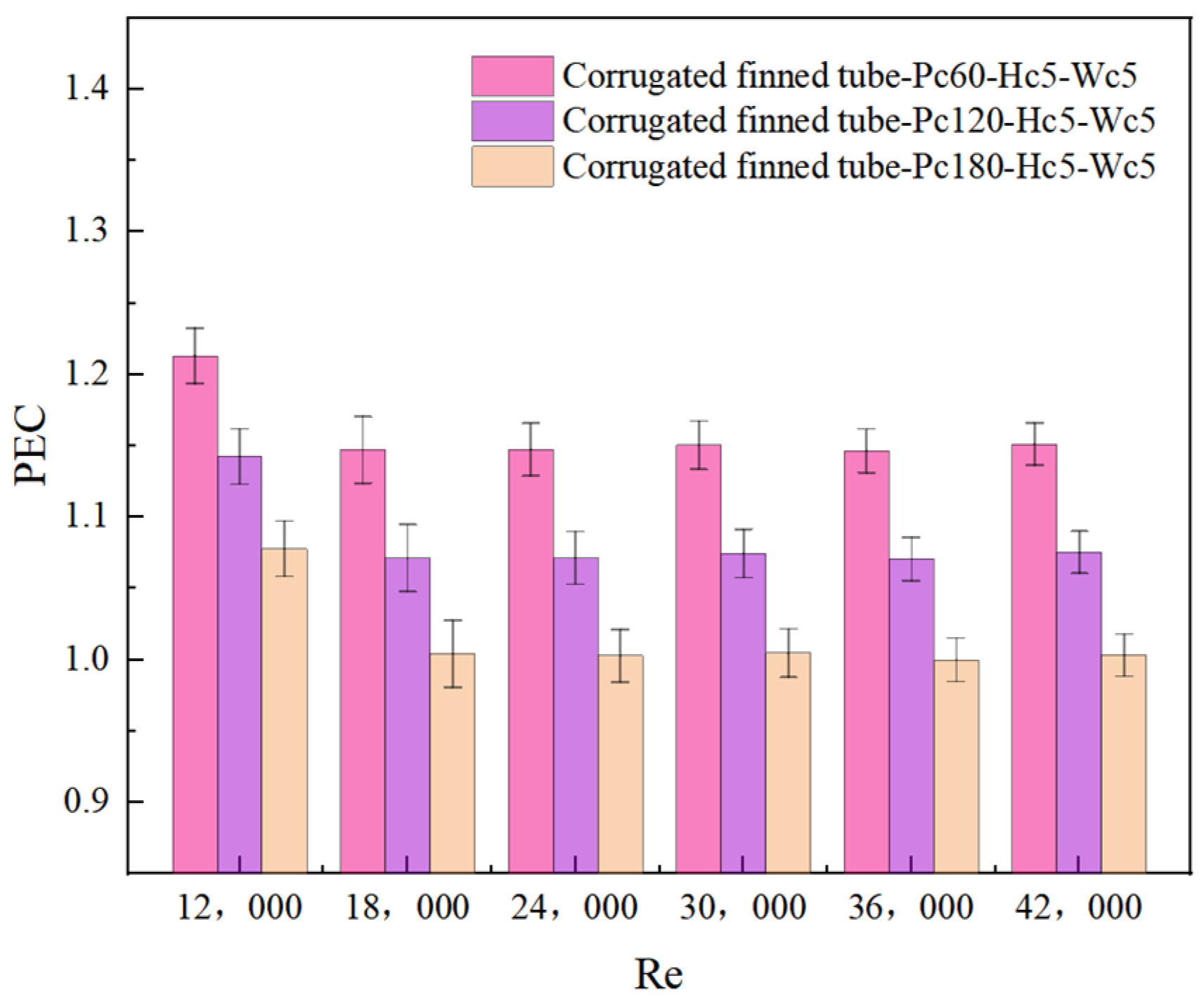
4.3.3. Effect of Different Pc on the Thermal Performance Coefficient (PEC)
5. Conclusions
- The Nu, f, and PEC serve as key parameters for evaluating heat exchanger performance. The results demonstrate that as the corrugation width (Hc) is increased, the f decreases, while both the Nu and PEC increase. Specifically, compared to the smooth inner tube configuration, the CUHEs exhibit Nu values 1.71–2.04 times, f values 3.53–4.09 times, and PEC values 1.07–1.34 times higher, respectively, than those of the smooth inner tube configuration. Consequently, increasing the corrugated fin width leads to a significant enhancement in the thermal performance of the CUHE.
- With increasing pitch of the corrugated fins, both Nu and f decrease, and the PEC also decreases. Specifically, compared to the smooth tube configuration, the Nu values for various pitches are 1.43–2.19 times, the f values are 2.94–6.79 times, and the PEC values are 1.00–1.15 times that of the smooth tube configuration. This suggests that reducing pitch is beneficial for performance improvement.
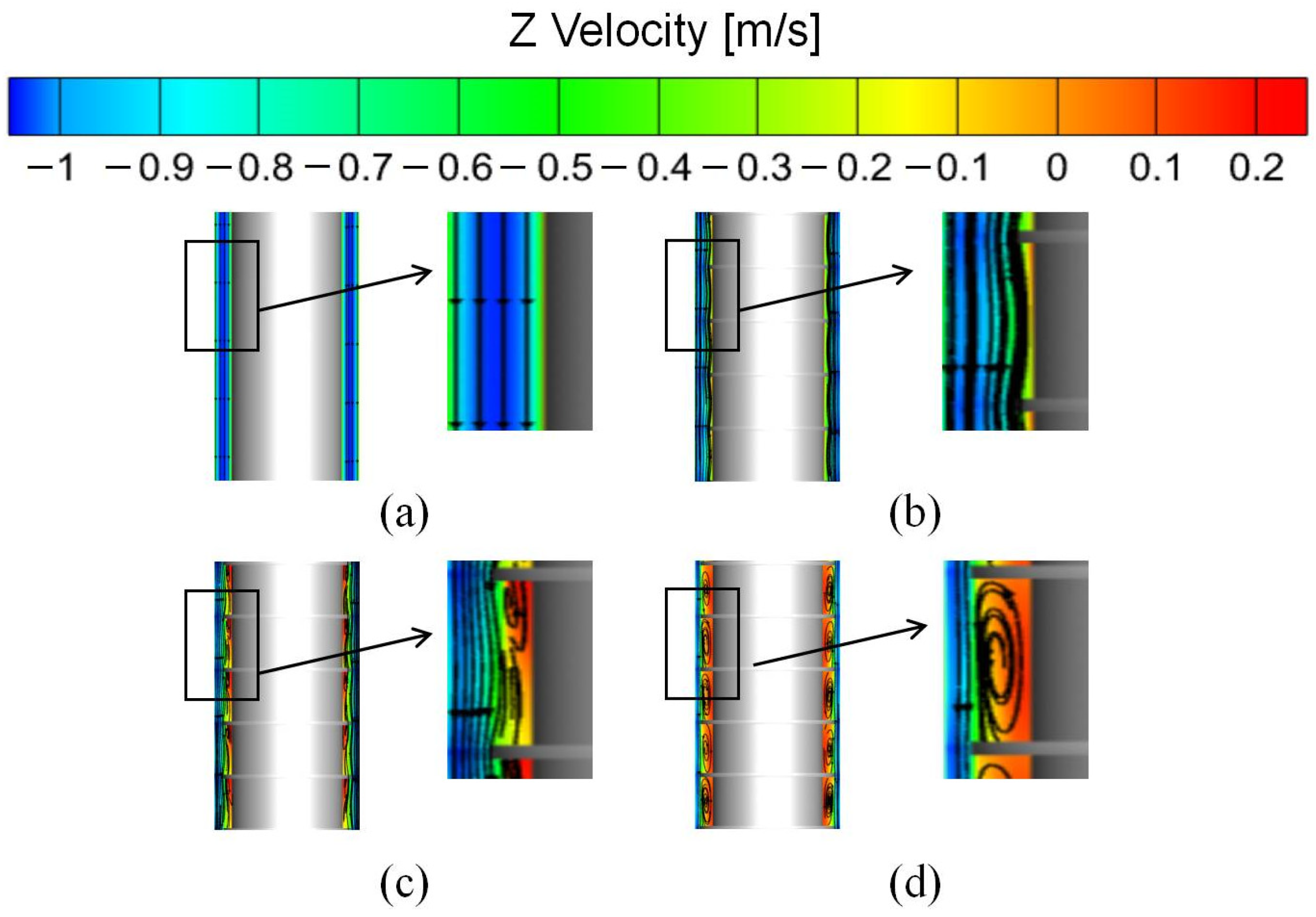
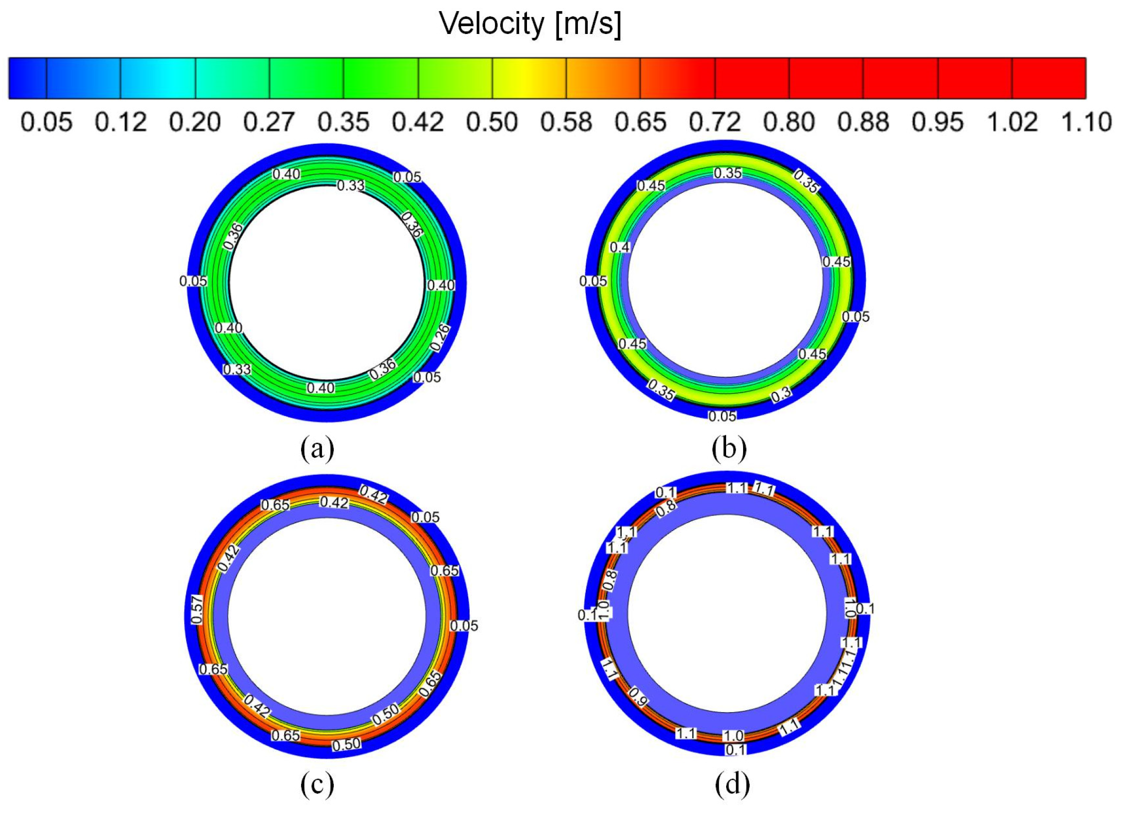
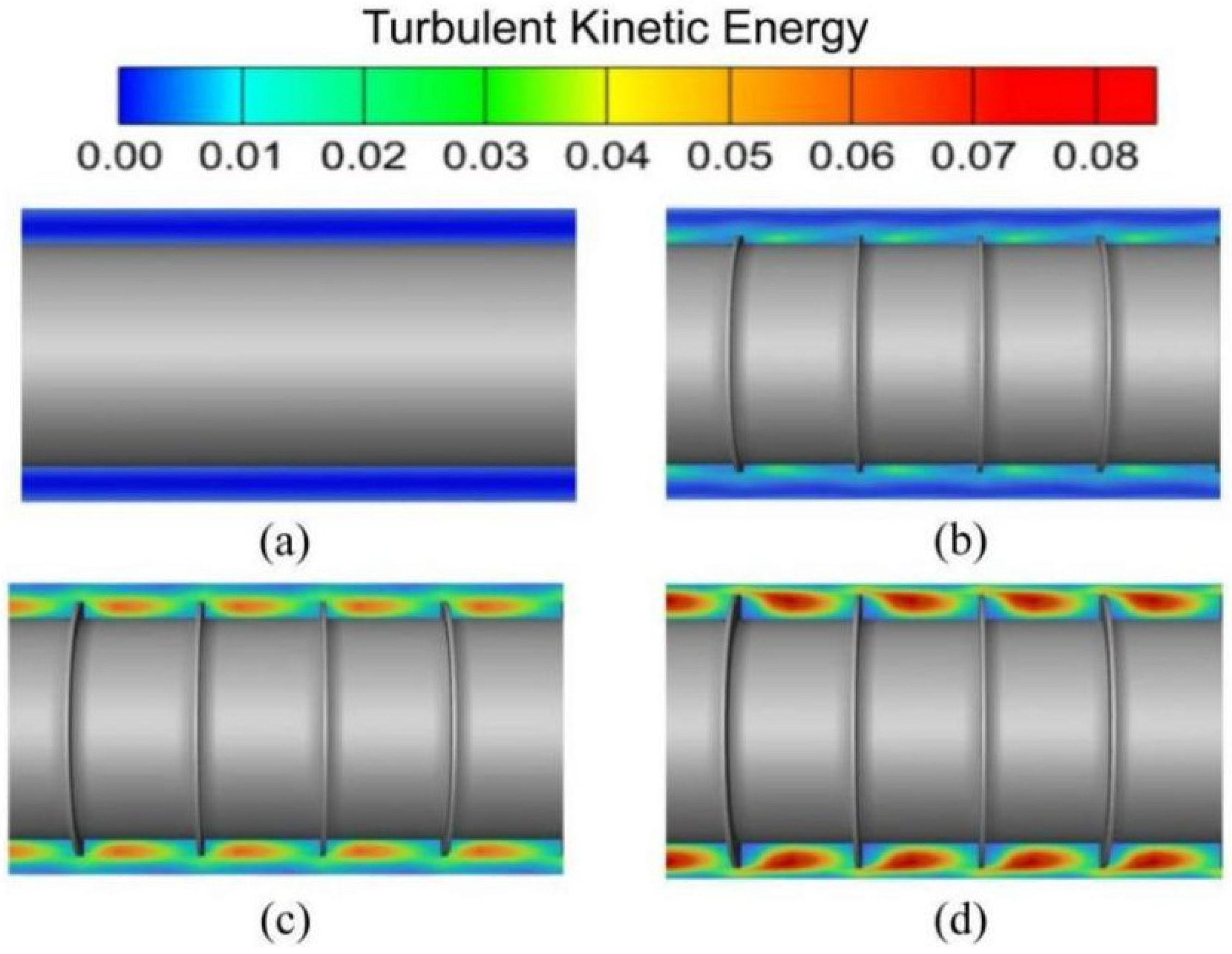
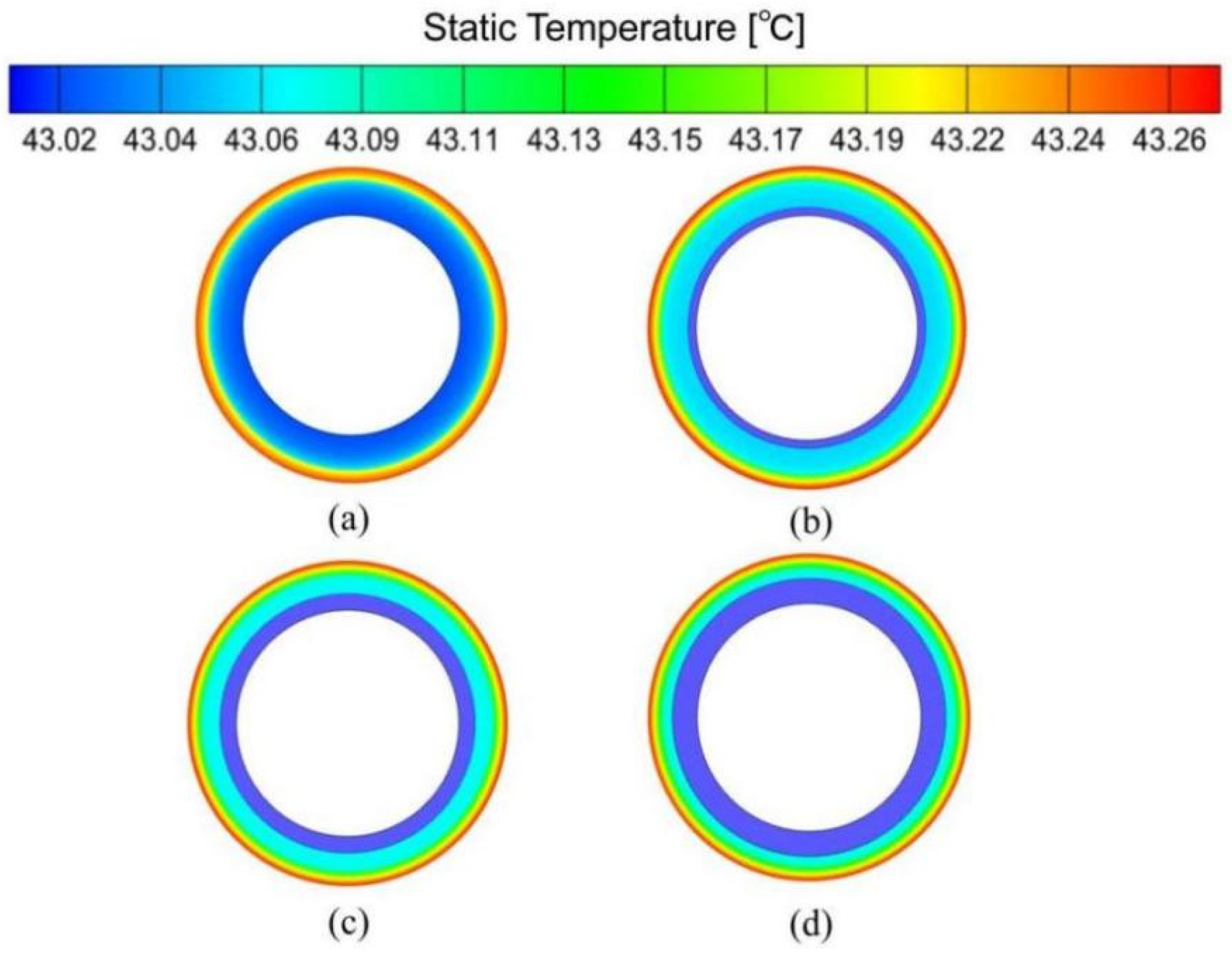
- At Re = 12,000, the CUHE with a width of 5 mm, a pitch of 60 mm, and a thickness of 15 mm exhibits excellent heat transfer enhancement performance. The corrugated fins effectively promote the full mixing of hot fluid in the near-wall region and cold fluid in the core region by enhancing fluid disturbance, increasing turbulence intensity, and forming vortices. This process accelerates the heat energy transfer rate and promotes heat exchange, ultimately resulting in enhanced heat transfer. Furthermore, compared to other fin geometries, this corrugated fin structure not only significantly improves heat transfer performance but also maintains the flow resistance within an acceptable range, thereby achieving optimal overall thermal performance.
Author Contributions
Funding
Data Availability Statement
Conflicts of Interest
References
- Wang, Y.; Li, S.; Gu, X.; Sun, Q.; Zhang, R.; Chen, F. Spatio-temporal evolution and multi-subject influencing factors of urban green development efficiency in China: Under the carbon neutral vision constraint. Ecol. Indic. 2024, 167, 112580. [Google Scholar] [CrossRef]
- Zhu, Y.; Wu, S.; Li, J.; Jia, Q.; Zhang, T.; Zhang, X.; Han, D.; Tan, Y. Towards a carbon-neutral community: Integrated renewable energy systems (IRES)–sources, storage, optimization, challenges, strategies and opportunities. J. Energy Storage 2024, 83, 110663. [Google Scholar] [CrossRef]
- Wang, K.; Yuan, B.; Ji, G.; Wu, X. A comprehensive review of geothermal energy extraction and utilization in oilfields. J. Pet. Sci. Eng. 2018, 168, 465–477. [Google Scholar] [CrossRef]
- Tao, J.; Zhang, Q.; Sun, H.; Xu, B.; Liu, C.-l.; Jiao, Z.-x. Summary of the 11th Chinese National Conference on Fluid Power Transmission and Control. Chin. Hydraul. Pneum. 2021, 45, 1–17. [Google Scholar]
- Huang, Y.; Zhang, Y.; Xie, Y.; Zhang, Y.; Gao, X.; Ma, J. Long-term thermal performance analysis of deep coaxial borehole heat exchanger based on field test. J. Clean. Prod. 2021, 278, 123396. [Google Scholar] [CrossRef]
- Uzelli, T.; Ayzit, T.; Baba, A. An Introduction to Geothermal Energy. In Encyclopedia of Renewable Energy, Sustainability and the Environment, 1st ed.; Rahimpour, M.R., Ed.; Elsevier: Oxford, UK, 2024; pp. 1–12. [Google Scholar]
- Matyska, C.; Zábranová, E. Seasonal energy extraction and storage by deep coaxial borehole heat exchangers in a layered ground. Renew. Energy 2024, 237, 121530. [Google Scholar] [CrossRef]
- Xie, J.; Miao, L. Research on multi-objective optimization of China’s energy consumption structure. Decis. Mak. 2023, 7, 159–167. [Google Scholar]
- Hu, Q.; Yuan, K.; Peng, W.; Zhao, G.; Wang, J. A numerical study of heat transfer enhancement by helically corrugated tubes in the intermediate heat exchanger of a very-high-temperature gas-cooled reactor. Nucl. Eng. Des. 2021, 380, 111275. [Google Scholar] [CrossRef]
- Bergles, A.E.; Manglik, R.M. Current progress and new developments in enhanced heat and mass transfer. J. Enhanc. Heat Transf. 2013, 20, 1–15. [Google Scholar] [CrossRef]
- Song, K.; Xi, Z.; Su, M.; Wang, L.; Wu, X.; Wang, L. Effect of geometric size of curved delta winglet vortex generators and tube pitch on heat transfer characteristics of fin-tube heat exchanger. Exp. Therm. Fluid Sci. 2017, 82, 8–18. [Google Scholar] [CrossRef]
- Tavousi, E.; Perera, N.; Flynn, D.; Hasan, R. Heat transfer and fluid flow characteristics of the passive method in double tube heat exchangers: A critical review. Int. J. Thermofluids 2023, 17, 100282. [Google Scholar] [CrossRef]
- Du, J.; Hong, Y. Numerical simulation on fluid flow and heat transfer characteristics in inward sinusoidal rib enhanced tube heat exchangers for waste heat recovery: Comparisons and parametric studies. Int. J. Therm. Sci. 2021, 167, 107030. [Google Scholar] [CrossRef]
- Arasteh, H.; Rahbari, A.; Mashayekhi, R.; Keshmiri, A.; Mahani, R.B.; Talebizadehsardari, P. Effect of pitch distance of rotational twisted tape on the heat transfer and fluid flow characteristics. Int. J. Therm. Sci. 2021, 170, 106966. [Google Scholar] [CrossRef]
- Mohammed, H.A.; Abbas, A.K.; Sheriff, J.M. Influence of geometrical parameters and forced convective heat transfer in transversely corrugated circular tubes. Int. Commun. Heat Mass Transf. 2013, 44, 116–126. [Google Scholar] [CrossRef]
- Tepe, A.Ü. Heat transfer enhancement of fin-tube heat exchangers using punched triangular ramp vortex generator on the fin surface. Int. J. Heat Mass Transf. 2021, 174, 121326. [Google Scholar] [CrossRef]
- Hashemian, M.; Jafarmadar, S.; Nasiri, J.; Sadighi Dizaji, H. Enhancement of heat transfer rate with structural modification of double pipe heat exchanger by changing cylindrical form of tubes into conical form. Appl. Therm. Eng. 2017, 118, 408–417. [Google Scholar] [CrossRef]
- Liaw, K.L.; Kurnia, J.C.; Sasmito, A.P. Turbulent convective heat transfer in helical tube with twisted tape insert. Int. J. Heat Mass Transf. 2021, 169, 120918. [Google Scholar] [CrossRef]
- Jalili, P.; Kazerani, K.; Jalili, B.; Ganji, D.D. Investigation of thermal analysis and pressure drop in non-continuous helical baffle with different helix angles and hybrid nano-particles. Case Stud. Therm. Eng. 2022, 36, 102209. [Google Scholar] [CrossRef]
- Bhattacharyya, S.; Chattopadhyay, H.; Benim, A.C. Simulation of heat transfer enhancement in tube flow with twisted tape insert. Prog. Comput. Fluid Dyn. 2017, 17, 193. [Google Scholar] [CrossRef]
- Han, H.-Z.; Li, B.-X.; Yu, B.-Y.; He, Y.-R.; Li, F.-C. Numerical study of flow and heat transfer characteristics in outward convex corrugated tubes. Int. J. Heat Mass Transfer. 2012, 55, 7782–7802. [Google Scholar] [CrossRef]
- Mohsen, O.A.; Muhammed, M.A.R.; Hasan, B.O. Heat Transfer Enhancement in a Double Pipe Heat Exchanger Using Different Fin Geometries in Turbulent Flow. Iran. J. Sci. Technol. Trans. Mech. Eng. 2021, 45, 461–471. [Google Scholar] [CrossRef]
- Syed, K.S.; Ishaq, M.; Iqbal, Z.; Hassan, A. Numerical study of an innovative design of a finned double-pipe heat exchanger with variable fin-tip thickness. Energy Convers. Manag. 2015, 98, 69–80. [Google Scholar] [CrossRef]
- Kumar, M.S.; Abraham, S. Experimental and numerical studies of detailed heat transfer and flow characteristics in the rib turbulated annulus of a double pipe heat exchanger. Int. J. Therm. Sci. 2025, 207, 109382. [Google Scholar] [CrossRef]
- Rajeh, T.; Al-Kbodi, B.H.; Yang, L.; Zhao, J.; Zayed, M.E. A novel oval-shaped coaxial ground heat exchanger for augmenting the performance of ground-coupled heat pumps: Transient heat transfer performance and multi-parameter optimization. J. Build. Eng. 2023, 79, 107781. [Google Scholar] [CrossRef]
- Rajeh, T.; Al-Kbodi, B.H.; Zayed, M.E.; Li, Y.; Zhao, J.; Rehman, S. Local entropy generation optimization and thermodynamic irreversibility analysis of oval-shaped coaxial ground heat exchangers: A detailed numerical investigation. Int. J. Heat Mass Transfer. 2024, 228, 125650. [Google Scholar] [CrossRef]
- Kanaris, A.G.; Mouza, A.A.; Paras, S.V. Flow and Heat Transfer in Narrow Channels with Corrugated Walls: A CFD Code Application. Chem. Eng. Res. Des. 2005, 83, 460–468. [Google Scholar] [CrossRef]
- Dizaji, H.S.; Jafarmadar, S.; Mobadersani, F. Experimental studies on heat transfer and pressure drop characteristics for new arrangements of corrugated tubes in a double pipe heat exchanger. Int. J. Therm. Sci. 2015, 96, 211–220. [Google Scholar] [CrossRef]
- Bashtani, I.; Esfahani, J.A. ε-NTU analysis of turbulent flow in a corrugated double pipe heat exchanger: A numerical investigation. Appl. Therm. Eng. 2019, 159, 113886. [Google Scholar] [CrossRef]
- Darzi, A.A.R.; Farhadi, M.; Sedighi, K.; Shafaghat, R.; Zabihi, K. Experimental investigation of turbulent heat transfer and flow characteristics of SiO2/water nanofluid within helically corrugated tubes. Int. Commun. Heat Mass Transf. 2012, 39, 1425–1434. [Google Scholar] [CrossRef]
- Fernández-Seara, J.; Uhía, F.J. Heat transfer and friction characteristics of spirally corrugated tubes for outer ammonia condensation. Int. J. Refrig. 2012, 35, 2022–2032. [Google Scholar] [CrossRef]
- Pethkool, S.; Eiamsa-ard, S.; Kwankaomeng, S.; Promvonge, P. Turbulent heat transfer enhancement in a heat exchanger using helically corrugated tube. Int. Commun. Heat Mass Transf. 2011, 38, 340–347. [Google Scholar] [CrossRef]
- Al-Obaidi, A.R.; Alhamid, J.; Khalaf, H.A. Effect of different corrugation interruptions Parameters on thermohydrodynamic characteristics and heat transfer performance of 3D Three-dimensional corrugated tube. Case Stud. Therm. Eng. 2022, 32, 101879. [Google Scholar] [CrossRef]
- Liu, Q.; Zhang, Y.; Zhang, X.; Luo, J.; Zheng, J.; Liu, Y.; Cheng, Y.; Lou, J. Numerical study on the heat transfer performance evaluation, flow characteristics, exergy efficiency, and entropy generation analysis of a novel coaxial geothermal heat exchanger. J. Build. Eng. 2024, 84, 108555. [Google Scholar] [CrossRef]
- Gong, Q.; Yu, C.; Wang, W.; Wang, Y. Experimental and numerical exploration on improved heat transfer by continuous spiral flow in shell of spiral wound corrugated tube heat exchanger. Case Stud. Therm. Eng. 2023, 51, 103483. [Google Scholar] [CrossRef]
- Hasan, N.; Ali, M.H.; Pratik, N.A.; Lubaba, N.; Miyara, A. Improving the thermal performance of vertical ground heat exchanger by modifying spiral tube geometry: A numerical study. Heliyon 2024, 10, e35718. [Google Scholar] [CrossRef]
- Zhang, B.; Chu, W.; Wang, Q. Analysis on heat transfer enhancement mechanism in a cross-wavy primary surface heat exchanger based on advection thermal resistance method. Int. J. Heat Fluid Flow 2024, 109, 109556. [Google Scholar] [CrossRef]
- Shih, T.-H.; Liou, W.W.; Shabbir, A.; Yang, Z.; Zhu, J. A new k-ϵ eddy viscosity model for high reynolds number turbulent flows. Comput. Fluids 1995, 24, 227–238. [Google Scholar] [CrossRef]
- Dittus, F.W.; Boelter, L.M.K. Heat transfer in automobile radiators of the tubular type. Int. Commun. Heat Mass Transf. 1985, 12, 3–22. [Google Scholar] [CrossRef]
- Gnielinski, V. New equations for heat and mass transfer in turbulent pipe and channel flow. J. Int. Chem. Eng. 1976, 16, 359–368. [Google Scholar]
- Blasius, H. Grenzschichten in Flüssigkeiten mit kleiner Reibung. Z. Angew. Math. Phys. 1908, 56, 1–37. [Google Scholar]
- Petukhov, B.S. Heat Transfer and Friction in Turbulent Pipe Flow with Variable Physical Properties. Adv. Heat Transf. 1970, 6, 503–564. [Google Scholar]


| Geometric Parameters | Unit | Numerical Value |
|---|---|---|
| Inner pipe outer diameter | mm | D0 = 134.6 |
| Outer pipe inner diameter | mm | D1 = 177.8 |
| Outer pipe outer diameter | mm | D2 = 193.8 |
| Enhanced Heat Transfer Section | mm | Le = 4000 |
| Width of Corrugated Fins | mm | Hc = 5, 10, 15 |
| Pitch of Corrugated Fins | mm | Pc = 60, 120, 180 |
| Thickness of Corrugated Fins | mm | Wc = 5 |
| Physical Parameters/Unit | Water | Steel |
|---|---|---|
| 991.04 | 8060 | |
| 4179.8 | 400 | |
| 0.63232 | 40 | |
| 6.1754 × 10⁻⁴ | 0 |
Disclaimer/Publisher’s Note: The statements, opinions and data contained in all publications are solely those of the individual author(s) and contributor(s) and not of MDPI and/or the editor(s). MDPI and/or the editor(s) disclaim responsibility for any injury to people or property resulting from any ideas, methods, instructions or products referred to in the content. |
© 2025 by the authors. Licensee MDPI, Basel, Switzerland. This article is an open access article distributed under the terms and conditions of the Creative Commons Attribution (CC BY) license (https://creativecommons.org/licenses/by/4.0/).
Share and Cite
Shi, Y.; Liu, C.; Chen, H.; Yue, Y.; Li, M. Impact of Corrugated Fins on Flow and Heat Transfer Performance in Medium-Deep Coaxial Underground Heat Exchangers. Energies 2025, 18, 2212. https://doi.org/10.3390/en18092212
Shi Y, Liu C, Chen H, Yue Y, Li M. Impact of Corrugated Fins on Flow and Heat Transfer Performance in Medium-Deep Coaxial Underground Heat Exchangers. Energies. 2025; 18(9):2212. https://doi.org/10.3390/en18092212
Chicago/Turabian StyleShi, Yan, Chengcheng Liu, Hongxu Chen, Yaoshuai Yue, and Mingqi Li. 2025. "Impact of Corrugated Fins on Flow and Heat Transfer Performance in Medium-Deep Coaxial Underground Heat Exchangers" Energies 18, no. 9: 2212. https://doi.org/10.3390/en18092212
APA StyleShi, Y., Liu, C., Chen, H., Yue, Y., & Li, M. (2025). Impact of Corrugated Fins on Flow and Heat Transfer Performance in Medium-Deep Coaxial Underground Heat Exchangers. Energies, 18(9), 2212. https://doi.org/10.3390/en18092212