Review

Modeling of Conventional Heat Pipes with Capillary Wicks: A Review

by
Roberta Caruana
and
Manfredo Guilizzoni
*
Department of Energy, Politecnico di Milano, Via Lambruschini 4, 20156 Milan, Italy
*
Author to whom correspondence should be addressed.
Energies 2025, 18(9), 2213; https://doi.org/10.3390/en18092213
Submission received: 13 March 2025 / Revised: 17 April 2025 / Accepted: 24 April 2025 / Published: 26 April 2025
(This article belongs to the Section J: Thermal Management)

Abstract

:
Conventional heat pipes (CHPs) with capillary wicks are fundamental in various engineering applications due to their exceptional heat transfer efficiency and minimal temperature gradients. Despite the recent advancements in heat pipe modeling, existing reviews predominantly emphasize loop or pulsating heat pipes, neglecting the extensive application and design challenges associated with CHPs. This review aims to address this lack by providing a comprehensive analysis of existing modeling techniques for CHPs, with a specific focus on their methodological innovations, validation strategies, and limitations, in order to outline a structured classification of models and provide useful suggestions for future research. The main findings of this work reveal a predominance of numerical lumped parameter models, which balance simplicity and computational efficiency, but often oversimplify complex phenomena. In fact, although numerical 2D and 3D models could offer greater accuracy at higher computational costs, they often share similar limitations with lumped parameter models. Additionally, some crucial aspects, including gravitational effects, real gas behavior in vapor modeling, activation effects, and operating limits, remain underexplored. Therefore, future research should address these gaps, to enhance the applicability of CHPs across different fields and operating conditions. In particular, an integrated approach is recommended, combining physics-based models with data-driven techniques, and supported by a robust and systematic experimental validation strategy, to ensure the reliability and generality of the developed models. Such modeling efforts are expected to guide the development of more effective and reliable heat pipe designs.

1. Introduction

Management and optimization of heat transfer are fundamental aspects in various engineering applications [1]. In this context, heat pipes (HPs) represent a fundamental technology, as they are highly efficient passive heat transfer devices [2] characterized by an extremely high equivalent thermal conductivity, that can range from 10 3 to 10 5 W / ( m · K ) depending on the HP geometry and operating conditions. This feature enables efficient heat transfer with minimal temperature differences, making HPs suitable for many applications [3]. In fact, HPs are largely used for electronics cooling [4,5,6] and in the aerospace field [7,8], but also for biomedical devices [9], energy storage [10,11,12,13], heat recovery [14,15,16,17,18], solar collectors [19,20,21], electrical machines [22,23], cryogenic applications [24,25,26], data center cooling [27], battery thermal management [28,29,30,31], and geothermal energy extraction [32].
In particular, as electronic devices are becoming more and more compact, the need for efficient heat dissipation has become increasingly important in recent years. In this context, HPs appeared to be a good solution due to their high efficiency and to their relatively low cost [33]. Similarly, in the aerospace field, HPs offer an ideal solution for thermal regulation in satellites and other types of spacecraft due to their low weight and high reliability [34].
The most traditional type of HP is the capillary-structured one, shown in Figure 1. It typically consists of a sealed container, a porous wick that contains a working fluid in the liquid phase, and a vapor core that contains the working fluid in the vapor phase [35]. These HPs can be divided along their length into three sections: the evaporator, which is the hot end where the working fluid evaporates due to a heat source; the condenser, which forms the cold end where the vapor condenses in the presence of a heat sink; and the adiabatic section, situated between the evaporator and condenser, where heat exchange with the external environment is negligible [36].
During the operation of these HPs, the working fluid in the liquid phase is initially found inside the evaporator section of the wick, where it is heated by the heat source and begins to evaporate [37]. The resulting vapor then exits the wick and, flowing through the vapor core, moves toward the condenser section, where it is cooled by the heat sink and subsequently condenses. Finally, the liquid returns to the evaporator section, driven by the capillary action of the wick [38].
As previously mentioned, these HPs are the most established in many engineering fields. However, in recent years, various HP structures have been investigated, with the aim to enhance the cooling effectiveness and to extend the application of these devices to different fields.

2. Types of Heat Pipes

Since there are several types of HPs, and each of them is more or less suitable for a specific application due to its peculiar shape and size [39], the main types of HPs are briefly described in the following.
Conventional heat pipes (CHPs) are composed of a cylindrical or flattened container with a wick structure and a central vapor core [40]. In this type of HP, the capillary action in the wick ensures the continuous return of the working fluid, allowing efficient heat transfer also against gravity [41,42]. A schematic example of the structure of a CHP is shown in Figure 1.
Vapor chamber heat pipes (VCHPs), shown in Figure 2, consist of two flat plates with a wick structure, and the vapor core between the two plates [43]. This design is particularly useful for applications that require spreading thermal power from a localized heat source in multiple directions, as the evaporator is usually much smaller than the condenser [44].
Loop heat pipes (LHPs), shown in Figure 3, are usually composed of a compensation chamber and an evaporator that contain the wick, a wickless condenser, and two separate liquid and vapor lines [45]. Their working principle is similar to that of conventional HPs [46], but the reduced dimensions of the wick lead to lower pressure losses along their structure, and thus higher heat transfer efficiency [47]. Furthermore, LHPs can cover longer heat transport distances and are less sensitive to orientation than conventional HPs [48].
Pulsating heat pipes (PHPs), also called oscillating heat pipes and shown in Figure 4, consist of a wickless serpentine tube partially filled with a working fluid that is naturally distributed in the form of a liquid slug–vapor plug system [49]. The operation of PHPs relies on the oscillation or pulsation of liquid slugs and vapor plugs driven by the temperature differences between the evaporator and condenser sections [50]. This pulsating flow is induced by the internal pressure fluctuations caused by the phase changes in the working fluid [25]. The main advantages of this type of HP are its low cost and ease of manufacturing due to the absence of a wick structure [51], but also its high heat transfer capability and flexibility [52].
Rotating heat pipes (RHPs), shown in Figure 5, are wickless HPs in which the liquid return is caused by the hydrostatic pressure gradient due to the centrifugal force generated by the HP rotation [53,54]. These devices are mainly used for thermal management in rotating systems [55].
Micro heat pipes (MHPs), shown in Figure 6, are very small HPs particularly suitable for electronic cooling, but also photovoltaic cells, aerospace applications, biomedical devices, and nuclear reactors [56,57]. This type of HP is usually composed of a wickless tube with a diameter ranging between 10 and 500 μm [4], within which the return of the liquid is caused by capillary forces generated in sharp edges of the non-circular channel cross sections [58].
Thermosyphon heat pipes (THPs), shown in Figure 7, are wickless HPs in which the return of the working fluid is due to the gravitational force [59]. Therefore, this type of HP is not suitable for applications against gravity [60], but it is widely used in many fields because of its simple structure and low necessity of maintenance [61].
These types of HPs differ significantly in terms of geometry, working principles, and internal components. As a consequence, they require different modeling approaches, adapted to the specific mechanisms that dominate each configuration. For example, modeling PHPs often involves complex flow regimes and two-phase flow instabilities, while LHPs require detailed descriptions of the capillary pumping mechanism and the fluidic network. THPs, on the other hand, are driven by gravitational effects and typically rely on single-phase or phase-change modeling in vertical configurations.
Despite the development and investigation of various HP types in recent years, CHPs with capillary wicks remain the most widely used due to several key factors. In particular, their well-established design, reliable performance, and broad applicability across multiple sectors make them a preferred choice for thermal management challenges [62]. In fact, as previously mentioned, CHPs provide a cost-effective and efficient solution, offering high thermal conductivity, passive operation, and the ability to transfer heat over long distances with minimal temperature gradients [63]. Additionally, the extensive research and operational experience accumulated over decades has resulted in mature manufacturing processes, standardized testing methods, and the availability of empirical data supporting their reliability and ease of integration into many different systems. Finally, their versatility in handling various working fluids and operating conditions also contributes to their popularity [64].
As a result, even with the rise in advanced HP configurations such as LHPs and PHPs, CHPs with capillary wicks continue to be the preferred solution for a wide range of applications requiring efficient and reliable thermal management. Consequently, the modeling of this type of HP will be the main focus of this review work.

3. Previous Review Works and Motivation

In the last fifteen years, several review works about HPs have been conducted by many research groups all over the world. However, as HPs have been widely studied and used for decades, it is almost impossible to find a review work that describes all aspects concerning every possible type of HP. Therefore, most of the reviews are focused either on a particular type of HPs, mainly LHPs [65,66] and PHPs [67,68,69,70,71,72], or on a specific application of these devices, such as improving the performance of HPs using nanofluids [73,74,75,76,77,78], evaluating the influence of the design parameters on the HP performance [79], or using HPs for energy saving in buildings [80] and for solar desalination [81].
A key issue in the design of HPs is the modeling of their thermal behavior and performance. As a result, many review works are partially or completely focused on this topic.
Buschmann [82] dedicated a section of their review work to the modeling of the behavior of nanofluids in HPs. In this part of the study, it is stated that the vast majority of the analyzed models can capture the main features of nanofluids in HPs, but the results are strongly dependent on the model’s assumptions.
Siedel et al. [83] published a literature review on steady-state modeling of LHPs. In this study, the authors affirm that many steady-state models for LHPs have been developed, with a vast majority of numerical models based on nodal networks or finite difference methods. On the other hand, 3D models are spreading in recent years due to the improvement of computational resources.
Faghri and Bergman [84] dedicated a book chapter to review the analytical and numerical models for different types of HPs. In this work, the authors state that, despite the complexity of modeling multiphase phenomena and conjugate heat transfer among different regions, simulations are able to accurately predict the steady and transient behavior of HPs.
Mueller and Tsvetkov [85] reviewed the possible modeling and simulation approaches for HPs in nuclear systems design. In particular, they described the advantages and disadvantages of different types of models and suggested a new method to perform accurate simulations while minimizing their computational cost. This approach consists of changing the model while the simulation is running, thus using highly accurate models when the flow conditions are close to the operational limits of the HP, and using simplified models far away from the characteristic limits. Consequently, the use of this method should allow one to choose the least computationally expensive model in every condition without sacrificing accuracy.
Ahmadi et al. [86] published a review work about modeling different types of HPs through machine learning (ML) methods. In this study, the authors analyzed different models, mainly based on the artificial neural network (ANN) method, and found that ML can be used to model HPs with quite high accuracy. However, the models analyzed in this work are only suitable for LHPs, PHPs, and THPs, so ML methods should be extended to the modeling of other types of HPs. Moreover, the outputs of these types of models are strongly dependent on the inputs, so a sensitivity analysis should be performed to understand the impact of each input on the final result.
Nikolayev [87] reviewed the physical phenomena in PHPs and their modeling, particularly focusing on 1D models, but also mentioning some 2D and 3D models. According to this study, the main advantage of using 1D models is the extremely low computational cost compared to 2D and 3D models, considering that the latter also lack reliability. However, it would be necessary to acquire more experimental data on PHPs to validate complex models for which analytical expressions are not available.
Maghrabie et al. [88] published a literature review about numerical simulations of various types of HPs for different applications. In this work, the authors highlight that the majority of the studies are focused on LHPs and PHPs, the most common software to perform simulations is Ansys Fluent, and nearly all numerical studies have been validated through comparison with experimental results. Moreover, it is stated that the main aim of performing numerical simulation is the optimization of the design parameters in order to guarantee the best thermal performance with the lowest possible cost.
Olabi et al. [89] reviewed the applications of Artificial Intelligence (AI) in the modeling and control of HPs. In this work, the authors affirm that AI methods are mainly used for modeling PHPs, as the numerical simulation of this type of HP is quite difficult due to the chaotic nature of the flow inside these devices. Furthermore, ANN is the most used method for modeling HPs, and particularly multilayer perceptron neural networks are able to achieve the best accuracy in predicting the HP behavior compared to other similar models. However, further work is necessary to improve the hybridization of AI models with optimization algorithms and to extend the applications of very promising state-of-the-art AI models.
Núñez et al. [90] published a review work about the use of ML techniques to model PHPs. In this study, the authors analyzed different types of ML-based models and concluded that despite ML techniques being successfully used to model the behavior and performance of PHPs, they still present some limitations. In particular, the development of this type of model relies on large datasets, that are usually quite difficult to obtain. Moreover, it could be hard to extrapolate data that are out of the training range. For these reasons, the authors suggest integrating physical and ML models so that they can address each other’s issues.
Therefore, the literature analysis confirmed that although some review works are partially or entirely dedicated to HP modeling, most of them focus exclusively on either LHPs or PHPs or address specific applications of HPs in general. Consequently, a comprehensive review of the modeling of CHPs with capillary wicks is still lacking, despite their widespread use across various fields.
For these reasons, the aim of this review work is to provide an in-depth characterization of the models developed for predicting the behavior and performance of CHPs with capillary wicks. In particular, the innovations and limitations of each model are highlighted, particularly focusing on the critical points in CHP design and modeling. Finally, possible future directions in this field are presented.

4. Critical Points in Conventional Heat Pipe Design and Modeling
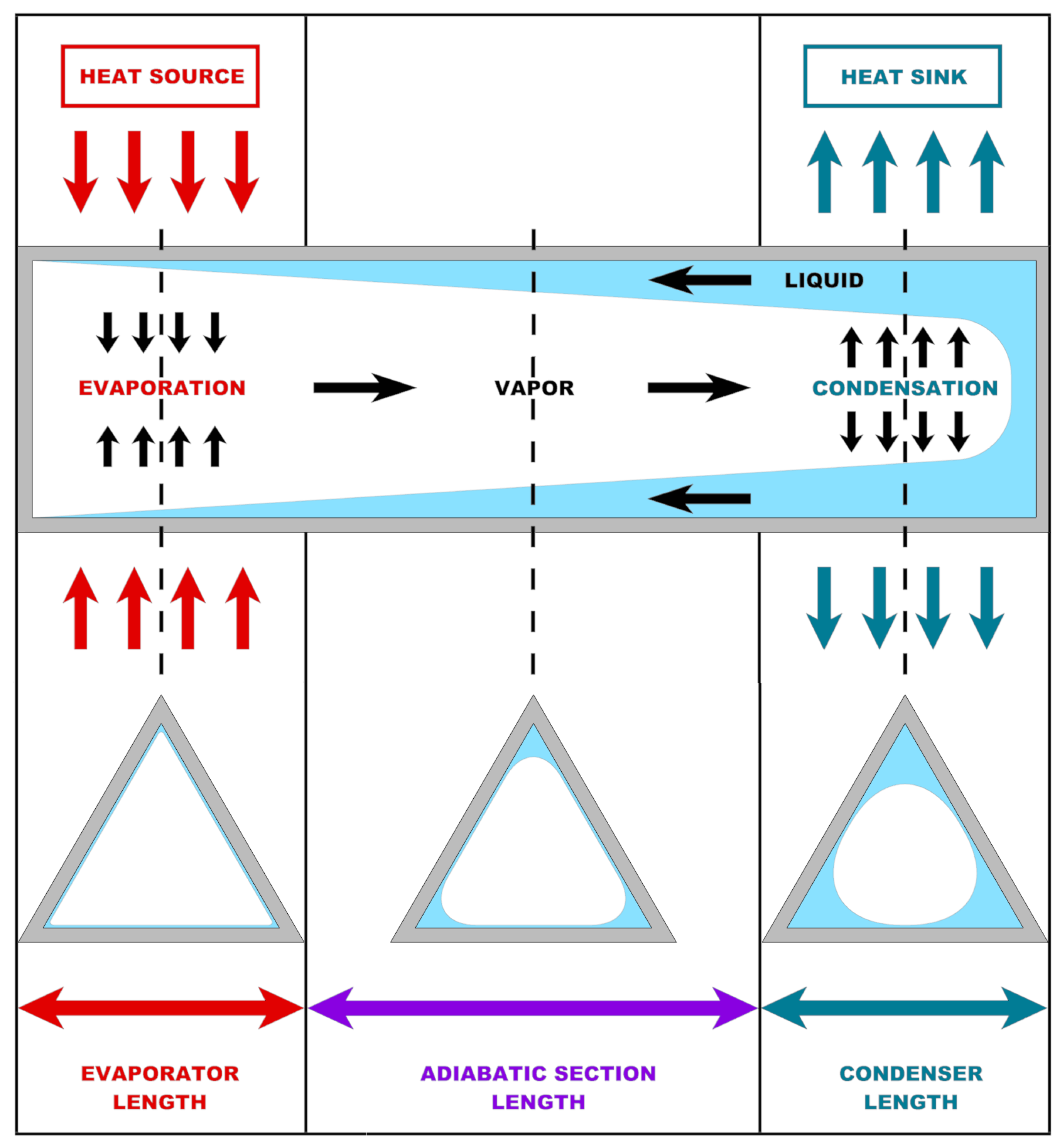
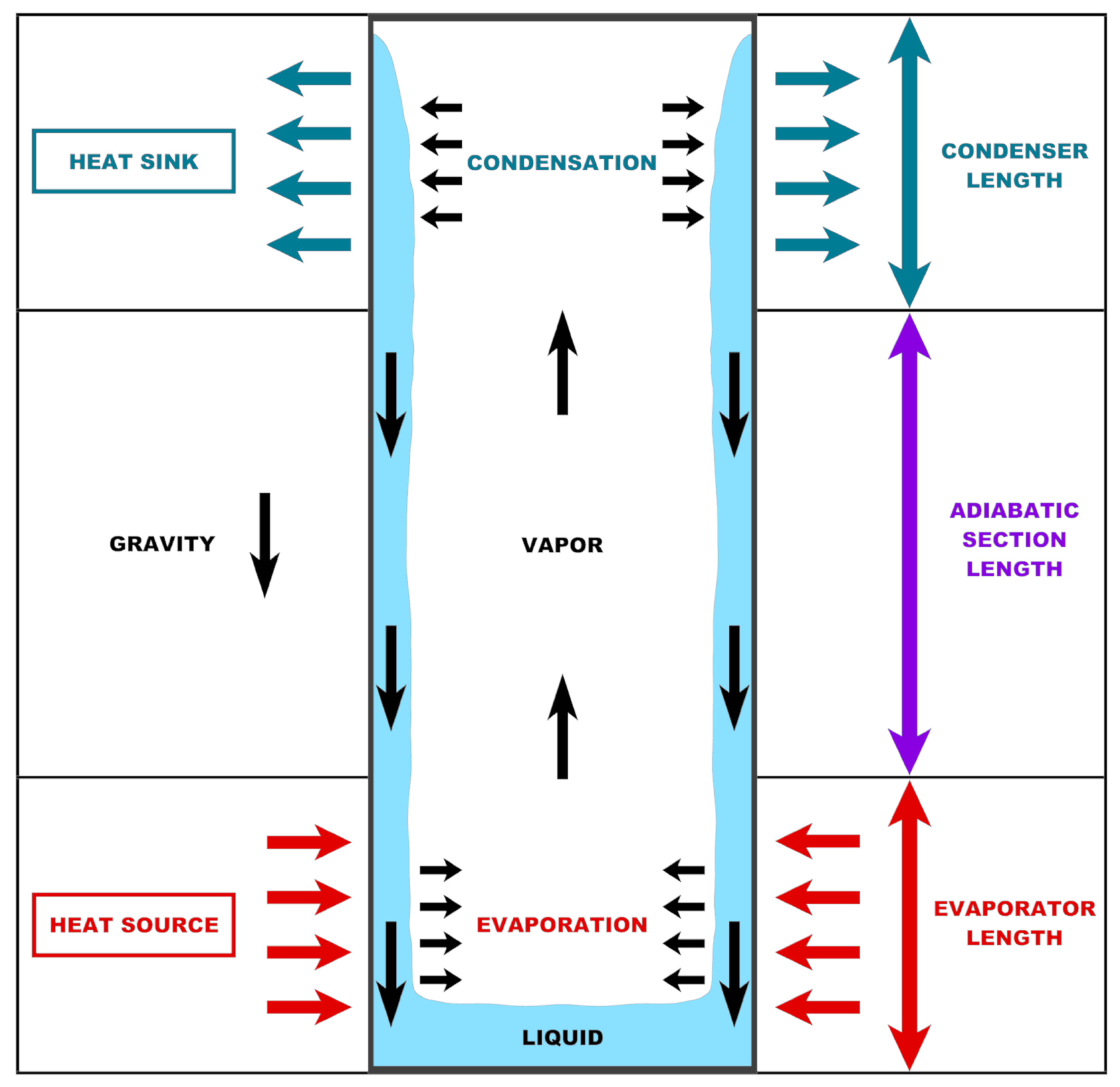
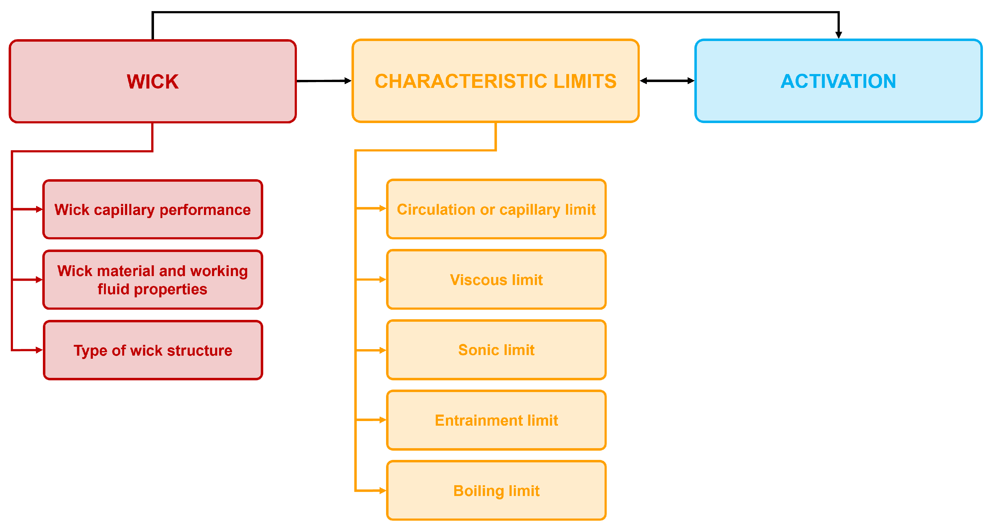
The design and modeling of CHPs with capillary wicks involves addressing several critical points that determine the performance, reliability, and applicability of these devices. In particular, the choice of the wick properties and understanding the characteristic limits that govern fluid flow and phase change within the HP are of paramount importance [91]. Additionally, it is crucial to take into account the effects of the HP activation in the design and modeling phase.
In this section, each of these critical points will be discussed in detail, highlighting their impact on the overall design and modeling of CHPs. Furthermore, the interaction among these critical points will be summarized at the end of the section.

4.1. The Wick

Capillary wicks are fundamental components in CHPs, as they play a crucial role in the transport of the working fluid and the efficiency of heat transfer [92,93]. Their design and modeling are influenced by several factors that determine the overall performance of the HP. These factors can be broadly categorized into wick capillary performance, wick material and working fluid properties, and type of wick structure [94,95].

4.1.1. Wick Capillary Performance

Capillary pressure and permeability are the most important parameters for evaluating the wick performance [96]. In fact, capillary pressure is the driving force moving fluid from the condenser to the evaporator zone, while permeability measures the ease of fluid flow through the wick [97]. Therefore, in the design of a wick structure, it is fundamental to take into account these parameters, in order to optimize the HP performance.
A common method to evaluate the capillary and hydraulic properties of the wick is the measurement of the capillary rise velocity, namely the rate of rise of the liquid through the wick. This quantity can be estimated by measuring the height of rise of the liquid over time or the weight of the liquid absorbed over time by the analyzed wick [98].
Recently, additive manufacturing techniques have emerged as promising solutions to overcome the geometric and performance limitations of traditional wick fabrication methods. In particular, the possibility of creating porous structures with graded pore sizes allows for a more effective trade-off between capillary pressure and permeability. This approach enables better control of the wick structure and may improve the performance of CHPs [99,100].

4.1.2. Wick Material and Working Fluid Properties

The choice of wick material is crucial as it must be compatible with the working fluid and ensure good thermal conductivity [96]. Additionally, the material porosity, pore size, and pore distribution directly affect the permeability and capillary pressure of the wick [101].
In the same way, the choice of a suitable working fluid is also critical, as it must be selected based on the operating temperature range, and it should present suitable thermophysical properties [96]. In fact, surface tension, viscosity, and latent heat of vaporization of the working fluid directly affect the capillary pumping ability and heat transport of the wick [102]. Finally, the wettability of the wick material with respect to the selected working fluid should also be considered.
Therefore, an appropriate modeling of all three involved phases (solid, liquid, and vapor) is fundamental in the design process. Such modeling is typically based on porous media behavior models, as correlations between porosity and permeability or equivalent thermal conductivity, and on fluid phase equilibrium for real substances, using tables or equations of state.

4.1.3. Type of Wick Structure

Wick structures can be classified as either single structures, such as grooved, mesh, and sintered wicks, or composite structures that combine two or more single structures [97]. The geometry of the wick, including the shape and dimensions of channels or pores, directly impacts the flow resistance and capillary pumping ability of the working fluid in the liquid phase [103]. For instance, dual-height superhydrophilic micropost wicks have been developed to enhance the heat transfer coefficient through a thin evaporative film, with a reported 300 % increase compared to single-height micropost wicks [104].
Furthermore, the pore size and the distribution of the pores are also key factors, as smaller pores can generate higher capillary pressure but might reduce permeability [97]. In addition, the surface roughness of the wick impacts wetting properties, fluid flow, and bubble nucleation [96]. Moreover, the wick thickness is also important because it influences the cross-section available for liquid flow and the axial and radial thermal resistances. In fact, an optimal thickness balances efficient fluid supply to the evaporator with manageable thermal resistance [103].
As a consequence, in order to accurately model a wick, it is necessary to use a numerical 3D model able to capture the asymmetries and the peculiarities of each structure [105]. In fact, simplified models cannot provide a detailed representation of the physical phenomena occurring in the wick, but only the overall effects.
Additionally, it is worth mentioning that, in recent years, many innovations have been introduced in the wick design thanks to the new possibilities offered by additive manufacturing [42]. In particular, composite wicks and wicks with microstructures and nanostructures are becoming increasingly popular, thus requiring special attention in the design and modeling phases.

Composite Wicks

Composite wicks offer a solution to the limitations of traditional homogeneous wicks [106]. In fact, homogeneous wicks with a single pore size struggle to balance the need for high capillary pressure (provided by small pores) and high liquid permeability (facilitated by large pores) [107]. Composite wicks, on the other hand, can simultaneously achieve high capillary pressure and high liquid permeability by more easily incorporating both small and large pores [106]. This combination of properties allows for increased liquid flow and enhanced evaporation, ultimately leading to higher heat transfer rates and improved thermal performance [106].
The use of composite wicks is also driven by the need for efficient thermal management in increasingly compact electronic devices [108]. In fact, ultra-thin HPs, with thicknesses of 1   m m or less, require wick structures that can provide sufficient capillary pressure within a limited space [109]. In this context, composite wicks, with their ability to balance capillary pressure and permeability, have emerged as promising solutions for ultra-thin HPs [110]. Therefore, different composite wick designs, such as sintered–grooved wicks, mesh-grooved wicks, and multilayer mesh wicks, have been proposed and tested to enhance the thermal performance of ultra-thin HPs [108]. These designs often combine different materials, such as copper powder and copper mesh, to create a biporous structure with both fine and coarse pores [111,112]. This design strategy aims to optimize both liquid flow and evaporation heat transfer, leading to improved performance compared to conventional designs [106].

Wicks with Microstructures and Nanostructures

Micro and nanostructures in wicks are gaining popularity due to their ability to significantly enhance the performance of the entire HP [113]. In fact, these structures are crucial for optimizing heat transfer by increasing surface area, improving capillary action, and promoting efficient fluid transport [114].
In particular, microstructures offer several advantages, such as an increased surface area for liquid–solid contact and heat exchange, improved capillary forces that enable fluid movement within the wick, and enhanced fluid transport through interconnected pathways [115]. On the other hand, nanostructures add another layer of optimization by enhancing surface wettability, which improves liquid spreading within the wick [116], and they also promote thin-film evaporation, which is a key mechanism for enhanced heat transfer [113]. Additionally, they provide nucleation sites for vapor formation, improving the vaporization process and maximizing heat dissipation [114].
The combination of micro and nanostructures results in materials with superior properties. For instance, multiscale microstructures, including superhydrophilic nanosheets and microparticles, prepared on copper meshes, enhance capillary properties [117]. Furthermore, nanostructured wicks can increase the capillary performance by increasing permeability and decreasing effective capillary radius [116]. However, the increase in porosity makes the effective capillary radius dominate the competition for permeability, which can decrease the capillary performance [116].
These advances are supported by sophisticated characterization methods, such as X-ray microtomography, which allows for detailed 3D analysis of wick structures, or direct numerical simulations, which are used to model the complex transport phenomena in these materials [118]. These tools help researchers understand the impact of various parameters, such as particle size, necking ratio, and porosity on the performance of wicks [118].
Therefore, it can be concluded that the growing popularity of micro and nanostructures in wick materials is due to their ability to optimize heat transfer through improved surface properties, fluid transport, and overall wick performance [116].

4.2. The Characteristic Limits

As previously mentioned, in addition to the wick properties, there are several characteristic limits that define the operational boundaries of a CHP. These limits are critical to ensure that the HP operates efficiently and safely under varying operating conditions.
A summary of simplified models and correlations to consider the working limits can be found in [91].

4.2.1. Circulation or Capillary Limit

The circulation or capillary limit is associated with the fundamental principle that governs the operation of CHPs, namely the development of capillary pressure differences across the sinterface. In fact, the circulation of the working fluid within the HP is driven by the capillary pressure difference, which must exceed the total pressure losses throughout the system [91].
The capillary limit is reached when the capillary forces generated at the interface between the liquid and the vapor are unable to overcome pressure losses due to friction and, in case of unfavorable orientation, to gravity. As a result, the evaporator wick will experience dry-out [91].

4.2.2. Viscous Limit

At low working temperatures, the saturation pressure available in the evaporator zone can be quite low, potentially matching the pressure gradient required to transport vapor from the evaporator to the condenser. In such cases, the total vapor pressure within the vapor region is counterbalanced by opposing viscous forces in the vapor channel. Consequently, the available vapor pressure may not be sufficient to sustain a higher flow rate [91]. This condition is known as the viscous limit, and it typically occurs when the vapor pressure is extremely low.
The viscous limit is most commonly encountered in long HPs, especially during frozen startup conditions or in any case when the working fluid is close to its melting temperature, as the saturation pressure of the fluid remains low [91].

4.2.3. Sonic Limit

The sonic limit is most commonly encountered in liquid metal HPs during startup or low-temperature operation, where vapor densities are extremely low. In fact, under these conditions, the vapor flow may reach sonic speed, thus becoming choked. For most HPs operating at room or cryogenic temperatures, the sonic limit is generally not a concern, except in cases involving very small vapor channel diameters [91].
It is worth mentioning that the sonic limit represents an upper boundary for axial heat transport capacity rather than an immediate cause of evaporator wick dry-out or HP failure. Nonetheless, exceeding this limit results in rising evaporator temperatures and an increasing axial temperature gradient, further compromising the isothermal characteristics typically observed in the vapor region [91].

4.2.4. Entrainment Limit

In a CHP, the liquid and vapor phases flow in opposite directions. This counter-flow generates shear forces at the liquid–vapor interface, which can hinder the return of liquid to the evaporator. Under certain conditions, interfacial waves may form, and if the shear stress overcomes the surface tension of the liquid, droplets can be entrained into the vapor stream. This liquid carryover toward the condenser reduces the amount of working fluid available in the wick, potentially disrupting the operation of the HP [91].

4.2.5. Boiling Limit

When the heat flux in the evaporator becomes too high, the liquid inside the wick can reach its boiling point. This phenomenon leads to the formation of vapor bubbles within the porous structure, which may block the capillary pathways and reduce liquid circulation. As a result, the capillary action is weakened or interrupted, significantly limiting the ability of the HP to transfer heat effectively [91].

4.3. Activation Effects

Activation is another crucial factor in the design and modeling of HPs. In fact, the startup process is influenced by many complex phenomena, such as the heating power, the inclination angle, the convective heat transfer coefficient, and the HP characteristics [119]. As a consequence, the activation effects are particularly complex to model, as they are strongly dependent on the type of HPs and the operating conditions.
It is worth mentioning that the startup process is of paramount importance in HP-cooled reactors, as these devices rely on the transition of the working fluid from a frozen state to a continuous vapor flow, thus necessitating an accurate modeling of the activation phase to ensure the device safety [120].

4.4. Interactions Among the Critical Points in Conventional Heat Pipe Design and Modeling

The three critical points previously discussed, namely the wick, the characteristic limits, and the activation effects are strongly dependent from one another. In fact, under a fixed heat load, the wick capillary performance, its material and working fluid properties, as well as its geometry and structure, directly influence both the characteristic limits of the HP and its ability to activate. Moreover, characteristic limits and activation effects are also interconnected in a bidirectional way. In fact, on the one hand, if the HP fails to activate properly, it may never reach the operating conditions in which its limits are defined. On the other hand, the proximity to one or more characteristic limits can itself hinder or delay the activation process.
A schematic diagram of the interactions among the critical points in CHP design and modeling is illustrated in Figure 8.

5. Modeling of Conventional Heat Pipes with Capillary Wicks

In this section, the main models to predict the behavior and performance of CHPs with capillary wicks are reviewed, with a particular focus on the critical points previously discussed.
The models are classified according to their type. In particular, a distinction is highlighted among: analytical models, numerical lumped parameter models, numerical 2D models, numerical 3D models, and other types of models.
The references presented in this section were found through an accurate research based on keywords in the main databases available online.

5.1. Analytical Models

One of the first analytical models for CHPs was developed by Lips and Lefèvre [121], which extended the analytical model previously developed by Lefèvre and Lallemand [122] for VCHPs to different geometries, including CHPs. In particular, three configurations were analyzed:
  • A copper–water VCHP with a porous wick on both the top and bottom plates.
  • A copper–water VCHP with a porous wick only on the top plate.
  • A copper–water screen-mesh wick CHP.
The thermal model adopted in this study relies on the understanding that, in both VCHPs and CHPs, heat transfer occurs through conduction in the wall and phase change at the interface between the vapor and the capillary structure. Additionally, the body of the HP and its wick are generally either cylindrical or rectangular in shape. This geometric regularity allows for analytical solutions to the thermal problem using Fourier series, assuming a periodic domain. This periodicity may arise naturally, such as along the circumferential direction of a cylindrical HP, or it can be imposed by adiabatic boundary conditions. In fact, a domain with adiabatic boundaries is equivalent to a larger periodic domain, which can be modeled by introducing additional fictitious domains that are symmetrical to the original one with respect to the adiabatic lines. Therefore, proper boundary conditions were applied to each of the analyzed configurations.
On the contrary, the hydrodynamic model employed in this study is grounded in Darcy’s law. Specifically, the equations for the liquid phase are solved within a periodic domain suited for Fourier series analysis, whereas the domain geometry for the vapor phase depends on the particular configuration of the HP.
The equations of the model were validated by comparison with previously acquired experimental data [122] for configuration 2. Moreover, the results obtained using these equations also showed good agreement with those obtained through the transient 3D numerical model of Sonan et al. [123], the same as configuration 2. After validation, the model was used to predict the thermal and hydrodynamic performance of a CHP to predict the properties of the capillary structure from experimental data and to derive analytical expressions for the HP operating limits.
The main innovations of this work are the use of the Fourier transformation to model the HP behavior, which allows to obtain an exact analytical solution, and the derivation of the analytical expressions for the characteristic limits. However, the accuracy of the results may be influenced by the simplifying assumptions required to derive the analytical solution. In fact, since the boundary conditions must be homogeneous to solve the heat transfer equation analytically, the heat sinks are modeled using an imposed heat flux, which represents a limitation of the model. Additionally, the model is steady-state, so it does not take into account the effects of the HP activation and the possibility of a time-varying heat load. Finally, the model was validated only for a copper–water VCHP with a porous wick on the top plate, so its applicability to different types of HPs is uncertain.
Solomon et al. [124] derived an analytical expression for the thermal conductivity of CHPs, which was estimated by equating the heat transport limit to the heat conducted through the pipe.
The heat transport limit is primarily determined by the capillary pressure generated within the wick and the pressure losses associated with phase change, along with frictional losses in both the vapor and liquid flows. In order to prevent dry-out in the evaporator due to insufficient liquid return, the net capillary pressure between the evaporator and condenser must be greater than the combined pressure losses in the vapor and liquid phases. Therefore, the capillary limit is determined by setting the capillary pressure equal to the total pressure losses, while the capillary pressure is determined by assuming the following:
  • The vapor viscous pressure losses are considered, while the inertial effects are neglected.
  • The transition losses of the vapor are not considered.
  • The vapor flow is 1D along the HP length.
Consequently, the HP thermal conductivity can be determined based on the above assumptions.
The analytical expression for the HP thermal conductivity was validated by comparison with experimental results for a copper–water screen-mesh wick CHP subject to different heat loads. The validation results were quite satisfactory for the maximum thermal power tested ( 300 W ), but for lower heat loads the discrepancy was not negligible.
Therefore, this model can be used to make a preliminary estimation of the HP thermal conductivity to be used in more complex models involving other physical aspects. In fact, the HP activation and the characteristic limits, except for the capillary limit, are not taken into account. Additionally, the model was validated only for a copper–water screen-mesh wick CHP, so its applicability to other types of CHPs is uncertain.
The analytical models previously described are summarized in Table 1.

5.2. Numerical Lumped Parameter Models

Zuo and Faghri [125] were the first to model the HP structure as a thermal network, associating a thermal resistance with each of the eight processes that underly the HP operation:
  • Radial heat conduction within the wall thickness of the evaporator.
  • Radial heat conduction within the wick thickness of the evaporator.
  • Vapor flow in the vapor channel which involves heat convection.
  • Axial heat conduction along the wall length of the adiabatic zone.
  • Axial heat conduction along the wick length of the adiabatic zone.
  • Liquid flow through the wick which involves heat convection.
  • Radial heat conduction within the wall thickness of the condenser.
  • Radial heat conduction within the wick thickness of the condenser.
Therefore, the processes can be divided into two categories: those involving pure heat transfer or heat conduction (1, 2, 4, 5, 7, and 8) and those involving heat and mass transfer or heat convection (3 and 6).
All the processes are described by a set of linear, first-order, Partial Differential Equations, which can be solved through the fourth-order Runge–Kutta method (RK4), and allow to obtain the temperatures of the nodal points of the HP. After calculating these temperatures, other parameters of interest, such as thermal fluxes and temperature gradients, can be easily obtained.
After developing the previously described transient network model, the working fluid circulation is analyzed in the temperature-entropy diagram and a new dimensionless parameter, Ψ, is introduced. This factor is defined as the ratio between two other parameters, that are: Φ, which is a group of geometric dimensions of the HP, and Θ, which is a group of thermophysical properties of the working fluid and of the solid material.
The main innovation of this work is establishing that Ψ must be greater than one to ensure circulation of the working fluid, so the geometry of the HP, the solid material, and the working fluid must be compatible. Additionally, the idea of modeling an HP as a thermal network will be the basis for many of the models developed in subsequent years.
The model was validated against the experimental data of El-Genk and Huang [126] for a copper–water screen-mesh wick CHP. The validation results showed that the predictions of the model tend to overestimate the vapor temperature, and the predicted HP transient was slightly faster than the measured one. However, the maximum difference between numerical and experimental data was lower than 5 % for the vapor temperature, so the results obtained through the model can be considered quite satisfactory. Finally, another validation was performed by comparison with a more detailed 2D numerical model [127] and a lumped model [128]. The results showed that the agreement between the network model and the more detailed 2D model was excellent, and the computational cost of the network model was much lower, while the lumped model tended to overestimate the vapor temperature.
However, despite the previously discussed advantages of this network model, there are also some limitations to consider. In fact, the model takes into account only the circulation limit, but the other characteristic limits and the effects of the HP activation are neglected. Furthermore, the model was validated only for a copper–water screen-mesh wick CHP, so its suitability for different types of HPs is uncertain.
Ferrandi et al. [129,130] developed a lumped parameter numerical model able to predict the steady and transient behavior of CHPs. In this model, the solid and fluid domains are discretized into a finite number of control volumes (referred to as “nodes” or “lumps”), each defined by a particular thermodynamic state. These nodes are interconnected through resistive, capacitive, and inductive elements (using the electrical analogy) that represent different physical processes.
The behavior of each node is described by an Ordinary Differential Equation (ODE). Therefore, the HP behavior is described by a set of twentyone ODEs: six for the solid network, ten for the fluidic network, four for the solid/fluid coupling, and one for the liquid/vapor coupling. All these equations are discretized through the finite difference method (FDM) and solved numerically using the LU decomposition with partial pivoting.
The model was validated by comparison with the numerical results of Tournier and El-Genk [131], the experimental data of Huang et al. [132], and the analytical results of Zhu and Vafai [133], for a copper–water-sintered CHP. The validation showed that the discrepancy between the numerical results obtained through the model and the experimental data in [132] was always lower than 15 % , and, in general, the agreement with all the data reported in [131,132,133] was good for both steady and transient operation of the HP.
After validation, the model was employed to evaluate the effect of some parameters on the HP behavior. In particular, the effects of changing the wick thickness, wick porosity, and grain radius were studied. The results of these analyses showed that there is an optimum wick thickness which minimizes the HP thermal resistance, thus improving its performance, and this value is almost independent on the heating power. Furthermore, reducing the wick porosity increases the possibility of dry-out. Finally, the effect of the grain radius on the HP thermal resistance was not significant.
The main innovation of this work lies in applying the lumped parameter approach to both steady and transient regimes. Nevertheless, some physical aspects are not taken into account in the model development, thus leading to a possible reduction in the accuracy of the results. In fact, an ideal gas assumption is applied to the vapor phase, thus neglecting the possible real gas effects, the contribution of the gravitational force is not considered, the effects of the HP activation are neglected, and also the operating limits, except for the entrainment limit, are not considered. Moreover, the verification was performed only for a copper–water-sintered CHP, so the model validity for different types of HPs is uncertain.
Tak and Lee [134] built a transient lumped parameter model, based on that developed by Ferrandi et al. [129,130], for design and performance analysis of CHPs for space nuclear reactors.
In this model, it is assumed that the HP structure can be modeled as an electrical network composed of six nodes for the external solid wall and the wick and of two nodes for the vapor region. The nodes are connected through conductive and convective thermal resistances, and it is assumed that the temperature of the liquid flowing in the wick is always equal to the temperature of the solid part of the wick. Moreover, the vapor is treated as an ideal gas assuming that it reaches thermal equilibrium in a very short time and the effects of gravity are neglected.
The model was validated by comparing the numerical results with literature experimental data for a stainless steel-sodium screen-mesh wick CHP for a space nuclear reactor [135], and this analysis also included the evaluation of all the HP characteristic limits. The validation results showed a very good agreement for both the evaporator and condenser regions in high temperature zones, while the discrepancy was higher in low temperature regions, probably due to the assumption of small vapor temperature gradients along the HP.
The main innovation of this work is the idea of using a simple and fast tool able to estimate the solid and working fluid temperatures along the HP. However, modeling the vapor as an ideal gas with small temperature differences along the HP may not be accurate in some cases. Additionally, neglecting the effects of gravity and those of the HP activation may cause a loss of accuracy in some applications. Finally, the model was validated only for a stainless steel–sodium screen-mesh wick CHP, so its suitability for other types of HPs is uncertain. This model builds on the same principles as those discussed previously. In fact, the idea is again to divide the HP Kolliyil et al. [136] developed a lumped parameter transient numerical model for CHPs, which also includes the Marangoni effect, into nodes connected to each other through resistive, capacitive, and inductive elements, in order to form a thermal network. However, in this case the basic model is improved by the inclusion of the Marangoni effect, namely of the mass transfer across the interface between the liquid phase and the vapor due to the surface tension gradient.
As in previous models, the operation of the HP is described by a set of linear ODEs, which can be solved using Euler’s explicit or implicit method.
The validation was performed by comparing the numerical results obtained using the model with the experimental data of Huang et al. [132] for a copper–water screen-mesh wick CHP. This analysis showed a quite good agreement between numerical and experimental results, with a maximum discrepancy around 3.3 % .
After validation, a sensitivity analysis about the dependence of the HP performance on the most common design parameters was performed. In particular, it was found that the overall HP thermal resistance increases when the wick thickness and the effective wick porosity increase, while it decreases when the heat input increases. However, at high heat inputs, the size of the HP must increase, as the minimum diameter to avoid dry-out is greater. Moreover, it was found that using self-rewetting fluids as working fluids significantly improves the HP performance compared to using water.
The main innovation of this work is the consideration of the Marangoni effect in the HP modeling. However, this model presents the previously discussed limitations which affect almost all the presented lumped parameter models. In fact, the vapor phase is approximated using the ideal gas law, the effects of gravity are neglected, and the effects of the HP activation and its operating limits are not considered. Additionally, the model was validated only for a copper–water screen-mesh wick CHP, so its applicability to different HPs is uncertain.
Hu et al. [137] developed a lumped parameter transient numerical model, based on those of Ferrandi et al. [129,130] and Kolliyil et al. [136], particularly focusing on ultra-long lithium HPs with ultra-high working temperature for HP-cooled reactors.
The idea behind this model is again to divide the HP into nodes forming a thermal network, but in this case, the Marangoni effect, bending effect, and different vapor flow patterns and Mach numbers are taken into account.
Also, in this case, the HP operation is described by a set of linear ODEs, which are discretized using the FDM.
The model was validated by comparison with two literature models of Tournier and El-Genk [138] for an ultra-long and ultra-high temperature molybdenum-lithium CHP, and the results showed a very good agreement, with a maximum discrepancy below 1 % .
After validation, the performance of the same HP used for validation was analyzed under different heat loads, to understand the influence of the bending structure, Marangoni flow, and adiabatic section length on the HP operation. The results of this analysis showed that the vapor pressure loss due to bending is approximately 22– 23 % of the total pressure drop, while bending does not significantly affect the liquid pressure drop. Moreover, the Marangoni effect can have a significant influence on the liquid flow and the capillary limit of the HP, but this effect is reduced when the working temperature increases. Finally, when the adiabatic section length and the vapor temperature are not sufficiently high, bending has a greater influence on the HP pressure loss.
The main innovation of this work is the consideration of the effects of bending on the performance of ultra-long HPs. Nevertheless, also this model assumes ideal gas properties for the vapor, neglects the effects of gravity and those of the HP activation, and takes into account only the capillary limit. Additionally, as this model was targeted and validated only for ultra-long and ultra-high temperature molybdenum-lithium CHPs, its suitability for other types of HPs is uncertain.
Caruana et al. [139] developed a multi-node lumped parameter model able to predict the steady and transient behavior of CHPs. Based on the works of Ferrandi et al. [129,130], this model includes real gas effects and accounts for gravity by considering the impact of orientation on HP performance.
As in previous models, the HP is divided into nodes with distinct thermophysical properties. The nodes are interconnected by means of resistive, capacitive, and inductive components, constituting a thermal network. Therefore, in this case, the behavior of the HP is also described by a set of ODEs, which are discretized using the forward FDM and iteratively solved.
The model was validated by comparison with experimental data acquired by the authors, for a copper–water sintered CHP subject to seven cycles of thermal charge and discharge. The comparison showed that the discrepancy between numerical and experimental results was acceptable in the last three cycles, with a maximum error of around 5.3 % for both the evaporator and condenser wall temperatures. On the contrary, the difference was greater in the first four cycles, as this model does not take into account the effects of the HP activation.
After validation, the model was used to evaluate whether modeling the vapor as a real gas rather than an ideal gas leads to significant differences in the values of the parameters of interest. Therefore, four HPs using different working fluids were simulated, both with the real and ideal gas vapor models. The results of this analysis showed that when using water and ammonia as working fluids, the difference between the ideal and real gas modeling is negligible, both in terms of vapor temperatures and pressures. However, when using acetone and HFC134a refrigerant, there is a significant difference in the vapor pressures between the ideal and real gas models.
The main innovations of this work are the considerations of the effects of gravity (orientation angle) on the HP performance and the real gas vapor model. However, as previously mentioned, the effects of the HP activation are neglected and the operating limits are not evaluated, thus possibly reducing the reliability of the numerical results. Additionally, the model was validated only for a copper–water-sintered CHP, so its suitability for other applications is uncertain.
The numerical lumped parameter models previously described are summarized in Table 2.

5.3. Numerical 2D Models

Mahjoub and Mahtabroshan [140] developed a numerical Computational Fluid Dynamics (CFD) model for the heat transfer analysis of CHPs, based on the Finite Volume Method (FVM). This model can be used for the design and performance prediction of CHPs with cylindrical external structure as the mass, momentum, and energy conservation equations are written in cylindrical coordinates. Moreover, the flow inside the HP is assumed to be 2D, steady-state, incompressible, and laminar.
The validation was performed by comparison with the experimental data of Faghri [141] and the numerical results of Nouri-Borujerdi and Layeghi [142] for two copper–water screen-mesh wick CHPs, showing a quite satisfactory agreement for both geometries.
After validating the model and assessing mesh independence, the effect of changing some of the HP geometrical and structural parameters on its performance was evaluated, showing that the HP thermal resistance increases when increasing the wick porosity, while it decreases when the thermal conductivity of the wall and the radius of the HP increase.
The most important innovation of this work is the use of a CFD model for predicting the thermal behavior and performance of an HP. However, the described model is not suitable for non-cylindrical geometries, 3D effects on the HP behavior are not considered, the steady-state assumption does not allow to take into account the effects of the HP activation and the possibility of time-varying heat loads, and none of the HP characteristic limits is considered. Additionally, the model was validated only for copper–water screen-mesh wick CHPs, so its applicability to different devices is uncertain.
Thuchayapong et al. [143] developed a steady-state 2D numerical model to evaluate the thermal performance of CHPs. In this model, the HP system is divided into four regions: the vapor core, the wick, the external wall, and the heat sink. Thermal power is uniformly applied to the evaporator using a tape heater, while the condenser is cooled by water.
The model is based on the following assumptions:
  • Both the liquid and vapor flows are incompressible and laminar.
  • The HP operation has reached a steady state.
  • The wick is entirely filled with liquid, and its porosity and permeability are uniform.
  • The working fluid is Newtonian and its thermophysical properties are calculated at the operating temperature, which is considered constant.
  • The gravitational effects are neglected.
The model is based on the mass, momentum, and energy conservation equations, which are discretized using the Finite Element Method (FEM) and then solved numerically.
The validation was performed by comparison with the numerical results of Tournier and El-Genk [131] and the experimental data of Huang et al. [132] for a copper–water screen-mesh wick CHP, showing that the standard deviations of vapor and wall temperature with respect to the results in [131] were 0.64 °C and 2.59 °C, respectively, while those with respect to the data in [132] were 0.48 °C and 1.78 °C, respectively.
The main innovation of this work lies in modeling the capillary radius as a linear function along the length of the HP. Specifically, the radius is set equal to the effective pore radius of the wick at the evaporator, and to the vapor core radius at the condenser. However, the assumptions of constant operating temperature and negligible gravitational effects can reduce the reliability of the results. Furthermore, as the model only takes into account the steady-state operation of the HP, the effects of the HP activation and the possibility of time-varying heat loads are not considered. Additionally, 3D effects on the HP behavior are neglected and none of the characteristic limits is mentioned in this work. Finally, the model was validated only for a copper–water screen-mesh wick CHP, so its suitability for other types of HPs is uncertain.
Mahdavi et al. [144,145] developed a numerical CFD model based on the FVM to analyze the behavior of a high-temperature HP with complex geometry, taking into account also compressibility of the working fluid and viscous dissipation.
The model is based on the following assumptions:
  • The HP is modeled as a 2D axisymmetric system.
  • Vapor and liquid flows are laminar and stationary.
  • Gravitational forces are negligible.
  • The wick is entirely filled with liquid, its porosity and permeability are uniform, and it is considered homogeneous and isotropic.
  • Evaporation and condensation occur only at the liquid–vapor interface.
  • The energy equation for the vapor phase includes pressure work and viscous dissipation effects.
  • The saturation temperature at the liquid–vapor interface is determined as a function of pressure using the Clausius–Clapeyron equation.
  • Density variations in the vapor phase are included using the ideal gas model.
  • All other properties of the working fluid are constant and they are evaluated at the HP operating temperature.
As the system is assumed to be axisymmetric, the governing equations of the model are written in cylindrical coordinates and they are solved through the Algebraic Multigrid Methods, with the diffusion and convection terms discretized using central difference and second-order upwind schemes, respectively.
The model was validated by comparison with the experimental results of Ivanovskii et al. [146] and with the numerical predictions of Chen and Faghri [147] for a stainless steel–sodium screen-mesh wick CHP. These analyses showed that the model results present a good agreement with the experimental data of Ivanovskii et al. in the evaporator and in the adiabatic zone, and they present a good agreement with the numerical predictions of Chen and Faghri in the condenser section.
After validation, the model was applied to the same HP used for validation. All the heat transfer limitations associated with the HP geometry, working fluid, wick structure, and operating temperature were taken into account, and the results indicated that the thermal resistance decreases as the operating temperature and vapor core radius increase and as the heat input decreases.
The main innovation of this work is the consideration of the compressibility of the working fluid and viscous dissipation. Nevertheless, the 2D steady-state modeling does not take into account the 3D effects, the HP activation, and time-varying heat loads. Moreover, the vapor phase is approximated using the ideal gas law, and the effect of gravity is neglected. Finally, the model verification was performed only for a stainless steel–sodium screen-mesh wick CHP, so its validity for different types of HPs is uncertain.
Hussain and Janajreh [148] developed a numerical CFD model based on the FEM to analyze the performance of cylindrical CHPs. This 2D axisymmetric stationary model is based on the mass, momentum, and energy conservation equations and it employs a single-phase approach, so that in the vapor core there is only vapor flow, and in the wick, there is only liquid flow. Taking into account these simplifications, the model can be used to calculate the overall HP thermal resistance, as well as the temperature profiles in the external wall region of the HP.
In order to solve the equations, the solver applies Newton–Rhapson iterations to the initial guess, until reaching a convergence of the solution, which is considered achieved when the relative error between two consecutive iterations is lower than 10 4 .
The model validation was obtained by comparison with the experimental results of Faghri [149] for a copper–water sintered HP, showing a very good agreement between numerical predictions and experimental data for the external wall temperature profile.
After validation, a sensitivity analysis on the main design parameters was performed, and the results showed that as porosity increased, the absolute thermal resistance also rose due to reduced conductivity in the liquid–wick region. Moreover, the thermal resistance decreased with an increase in internal radius due to the greater cross-sectional area enhancing heat transfer, while it did not change when modifying the heat load.
Therefore, assuming ideal operating conditions and taking into account all the introduced simplifications, this model can be considered quite reliable for preliminary HP design. However, the 2D steady-state formulation does not allow us to consider the 3D effects, the HP activation, and the possibly time-varying heat loads. Moreover, the model is suitable only for cylindrical geometries and none of the HP characteristic limits is considered in these analyses. Finally, the model was validated only for a copper–water-sintered CHP, so its suitability for other types of HPs is uncertain.
The numerical 2D models previously described are summarized in Table 3.

5.4. Numerical 3D Models

Kaya and Goldak [150] developed a 3D numerical model, which is able to predict the thermal performance of a CHP and is based on the following assumptions:
  • The process has reached a steady state.
  • Radiative heat exchanges, gravitational effects, and the possibility of boiling the liquid are neglected.
  • The working fluid is Newtonian and incompressible, but density variations due to temperature changes in the vapor are considered.
  • The vapor phase is approximated using the ideal gas law.
  • The wick is completely filled with liquid.
In this model, the conservation equations are discretized using the FEM, which allows us to calculate the wall temperature, the vapor pressure, and the vapor velocity profile.
The validation was firstly performed by comparison with the experimental data and numerical results of Schmalhofer and Faghri [151] for a copper–water screen-mesh wick HP subject to uniform and non-uniform heat loads. In particular, when the heat load was uniform, the results of outer wall temperature were satisfactory, except for some small discrepancies at both ends of the HP, while for the case of non-uniform heat loads, the discrepancies were more evident, especially in the evaporator zone.
However, in [151], the experimental data for the outer wall temperature in the evaporator zone are not provided, so the validation in this region was performed only by comparison with numerical results. Therefore, the model developed in this work was also validated by comparison with experimental results acquired by the authors, again using a copper–water screen-mesh wick HP subject to different operating conditions.
The results of this second validation showed that, in the case of natural convection cooling, the agreement between numerical and experimental results for the outer wall temperature was satisfactory, except for the condenser region, while in the case of liquid cooling, the agreement was good along all the HP length.
Finally, after validation, the vapor pressure, the axial vapor velocity, and the capillary limit were also evaluated.
The main innovations of this work are as follows: the 3D formulation, which allows us to study HPs subject to non-uniform heat loads; the calculation of the vapor temperature from the energy equation, which allows us to model also high-temperature HPs; the modeling of the liquid flow inside the wick, which allows us to evaluate the capillary limit and leads to a better estimation of the temperature field.
Nevertheless, the steady-state formulation does not allow for to study of the effects of the HP activation, as well as the behavior of an HP subject to a time-varying heat load. Moreover, modeling the vapor as an ideal gas and neglecting the effects of gravity may lead to a loss of accuracy when using some working fluids in particular conditions. Additionally, all the characteristic limits, except for the capillary one, are not considered in the model formulation. Finally, the model validation was performed only for copper–water screen-mesh wick CHPs, so its applicability to different devices is uncertain.
Huang and Chen [152] developed a 3D transient numerical model for fast simulations of CHPs, which is based on treating the vapor using a single-node lumped parameter approach and solving the liquid flow and the conduction in the solid regions using a Lattice Boltzmann Method (LBM). Consequently, in this model, the vapor is not directly simulated, but only the accumulative mass and energy equations are solved, and a single saturated state property is used to describe the whole vapor.
This approach was chosen because it allows us to significantly reduces the computational cost of the numerical simulations, as the vapor core could represent a significant part of the total HP volume, thus its simulation would require a notable increase in the number of cells. Additionally, incorporating an algorithm for non-uniform meshes [153] avoids the issues due to large aspect-ratio cells, and using parallel computing allowed further reduction in the computational time, leading it to be 50 times lower than that required by the complete vapor simulation.
The model validation was performed by comparison with the numerical predictions and experimental data of Mistry et al. [154] for a stainless steel–water screen-mesh wick CHP, and with the experimental results of Huang et al. [132] for a copper–water screen-mesh wick CHP, showing a quite satisfactory agreement also for time-varying heat loads.
Nevertheless, despite this model being a good compromise between accuracy and computational cost, it is worth mentioning that it does not take into account the HP activation effects and its characteristic limits. Additionally, the model validation was performed only for a copper–water and a stainless steel–water screen-mesh wick CHPs, so its suitability for different types of HPs is uncertain.
The numerical 3D models previously described are summarized in Table 4.

5.5. Other Types of Models

Zimmermann et al. [155] developed an advanced conduction-based thermal model for CHPs, that addresses the limitations of conventional approaches by incorporating critical aspects of vapor phase dynamics. This model focuses on accurately representing the behavior of the vapor core by taking into account the velocity components perpendicular to the main vapor flow. Moreover, it also accounts for the temperature-dependent effective thermal conductivity of the vapor core, which is determined using the local vapor temperature, in order to dynamically evaluate the thermophysical properties.
In practice, an analytical expression for calculating the axial pressure gradient within the vapor core was initially developed, and it was validated using detailed 2D CFD simulations for various HP sizes and Reynolds numbers. Next, under the assumption of saturation conditions, this pressure drop analytical expression was employed to determine the temperature gradient, which was then used to derive an expression for the effective thermal conductivity of the vapor core. Finally, this result was integrated into a thermal HP model previously developed by the same authors [156], which also incorporates the thermal resistance associated with evaporation from the porous wick structure.
The model was calibrated and validated against the experimental data from Prasher [157] for a copper–water-sintered CHP, and it was further compared to Prasher’s conduction-based model [157]. The comparison between the present model and that of Prasher revealed substantial improvements in the accuracy of the numerical predictions with respect to the experimental results, particularly in capturing the effects of non-Poiseuille flow and temperature gradients within the vapor core.
The main innovation of this work is the inclusion of the phase change thermal resistance at the liquid–vapor interface, based on a detailed dataset characterizing sintered wick structures. Nevertheless, also this model presents some limitations that may affect the accuracy of the results. In fact, it relies on calibration parameters obtained through experimental data, thus resulting in a possible loss of generality. Moreover, an ideal gas assumption is applied to the vapor phase, thus leading to a loss of accuracy when using some particular working fluids. Additionally, the effects of the HP activation and its characteristic limits are not considered. Finally, the validation was performed only for a copper–water-sintered CHP, so the model suitability for different applications is uncertain.
Guo et al. [158] presented a simplified transient numerical model to explore the startup performance of high-temperature HPs, with a particular focus on their application in HP-cooled reactors. In fact, high-temperature HPs are fundamental in such systems, as they provide a reliable mechanism for transferring heat away from the reactor core. In particular, during the startup phase, the working fluid faces a transition from a frozen state to a molten and vaporized state. Therefore, understanding the heat and mass transfer processes involved is crucial for the modeling of this type of reactor.
For this reason, the authors proposed a model which combines the two-zone and network approaches. In particular, the two-zone model divides the HP into distinct hot and cold regions, accounting for the differences in temperature, phase change, and flow behavior, while the network model simplifies the heat conduction by breaking the HP into discrete nodes and calculating the heat transport across them. By integrating these two methods, the proposed model is able to predict the vapor flow, pressure drop, and temperature drop in the vapor core. Additionally, all the characteristic limits are evaluated, and the fundamental requirements for successful activation of the HP are stated, defining a lower and an upper limit of the heating power.
The validation was achieved by comparing the numerical results with experimental data acquired by the authors for a high-temperature stainless steel–potassium screen-mesh wick CHP at different heating powers. The comparison of simulated and experimental results showed good agreement in predicting wall temperature distributions, vapor flow, and phase change processes.
The main innovation of this work is the decoupling of vapor flow, phase change, and heat conduction processes, which allows for efficient simulation without sacrificing accuracy. Furthermore, this approach enables the prediction of critical conditions for successful activation, such as the minimum heating power required to transition the HP from the frozen state to stable operation. However, this model also presents some limitations. In fact, it assumes 1D laminar vapor flow, thus leading to a possible loss of accuracy in specific scenarios. Additionally, as the model is designed for high-temperature systems and it was validated only for a stainless steel–potassium screen-mesh wick CHP, its applicability to different types of HPs is uncertain.
Huaqi et al. [159] developed a set of transient models for the thermal analysis of high-temperature HPs, consolidating and improving the previously existing literature models, with a particular focus on applications in HP-cooled microreactors. In fact, these reactors typically employ high-temperature HPs with alkali metals as working fluids, in order to efficiently remove heat and ensure safe operation under different operating conditions, including startup, shutdown, and accident scenarios. In particular, this study emphasizes the importance of accurately simulating the startup process from a frozen state, as this type of working fluid solidifies at room temperature.
In order to address the complexity of the startup process, the authors developed the previously mentioned improved set of models, which includes three stages of transient behavior: the free molecular flow regime, the transitional flow regime, and the continuous flow regime. In particular, the free molecular model focuses on 1D heat conduction during the initial stage when vapor density and convective effects are negligible; the intermediate transition flow model builds on the flat-front model of Cao and Faghri [127], coupling it with the HP operating limits to account for scenarios where heat input exceeds the HP capacity; and the continuous flow model employs a 2D thermal resistance network to simulate the stable heat transfer processes during normal operation. Consequently, these models aim to achieve a balance between computational efficiency and physical accuracy, making them suitable for system-level analysis.
The validation of these models was performed by comparison with the experimental data of Faghri [149] and of Ponnappan [160] for a high-temperature stainless steel–sodium screen-mesh wick CHP, and the numerical results showed a very good agreement with the experimental data, with deviations lower than 3 % . Furthermore, the models were applied to the Kilopower space reactor system tested by Poston et al. [161], demonstrating their ability to predict startup characteristics, transient responses to load changes, and reactivity insertions. In fact, the simulated results showed a very good agreement with the experimental data, with errors below 2 % .
The main innovation of this work is the integration of detailed transient heat transfer processes into a computationally efficient framework. In fact, by addressing the limitations of previous models, such as neglecting the HP operating limits or oversimplifying the flow regimes, the authors provide a robust tool for analyzing the dynamic behavior of high-temperature HPs in microreactor systems. However, these models were developed for high-temperature HPs and they were validated only for a stainless steel–sodium screen-mesh wick CHP, so their applicability to different types of systems is uncertain.
Scigliano et al. [162] developed a numerical tool for the simulation of the behavior and performance of CHPs, which could be easily integrated into a conceptual design activity flow. In order to achieve this objective, a numerical ANSYS Parametric Design Language (APDL) code [163] was used. In particular, the APDL tool employs a lumped parameter model based on the electrical analogy to model the HP performance, representing thermal resistances, capacitances, and inductances within a network framework. This approach simplifies the transient thermal analysis while ensuring computational efficiency.
The validation of the model was performed by testing two different case studies for aerospace applications. The first one involved the use of high-temperature nickel–potassium sintered HPs for cooling the leading-edge region of a hypersonic aircraft, while the second one involved the use of a copper–water sintered HP for managing thermal loads in a small low Earth orbit satellite.
In particular, for the hypersonic aircraft application, the study examines the STRATOFLY MR3 [164], a high-speed civil passenger aircraft designed to cruise at Mach 8. In fact, the leading-edge areas of the air intake experience extreme aerodynamic heating due to their small radii, necessitating highly efficient cooling systems. Therefore, a dual-channel high-temperature nickel–potassium-sintered CHP configuration integrated into the leading-edge structure of the aircraft is proposed. In particular, in this case study, the numerical subtractive heat fluxes results obtained using the APDL code were compared with those obtained through parametric FEM analyses, showing a quite good agreement.
The second case study addresses the thermal challenges of a 2U CubeSat. In fact, due to their compact size, limited surface area, and increasing power densities, CubeSats face significant thermal management issues, particularly in dissipating heat from printed circuit boards. Therefore, using HPs for their thermal control seems to be a good solution. In particular, in this case study, the numerical temperature results obtained using the ADPL code were compared with experimental data acquired by the authors, which reproduced a literature experiment of a copper–water-sintered HP integrated into a 2U CubeSat structure and tested in a thermally controlled environment with a heat source able to generate thermal power [165]. Also, in this case, the numerical results showed quite a good agreement with respect to the experimental data, with a maximum discrepancy of around 8 % .
It is worth noticing that the effects of the HP activation are considered in the first case study, and the HP characteristic limits are taken into account in the second application, thus addressing the most common issues of the previously analyzed models. Additionally, this model was tested on two very different HP configurations, thus showing its suitability for a wide range of applications.
The main innovation of this work is the use of a very versatile numerical code capable of predicting the behavior and performance of different CHP configurations when they are integrated into more complex systems. However, at this stage, the use of this code requires some expertise, resulting in it being very difficult to employ for those who have not received specific training.
The other types of models previously described are summarized in Table 5.

6. Discussion

In this work, different modeling approaches employed to predict the thermal behavior and performance of CHPs with capillary wicks were presented, identifying the strengths and limitations of each model, with a particular focus on the critical points in CHP design and modeling.
This study highlighted that analytical models are able to provide closed-form solutions, but they rely on many simplifying assumptions on the HP geometry and structure which limit their use to very specific cases. Conversely, numerical lumped parameter models are ideal for parametric studies and for the preliminary design phase, as they excel in computational efficiency. In fact, these models are based on dividing the HP into a few nodes or tens of nodes and solving the governing equations on each node. Therefore, due to the small number of nodes, lumped parameter models can predict the HP behavior in a relatively short time, which can range from minutes to hours depending on the application, the discretization method, the software, and the hardware used for the numerical calculations. However, in these models, steady-state behavior of the HP, ideal gas vapor modeling, and negligible gravitational forces are often assumed. Additionally, the operating limits are taken into account only in a limited number of cases. On the other hand, even if many numerical 2D and 3D models share similar limitations with lumped parameter models, their main advantage is that they do not capture only the overall HP behavior, but they are able to describe the detailed physical phenomena occurring inside the system, such as the complex processes taking place in the wick structure. Nevertheless, their high computational costs and complexity often prevent their widespread adoption in practical engineering applications. In fact, these models rely on dividing the computational domain into cells and solving the governing equations on each cell. Depending on the application and the required simulation accuracy, the number of cells can range from tens of thousands for very simplified applications to millions for extremely accurate CFD simulations. Therefore, numerical 2D and 3D models can take days or weeks to predict the behavior of an HP. Moreover, extensive validation is required for these models due to their dependence on empirical correlations and assumptions about boundary conditions. Finally, other types of models that combine different approaches have been developed, but they are usually suitable for very specific applications and require good expertise to be employed.
Therefore, despite some significant advancements that have been made in this field, many challenges remain. In particular, capturing the transient behavior of CHPs during activation and under varying operating conditions is an area that demands further research. Similarly, addressing 3D effects such as non-uniform heat loads and complex geometries requires advanced modeling techniques that necessitate a balance between accuracy and computational feasibility. Additionally, many models oversimplify thermophysical properties and boundary conditions, highlighting the need for experimental data to refine these parameters and improve the model’s accuracy. Therefore, the complex interaction between liquid and vapor under varying heat fluxes and orientations could be more effectively addressed using hybrid models that combine analytical and numerical techniques, supported by extensive experimental validation.
Additionally, it is worth mentioning that emerging applications, such as space exploration and electronics cooling, further emphasize the importance of robust numerical models capable of accommodating different operating conditions and configurations. Therefore, the idea of integrating multi-physics approaches, while exploiting ML and AI techniques, offers promising opportunities for the development of this field. In fact, data-driven techniques can complement physics-based models by uncovering patterns and correlations that traditional methods may overlook. However, ensuring data quality and robust validation protocols is critical for reliable predictions. Moreover, scaling models from laboratory experiments to industrial applications remains a challenge due to factors such as manufacturing tolerances, environmental fluctuations, and dynamic thermal loads.
Finally, the development of increasingly accurate models should primarily support the design of innovative HPs capable of overcoming current technological limitations. For this reason, future research should focus on how to address the most critical aspects affecting HP performance rather than simply refining existing modeling approaches.

7. Conclusions and Future Directions

In this review, a detailed analysis of the modeling approaches for CHPs with capillary wicks has been provided, particularly focusing on the innovations, validation methods, and limitations of the presented models. The key findings can be summarized as follows:
  • Numerical lumped parameter models remain the most widely used due to their simplicity and efficiency, even if they often rely on significant assumptions that limit their accuracy.
  • Numerical 2D and 3D models could offer a more accurate representation of CHP behavior, but they require a much higher computational effort.
  • The most common limitations in existing models are the accurate modeling of the vapor behavior, gravitational effects, transient conditions, and operating limits.
Therefore, in order to address the current literature gaps, future research should focus on developing comprehensive models that
  • Treat the vapor as a real gas rather than as an ideal gas.
  • Take into account the gravitational force, in order to consider the effects of the orientation angle on the HP performance.
  • Consider the HP transient behavior, particularly during the activation phase.
  • Take into account all the HP characteristic limits.
These models should be validated across a broad spectrum of conditions to ensure their robustness and applicability.
Additionally, the integration of AI and ML techniques holds significant potential to enhance predictive capabilities and streamline the modeling process. In fact, by training on experimental datasets, these methods can identify complex patterns and offer insights that physics-based models alone cannot achieve.
Finally, improving the scalability of CHP models to industrial applications is fundamental. Therefore, future efforts should prioritize incorporating real-world factors such as manufacturing variations, environmental changes, and dynamic thermal loads. In particular, the adoption of hybrid modeling frameworks that combine analytical and numerical approaches, incorporating experimental validation, is recommended to bridge the existing knowledge gaps and advance the reliability and performance of CHPs in various engineering fields.

Author Contributions

Conceptualization, R.C.; methodology, R.C.; investigation, R.C.; writing—original draft preparation, R.C.; writing—review & editing, R.C. and M.G.; supervision, M.G. All authors have read and agreed to the published version of the manuscript.

Funding

This research received no external funding.

Data Availability Statement

Not applicable.

Conflicts of Interest

The authors declare no conflicts of interest.

Abbreviations

The following abbreviations are used in this manuscript:
1DOne-dimensional
2DTwo-dimensional
3DThree-dimensional
AIArtificial intelligence
ANNArtificial Neural Network
APDLANSYS Parametric Design Language
CFDComputational Fluid Dynamics
CHPConventional Heat Pipe
FDMFinite Difference Method
FEMFinite Element Method
FVMFinite Volume Method
HPHeat Pipe
LBMLattice Boltzmann Method
LHPLoop Heat Pipe
MHPMicro Heat Pipe
MLMachine Learning
ODEOrdinary Differential Equation
PHPPulsating Heat Pipe
RHPRotating Heat Pipe
RK4Fourth-order Runge–Kutta method
THPThermosyphon Heat Pipe
VCHPVapor Chamber Heat Pipe

References

  1. Webb, R.L.; Kim, N. Enhanced Heat Transfer. Taylor & Francis. 2005. Available online: https://www.dl.begellhouse.com/download/issue/30ac7f105c8e675a/sample.pdf (accessed on 27 February 2025).
  2. Vasiliev, L.L. Heat pipes in modern heat exchangers. Appl. Therm. Eng. 2005, 25, 1–19. [Google Scholar] [CrossRef]
  3. Firouzfar, E.; Attaran, M. A review of heat pipe heat exchangers activity in Asia. Int. J. Chem. Mol. Eng. 2008, 2, 278–283. [Google Scholar]
  4. Vasiliev, L. Micro and miniature heat pipes–Electronic component coolers. Appl. Therm. Eng. 2008, 28, 266–273. [Google Scholar] [CrossRef]
  5. Tang, H.; Tang, Y.; Wan, Z.; Li, J.; Yuan, W.; Lu, L.; Li, Y.; Tang, K. Review of applications and developments of ultra-thin micro heat pipes for electronic cooling. Appl. Energy 2018, 223, 383–400. [Google Scholar] [CrossRef]
  6. Khalid, S.U.; Babar, H.; Ali, H.M.; Janjua, M.M.; Ali, M.A. Heat pipes: Progress in thermal performance enhancement for microelectronics. J. Therm. Anal. Calorim. 2021, 143, 2227–2243. [Google Scholar] [CrossRef]
  7. Shukla, K. Heat pipe for aerospace applications—An overview. J. Electron. Cool. Therm. Control 2015, 5, 1. [Google Scholar] [CrossRef]
  8. Zhao, X.; Su, L.; Jiang, J.; Deng, W.; Zhao, D. A review of working fluids and flow state effects on thermal performance of micro-channel oscillating heat pipe for aerospace heat dissipation. Aerospace 2023, 10, 179. [Google Scholar] [CrossRef]
  9. Babu, E.; Reddy, N.C.; Babbar, A.; Chandrashekar, A.; Kumar, R.; Bains, P.S.; Alsubih, M.; Islam, S.; Joshi, S.K.; Rizal, A.; et al. Characteristics of pulsating heat pipe with variation of tube diameter, filling ratio, and SiO2 nanoparticles: Biomedical and engineering implications. Case Stud. Therm. Eng. 2024, 55, 104065. [Google Scholar] [CrossRef]
  10. Naghavi, M.; Ong, K.; Mehrali, M.; Badruddin, I.; Metselaar, H. A state-of-the-art review on hybrid heat pipe latent heat storage systems. Energy Convers. Manag. 2015, 105, 1178–1204. [Google Scholar] [CrossRef]
  11. Ali, H.M. Applications of combined/hybrid use of heat pipe and phase change materials in energy storage and cooling systems: A recent review. J. Energy Storage 2019, 26, 100986. [Google Scholar] [CrossRef]
  12. Maldonado, J.M.; de Gracia, A.; Cabeza, L.F. Systematic review on the use of heat pipes in latent heat thermal energy storage tanks. J. Energy Storage 2020, 32, 101733. [Google Scholar] [CrossRef]
  13. Liu, K.; Wu, C.; Gan, H.; Liu, C.; Zhao, J. Latent heat thermal energy storage: Theory and practice in performance enhancement based on heat pipes. J. Energy Storage 2024, 97, 112844. [Google Scholar] [CrossRef]
  14. Chaudhry, H.N.; Hughes, B.R.; Ghani, S.A. A review of heat pipe systems for heat recovery and renewable energy applications. Renew. Sustain. Energy Rev. 2012, 16, 2249–2259. [Google Scholar] [CrossRef]
  15. Srimuang, W.; Amatachaya, P. A review of the applications of heat pipe heat exchangers for heat recovery. Renew. Sustain. Energy Rev. 2012, 16, 4303–4315. [Google Scholar] [CrossRef]
  16. Orr, B.; Akbarzadeh, A.; Mochizuki, M.; Singh, R. A review of car waste heat recovery systems utilising thermoelectric generators and heat pipes. Appl. Therm. Eng. 2016, 101, 490–495. [Google Scholar] [CrossRef]
  17. Abdelkareem, M.A.; Maghrabie, H.M.; Sayed, E.T.; Kais, E.C.A.; Abo-Khalil, A.G.; Al Radi, M.; Baroutaji, A.; Olabi, A. Heat pipe-based waste heat recovery systems: Background and applications. Therm. Sci. Eng. Prog. 2022, 29, 101221. [Google Scholar] [CrossRef]
  18. Christodoulides, P.; Agathokleous, R.; Aresti, L.; Kalogirou, S.A.; Tassou, S.A.; Florides, G.A. Waste heat recovery technologies revisited with emphasis on new solutions, including heat pipes, and case studies. Energies 2022, 15, 384. [Google Scholar] [CrossRef]
  19. Shafieian, A.; Khiadani, M.; Nosrati, A. A review of latest developments, progress, and applications of heat pipe solar collectors. Renew. Sustain. Energy Rev. 2018, 95, 273–304. [Google Scholar] [CrossRef]
  20. Shafieian, A.; Khiadani, M.; Nosrati, A. Strategies to improve the thermal performance of heat pipe solar collectors in solar systems: A review. Energy Convers. Manag. 2019, 183, 307–331. [Google Scholar] [CrossRef]
  21. Senthil, R.; Elavarasan, R.M.; Pugazhendhi, R.; Premkumar, M.; Vengadesan, E.; Navakrishnan, S.; Islam, M.R.; Natarajan, S.K. A holistic review on the integration of heat pipes in solar thermal and photovoltaic systems. Sol. Energy 2021, 227, 577–605. [Google Scholar] [CrossRef]
  22. Wrobel, R.; McGlen, R.J. Heat pipes in thermal management of electrical machines—A review. Therm. Sci. Eng. Prog. 2021, 26, 101053. [Google Scholar] [CrossRef]
  23. Zhao, H.; Zhang, X.; Zhang, F.; Wang, S.; Zhao, W.; Li, J.; Zhang, H.; Gerada, D. A comprehensive review and experimental investigation on heat pipes application in electrical machines. IEEE Trans. Transp. Electrif. 2022, 9, 2267–2281. [Google Scholar] [CrossRef]
  24. Bai, L.; Zhang, L.; Lin, G.; He, J.; Wen, D. Development of cryogenic loop heat pipes: A review and comparative analysis. Appl. Therm. Eng. 2015, 89, 180–191. [Google Scholar] [CrossRef]
  25. Nazari, M.A.; Ahmadi, M.H.; Ghasempour, R.; Shafii, M.B.; Mahian, O.; Kalogirou, S.; Wongwises, S. A review on pulsating heat pipes: From solar to cryogenic applications. Appl. Energy 2018, 222, 475–484. [Google Scholar] [CrossRef]
  26. Haghighi, A.; Maleki, A.; El Haj Assad, M.; Chen, L.; Alhuyi Nazari, M.; Safdari Shadloo, M. A review on heat transfer characteristics of cryogenic heat pipes. J. Therm. Anal. Calorim. 2021, 147, 5533–5547. [Google Scholar] [CrossRef]
  27. Wang, X.; Wen, Q.; Yang, J.; Xiang, J.; Wang, Z.; Weng, C.; Chen, F.; Zheng, S. A review on data centre cooling system using heat pipe technology. Sustain. Comput. Inform. Syst. 2022, 35, 100774. [Google Scholar] [CrossRef]
  28. Weragoda, D.M.; Tian, G.; Burkitbayev, A.; Lo, K.H.; Zhang, T. A comprehensive review on heat pipe based battery thermal management systems. Appl. Therm. Eng. 2023, 224, 120070. [Google Scholar] [CrossRef]
  29. Fathoni, A.M.; Putra, N.; Mahlia, T.I. A systematic review of battery thermal management systems based on heat pipes. J. Energy Storage 2023, 73, 109081. [Google Scholar] [CrossRef]
  30. Bernagozzi, M.; Georgoulas, A.; Miche, N.; Marengo, M. Heat pipes in battery thermal management systems for electric vehicles: A critical review. Appl. Therm. Eng. 2023, 219, 119495. [Google Scholar] [CrossRef]
  31. Afzal, A.; Abdul Razak, R.; Mohammed Samee, A.; Kumar, R.; Ağbulut, Ü.; Park, S.G. A critical review on renewable battery thermal management system using heat pipes. J. Therm. Anal. Calorim. 2023, 148, 8403–8442. [Google Scholar] [CrossRef]
  32. Anand, R.; Li, A.; Huang, W.; Chen, J.; Li, Z.; Ma, Q.; Jiang, F. Super-long gravity heat pipe for geothermal energy exploitation-A comprehensive review. Renew. Sustain. Energy Rev. 2024, 193, 114286. [Google Scholar] [CrossRef]
  33. Chen, X.; Ye, H.; Fan, X.; Ren, T.; Zhang, G. A review of small heat pipes for electronics. Appl. Therm. Eng. 2016, 96, 1–17. [Google Scholar] [CrossRef]
  34. Suman, B. Modeling, experiment, and fabrication of micro-grooved heat pipes: An update. Appl. Mech. Rev. 2007, 60, 107–119. [Google Scholar] [CrossRef]
  35. Faghri, A. Review and advances in heat pipe science and technology. J. Heat Transf. 2012, 134, 123001. [Google Scholar] [CrossRef]
  36. Shabgard, H.; Allen, M.J.; Sharifi, N.; Benn, S.P.; Faghri, A.; Bergman, T.L. Heat pipe heat exchangers and heat sinks: Opportunities, challenges, applications, analysis, and state of the art. Int. J. Heat Mass Transf. 2015, 89, 138–158. [Google Scholar] [CrossRef]
  37. Ling, L.; Zhang, Q.; Yu, Y.; Liao, S. A state-of-the-art review on the application of heat pipe system in data centers. Appl. Therm. Eng. 2021, 199, 117618. [Google Scholar] [CrossRef]
  38. Jouhara, H.; Chauhan, A.; Nannou, T.; Almahmoud, S.; Delpech, B.; Wrobel, L.C. Heat pipe based systems-Advances and applications. Energy 2017, 128, 729–754. [Google Scholar] [CrossRef]
  39. Blet, N.; Lips, S.; Sartre, V. Heats pipes for temperature homogenization: A literature review. Appl. Therm. Eng. 2017, 118, 490–509. [Google Scholar] [CrossRef]
  40. Yau, Y.H.; Ahmadzadehtalatapeh, M. A review on the application of horizontal heat pipe heat exchangers in air conditioning systems in the tropics. Appl. Therm. Eng. 2010, 30, 77–84. [Google Scholar] [CrossRef]
  41. Manimaran, R.; Palaniradja, K.; Alagumurthi, N.; Hussain, J. Factors affecting the thermal performance of heat pipe—A review. J. Eng. Res. Stud. 2012, 3, 20–24. [Google Scholar]
  42. Vitali, L.; Brambati, G.; Caruana, R.; Foletti, S.; Guilizzoni, M.; Niro, A. Permeability measurement of a 3D-printed AlSi10Mg porous medium: Comparisons between first results with different experimental and numerical techniques. J. Phys. Conf. Ser. 2024, 2685, 012052. [Google Scholar] [CrossRef]
  43. Tang, H.; Huang, Q.; Lu, F.; Xu, J.; Xie, Y.; Sun, Y.; Chen, G.; Tang, Y. A review of fabrication and performance of heat pipes with grooved wick structure. Appl. Therm. Eng. 2024, 255, 123949. [Google Scholar] [CrossRef]
  44. Gibbons, M.J.; Marengo, M.; Persoons, T. A review of heat pipe technology for foldable electronic devices. Appl. Therm. Eng. 2021, 194, 117087. [Google Scholar] [CrossRef]
  45. Launay, S.; Sartre, V.; Bonjour, J. Parametric analysis of loop heat pipe operation: A literature review. Int. J. Therm. Sci. 2007, 46, 621–636. [Google Scholar] [CrossRef]
  46. Maydanik, Y.F. Loop heat pipes. Appl. Therm. Eng. 2005, 25, 635–657. [Google Scholar] [CrossRef]
  47. Ambirajan, A.; Adoni, A.A.; Vaidya, J.S.; Rajendran, A.A.; Kumar, D.; Dutta, P. Loop heat pipes: A review of fundamentals, operation, and design. Heat Transf. Eng. 2012, 33, 387–405. [Google Scholar] [CrossRef]
  48. Su, Q.; Chang, S.; Zhao, Y.; Zheng, H.; Dang, C. A review of loop heat pipes for aircraft anti-icing applications. Appl. Therm. Eng. 2018, 130, 528–540. [Google Scholar] [CrossRef]
  49. Khandekar, S.; Groll, M. On the definition of pulsating heat pipes: An overview. In Proceedings of the 5th Minsk International Conference (Heat Pipes, Heat Pumps and Refrigerators), Minsk, Belarus, 8–11 September 2003; pp. 707–719. [Google Scholar]
  50. Khandekar, S.; Panigrahi, P.K.; Lefèvre, F.; Bonjour, J. Local hydrodynamics of flow in a pulsating heat pipe: A review. Front. Heat Pipes 2010, 1, 023003. [Google Scholar] [CrossRef]
  51. Tang, X.; Sha, L.; Zhang, H.; Ju, Y. A review of recent experimental investigations and theoretical analyses for pulsating heat pipes. Front. Energy 2013, 7, 161–173. [Google Scholar] [CrossRef]
  52. Han, X.; Wang, X.; Zheng, H.; Xu, X.; Chen, G. Review of the development of pulsating heat pipe for heat dissipation. Renew. Sustain. Energy Rev. 2016, 59, 692–709. [Google Scholar] [CrossRef]
  53. Bertossi, R.; Guilhem, N.; Ayel, V.; Romestant, C.; Bertin, Y. Modeling of heat and mass transfer in the liquid film of rotating heat pipes. Int. J. Therm. Sci. 2012, 52, 40–49. [Google Scholar] [CrossRef]
  54. Jose, J.; Hotta, T.K. A comprehensive review of heat pipe: Its types, incorporation techniques, methods of analysis and applications. Therm. Sci. Eng. Prog. 2023, 42, 101860. [Google Scholar] [CrossRef]
  55. Lian, W.; Chang, W.; Xuan, Y. Numerical investigation on flow and thermal features of a rotating heat pipe. Appl. Therm. Eng. 2016, 101, 92–100. [Google Scholar] [CrossRef]
  56. Sobhan, C.; Rag, R.; Peterson, G. A review and comparative study of the investigations on micro heat pipes. Int. J. Energy Res. 2007, 31, 664–688. [Google Scholar] [CrossRef]
  57. Yan, B.; Wang, C.; Li, L. The technology of micro heat pipe cooled reactor: A review. Ann. Nucl. Energy 2020, 135, 106948. [Google Scholar] [CrossRef]
  58. Qu, J.; Wu, H.; Cheng, P.; Wang, Q.; Sun, Q. Recent advances in MEMS-based micro heat pipes. Int. J. Heat Mass Transf. 2017, 110, 294–313. [Google Scholar] [CrossRef]
  59. Karthikeyan, M.; Vaidyanathan, S.; Sivaraman, B. Heat transfer analysis of two phase closed thermosyphon using aqueous solution of n-butanol. Int. J. Eng. Technol. 2013, 3, 661–667. [Google Scholar]
  60. Cacua, K.; Buitrago-Sierra, R.; Herrera, B.; Pabón, E.; Murshed, S.S. Nanofluids’ stability effects on the thermal performance of heat pipes: A critical review. J. Therm. Anal. Calorim. 2019, 136, 1597–1614. [Google Scholar] [CrossRef]
  61. Ersöz, M.A.; Yıldız, A. Thermoeconomic analysis of thermosyphon heat pipes. Renew. Sustain. Energy Rev. 2016, 58, 666–673. [Google Scholar] [CrossRef]
  62. Mochizuki, M.; Nguyen, T.; Mashiko, K.; Saito, Y.; Nguyen, T.; Wuttijumnong, V. A review of heat pipe application including new opportunities. Front. Heat Pipes (FHP) 2011, 2, 013001. [Google Scholar] [CrossRef]
  63. Zhang, N. Innovative heat pipe systems using a new working fluid. Int. Commun. Heat Mass Transf. 2001, 28, 1025–1033. [Google Scholar] [CrossRef]
  64. Babu, N.N.; Kamath, H. Materials used in heat pipe. Mater. Today Proc. 2015, 2, 1469–1478. [Google Scholar] [CrossRef]
  65. Maydanik, Y.F.; Chernysheva, M.A.; Pastukhov, V. Loop heat pipes with flat evaporators. Appl. Therm. Eng. 2014, 67, 294–307. [Google Scholar] [CrossRef]
  66. Jose, J.; Baby, R. Recent advances in loop heat pipes: A review. IOP Conf. Ser. Mater. Sci. Eng. 2018, 396, 012060. [Google Scholar] [CrossRef]
  67. Bastakoti, D.; Zhang, H.; Li, D.; Cai, W.; Li, F. An overview on the developing trend of pulsating heat pipe and its performance. Appl. Therm. Eng. 2018, 141, 305–332. [Google Scholar] [CrossRef]
  68. Xu, Y.; Xue, Y.; Qi, H.; Cai, W. An updated review on working fluids, operation mechanisms, and applications of pulsating heat pipes. Renew. Sustain. Energy Rev. 2021, 144, 110995. [Google Scholar] [CrossRef]
  69. Ayel, V.; Slobodeniuk, M.; Bertossi, R.; Romestant, C.; Bertin, Y. Flat plate pulsating heat pipes: A review on the thermohydraulic principles, thermal performances and open issues. Appl. Therm. Eng. 2021, 197, 117200. [Google Scholar] [CrossRef]
  70. Mameli, M.; Besagni, G.; Bansal, P.K.; Markides, C.N. Innovations in pulsating heat pipes: From origins to future perspectives. Appl. Therm. Eng. 2022, 203, 117921. [Google Scholar] [CrossRef]
  71. Pagliarini, L.; Iwata, N.; Bozzoli, F. Pulsating heat pipes: Critical review on different experimental techniques. Exp. Therm. Fluid Sci. 2023, 148, 110980. [Google Scholar] [CrossRef]
  72. Fazli, M.; Mehrjardi, S.A.A.; Mahmoudi, A.; Khademi, A.; Amini, M. Advancements in pulsating heat pipes: Exploring channel geometry and characteristics for enhanced thermal performance. Int. J. Thermofluids 2024, 22, 100644. [Google Scholar] [CrossRef]
  73. Liu, Z.H.; Li, Y.Y. A new frontier of nanofluid research–application of nanofluids in heat pipes. Int. J. Heat Mass Transf. 2012, 55, 6786–6797. [Google Scholar] [CrossRef]
  74. Sureshkumar, R.; Mohideen, S.T.; Nethaji, N. Heat transfer characteristics of nanofluids in heat pipes: A review. Renew. Sustain. Energy Rev. 2013, 20, 397–410. [Google Scholar] [CrossRef]
  75. Alawi, O.A.; Sidik, N.A.C.; Mohammed, H.; Syahrullail, S. Fluid flow and heat transfer characteristics of nanofluids in heat pipes: A review. Int. Commun. Heat Mass Transf. 2014, 56, 50–62. [Google Scholar] [CrossRef]
  76. Gupta, N.K.; Tiwari, A.K.; Ghosh, S.K. Heat transfer mechanisms in heat pipes using nanofluids—A review. Exp. Therm. Fluid Sci. 2018, 90, 84–100. [Google Scholar] [CrossRef]
  77. Pandey, H.; Gupta, N.K. A descriptive review of the thermal transport mechanisms in mono and hybrid nanofluid-filled heat pipes and current developments. Therm. Sci. Eng. Prog. 2022, 31, 101281. [Google Scholar] [CrossRef]
  78. Pathak, S.K.; Kumar, R.; Goel, V.; Pandey, A.; Tyagi, V. Recent advancements in thermal performance of nano-fluids charged heat pipes used for thermal management applications: A comprehensive review. Appl. Therm. Eng. 2022, 216, 119023. [Google Scholar] [CrossRef]
  79. Mathry, A.H.; Al-Mousawi, F.N.; Dhaidan, N.S.; Al-Shohani, W.A.; Alammar, A.A. Impact of design and operating parameters on the thermal performance of heat pipes: A review. J. Eng. Res. 2024; in press. [Google Scholar]
  80. Yao, W.; Liu, C.; Kong, X.; Zhang, Z.; Wang, Y.; Gao, W. A systematic review of heat pipe applications in buildings. J. Build. Eng. 2023, 76, 107287. [Google Scholar] [CrossRef]
  81. Ben Bacha, H.; Nazari, M.A.; Ullah, N.; Shah, N.A. Applications of different types of heat pipes in solar desalinations: A comprehensive review. Water Sci. Technol. 2024, 89, 2044–2059. [Google Scholar] [CrossRef]
  82. Buschmann, M.H. Nanofluids in thermosyphons and heat pipes: Overview of recent experiments and modelling approaches. Int. J. Therm. Sci. 2013, 72, 1–17. [Google Scholar] [CrossRef]
  83. Siedel, B.; Sartre, V.; Lefèvre, F. Literature review: Steady-state modelling of loop heat pipes. Appl. Therm. Eng. 2015, 75, 709–723. [Google Scholar] [CrossRef]
  84. Faghri, A.; Bergman, T.L. Review of advances in heat pipe analysis and numerical simulation. In Numerical Simulation of Heat Exchangers; CRC Press: Boca Raton, FL, USA, 2017; pp. 173–212. [Google Scholar]
  85. Mueller, C.; Tsvetkov, P. A review of heat-pipe modeling and simulation approaches in nuclear systems design and analysis. Ann. Nucl. Energy 2021, 160, 108393. [Google Scholar] [CrossRef]
  86. Ahmadi, M.H.; Kumar, R.; Assad, M.E.H.; Ngo, P.T.T. Applications of machine learning methods in modeling various types of heat pipes: A review. J. Therm. Anal. Calorim. 2021, 146, 2333–2341. [Google Scholar] [CrossRef]
  87. Nikolayev, V.S. Physical principles and state-of-the-art of modeling of the pulsating heat pipe: A review. Appl. Therm. Eng. 2021, 195, 117111. [Google Scholar] [CrossRef]
  88. Maghrabie, H.M.; Olabi, A.; Alami, A.H.; Al Radi, M.; Zwayyed, F.; Wilberforce, T.; Abdelkareem, M.A. Numerical simulation of heat pipes in different applications. Int. J. Thermofluids 2022, 16, 100199. [Google Scholar] [CrossRef]
  89. Olabi, A.G.; Haridy, S.; Sayed, E.T.; Radi, M.A.; Alami, A.H.; Zwayyed, F.; Salameh, T.; Abdelkareem, M.A. Implementation of artificial intelligence in modeling and control of heat pipes: A review. Energies 2023, 16, 760. [Google Scholar] [CrossRef]
  90. Núñez, R.; Mohammadian, S.K.; Rupam, T.H.; Mohammed, R.H.; Huang, G.; Ma, H. Machine learning for modeling oscillating heat pipes: A review. J. Therm. Sci. Eng. Appl. 2024, 16, 040801. [Google Scholar] [CrossRef]
  91. Nemec, P.; Čaja, A.; Malcho, M. Mathematical model for heat transfer limitations of heat pipe. Math. Comput. Model. 2013, 57, 126–136. [Google Scholar] [CrossRef]
  92. Chan, C.; Siqueiros, E.; Ling-Chin, J.; Royapoor, M.; Roskilly, A. Heat utilisation technologies: A critical review of heat pipes. Renew. Sustain. Energy Rev. 2015, 50, 615–627. [Google Scholar] [CrossRef]
  93. Guangwen, H.; Wangyu, L.; Yuanqiang, L.; Yong, L.; Hanyin, C. Fabrication and capillary performance of a novel composite wick for ultra-thin heat pipes. Int. J. Heat Mass Transf. 2021, 176, 121467. [Google Scholar] [CrossRef]
  94. Brautsch, A.; Kew, P.A. Examination and visualisation of heat transfer processes during evaporation in capillary porous structures. Appl. Therm. Eng. 2002, 22, 815–824. [Google Scholar] [CrossRef]
  95. Jin, I.J.; Park, Y.Y.; Bang, I.C. Heat transfer performance prediction for heat pipe using deep learning based on wick type. Int. J. Therm. Sci. 2024, 197, 108806. [Google Scholar] [CrossRef]
  96. Jafari, D.; Wits, W.W.; Geurts, B.J. Metal 3D-printed wick structures for heat pipe application: Capillary performance analysis. Appl. Therm. Eng. 2018, 143, 403–414. [Google Scholar] [CrossRef]
  97. Li, J.; Sun, Y.; Lu, N. Research progress and prospect of heat pipe capillary wicks. Front. Heat Mass Transf. (FHMT) 2022, 18, 1–15. [Google Scholar] [CrossRef]
  98. Zhang, J.; Lian, L.X.; Liu, Y.; Wang, R.Q. The heat transfer capability prediction of heat pipes based on capillary rise test of wicks. Int. J. Heat Mass Transf. 2021, 164, 120536. [Google Scholar] [CrossRef]
  99. Tang, H.; Lian, L.; Zhang, J.; Liu, Y. Heat transfer performance of cylindrical heat pipes with axially graded wick at anti-gravity orientations. Appl. Therm. Eng. 2019, 163, 114413. [Google Scholar] [CrossRef]
  100. Szymanski, P.; Mikielewicz, D. Additive manufacturing as a solution to challenges associated with heat pipe production. Materials 2022, 15, 1609. [Google Scholar] [CrossRef]
  101. Tang, Y.; Deng, D.; Huang, G.; Wan, Z.; Lu, L. Effect of fabrication parameters on capillary performance of composite wicks for two-phase heat transfer devices. Energy Convers. Manag. 2013, 66, 66–76. [Google Scholar] [CrossRef]
  102. De Schampheleire, S.; De Kerpel, K.; Deruyter, T.; De Jaeger, P.; De Paepe, M. Experimental study of small diameter fibres as wick material for capillary-driven heat pipes. Appl. Therm. Eng. 2015, 78, 258–267. [Google Scholar] [CrossRef]
  103. Tang, H.; Tang, Y.; Wu, X.; Peng, R.; Sun, Y. Fabrication and capillary characterization of multi-scale microgroove wicks for ultrathin phase-change heat transfer devices. Appl. Therm. Eng. 2023, 219, 119621. [Google Scholar] [CrossRef]
  104. Ryu, S.; Lee, W.; Nam, Y. Heat transfer and capillary performance of dual-height superhydrophilic micropost wicks. Int. J. Heat Mass Transf. 2014, 73, 438–444. [Google Scholar] [CrossRef]
  105. Yin, L.; Liu, H.; Liu, W. Capillary character and evaporation heat transfer in the wicks of high temperature liquid metal heat pipe. Appl. Therm. Eng. 2020, 175, 115284. [Google Scholar] [CrossRef]
  106. Franchi, G.; Huang, X. Development of composite wicks for heat pipe performance enhancement. Heat Transf. Eng. 2008, 29, 873–884. [Google Scholar] [CrossRef]
  107. Deng, D.; Tang, Y.; Huang, G.; Lu, L.; Yuan, D. Characterization of capillary performance of composite wicks for two-phase heat transfer devices. Int. J. Heat Mass Transf. 2013, 56, 283–293. [Google Scholar] [CrossRef]
  108. Chen, G.; Fan, D.; Zhang, S.; Sun, Y.; Zhong, G.; Wang, Z.; Wan, Z.; Tang, Y. Wicking capability evaluation of multilayer composite micromesh wicks for ultrathin two-phase heat transfer devices. Renew. Energy 2021, 163, 921–929. [Google Scholar] [CrossRef]
  109. Li, Y.; Zhou, W.; He, J.; Yan, Y.; Li, B.; Zeng, Z. Thermal performance of ultra-thin flattened heat pipes with composite wick structure. Appl. Therm. Eng. 2016, 102, 487–499. [Google Scholar] [CrossRef]
  110. Tang, Y.; Deng, D.; Lu, L.; Pan, M.; Wang, Q. Experimental investigation on capillary force of composite wick structure by IR thermal imaging camera. Exp. Therm. Fluid Sci. 2010, 34, 190–196. [Google Scholar] [CrossRef]
  111. Yi, F.; Gan, Y.; Xin, Z.; Li, Y.; Chen, H. Analysis of thermal characteristics of the heat pipes with segmented composite wicks. Int. J. Therm. Sci. 2023, 191, 108341. [Google Scholar] [CrossRef]
  112. Yi, F.; Gan, Y.; Xin, Z.; Li, Y.; Chen, H. Experimental study on thermal performance of ultra-thin heat pipe with a novel composite wick structure. Int. J. Therm. Sci. 2023, 193, 108539. [Google Scholar] [CrossRef]
  113. Ranjan, R.; Murthy, J.Y.; Garimella, S.V. Analysis of the wicking and thin-film evaporation characteristics of microstructures. J. Heat Transf. 2009, 131, 101001. [Google Scholar] [CrossRef]
  114. Bodla, K.K.; Weibel, J.A.; Garimella, S.V. Advances in fluid and thermal transport property analysis and design of sintered porous wick microstructures. J. Heat Transf. 2013, 135, 061202. [Google Scholar] [CrossRef]
  115. Bodla, K.K.; Murthy, J.Y.; Garimella, S.V. Evaporation analysis in sintered wick microstructures. Int. J. Heat Mass Transf. 2013, 61, 729–741. [Google Scholar] [CrossRef]
  116. Sun, Q.; Han, R.; Guo, K.; Wang, C.; Zhang, J.; He, X.; Qiu, S.; Su, G.; Tian, W. Characterization of high-performance nanostructured wick for heat pipes. Appl. Therm. Eng. 2024, 236, 121814. [Google Scholar] [CrossRef]
  117. Wu, C.; Tang, Y.; Zhu, L.; Sun, Y.; Zhang, S.; Yan, C.; Tang, H. Enhanced capillary performance of nanostructures copper woven mesh wick for ultrathin heat pipes. Appl. Therm. Eng. 2024, 242, 122476. [Google Scholar] [CrossRef]
  118. Bodla, K.K.; Murthy, J.Y.; Garimella, S.V. Direct simulation of thermal transport through sintered wick microstructures. J. Heat Transf. 2012, 134, 012602. [Google Scholar] [CrossRef]
  119. Liu, W.; Zhou, T.; Huang, D.; Chen, D.; Mao, S.; Xue, C.; Wei, D. Heat transfer performance of high-temperature heat pipe startup in small heat pipe reactors. Ann. Nucl. Energy 2024, 202, 110477. [Google Scholar] [CrossRef]
  120. Zhong, R.; Feng, W.; Ma, Y.; Deng, J.; Liu, Y.; Ding, S.; Wang, X.; Liang, Y.; Yang, G. Experimental study of heat pipe start-up characteristics and development of an enhanced model considering gas diffusion effects. Appl. Therm. Eng. 2024, 257, 124460. [Google Scholar] [CrossRef]
  121. Lips, S.; Lefèvre, F. A general analytical model for the design of conventional heat pipes. Int. J. Heat Mass Transf. 2014, 72, 288–298. [Google Scholar] [CrossRef]
  122. Lefevre, F.; Lallemand, M. Coupled thermal and hydrodynamic models of flat micro heat pipes for the cooling of multiple electronic components. Int. J. Heat Mass Transf. 2006, 49, 1375–1383. [Google Scholar] [CrossRef]
  123. Sonan, R.; Pelle, J.; Leger, D.; Fakes, M. Transient thermal and hydrodynamic models of a flat heat pipe for the cooling of electronic components. In Proceedings of the CHT-08 ICHMT International Symposium on Advances in Computational Heat Transfer, Marrakesh, Morocco, 11–16 May 2008; Begell House Inc.: Danbury, CT, USA, 2008. [Google Scholar]
  124. Solomon, A.B.; Sekar, M.; Yang, S. Analytical expression for thermal conductivity of heat pipe. Appl. Therm. Eng. 2016, 100, 462–467. [Google Scholar] [CrossRef]
  125. Zuo, Z.; Faghri, A. A network thermodynamic analysis of the heat pipe. Int. J. Heat Mass Transf. 1998, 41, 1473–1484. [Google Scholar] [CrossRef]
  126. El-Genk, M.S.; Huang, L. An experimental investigation of the transient response of a water heat pipe. Int. J. Heat Mass Transf. 1993, 36, 3823–3830. [Google Scholar] [CrossRef]
  127. Cao, Y.; Faghri, A. Transient two-dimensional compressible analysis for high-temperature heat pipes with pulsed heat input. Numer. Heat Transf. 1991, 18, 483–502. [Google Scholar] [CrossRef]
  128. Faghri, A.; Harley, C. Transient lumped heat pipe analyses. Heat Recovery Syst. Chp 1994, 14, 351–363. [Google Scholar] [CrossRef]
  129. Ferrandi, C.; Marengo, M.; Zinna, S. Influence of tube size on thermal behaviour of sintered heat pipe. In Proceedings of the 2nd European Conference on Microfluidics, Toulouse, France, 8–10 December 2010; pp. 8–10. [Google Scholar]
  130. Ferrandi, C.; Iorizzo, F.; Mameli, M.; Zinna, S.; Marengo, M. Lumped parameter model of sintered heat pipe: Transient numerical analysis and validation. Appl. Therm. Eng. 2013, 50, 1280–1290. [Google Scholar] [CrossRef]
  131. Tournier, J.M.; El-Genk, M. A heat pipe transient analysis model. Int. J. Heat Mass Transf. 1994, 37, 753–762. [Google Scholar] [CrossRef]
  132. Huang, L.; El-Genk, M.S.; Tournier, J.M. Transient performance of an inclined water heat pipe with a screen wick. Asme Publ. HTD 1993, 236, 87. [Google Scholar]
  133. Zhu, N.; Vafai, K. Analysis of cylindrical heat pipes incorporating the effects of liquid–vapor coupling and non-Darcian transport—a closed form solution. Int. J. Heat Mass Transf. 1999, 42, 3405–3418. [Google Scholar] [CrossRef]
  134. Tak, N.i.; Lee, S.N. Transient Lumped Parameter Analysis of Heat Pipe for a Space Nuclear Reactor. In Proceedings of the Transactions of the Korean Nuclear Society Virtual Spring Meeting, Virtual, 9–10 July 2020; pp. 9–10. [Google Scholar]
  135. Reid, R.S.; Sena, J.T.; Martinez, A.L. Sodium heat pipe module test for the SAFE-30 reactor prototype. AIP Conf. Proc. 2001, 552, 869–874. [Google Scholar]
  136. Kolliyil, J.J.; Yarramsetty, N.; Balaji, C. Numerical modeling of a wicked heat pipe using lumped parameter network incorporating the marangoni effect. Heat Transf. Eng. 2021, 42, 787–801. [Google Scholar] [CrossRef]
  137. Hu, C.J.; Yu, D.L.; He, M.S.; Mei, H.P.; Yu, J.; Li, T.S. Performance evaluation of ultra-long lithium heat pipe using an improved lumped parameter model. Nucl. Sci. Tech. 2021, 32, 141. [Google Scholar] [CrossRef]
  138. Tournier, J.M.; El-Genk, M.S. Reactor Lithium Heat Pipes for HP-STMCs Space Reactor Power System. AIP Conf. Proc. 2004, 699, 781–792. [Google Scholar]
  139. Caruana, R.; Gallazzi, L.; Iazurlo, R.; Marcovati, M.; Guilizzoni, M. A multi-node lumped parameter model including gravity and real gas effects for steady and transient analysis of heat pipes. Fluids 2022, 7, 109. [Google Scholar] [CrossRef]
  140. Mahjoub, S.; Mahtabroshan, A. Numerical Simulation of a conventional heat pipe. World Acad. Sci. Eng. Technol. 2008, 39, 117–122. [Google Scholar]
  141. Faghri, A. Performance characteristics of a concentric annular heat pipe: Part II—Vapor flow analysis. J. Heat Transfer. 1989, 111, 851–857. [Google Scholar] [CrossRef]
  142. Nouri-Borujerdi, A.; Layeghi, M. A numerical analysis of vapor flow in concentric annular heat pipes. J. Fluids Eng. 2004, 126, 442–448. [Google Scholar] [CrossRef]
  143. Thuchayapong, N.; Nakano, A.; Sakulchangsatjatai, P.; Terdtoon, P. Effect of capillary pressure on performance of a heat pipe: Numerical approach with FEM. Appl. Therm. Eng. 2012, 32, 93–99. [Google Scholar] [CrossRef]
  144. Mahdavi, M.; Qiu, S.; Tiari, S. Numerical investigation of hydrodynamics and thermal performance of a specially configured heat pipe for high-temperature thermal energy storage systems. Appl. Therm. Eng. 2015, 81, 325–337. [Google Scholar] [CrossRef]
  145. Mahdavi, M.; Qiu, S. Mathematical modeling and analysis of steady state performance of a heat pipe network. Appl. Therm. Eng. 2015, 91, 556–573. [Google Scholar] [CrossRef]
  146. Ivanovskii, M.; Sorokin, V.; Chulkov, B.; Iagodkin, I. Technological Principles of Heat Pipes; Atomizdat: Moscow, Russia, 1980. [Google Scholar]
  147. Chen, M.M.; Faghri, A. An analysis of the vapor flow and the heat conduction through the liquid-wick and pipe wall in a heat pipe with single or multiple heat sources. Int. J. Heat Mass Transf. 1990, 33, 1945–1955. [Google Scholar] [CrossRef]
  148. Hussain, M.N.; Janajreh, I. Numerical simulation of a cylindrical heat pipe and performance study. Int. J. Therm. Environ. Eng. (IJTEE) 2016, 12, 135–141. [Google Scholar]
  149. Faghri, A. Analysis of Frozen Startup of High-Temperature Heat Pipes and Three-Dimensional Modeling of Block-Heated Heat Pipes; Final report, Jan 90-May 91. Technical report; Department of Mechanical and Materials Engineering Wright State University: Dayton, OH, USA, 1991. [Google Scholar]
  150. Kaya, T.; Goldak, J. Three-Dimensional Numerical Analysis of Heat and Mass Transfer in Heat Pipes. Heat Mass Transf. 2007, 43, 775–785. [Google Scholar] [CrossRef]
  151. Schmalhofer, J.; Faghri, A. A study of circumferentially heated and block-heated heat pipes—II. Three-dimensional numerical modeling as a conjugate problem. Int. J. Heat Mass Transf. 1993, 36, 213–226. [Google Scholar] [CrossRef]
  152. Huang, Y.; Chen, Q. A numerical model for transient simulation of porous wicked heat pipes by lattice Boltzmann method. Int. J. Heat Mass Transf. 2017, 105, 270–278. [Google Scholar] [CrossRef]
  153. He, X.; Luo, L.S.; Dembo, M. Some progress in lattice Boltzmann method. Part I. Nonuniform mesh grids. J. Comput. Phys. 1996, 129, 357–363. [Google Scholar] [CrossRef]
  154. Mistry, P.; Thakkar, F.; De, S.; DasGupta, S. Experimental validation of a two-dimensional model of the transient and steady-state characteristics of a wicked heat pipe. Exp. Heat Transf. 2010, 23, 333–348. [Google Scholar] [CrossRef]
  155. Zimmermann, S.; Dreiling, R.; Nguyen-Xuan, T.; Pfitzner, M. An advanced conduction based heat pipe model accounting for vapor pressure drop. Int. J. Heat Mass Transf. 2021, 175, 121014. [Google Scholar] [CrossRef]
  156. Zimmermann, S.; Dreiling, R.; Nguyen-Xuan, T.; Pfitzner, M. A data set characterizing thermal resistance at evaporation from sintered porous media. Int. J. Heat Mass Transf. 2020, 160, 120183. [Google Scholar] [CrossRef]
  157. Prasher, R.S. A simplified conduction based modeling scheme for design sensitivity study of thermal solution utilizing heat pipe and vapor chamber technology. J. Electron. Packag. 2003, 125, 378–385. [Google Scholar] [CrossRef]
  158. Guo, Y.C.; Su, Z.L.; Li, Z.G.; Wang, K. Numerical investigation on the startup performance of high-temperature heat pipes for heat pipe cooled reactor application. Nucl. Sci. Tech. 2021, 32, 104. [Google Scholar] [CrossRef]
  159. Huaqi, L.; Zeyu, O.; Xiaoyan, T.; Li, G.; Da, L.; Xiaoya, K.; Jianqiang, S. The development of high temperature heat-pipe transient model for system analysis of heat pipe cooled microreactor. Prog. Nucl. Energy 2022, 146, 104145. [Google Scholar] [CrossRef]
  160. Ponnappan, R. Studies on the Startup Transients and Performance of a Gas Loaded Sodium Heat Pipe. Ph.D. Thesis, The University of Dayton, Dayton, OH, USA, 1989. [Google Scholar]
  161. Poston, D.I.; Gibson, M.A.; Sanchez, R.G.; McClure, P.R. Results of the KRUSTY nuclear system test. Nucl. Technol. 2020, 206, S89–S117. [Google Scholar] [CrossRef]
  162. Scigliano, R.; De Simone, V.; Fusaro, R.; Ferretto, D.; Viola, N. Numerical Simulation of Heat Pipe Thermal Performance for Aerospace Cooling System Applications. Aerospace 2024, 11, 85. [Google Scholar] [CrossRef]
  163. Fusaro, R.; Ferretto, D.; Viola, N.; Scigliano, R.; De Simone, V.; Marini, M. Liquid Metals Heat-Pipe solution for hypersonic air-intake leading edge: Conceptual design, numerical analysis and verification. Acta Astronaut. 2022, 197, 336–352. [Google Scholar] [CrossRef]
  164. Viola, N.; Fusaro, R.; Ferretto, D.; Gori, O.; Saracoglu, B.; Ispir, A.C.; Schram, C.; Grewe, V.; Plezer, J.F.; Martinez, J.; et al. H2020 STRATOFLY project: From Europe to Australia in less than 3 hours. In Proceedings of the ICAS 2021. The 32nd Congress of the International Council of the Aeronautical Sciences, Shanghai, China, 6–10 September 2021. [Google Scholar]
  165. Brouwer, H.S.B. Performance Characterization of Water Heat Pipes and their Application in CubeSats. Master’s Thesis, Delft University of Technology, Delft, The Netherlands, 2016. [Google Scholar]
Figure 1. Schematic of a heat pipe with capillary structure.
Energies 18 02213 g001
Figure 2. Schematic of a vapor chamber heat pipe.
Energies 18 02213 g002
Figure 3. Schematic of a loop heat pipe.
Energies 18 02213 g003
Figure 4. Schematic of a pulsating heat pipe.
Energies 18 02213 g004
Figure 5. Schematic of a rotating heat pipe.
Energies 18 02213 g005
Figure 6. Schematic of a micro heat pipe.
Energies 18 02213 g006
Figure 7. Schematic of a thermosyphon heat pipe.
Energies 18 02213 g007
Figure 8. Schematic diagram of the interactions among the critical points in CHP design and modeling.
Energies 18 02213 g008
Table 1. Summary of the analytical models for CHPs with capillary wicks.
PapersReference Data for ValidationCase Study for ValidationInnovationsPossible Limitations
Lips and Lefèvre (2014) [121]Experimental data previously acquired by the authors [122] and numerical results from the literature [123]A copper–water VCHP with a porous wick on the top plateThe use of the Fourier transformation to model the HP behavior and the derivation of the analytical expressions for the characteristic limitsThe heat sinks are modeled using an imposed heat flux, the steady-state formulation does not allow to consider the effects of the HP activation and of time-varying heat loads, and the model was validated only for a VCHP with a porous wick on the top plate
Solomon et al. (2016) [124]Experimental data acquired by the authors [124]A copper–water screen-mesh wick CHPThe idea of using an analytical expression to make a preliminary estimation of the HP equivalent thermal conductivityThe temperature and pressure fields along the HP cannot be estimated, the effects of the HP activation are neglected, the characteristic limits, except for the capillary one, are not considered, and the model was validated only for a copper–water screen-mesh wick CHP
Table 2. Summary of the numerical lumped parameter models for CHPs with capillary wicks.
PapersReference Data for ValidationCase Study for ValidationInnovationsPossible Limitations
Zuo and Faghri (1998) [125]Experimental data [126] and numerical results [127,128] from the literatureA copper–water screen-mesh wick CHPThe idea of modeling an HP as a thermal network and the definition of the parameter Ψ to evaluate the circulation limitThe effects of the HP activation are neglected, the characteristic limits, except for the circulation one, are not considered, and the model was validated only for a copper–water screen-mesh wick CHP
Ferrandi et al. (2010–2013) [129,130]Experimental data [132], numerical results [131], and analytical results [133] from the literatureA copper–water-sintered CHPThe idea of using the lumped parameter approach to model both the steady and transient operations of an HPThe vapor is modeled as an ideal gas, the effects of gravity are neglected, the effects of the HP activation are neglected, the characteristic limits, except for the entrainment one, are not considered, and the model was validated only for a copper–water-sintered CHP
Tak and Lee (2020) [134]Experimental data from the literature [135]A stainless steel–sodium screen-mesh wick CHPThe idea of using a simple and fast tool to estimate the solid and working fluid temperatures along the HPThe vapor is modeled as an ideal gas, the effects of gravity are neglected, the effects of the HP activation are neglected, and the model was validated only for a stainless steel–sodium screen-mesh wick CHP
Kolliyil et al. (2021) [136]Experimental data from the literature [132]A copper–water screen-mesh wick CHPThe consideration of the Marangoni effect in the HP modelingThe vapor is modeled as an ideal gas, the effects of gravity are neglected, the effects of the HP activation are neglected, none of the characteristic limits is considered, and the model was validated only for a copper–water screen-mesh wick CHP
Hu et al. (2021) [137]Numerical results from the literature [138]An ultra-long and ultra-high temperature molybdenum-lithium CHPThe consideration of the effects of bending on the performance of ultra-long HPsThe vapor is modeled as an ideal gas, the effects of gravity are neglected, the effects of the HP activation are neglected, the characteristic limits, except for the capillary one, are not considered, and the model is designed and validated only for ultra-long and ultra-high temperature molybdenum-lithium CHPs
Caruana et al. (2022) [139]Experimental data acquired by the authors [139]A copper–water-sintered CHPThe considerations of the effects of gravity (orientation angle) and the real gas vapor modelThe effects of the HP activation are neglected, none of the characteristic limits is considered, and the model was validated only for a copper–water-sintered CHP
Table 3. Summary of the numerical 2D models for CHPs with capillary wicks.
PapersReference Data for ValidationCase Study for ValidationInnovationsPossible Limitations
Mahjoub and Mahtabroshan (2008) [140]Experimental data [141] and numerical results [142] from the literatureTwo copper–water screen-mesh wick CHPsThe use of a CFD model to predict the thermal behavior and performance of an HPThe model is not suitable for non-cylindrical geometries, 3D effects are not considered, the steady-state formulation does not allow to consider the effects of the HP activation and of time-varying heat loads, none of the characteristic limits is considered, and the model was validated only for copper–water screen-mesh wick CHPs
Thuchayapong et al. (2012) [143]Experimental data [132] and numerical results [131] from the literatureA copper–water screen-mesh wick CHPThe idea of modeling the capillary radius of an HP as a linear functionThe operating temperature is assumed to be constant, the effects of gravity are neglected, 3D effects are not considered, the steady-state formulation does not allow to consider the effects of the HP activation and of time-varying heat loads, none of the characteristic limits is considered, and the model was validated only for a copper–water screen-mesh wick CHP
Mahdavi et al. (2015) [144,145]Experimental data [146] and numerical results [147] from the literatureA stainless steel–sodium screen-mesh wick CHPThe consideration of the compressibility of the working fluid and viscous dissipationThe vapor is modeled as an ideal gas, the effects of gravity are neglected, 3D effects are not considered, the steady-state formulation does not allow to consider the effects of the HP activation and of time-varying heat loads, and the model was validated only for a stainless steel–sodium screen-mesh wick CHP
Hussain and Janajreh (2016) [148]Experimental data from the literature [149]A copper–water-sintered CHPThe use of a CFD model to perform an extensive sensitivity analysis on the main HP design parametersThe model is not suitable for non-cylindrical geometries, 3D effects are not considered, the steady-state formulation does not allow to consider the effects of the HP activation and of time-varying heat loads, none of the characteristic limits is considered, and the model was validated only for a copper–water-sintered CHP
Table 4. Summary of the numerical 3D models for CHPs with capillary wicks.
PapersReference Data for ValidationCase Study for ValidationInnovationsPossible Limitations
Kaya and Goldak (2007) [150]Experimental data and numerical results from the literature [151], and experimental data acquired by the authors [150]Two copper–water screen-mesh wick CHPsThe 3D formulation, the direct calculation of the vapor temperature from the energy equation, and the modeling of the liquid flow inside the wickThe steady-state formulation does not allow to consider the effects of the HP activation and of time-varying heat loads, the effects of gravity are neglected, the vapor is modeled as an ideal gas, the characteristic limits, except for the capillary one, are not considered, and the model was validated only for copper–water screen-mesh wick CHPs
Huang and Chen (2017) [152]Experimental data [132] and numerical results [154] from the literatureA copper–water and a stainless steel–water screen-mesh wick CHPsThe idea of simulating only the liquid and solid regions, modeling the vapor using a single-node lumped parameter approach, to reduce the computational costThe effects of the HP activation are neglected, none of the characteristic limits is considered, and the model was validated only for a copper–water and a stainless steel–water screen-mesh wick CHPs
Table 5. Summary of the other types of models for CHPs with capillary wicks.
PapersReference Data for ValidationCase Study for ValidationInnovationsPossible Limitations
Zimmermann et al. (2021) [155]Experimental data and numerical results from the literature [157]A copper–water-sintered CHPThe inclusion of the phase change thermal resistance at the liquid–vapor interfaceThe model relies on calibration parameters obtained through experimental data, the vapor is modeled as an ideal gas, the effects of the HP activation are neglected, none of the characteristic limits is considered, and the model was validated only for a copper–water-sintered CHP
Guo et al. (2021) [158]Experimental data acquired by the authors [158]A high-temperature stainless steel–potassium screen-mesh wick CHPThe decoupling of vapor flow, phase change, and heat conduction processes, and the capability to predict critical conditions for successful activationThe vapor flow is assumed to be 1D and laminar, the model was designed only for high-temperature applications and it was validated only for a stainless steel–potassium screen-mesh wick CHP
Huaqi et al. (2022) [159]Experimental data from the literature [149,160]A high-temperature stainless steel–sodium screen-mesh wick CHPThe integration of detailed transient heat transfer processes into a computationally efficient frameworkThe models were designed only for ultra-high temperature applications and they were validated only for a stainless steel–sodium screen-mesh wick CHP
Scigliano et al. (2024) [162]Experimental data and numerical results acquired by the authors [162]A high-temperature nickel–potassium and a copper–water-sintered CHPsThe use of a very versatile numerical code capable of predicting the behavior and performance of different CHP configurations, also when they are integrated into more complex systemsThe use of the code requires a specific training and a good expertise
Disclaimer/Publisher’s Note: The statements, opinions and data contained in all publications are solely those of the individual author(s) and contributor(s) and not of MDPI and/or the editor(s). MDPI and/or the editor(s) disclaim responsibility for any injury to people or property resulting from any ideas, methods, instructions or products referred to in the content.

