Review

Advances in Thermal Management for Liquid Hydrogen Storage: The Lunar Perspective

1
School of Electrical Engineering and Automation, Harbin Institute of Technology, Harbin 150001, China
2
Suzhou Research Institute, Harbin Institute of Technology, Suzhou 215104, China
3
Complex Environment Architecture Research Institute, Harbin Institute of Technology, Harbin 150001, China
4
State Key Laboratory of Hydro-Power Equipment, Harbin 150001, China
*
Authors to whom correspondence should be addressed.
Energies 2025, 18(9), 2220; https://doi.org/10.3390/en18092220
Submission received: 17 March 2025 / Revised: 20 April 2025 / Accepted: 24 April 2025 / Published: 27 April 2025
(This article belongs to the Section J: Thermal Management)

Abstract

:
Liquid hydrogen is regarded as a key energy source and propellant for lunar bases due to its high energy density and abundance of polar water ice resources. However, its low boiling point and high latent heat of vaporization pose severe challenges for storage and management under the extreme lunar environment characterized by wide temperature variations, low pressure, and low gravity. This paper reviews the strategies for siting and deployment of liquid hydrogen storage systems on the Moon and the technical challenges posed by the lunar environment, with particular attention for thermal management technologies. Passive technologies include advanced insulation materials, thermal shielding, gas-cooled shielding layers, ortho-para hydrogen conversion, and passive venting, which optimize insulation performance and structural design to effectively reduce evaporation losses and maintain storage stability. Active technologies, such as cryogenic fluid mixing, thermodynamic venting, and refrigeration systems, dynamically regulate heat transfer and pressure variations within storage tanks, further enhancing storage efficiency and system reliability. In addition, this paper explores boil-off hydrogen recovery and reutilization strategies for liquid hydrogen, including hydrogen reliquefaction, mechanical, and non-mechanical compression. By recycling vaporized hydrogen, these strategies reduce resource waste and support the sustainable development of energy systems for lunar bases. In conclusion, this paper systematically evaluates passive and active thermal management technologies as well as vapor recovery strategies along with their technical adaptability, and then proposes feasible storage designs for the lunar environment. These efforts provide critical theoretical foundations and technical references for achieving safe and efficient storage of liquid hydrogen and energy self-sufficiency in lunar bases.

1. Introduction

With the advancement of international space programs, the construction of lunar bases is becoming a key goal in deep space exploration for many nations [1]. As a stepping stone for humanity’s journey into the universe, the Moon is considered a critical node for achieving long-term space habitation due to its unique geographical and resource advantages [2]. Programs such as the United States’ Artemis project, China’s Lunar Exploration Program and Russia’s lunar initiatives highlight the Moon’s significance in the future of space activities [3]. According to these plans, the lunar South Pole will be prioritized for the establishment of permanent scientific research bases, solidifying the Moon’s role at the forefront of deep space exploration [4].
However, building sustainable lunar research stations and achieving long-term habitation present unprecedented technical and engineering challenges [5]. The Moon’s extreme environmental conditions, including severe temperature variations, radiation exposure, and micrometeorite impacts, impose stringent requirements on energy supply, material transport, and life support systems [6]. Furthermore, the limited payload capacity of traditional rockets makes it difficult to meet the long-term energy and material demands of the bases [7]. As a result, In Situ Resource Utilization (ISRU) has emerged as a critical technology for lunar base construction [8]. ISRU enables the extraction and use of lunar resources, such as water ice and minerals, to supply energy, fuel, and materials—significantly reducing reliance on Earth.
Various energy carriers have been proposed for lunar applications, including metal-based fuels, lithium-ion batteries, regenerative fuel cells, and flywheel systems. While each of the alternatives has its own merits, they often fall short in terms of energy density, long-duration applicability, or compatibility with ISRU, especially in the cases of energy-intensive tasks such as propulsion, refueling, and large-scale mobility. In contrast, liquid hydrogen (LH2) and liquid oxygen (LO2), derived from water ice through electrolysis [9], have become the foundation of lunar cryogenic propellant systems. Widely used as a bipropellant pair in rocket engines, LH2 and LO2 offer clean combustion, high energy output, and strong ISRU compatibility. Furthermore, as the primary reactant in fuel cell systems [10], LH2 stands out between the two propellants due to its exceptionally high specific energy, multi-purpose functionality, and strong integration potential with both cryogenic and electrochemical systems. These features make LH2 a critical enabler for both surface power systems and long-duration energy storage on the Moon. However, such advantages come with significant technical complexity. Compared to LO2, physical properties of LH2—particularly its much lower boiling point and higher volatility—pose far greater challenges for stable storage and management. The lunar extreme environmental conditions, including low gravity, vacuum, and sharp thermal cycling, further alter the evaporation and flow behavior of LH2, rendering conventional hydrogen storage systems ineffective [11]. Therefore, the paper focuses on the thermal management challenges of LH2 storage under lunar conditions, aiming to review, analyze, and propose feasible technical strategies to support long-term and mission-critical lunar operations.
Despite the technical challenges of LH2 storage, maintaining LH2 in liquid form is a functional necessity for lunar missions. In critical operation such as rocket propellant loading and surface refueling, large volumes of LH2 must be immediately available at cryogenic conditions. Storing hydrogen in alternative forms, such as compressed gas or as feedstock for on-demand liquefaction, is currently infeasible due to substantial energy demands, time delays, and system complexity. Likewise, locating LH2 storage systems in naturally cold environments like permanently shadowed regions (PSRs) is theoretically appealing but operationally constrained by terrain inaccessibility, limited infrastructure, and the need for continuous electricity delivery over long distances. In addition, passive low temperatures alone are insufficient to maintain LH2 stability without active thermal regulation, particularly during propellant transfer or extended storage. From the operational perspective, lunar missions require a fueling infrastructure (akin to Earth-based hydrogen stations) where LH2 must be pre-stored, cryogenically maintained, and available at lunar launch or supply zones to meet dynamic mission timelines, highlighting the necessity of building robust thermal management systems for on-site LH2 storage. This practical necessity defines both the significance and technical urgency of the present research.
This paper systematically reviews key technologies and challenges associated with LH2 storage for lunar bases, with a particular focus on the solutions to core issues of thermal management of LH2 storage. Furthermore, comprehensive analysis of passive and active evaporation control technologies and resource recovery strategies is performed, providing technical pathways for constructing efficient and stable LH2 storage systems to support the long-term sustainable operation of lunar bases.
The paper is structured as follows. Section 2 analyzes lunar in situ hydrogen resources and their applications; Section 3 introduces external passive protection measures; Section 4 describes active thermal management technologies; Section 5 discusses boil-off gas recovery and utilization strategies; Section 6 evaluates and proposes feasible schemes for efficient LH2 storage on the Moon; conclusions are presented in Section 7.

2. Lunar In Situ Hydrogen Resources and Application Analysis

2.1. Availability of Lunar Hydrogen Resources

PSRs in the lunar polar areas, characterized by extremely low temperatures, have been confirmed to store water ice and other volatile substances based on bistatic radar observations [12], the Stratospheric Observatory for Infrared Astronomy (SOFIA) detection experiment [13], the Lunar Crater Observation and Sensing Satellite (LCROSS) experiment [14], near-infrared reflectance data [15], and the Lunar Reconnaissance Orbiter (LRO) data [16] separately. Furthermore, the Lunar Exploration Neutron Detector (LEND) neutron data [17] have been used to estimate the water-equivalent hydrogen (WEH) present within and around PSRs. However, the distribution of water ice within PSRs is highly heterogeneous, and the complex terrain of PSRs poses significant technical challenges for exploration missions.
The most accessible energy source near PSRs is solar energy. Solar power collection devices can be deployed along the illuminated edges of craters or around PSRs and combined with wireless power transmission [18] to provide the energy required by thermal mining. As shown in Figure 1, key concepts and data for lunar polar exploration and thermal mining are illustrated, including (a) the presence of surface water ice in PSRs, (b) lunar polar lighting studies, (c) a schematic of lunar thermal mining using wireless power transfer technology, and (d) the thermal mining concept. As a result, exploration sites are more likely to be located around PSRs adjacent to permanently lit areas (PLAs) [19], such as the Hermite A crater at the lunar north pole and the Shackleton crater at the south pole [20]. These regions’ geographical advantages not only facilitate electricity transmission but also enhance communication and resource utilization, making them ideal locations for LH2 production and storage.
In addition, research conducted by the Lunar Exploration Analysis Group (LEAG) [21] indicates that significant hydrogen enrichment is observed even in non-PSR regions on the lunar surface. Through remote sensing technology, these non-PSR areas have been detected with hydrogen concentrations exceeding 150 ppm, average temperatures below 110 K, and terrain slopes less than 10 degrees. These conditions make them suitable for the placement of exploration equipment and the conduction of resource utilization activities. Compared to PSRs, these regions offer more favorable operational conditions, expanding the potential scope of hydrogen resource development and providing greater possibilities and flexibility for lunar resource utilization.

2.2. Economic Feasibility of In Situ-Derived LH2 on the Moon

The construction of lunar research stations requires substantial resources and energy, while traditional Earth-to-Moon transportation methods incur exorbitant costs, ranging from $50,000 to $90,000 per kg of earth-to-moon transportation, making them unsustainable for long-term missions [22]. As shown in Figure 2, propellant costs in cislunar space are illustrated, highlighting the cost disparity between Earth-based and lunar-derived propellants. ISRU technologies can significantly reduce transportation demands and thus alleviate reliance on the Earth’s resources, enhancing the self-sufficiency of lunar stations and the reliability of missions [23]. In diverse operational scenarios [24], including long-term electricity supply, time shift of energy resources between lunar daytime and night, wireless power transmission, and combined heat and power systems [25], LH2 which has high energy density and versatility stands out as an ideal choice to meet lunar energy demands [26]. LH2 not only serves as efficient propellants but also enables energy recovery through fuel cells and thermoelectric conversion, further improving the overall efficiency of energy utilization [27].
The importance of lunar propellant development is increasingly prominent [19,28,29]. Specifically, the production of hydrogen and oxygen from lunar water ice has become a focal topic in cislunar space economy and space industries [30]. Although the mining of lunar water ice faces significant technical challenges in the short term [31], such as difficulties in equipment deployment and low resource extraction efficiency [32], as well as high propellant transportation costs (97% higher than the Earth-based propellants) [33], technological breakthroughs and economies of scale are gradually revealing its economic potential [34]. A study supported by United Launch Alliance and NASA suggests that lunar-derived propellants in cislunar space can significantly reduce transportation costs and enable a sustainable space economy [35]. Furthermore, the Lunar and Planetary Institute [36] and the Jet Propulsion Laboratory (JPL) [37] proposed a cislunar transportation architecture based on ISRU-derived propellants. Their research indicates that extracting 10 tons of water resources daily from lunar poles would support future deep-space exploration missions while establishing a sustainable and economically efficient transportation network. These findings further validate the long-term economic feasibility of lunar LH2 production.
In summary, even though lunar propellant development faces considerable cost barriers in short term, its commercial viability is expected to significantly increase with technological advancements, large-scale infrastructure development, and growing market demands. Policy support is also vital in this process. Measures such as increased research funding, international collaboration on lunar resource development, and tax incentives or subsidy policies can accelerate the application of ISRU technologies. Effective policies can drive the commercialization of lunar resources and reduce space transportation costs, promoting the growth of aerospace industries. Therefore, the production of in situ LH2 on the Moon is not only a vital pillar for space exploration but also holds the potential to have profound implications for Earth’s economy.

2.3. Adaptability of LH2 Storage Technology to Lunar Environmental Conditions

2.3.1. Vacuum and Radiation Conditions

The near-vacuum environment on the lunar surface in combination with intense solar and cosmic radiations pose significant challenges to LH2 storage systems. Radiations can accelerate aging, fatigue, and thermal performance degradation of structural and insulation materials, and might also interfere with electronic control systems and sensors. While ionizing radiations have a negligible direct effect on the physical properties of LH2, they can indirectly compromise storage efficiency and safety by degrading containment integrity or disrupting temperature and pressure control subsystems. The design of LH2 storage systems must incorporate radiation shielding to mitigate these effects and ensure the stability and thermal management performance of insulation materials under vacuum conditions. On the Moon, heat dissipation primarily relies on radiation rather than convection, which requires the insulation system to effectively handle thermal loads during long-term storage. In addition, the low pressure in a vacuum environment may accelerate hydrogen evaporation, necessitating strict attention to sealing and pressure control in system design to ensure prolonged LH2 storage.

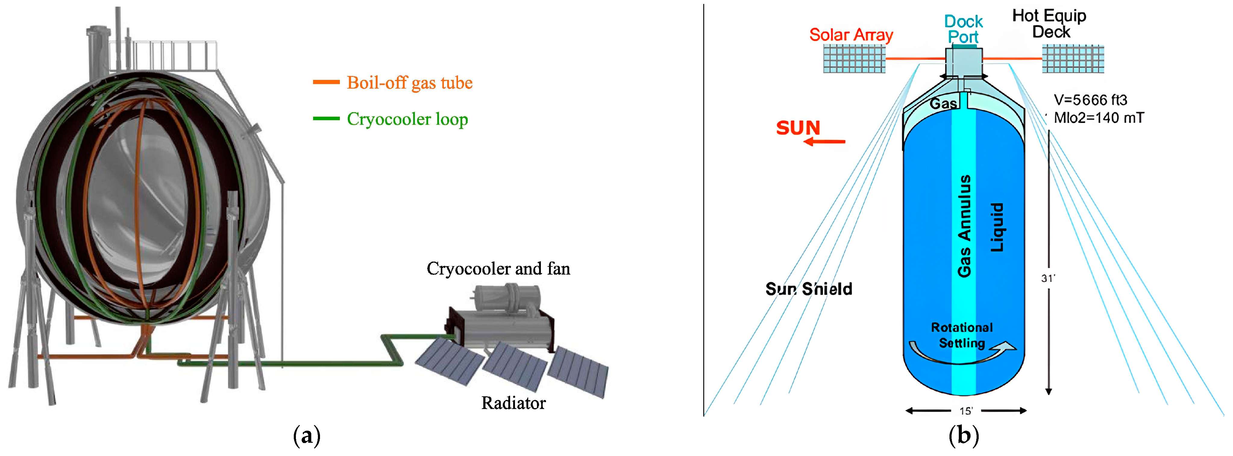
2.3.2. Illumination and Thermal Environment

Illumination conditions are key factors in the selection of research station sites and energy system designs. Elevated terrains in the lunar south pole (e.g., ridges and crater rims) can achieve up to 80% annual sunlight, making them suitable for PV generation which can support hydrogen production and liquefaction. However, the high temperatures in these areas limit their suitability for low-temperature LH2 storage. In contrast, PSRs lack sunlight but offer low temperatures and abundant water ice, making them ideal for LH2 storage. To that end, the optimal design is to deploy LH2 storage tanks in shadowed regions around illuminated zones, thereby enhancing energy utilization efficiency and reducing energy transportation consumption. If LH2 storage systems must be placed in illuminated areas (e.g., near launch zones), sunshades and lunar regolith coverage can be used to reduce heat transfer and ensure storage tank stability.
The 14-day lunar day–night cycle poses unique challenges for energy systems and thermal control design. During the lunar day, surface temperatures can reach up to 120 °C, necessitating active cooling systems powered by PV arrays combined with energy storage technologies to stabilize storage tank temperatures. During the lunar night, extremely low temperatures (−180 °C) reduce cooling requirements but still require the maintenance of LH2 temperature below 20 K. To ensure the long-term stability and efficient cooling of LH2 storage, multi-energy complementary strategies (e.g., with the use of fuel cells) should be deployed to effectively manage the source-load imbalance during the lunar day and night.

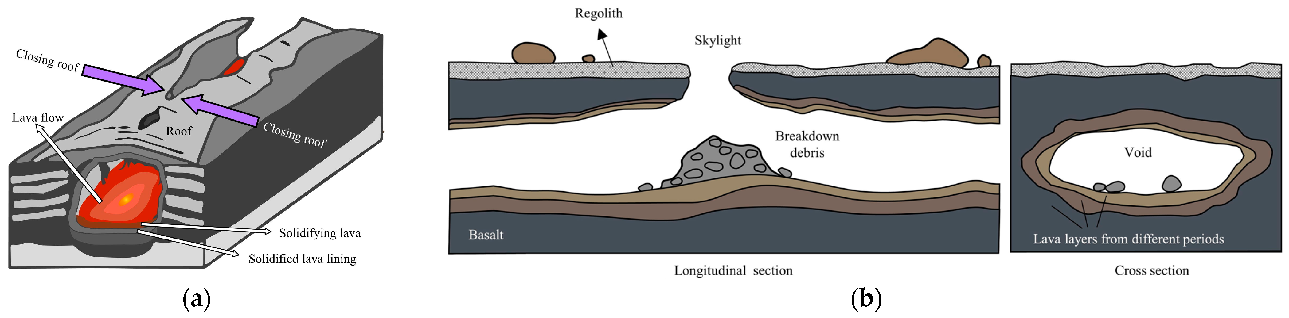
2.3.3. Dynamics and Geological Activity

Moonquakes and meteorite impacts are critical factors affecting LH2 storage systems in the low-gravity lunar environment [38]. Although moonquakes are less intense than earthquakes, their prolonged durations (e.g., “deep moonquakes” which last several minutes to hours) may have cumulative impacts on storage systems. In addition, the lack of atmosphere on the Moon allows meteoroids (ranging from dust particles to several meters in size) to directly strike the surface, potentially damaging the external structure of LH2 storage tanks or causing leakages.
As shown in Figure 3, seismic experiments and observations on the Moon provide valuable data on moonquakes and meteoroid impacts. Shockwaves from meteorite impacts or moonquakes may cause LH2 inside storage tanks to oscillate, with low-gravity conditions exacerbating liquid surface instability and gas–liquid separation. This might cause disruptions to the pressure balance within the tank and accelerate hydrogen evaporation. To mitigate these risks, LH2 storage system designs must incorporate impact-resistant and anti-vibration capabilities. In addition to using shock-absorbing structural materials, tanks can be partially buried beneath lunar regolith or shielded with artificial barriers to reduce micrometeorite damages. Furthermore, passive fluid control structures such as internal baffles, anti-sloshing partitions, or optimized tank geometries should be integrated to suppress LH2 surface oscillations. Moreover, precise liquid level control and gas recovery systems are essential to suppress fluid dynamic effects, ensuring the long-term stable storage of LH2 under low-gravity conditions.

2.3.4. Operating Environment and Orbital Characteristics

Charged lunar dust is another critical factor affecting LH2 storage systems. Lunar dust charged by solar wind and sunlight tends to adhere to equipment surfaces, reducing the efficiency of solar panel arrays and potentially impairing the thermal management and sealing performance of LH2 storage systems. Dust accumulation can also interfere with the normal operation of electronic equipment. Effective dust mitigation measures, such as anti-adhesion coatings and electromagnetic cleaning technologies, are required to minimize dust accumulation and ensure the efficient operation and long-term stability of LH2 storage systems and PV arrays.
The Moon’s synchronous rotation along its orbit around Earth (i.e., tidal locking) ensures that the same side always faces the Earth, preventing direct communication with the far side. In addition, the complex lunar surface topography including impact craters and ridges can obstruct signals, leading to significant attenuation or loss. This will cause disruptions to real-time monitoring and regulation of LH2 storage systems, threatening their stability and safety.
As shown in Figure 4, The 5.15° inclination of the Moon relative to the Earth’s orbital plane together with the 1.55° tilt of the equatorial plane relative to the Sun [39] provide unique advantages for lunar radiation cooling technologies. The fixed solar incidence angle enables radiation coolers to achieve stable thermal management across the lunar daytime and night. This allows LH2 storage tanks to maintain low temperatures without the need for complex and energy-intensive cooling systems, significantly improving storage efficiency and reducing energy consumption [40].

2.4. Deployment Strategies for Lunar LH2 Storage

The siting of LH2 storage tanks on the Moon is a critical aspect of lunar energy system planning. Different deployment strategies directly influence storage efficiency and mission feasibility. During the initial mission phase, spent rocket stages can be retrofitted as temporary LH2 storage tanks to reduce construction costs and meet immediate mission requirements. This approach leverages existing resources for rapid deployment, although it is limited by the thermal management capacity and long-term structural stability of the rocket stages, making it suitable only for short-term missions or early-stage applications [41].
With missions turning into long-term planning, PSRs become the preferred siting options [20]. The extremely low environmental temperatures (i.e., as low as 40 K) provide natural conditions for low-temperature LH2 storage, significantly reducing cooling demands and boil-off losses. However, the complex terrain and lack of sunlight in these regions pose challenges for equipment maintenance and energy supply. To address these challenges, wireless power transfer technologies can be used to deliver electricity to the storage tanks at PSRs from sunlit areas. Nevertheless, the high infrastructure costs necessitate a thorough evaluation of mission requirements and technical feasibility.
On the other hand, sunlit regions could be also suitable for the placement of storage tanks so as to support refueling and related missions [42]. These areas provide ample energy for hydrogen production, liquefaction, and transportation, though their high-temperature environment presents challenges for maintaining low-temperature LH2 storage. In such cases, storage tanks can be partially or fully buried underground to take advantage of the low thermal conductivity of lunar regolith. Alternatively, storage tanks can be insulated with protective structures to mitigate temperature fluctuations. This balancing approach ensures energy acquisition and temperature stability, making sunlit regions ideal for storage tanks near launch areas.
As shown in Figure 5, architectural design and modular construction for lunar infrastructure provide solutions for the efficient deployment of LH2 storage tanks. The Xuanwu lunar structure and the planetary LEGO brick design illustrate potential approaches to constructing modular, adaptable storage systems that can be deployed across the lunar surface.
Lunar lava tubes or subsurface caves offer an alternative option for LH2 storage [45]. The stable temperatures within these structures together with reduced diurnal temperature variations and radiation exposure create favorable conditions for low-temperature hydrogen storage [46,47]. Furthermore, lava tubes can protect storage tanks against moonquakes and meteoroid impacts [48,49]. However, their limited distribution and remote or complex locations may increase the difficulty in propellant transportation [50]. Figure 6 illustrates the formation and morphology of lava tubes. The placement of LH2 storage within lava tubes is more suitable for long-term missions as a supplementary strategy rather than a primary choice for early missions.
Orbital propellant depots present a forward-looking option for hydrogen storage [52]. Storing LH2 at the Earth–Moon Lagrange Point 1 (L1) offers strategic advantages [53]. Compared to the complex thermal environment on the lunar surface, the stable temperature conditions at L1 significantly reduce boil-off losses and create an efficient refueling hub for deep-space missions [54]. As shown in Figure 7, lunar cryogenic storage and orbital fluid management systems provide viable solutions for efficiently storing and managing hydrogen in space. The L1 storage option not only lowers the energy costs of transporting propellants from the Earth but also supports various cislunar orbital missions, solidifying the critical role of hydrogen in lunar research stations and deep-space exploration [55].
In summary, the siting of lunar LH2 storage tanks requires a comprehensive evaluation of mission phases, terrain conditions, and technical requirements [58]. From the retrofitting of spent rocket stages during initial phases to the deployment at PSRs and sunlit regions for surface missions, and ultimately to orbital propellant depots for long-term planning, these strategies complement one another across different mission stages [59,60]. Future deployment plans must optimize designs to deal with the complexity of the lunar environment, ensuring the long-term stability of LH2 storage and meeting the diverse requirements of lunar research stations [61,62].

3. Passive Thermal Protection Technologies for LH2 Storage Systems

Passive thermal protection in cryogenic systems relies on advanced insulation techniques for heat transfer minimization or self-regulation methods for heat dissipation.

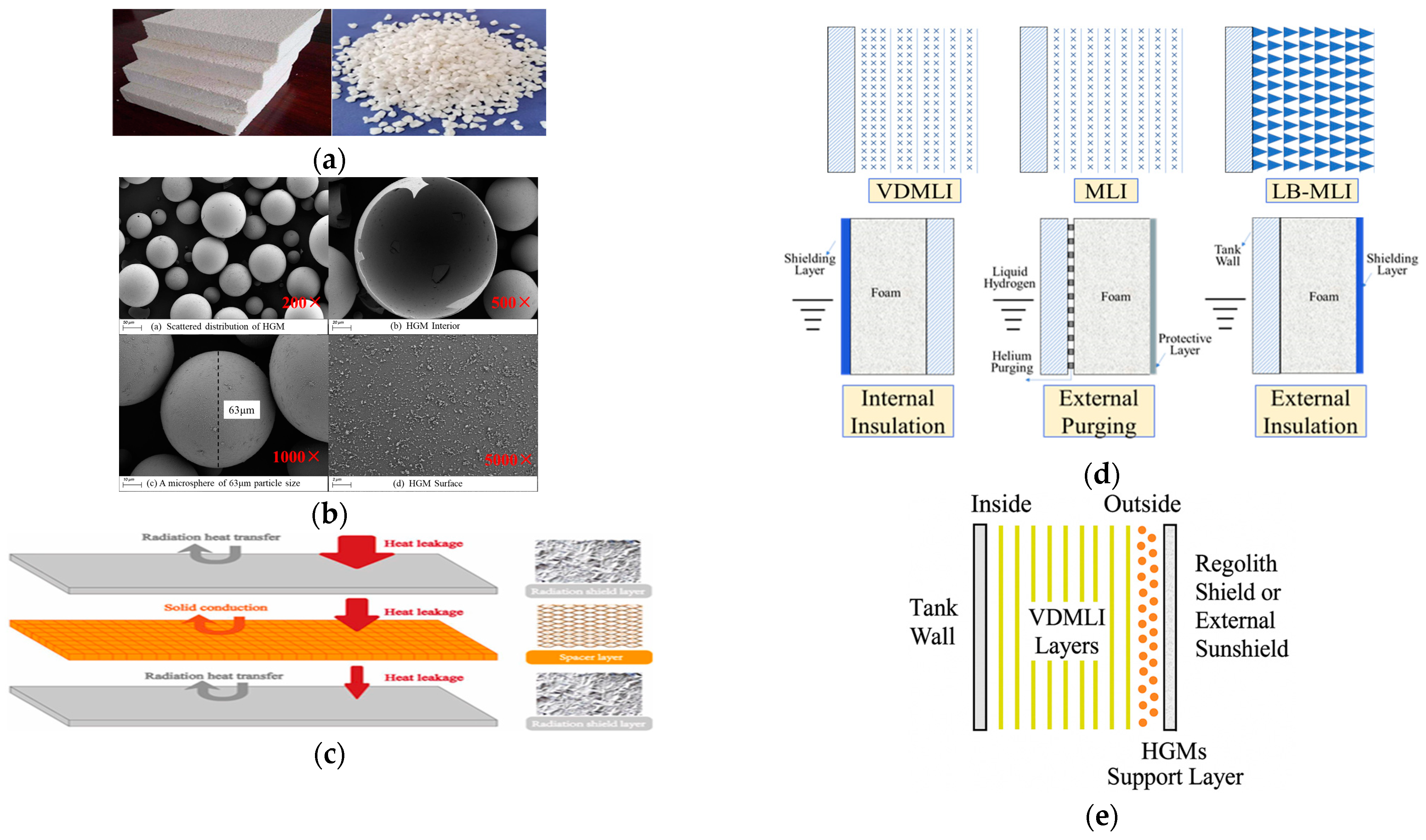
3.1. Advanced Insulation Material Technologies

External insulation is the most widely adopted strategy for cryogenic storage tanks, which utilizes advanced materials and structural designs to minimize heat transfer. Commonly used materials include porous foams, spray-applied insulation, fiber-reinforced plastics, aerogels, glass bubbles, perlite, and hollow glass microspheres (HGMs). Advanced multilayer insulation (MLI) and variable-density multilayer insulation (VDMLI) can further enhance performance in high-vacuum environments [63]. MLI typically consists of reflective shields and spacers [64,65,66,67]. Reflective shield materials are mainly categorized into low-emissivity metal foils (e.g., aluminum foil, copper foil, gold foil, nickel foil, molybdenum foil, stainless steel foil) and plastic films coated with metal layers (e.g., polyester or polyimide films coated with gold or aluminum). From a range of low-emissivity metal foils, aluminum foils and aluminized polyester films are the most commonly used. Aluminum foils provide better insulation performance but have lower tear strength, requiring thicker materials for practical use. In contrast, aluminized polyester films offer higher strength and are more suitable for lower-temperature environments. Spacer materials include loose fibers, fiber cloth, mesh fabrics, and foam plastics. Instead of traditional spacers, discrete polymer spacers are incorporated into the Load-Bearing Multilayer Insulation (LBMLI) to support the structure of insulation shell, thereby reducing thermal leakage. In some particular cases, crinkled or embossed metallized plastic films are used without spacers to reduce contact heat transfer. Beyond material selection, insulation performance is closely related to the number of reflective shield layers, spacer thickness, layer overlap configurations, vacuum degrees within material gaps, and the type of filler gases present.
MLI demonstrates dual thermal properties, with radiative or solid conductive heat transfer dominating at the high- or low-temperature boundary, respectively. To optimize the MLI performance, NASA introduced the VDMLI structure [68], which uses higher-density layers on the high-temperature side to reduce radiative heat transfer and lower-density layers on the low-temperature side to minimize solid conductive heat transfer [69]. This design is divided into three sections, i.e., low-density, medium-density, and high-density regions. The primary research focus of VDMLI is to determine the optimal layer density distribution that achieves the best insulation performance with minimal mass [70,71]. Despite their excellent thermal insulation performance, both MLI and VDMLI are highly sensitive to vacuum conditions. Any vacuum disruption can significantly degrade performance, necessitating their combination with foam or HGMs for reliability enhancement [71,72,73].
Foam insulation is well-suited for non-vacuum environments but performs poorly under high-vacuum conditions. Perlite, though being cost-effective, is hindered by high water absorption, compaction, and settling, which degrade its long-term performance and increase maintenance requirements. In contrast, HGMs exhibit superior thermal insulation, lower water absorption, and excellent vacuum stability, making them an ideal alternative to perlite in lunar applications.
In summary, each insulation material technology has its advantages and limitations. For lunar cryogenic systems, a combination of multiple insulation material techniques such as MLI, VDMLI, and HGMs is essential to achieve optimal performance. Such integrated designs can effectively address the unique challenges posed by the Moon’s vacuum, low gravity, and extreme temperature cycles. Figure 8 shows the advanced insulation materials and structures of lunar cryogenic systems including scanning electron microscopy images of HGMs, foam and perlite insulation materials, arrangements and working principles of MLI, and structural comparisons of multilayer systems. Furthermore, an integrated schematic of a lunar cryogenic tank insulation configuration is proposed, as shown in Figure 8e.

3.2. Radiation Shielding

The external heat flux on cryogenic propellants stored on the Moon primarily originates from solar radiation, lunar albedo, and Earth’s infrared radiation. In 2007, the United Launch Alliance (ULA) designed a sunshield system for the Centaur upper stage and conducted preliminary thermodynamic calculations for the system [76]. This sunshield system consists of five components, with its position being controlled by the injection of gas into vertical and horizontal arms. The required gas is sourced from the propellant tank. For in-orbit applications, NASA utilized sunshield technologies in the Titan Explorer mission to mitigate the influences of space heat radiations on cryogenic storage tanks [77].
On the lunar surface, radiation shielding can be achieved through various structural forms and materials, including shells, arches, or layered protective systems [78]. The use of locally available regolith remains a practical solution, which can effectively reduce radiation heat flux, mitigate micrometeorite impacts, and minimize heat transfer due to its low thermal conductivity [79]. As shown in Figure 9, radiation shielding strategies, such as shell structures, are essential for protecting cryogenic propellants on the Moon’s surface. In addition, advanced materials and engineered structures can be integrated to enhance thermal performance and structural stability [80]. For instance, a protective layer made from a combination of regolith and lightweight insulation materials could provide superior shielding [81]. While regolith-based shielding reduces reliance on imported materials and lowers construction costs, its utilization requires specialized equipment for excavation, transportation and application. When combined with advanced insulation systems, such solutions offer effective and sustainable strategies for cryogenic propellant storage under the Moon’s extreme environmental conditions.

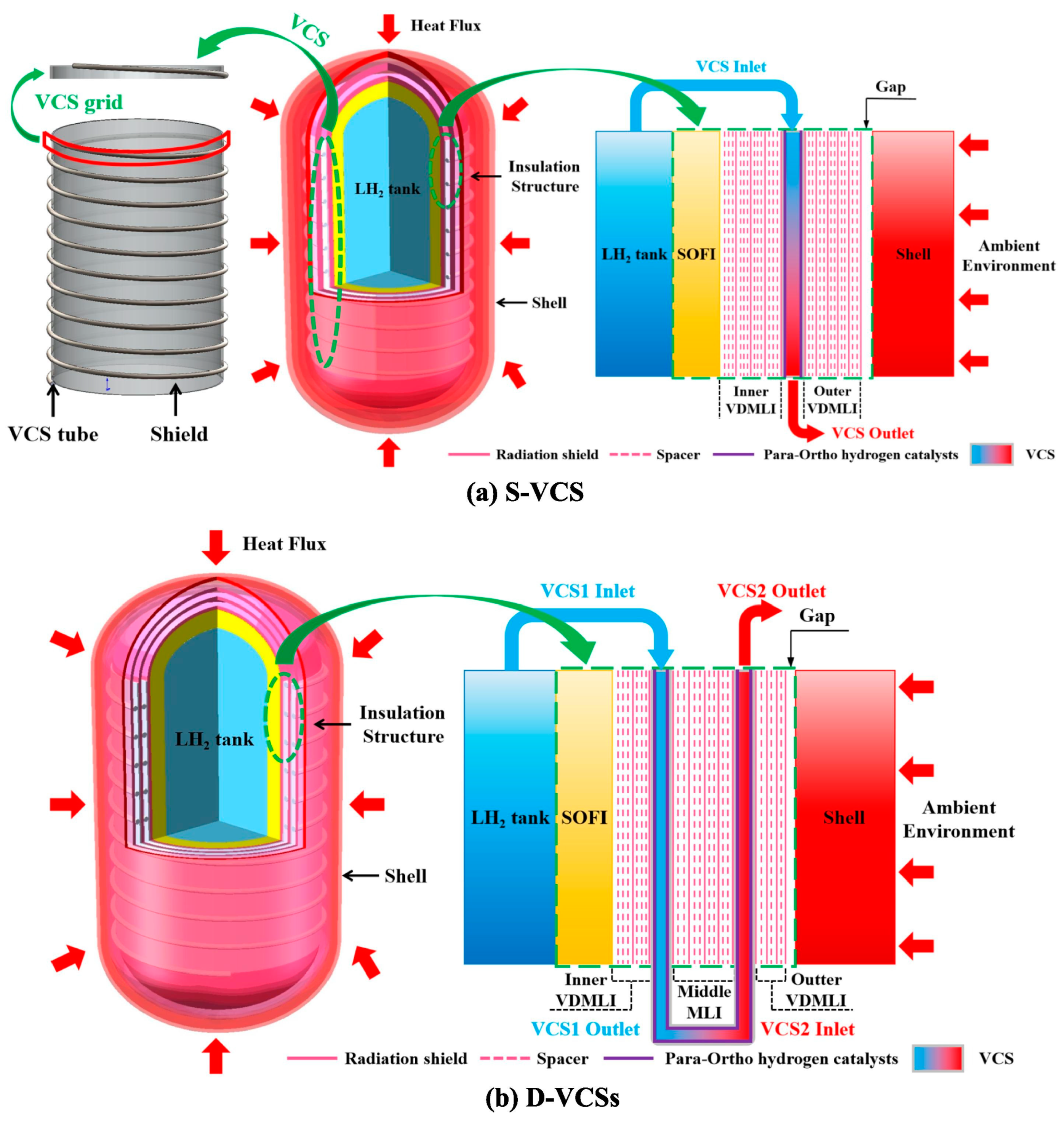
3.3. Vapor-Cooled Shield (VCS) Technology

The working principle of the VCS technology involves the recovery of the cooling energy of evaporated hydrogen for the insulation layer cooling. When the tank reaches its pressure limit, even though the vented cryogenic hydrogen is slightly above its saturation temperature, it can still provide sensible heat for cooling. Given hydrogen has a high ratio of sensible heat to latent heat, VCS demonstrates a significant efficiency in reducing LH2 evaporation rates. As shown in Figure 10, the comparison of different VCS configurations, including S-VCS and D-VCS, highlights the various approaches to optimizing cooling efficiency and minimizing evaporation losses. Current research on VCS mainly deals with its integration with composite insulation systems [83,84,85], with a particular focus on examining the optimal number, configuration, and placement of VCS layers [86,87,88].
Considering that LH2 and LO2 are often stored together, VCS can be classified into two types based on the cooling method, i.e., independent VCS and integrated VCS. Independent VCS cools each tank using its own internal vapor, with the heated vapor being directed to fuel cells for electricity generation. Integrated VCS first uses hydrogen vapor to cool the LH2 tank followed by the LO2 tank, and then releases the heated hydrogen vapor into external environment. Each approach has its own advantages and disadvantages. Independent VCS maximizes vapor utilization at 100%, though the efficiency and cost-effectiveness of the fuel cells require further evaluation. In contrast, integrated VCS features a simpler structure and enables zero boil-off in the LO2 tank, though the released hydrogen vapor is not fully utilized.

3.4. Para-Hydrogen Refrigeration Technology

As a diatomic molecule, hydrogen exists in the forms of ortho- and para-hydrogen, depending on the spin orientation of the two hydrogen atoms. Ortho- and para-hydrogen exhibit different quantum characteristics. The former has symmetric spin and antisymmetric rotational states, while the latter shows the opposite characteristics. Hydrogen typically exists as a mixture of ortho- and para-hydrogen, with the ratio being temperature-dependent. At temperatures above room temperature, hydrogen (known as standard hydrogen) consists of 75% ortho-hydrogen and 25% para-hydrogen. Under one atmosphere, the equilibrium concentration of para-hydrogen in LH2 is 99.82%. The ortho-to-para conversion in gaseous hydrogen requires a catalyst, whereas the conversion in LH2 occurs spontaneously but at a slow rate [90]. The ortho-to-para conversion is an endothermic reaction where the amount of heat absorption depends on the temperature. It was found in [91] that para-to-ortho hydrogen conversion mainly follows three thermodynamic pathways: isothermal, adiabatic, and continuous conversion. Among the three pathways, continuous conversion conducted within a thermal shielding structure was shown to more efficiently utilize the latent cold energy released during spin isomer transition, making it a promising approach to enhancing insulation performance in space-based hydrogen systems [91]. Relevant research [92,93] found that utilizing the vaporized para-hydrogen in LH2 storage tanks for conversion and recovering the cooling energy can re-liquefy 40% of the vaporized hydrogen, which can be used for the precooling in the liquefaction process. An experiment conducted by Washington State University [94] which combined vapor screens with para-to-ortho conversion demonstrated a 50% improvement in refrigeration capacity through the conversion process. The spatial positioning of the converter and VCS has also been optimized by placing the converter near the middle of the VCS channel and positioning the VCS itself closer to the cold boundary, which improved conversion effectiveness and overall insulation performance. These findings highlight the strong coupling between para-hydrogen conversion and VCS technologies in the enhancement of thermal efficiency for LH2 storage on the Moon.

3.5. Passive Venting Technology

Passive venting technologies involve the automatic release of vapor when the tank pressure exceeds its rated pressure. They can be categorized into non-bottom-venting and bottom-venting approaches. The former is prone to expelling liquid propellant out of the tank under microgravity conditions. Regardless of the method, passive venting increases the loss of cryogenic propellant.
In summary, the classification of passive thermal protection technologies into universal, mobile, and stationary categories highlights their respective strengths and limitations under different lunar storage scenarios. Universal technologies, such as advanced insulation materials and radiation shielding, provide a versatile foundation for both mobile and stationary storage. Mobile storage systems rely on specialized techniques, including structural support and attitude control, to cope with the challenges of motion and uneven thermal distribution. On the other hand, stationary solutions deal with the unique requirements of the lunar surface environment through vapor-cooled shielding and para-hydrogen refrigeration systems. These classifications not only facilitate the selection of appropriate technologies for specific applications but also provide valuable insights into future efforts on optimization and integration of thermal protection technologies.

4. Active Cooling Technologies

The long-term storage of cryogenic propellants inevitably faces the challenge of heat leakage from the external environment, which increases the propellant temperature and causes propellant losses through vaporization. To achieve lossless long-term storage of cryogenic propellants, active cooling technologies are essential approaches which involve refrigeration systems powered by external energy sources to lower or maintain the temperature of cryogenic systems.

4.1. Cryogenic Fluid Mixing Technology

In low-gravity environments, heat transfer within fluid regions is primarily governed by micro-convection and conduction, which are relatively slow processes. This slow transfer rate can result in radial temperature gradients within the propellant tank. Thermal stratification leads to uneven energy distribution within the propellant, increasing the vaporization rate in localized liquid regions. The generated gas causes a rapid rise in tank pressure, affecting the structural integrity of the tank and the efficient utilization of the propellant.
Cryogenic fluid mixing technology works by extracting cryogenic liquid from the tank and re-injecting it through nozzles or jets, driving fluid motion to effectively disrupt thermal stratification. This process maximizes the utilization of the fluid’s cold storage capacity, reducing evaporation losses and improving the diffusion of cooling energy [95,96,97]. Early research conducted by the Glenn Research Center (GRC) [98] on cryogenic fluid mixing employed axial jet devices to mix the colder liquid at the bottom of the tank with the warmer fluid near the tank walls and the gas–liquid interface. The study demonstrated that this technology could significantly reduce thermal stratification and pressure within the tank, thereby mitigating uneven energy distribution.
As shown in Figure 11, the flow pattern and phenomena within a mixing tank further illustrate how cryogenic fluid mixing disrupts thermal stratification, improving the efficiency of cryogenic fluid storage systems.
While fluid mixing technology can delay the vaporization of propellants, it does not eliminate the source of heat. Additionally, some of the power consumed by the mixing device is converted into heat that is transferred to the cryogenic fluid. Therefore, this technology has inherent limitations and is often combined with other techniques to achieve optimal results.

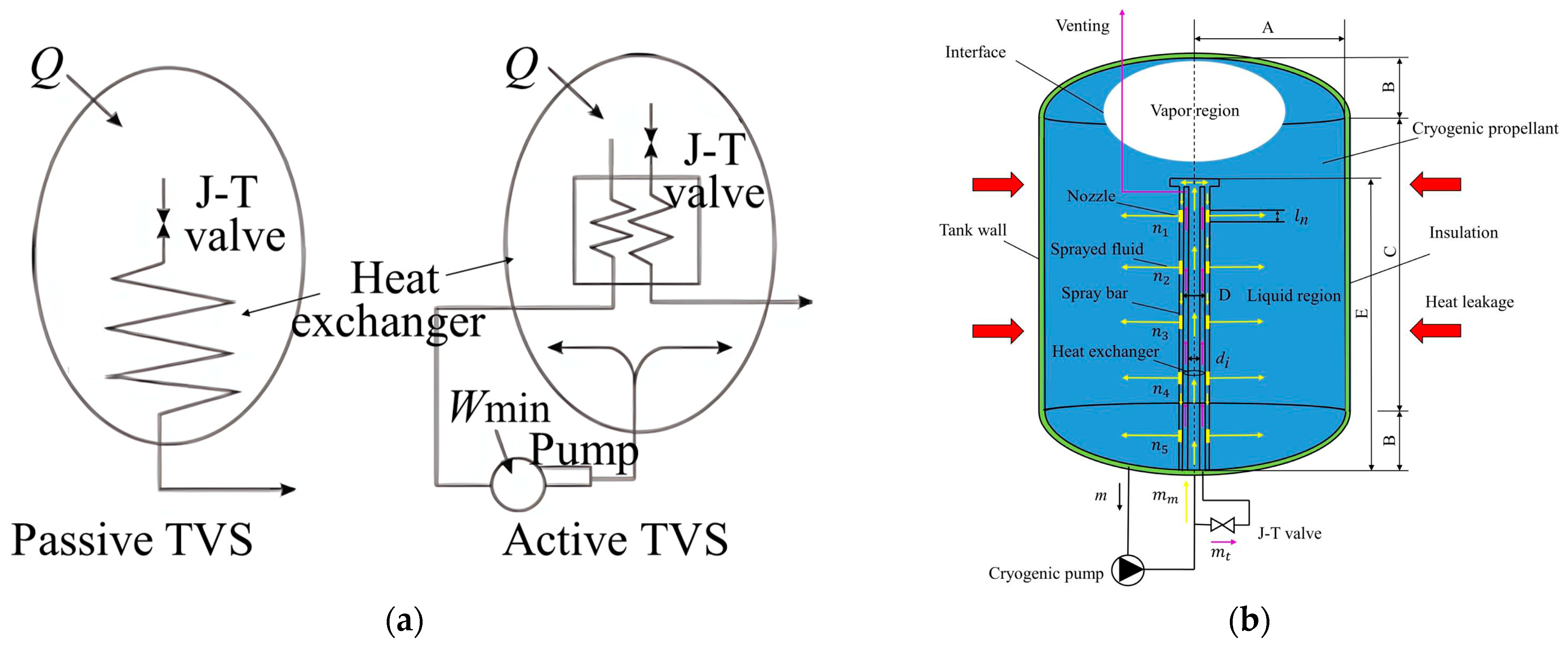
4.2. Thermodynamic Vent System (TVS)

A TVS operates by extracting a portion of fluid from the storage tank, which is expanded through a Joule–Thomson (J-T) valve into a low-temperature, low-pressure fluid [68,99,100,101]. This fluid absorbs heat from the propellant within the tank through a heat exchanger, and then evaporates into gas and vents into external environment. The majority of the remaining LH2 in the tank is pumped into the outer tube of the heat exchanger where it absorbs the cooling energy from the inner tube before being reintroduced into the storage tank, effectively lowering the LH2 temperature [102].
Figure 12 illustrates two TVS types. Passive TVS generally consists of a J-T valve and heat exchanger which are typically installed inside the tank. Active TVS builds upon the passive system and adds circulation pipelines and cryogenic pumps, which are installed outside the tank to facilitate maintenance and prevent heat generated by the equipment from being transferred into the tank. Furthermore, the low-temperature fluid after throttle is sprayed radially via a spray bar which traverses the gas cushion and liquid phase. Regardless of the position of the gas–liquid interface, the spray bar of TVS can effectively eliminate thermal stratification within the storage tank.

4.3. Cryocooler Technology

Cryocoolers, such as the Gifford–McMahon (G-M) cryocooler, Stirling cryocooler and pulse tube cryocooler, are commonly used to cool propellants and reduce their temperature [104,105,106]. Existing flight-proven cryocoolers provide approximately 1 W cooling power at LH2 temperatures, with a 6–8 K temperature gradient between the cryocooler cold head and the fluid. This results in low efficiency and high energy consumption for heat transfer [107,108]. To that end, the application of cryocoolers requires storage tanks to have excellent insulation properties to ensure that external heat leakage matches the cryocooler’s cooling capacity.

4.3.1. Typical Cryocooler Configurations

Internal condenser design: This configuration connects the condenser directly to the cryocooler cold head and places it inside the tank to carry heat away from the gas [109]. However, since the condenser is typically located at the top of the tank, it cannot cover the entire tank and requires additional structures to increase the area of heat exchange. NASA GRC [110] verified the feasibility of combining internal condensers with copper plates for zero-boil-off storage.
Spray bar and circulation pump design: This method employs a circulation pump to extract low-temperature liquid, which is cooled via the cryocooler cold head and then reintroduced into the tank through a heat exchanger spray nozzle. The low-temperature liquid interacts with the tank fluid via convective heat exchange to reduce heat within the tank and maintain the pressure, which mitigates the thermal stratification in LH2. This design was employed in the zero-boil-off experiment carried out by Hedayat et al. [111], which used a cryocooler with a capacity of 30 W at 20 K. Zero-boil-off LH2 storage was achieved at fill levels of 20%, 50%, and 95%. Hastings et al. [112] also successfully implemented this configuration in the zero-boil-off storage experiments for LH2 and LO2.
Cryogenic heat pipe with heat exchanger design: This configuration integrates cryogenic heat pipes and heat exchangers deep within the tank, forming submerged mixed-flow pumps. The cryocooler’s cooling power is transmitted into the tank through the heat pipe, while spray nozzles drive tank fluids toward the cold end of the heat pipe, transferring cooling capacity into the tank. NASA GRC’s Plachta [113] conducted zero-boil-off experiments for liquid nitrogen using this design, successfully achieving zero evaporation for liquid nitrogen. However, a 6.9 K temperature gradient between the cryogenic system and the liquid was observed and additional heat was introduced by the use of pumps, presenting limitations compared to internal condensers.

4.3.2. Large Area Cooling Technology

Early methods for zero-boil-off storage relied on transferring cooling power to tank fluids for temperature and pressure regulation. Large-area cooling (or Board-Area-Cooled, BAC) technology was proposed in 2007 by NASA GRC [114,115,116], which uses a large-area gas-cooled screen to cover the exterior of the cryogenic tank to neutralize heat leakage. The system comprises a circulation pump, cryocooler, and a large area cooling screen, forming a closed loop. The circulating gas, typically helium, is cooled by the cryocooler before entering the gas-cooled screen for heat neutralization. The gas is then returned to the cryocooler by the circulation pump. The cooling screen is uniformly distributed across the tank, eliminating the effects of thermal stratification and ensuring a uniform temperature distribution.
As shown in Figure 13, the large-area cooling technology, which uses a gas-cooled screen to neutralize heat leakage, is an effective method for ensuring zero-boil-off storage by minimizing evaporation losses. This approach significantly improves the thermal efficiency of cryogenic storage systems, making it ideal for long-term storage of cryogenic propellants like LH2.
NASA GRC [117] employed the large-area cooling approach in zero-boil-off storage experiments, utilizing a reverse Brayton cycle cryocooler with a capacity of 15 W at 90 K and neon as the working gas. The experiment achieved zero boil-off for LO2 but failed to realize zero boil-off for LH2 due to cryocooler limitations, though evaporation losses were reduced by 60%. In 2017, NASA successfully tested the Integrated Refrigeration and Storage (IRAS) system [118,119], featuring Linde Corporation’s LR1620 ammonia cryocooler with a cooling capacity of 390 W at 20 K. This system achieved zero-boil-off storage for LH2, marking a significant advancement in cryogenic storage technologies.

5. Advances in Boil-Off Hydrogen (BOH) Recovery Technologies

In the context of extremely scarce energy resources on the Moon, minimizing the occurrence of BOH is a critical challenge in LH2 storage. High-performance insulation technologies can significantly reduce heat transfer, though they cannot eliminate BOH emissions during prolonged storage [103,120,121]. The combination of active cooling and MLI in zero-boil-off (ZBO) systems presents a potential solution. Nevertheless, ZBO systems face challenges such as complex designs, high energy consumption, and limitations posed by the Moon’s prolonged day–night cycle and intermittent electricity supply. It is difficult for refrigeration systems to operate continuously during the 14-Earth-day-long lunar night. Even intermittent ZBO methods might still result in venting losses and safety risks. Furthermore, the high manufacturing and maintenance costs of ZBO systems restrict their practicality. To that end, the development of more economical, efficient, and stable BOH control and recovery technologies tailored to lunar environments remains a key focus for future research.
On Earth, BOH recovery technologies for hydrogen storage and transportation primarily involve reliquefaction and compression methods, which have been both widely studied and applied. Reliquefaction which cools the BOH back into LH2 is typically used in large-scale hydrogen storage and transportation systems. While reliquefaction offers a high energy recovery efficiency, it imposes stringent requirements on facility space, cooling capacity and energy supply, largely increasing capital and operational expenditures (CAPEX and OPEX). Compression recovery is a more flexible alternative, especially suitable for converting BOH into high-pressure gaseous hydrogen for use in hydrogen refueling stations or buffer storage scenarios. Despite its adaptability, compression recovery entails significant energy consumption and cost management challenges.
Although these technologies have achieved notable success in terrestrial applications [122], the Moon’s unique and extreme conditions such as large temperature variations between day and night, intermittent energy availability, and constraints on infrastructure pose new challenges for their implementation. Effective BOH recovery on the Moon is crucial not only for improving LH2 storage efficiency and safety but also for supporting the sustainability of the lunar base’s energy systems. Therefore, it is important to assess the strengths and limitations of terrestrial reliquefaction and compression recovery technologies and tailor them to the Moon’s specific requirements. This section summarizes existing terrestrial BOH technologies and explores their potential applicability and modifications for lunar environments.

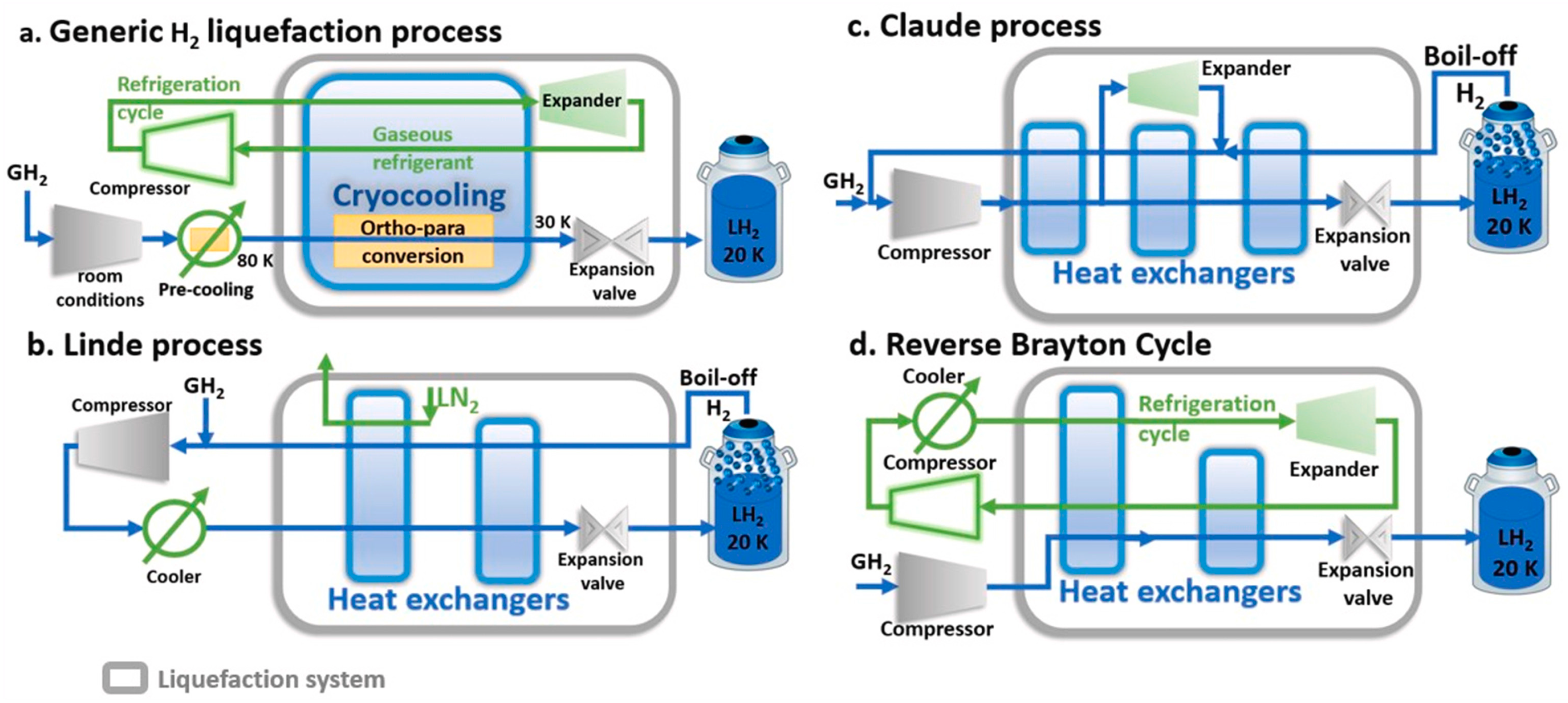
5.1. Hydrogen Reliquefaction

Liquefaction is an energy-intensive cooling process [123], with the theoretical energy requirement for hydrogen liquefaction at approximately 3.92 kWh/kg of LH2 [124]. This is significantly higher than the energy requirement of 0.31 kWh/kg for liquefied natural gas (LNG). The liquefaction process typically involves four stages: compression, precooling, cryogenic cooling, and Joule–Thomson (J-T) expansion liquefaction [125].
Current hydrogen liquefaction technologies primarily include the Linde process, Claude process, and reverse Brayton cycle. The Linde process utilizes liquid nitrogen to precool hydrogen to below its J-T inversion temperature (approximately 200 K), followed by J-T valve expansion to achieve liquefaction [126]. The operating pressure depends on the specific design, and the Linde process was once found to achieve the best thermodynamic performance at around 13 MPa [99]. On the other hand, the Claude process uses an expansion turbine to provide additional cooling energy, reducing reliance on liquid nitrogen and improving energy efficiency [100]. The reverse Brayton cycle which usually employs helium as refrigerant is widely used in small- and medium-scale liquefaction systems. Although its efficiency is slightly lower than the Claude process, the reverse Brayton cycle can operate at lower pressure levels, offering improved safety and reliability [101]. As shown in Figure 14, the simplified flow diagrams of the generic hydrogen liquefaction system and the three primary processes (Linde, Claude, and reverse Brayton cycle) illustrate the operational stages and technological differences.
The performance of liquefaction technologies is typically evaluated by the specific energy consumption (SEC) and exergy efficiency (EXE). Existing research has revealed significant differences in SEC and EXE between various processes. For example, the mixed-refrigerant precooled Brayton cycle (as in the IDEALHY project) achieved an SEC of 6.7 kWh/kg of LH2 [128], while the traditional Linde–Hampson process exhibited an SEC of 7.69 kWh/kg of LH2 [129]. The four-stage cascaded Claude process with mixed-refrigerant precooling demonstrated an even higher efficiency, achieving an SEC of 5.91 kWh/kg of LH2 and an EXE of approximately 39% [130]. Furthermore, systems using helium-based reverse Brayton cycles could reach EXE values as high as 49.41% [131]. In industrial applications, the four-stage helium cascaded Brayton cycle was designed and achieved an outstanding SEC of 5 kWh/kg of LH2 and an EXE of 47.73%, highlighting the immense potential for liquefaction technology optimization [132].
Although SEC values were significantly reduced in some experimental systems, the energy efficiency of the liquefaction process remains constrained by various factors, including the choice of refrigeration cycles, equipment design optimization, and the balance between energy consumption and equipment costs. These performance comparisons will provide valuable insights into developing and tailoring BOH reliquefaction technologies to the lunar environments. Furthermore, BOH reliquefaction leverages the low-temperature properties of vaporized hydrogen, significantly reducing energy consumption during the precooling phase and eliminating the need for catalysts for H2 ortho-para conversion. Some reliquefaction systems which integrate reverse Brayton cycles with fuel cell power sources have demonstrated SEC values ranging from 3.3 to 10.8 kWh/kg of LH2 [133]. These findings underscore the critical role of continuous liquefaction technology optimization in supporting resource-limited energy systems of lunar bases.

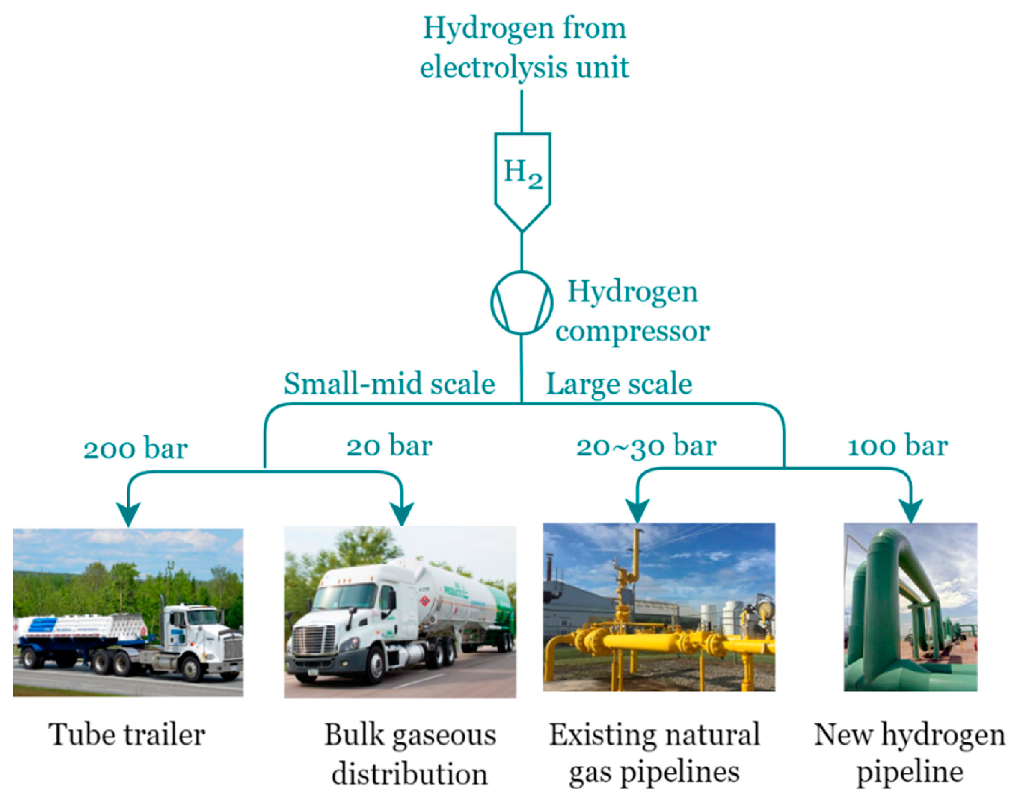
5.2. Hydrogen Recompression

Compression recovery strategies store BOH in a gaseous form or apply BOH to fuel cells, hydrogen refueling stations, etc. Hydrogen compression technologies are primarily divided into mechanical and non-mechanical methods [134]. This section systematically reviews the state-of-the-art compression methods and explores their potential applications, focusing on technological advancements. As shown in Figure 15, the pressure requirements for various methods of pressurized gaseous hydrogen distribution highlight key considerations for selecting appropriate compression technologies [135].

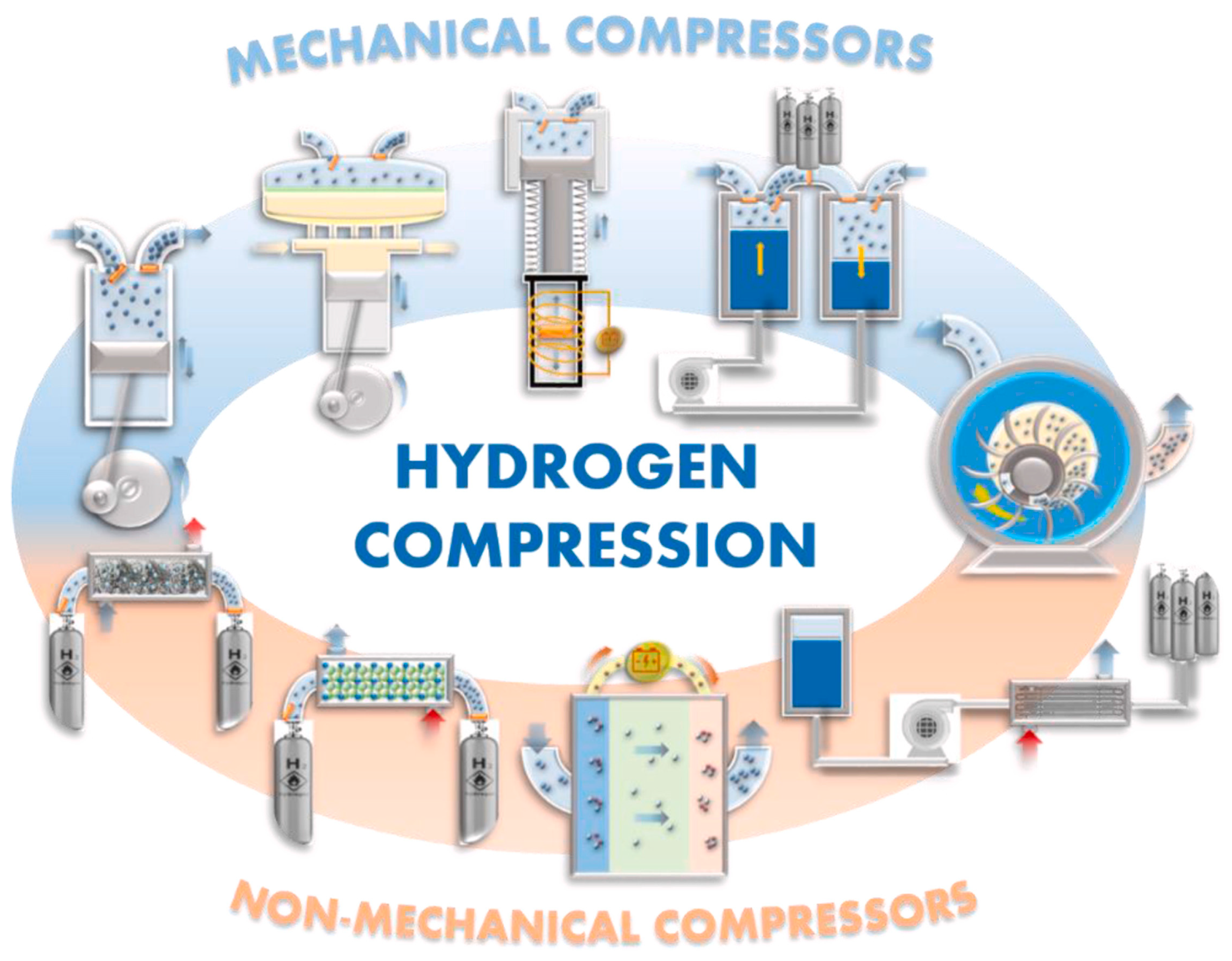
5.2.1. Mechanical Compression Technologies

Mechanical compression is currently the most widely employed method for hydrogen compression. It converts mechanical energy directly into gas energy to increase pressure. Mechanical compression technologies include reciprocating compressors, diaphragm compressors, linear compressors, and liquid piston compressors, which are favored for their efficiency and versatility on the Earth [137]. As shown in Figure 16, the schematic diagram of the compressor cross-section illustrates the design variations of these compression technologies.
Reciprocating compressors which are known for high-pressure output can achieve discharge pressures of up to 85 MPa and are widely used in terrestrial hydrogen refueling stations and industrial hydrogen production [138]. However, their reliance on numerous moving parts poses challenges in the Moon’s extremely low-temperature environment, which increases the possibility of material brittleness and lubrication failures. In addition, their design with multiple moving components results in pressure fluctuations, noise, and vibrations, which would be further magnified in the Moon’s high-vacuum environment.
Diaphragm compressors separate gas from hydraulic systems using flexible diaphragms and enable high-purity hydrogen compression [139], which is especially suitable for applications requiring stringent chemical purity [140]. However, the Moon’s low temperatures can significantly impact the mechanical strength and durability of the diaphragms. Repeated compression cycles may subject diaphragms to mechanical stress, increasing the likelihood of fatigue failure.
Linear compressors stand out for simple structure and low noises [141]. They use linear motors to drive pistons directly, minimizing the number of moving parts compared to traditional compressors [142]. This technology has been successfully applied in small-scale refrigeration and aerospace systems on the Earth. However, its present limitations in output pressure and flow capacity make it unsuitable for large-scale hydrogen compression. Moreover, the low-gravity environment on the Moon could destabilize piston movement, reducing operational reliability of linear compressors.
Liquid piston compressors pressurize gases directly through a liquid column and leverage the liquid’s high heat capacity to achieve a near-isothermal process [143], offering advantages in thermal management and efficiency [144]. However, their potential application in lunar conditions depends on further optimization of liquid sealing and low-temperature jet cooling technologies. The low-gravity environment might affect the uniform distribution of liquid flows, reducing compression efficiency.
In summary, while mechanical compression methods offer unique advantages under terrestrial conditions, they are expected to be replaced by non-mechanical compression technologies due to significant challenges in adapting to the Moon’s extreme environment.

5.2.2. Non-Mechanical Compression Technologies

Compared to mechanical compression, non-mechanical compression technologies rely on physical–chemical processes or thermodynamic principles to achieve an increase in hydrogen density without the need for complex moving parts [145]. These technologies offer advantages such as compactness, high efficiency, and no wear [146], making them theoretically well-suited for the Moon’s extreme environment. Current non-mechanical compression technologies include cryogenic compression, metal hydride compression, electrochemical compression, and adsorption-based storage, as shown in Table 1, which compares the characteristics of various commercial non-mechanical compressors.
Cryogenic compression combines the advantages of hydrogen liquefaction and compression by directly pressurizing LH2 to high-pressure states through cryogenic pumps [147]. While most LH2 pumps are designed for liquid only, Air Products has designed a compression process that uses a single pump to handle both BOH and LH2 two-phase flow, capturing BOH and delivering it to the process at high pressure without the need for pre-heating BOH [127].
Metal hydride storage increases hydrogen volumetric storage capacity through the sorption (absorption and desorption) processes of metal hydride alloys, requiring no moving parts [148]. This allows them to be powered by lunar waste heat or solar generation. However, the low thermal conductivity of metal hydride materials poses challenges for efficient operation [149]. Furthermore, material pulverization and structural expansion during cyclic operation significantly reduce system efficiency and lifespan. Moreover, the practical application of metal hydride storage on Earth is mostly limited to medium-to-low-pressure scenarios, necessitating further development to meet the requirements of high-pressure hydrogen storage on the Moon.
Electrochemical compression (EHC) operates based on proton exchange membranes (PEM), where hydrogen is catalytically oxidized at the anode into protons and electrons [150]. The protons migrate through the membrane under an applied electric field and recombine at the cathode to form compressed hydrogen. This process enables simultaneous compression and purification without mechanical components. EHC systems are compact, quiet, and highly efficient even at low voltages, making them ideal for space applications. Notably, they can compress hydrogen to over 100 MPa in a single stage and are capable of operating under isothermal conditions. However, they impose strict requirements on membrane materials. Nafion membranes which are commonly used in low-temperature EHCs require humidification to maintain conductivity [151], constraining their performance in vacuum environments like the Moon. Over-humidification can block catalytic sites, while insufficient water reduces proton transport efficiency. To address these limitations, high-temperature EHC systems using polybenzimidazole (PBI) membranes have been developed for better thermal and chemical stability, simplified water management, and enhanced tolerance to gas impurities. PBI-based EHCs can function efficiently at 120–200 °C with improved CO tolerance and catalyst activity. These systems also exhibit promise for lunar applications, though further tests under extreme lunar conditions are needed.
Adsorption-based storage technology captures hydrogen in the pores of highly porous adsorbents, such as metal–organic frameworks (MOFs), reducing hydrogen losses and improving resource utilization efficiency [152]. Studies have shown that under low-temperature conditions, MOFs can achieve hydrogen adsorption densities close to the volumetric density of LH2, with minimal adsorption energy requirements [153]. However, a large amount of material is needed to achieve sufficient adsorption capacity, which increases the weight of storage tanks and systems, thus raising the cost of lunar missions. In addition, adsorption-based storage relies on complex thermal management systems to maintain low temperatures to ensure performance [154], and requires additional heating equipment for desorption, increasing energy consumption and system complexity.
In summary, non-mechanical compression technologies remain in the development stage and have not been fully validated under extreme conditions. While they show significant potential, validation under lunar conditions is still required to address issues related to low thermal conductivity, high pressure, vacuum environments, and additional needs for cooling or heating systems which will increase energy consumption and system complexity. It is noted that sorption-based systems (such as adsorption and metal hydride storage) perform better at cryogenic temperatures than at Earth ambient conditions, making them theoretically promising for lunar applications in spite of the technical challenges such as system mass and thermal control that remain. Their practical deployment requires the addressing of challenges related to structural design, heat integration, and system scalability. In addition, except for cryogenic compression, these technologies are designed for hydrogen at ambient temperatures and do not account for BOH’s 20 K temperature. Currently, no compressors can handle such low temperatures, posing a significant challenge for their lunar applications.

6. Evaluation and Optimization of LH2 Storage Technologies

To provide insights into the feasibility of different thermal management strategies for LH2 storage under lunar environment conditions, this section performs a comprehensive evaluation of passive thermal protection technologies, active cooling technologies, and BOH recovery methods. The applicability of different technologies under the lunar environment (i.e., low temperature, low gravity, high vacuum, and prolonged lunar day–night cycle) is assessed through quantitative benchmarking and comparative scoring, based on which hybrid thermal management schemes and specific optimization pathways tailored to stationary LH2 storage at lunar bases are proposed. The proposed solutions aim to balance efficiency, reliability, and practicality of thermal management for LH2 storage, addressing both technical challenges and operational requirements in the unique lunar environment.

6.1. Technology Evaluation and Comparison

Five techno-economic metrics, including efficiency, energy consumption, complexity, cost, and applicability, are employed here to scientifically assess and compare the performance of passive thermal protection technologies, active cooling technologies, and BOH recovery technologies in the lunar environment. Rather than adopting a purely qualitative approach, an expert-informed ordinal scoring method (scores 1–5) is used here to rank the technologies across these criteria based on their performance demonstrated in literature evidence and engineering judgment. Higher scores indicate more preferable technologies (e.g., greater efficiency, lower energy use, lower cost, simpler integration, and better adaptability). It is noted that these scores reflect relative rankings rather than absolute measurements. Furthermore, to better align with the priorities of metrics for lunar operation, different weights are assigned to the five metrics, i.e., 0.25 for applicability, 0.25 for energy consumption, 0.2 for efficiency, 0.15 for complexity, and 0.15 for cost. These weights emphasize the importance of adaptability and low energy usage in the resource-constrained extreme lunar environment. Based on the weighted scores, an overall performance index is calculated and visualized in Figure 17, providing clear and intuitive comparisons across technologies. Original scores and metric-wise comparisons are summarized in Table 2.
Passive thermal protection technologies rely on natural physical characteristics to minimize heat inputs, offering low energy consumption and high stability. High-performance MLI materials which significantly reduce heat transfer are considered one of the core protection technologies for LH2 storage tanks. Even though insulation materials are relatively expensive, they are suitable for both lunar day and night environments and do not require additional electricity supply, offering near-optimal efficiency. Shielding protection which uses lunar regolith to cover storage tanks reduces solar radiations and micrometeorite impacts, offering high adaptability and low costs. However, the transportation and distribution of regolith require additional equipment support, significantly increasing the associated weight and initial construction workload. Gas-cooled shield layers which form cold shield layers by evaporated hydrogen gas are a dynamic, combined passive technology. Their primary advantages lie in the thermal conductivity reduction and lower evaporation rate of LH2, though they require integration with vapor management systems. Despite their low energy consumption and high stability, passive methods face limitations in providing sufficient thermal protection during the high-temperature lunar daytime. For instance, regolith-based shielding demands significant construction efforts and payload mass, while vapor-cooled shields depend on the availability of hydrogen and effective vapor routing. Future research is required to develop more efficient passive structures with adaptive thermal properties and reduced masses for lunar transport.
Active thermal protection technologies use external electricity supply to actively reduce heat loads, making them particularly suitable for high-temperature lunar day conditions. BAC refrigeration technologies exhibit excellent cooling capabilities under high-temperature conditions, especially during lunar days. However, their high energy consumption limit continuous operation during lunar nights, requiring additional support from fuel cells. Cryogenic heat pipes and exchangers have efficient heat transfer capabilities and can be integrated with various cooling solutions. Their low design complexity makes them suitable for long-term operation. Thermodynamic venting systems utilize the self-cooling properties of LH2 to reduce heat loads, which are well-suited for short-term pressure management. However, their efficiency is limited in scenarios requiring long-term cooling. Active cooling solutions offer better thermal control but are often constrained by energy availability, particularly during lunar nights. Cryocoolers, while effective, involve high power consumption and mechanical complexity. BAC systems are promising but require integration with reliable PV and fuel cell subsystems. Further research should address energy autonomy, miniaturization, and system reliability under lunar night–day cycles.
BOH recovery technologies are the most promising for the thermal management of LH2 storage, and reduce energy consumption and improve overall system efficiencies through resource recycling. The reliquefaction method uses refrigeration systems to recondense vaporized hydrogen into LH2, which is suitable for long-term and large-scale LH2 storage. However, this method is energy-intensive and highly complex, making it less suitable for resource-limited lunar bases. The recompression method pressurizes vaporized hydrogen for storage and/or use in fuel cells. Even though it consumes less electricity compared to reliquefaction, it still requires additional compression equipment, increasing the overall system weight. The cryogenic adsorption method employs highly porous adsorption materials (e.g., MOFs) to store vaporized hydrogen. It shows high efficiency and potential for innovation but requires advanced material technologies and further research. Although BOH recovery methods improve system efficiency by reusing evaporated hydrogen, they introduce significant design complexity and material demands. Reliquefaction is energy-intensive and difficult for large-scale applications; recompression needs high-pressure-tolerant components; and adsorption methods are still limited by material capacity and regeneration cycles. These highlight research gaps in material development, system integration strategies, and long-term reliability assessments under lunar conditions.

6.2. Feasible Scheme Design for Lunar LH2 Storage

In the extreme lunar environment, the thermal management of LH2 storage requires the integration of passive and active protection technologies to maximize energy efficiency and minimize evaporation losses. In order to provide a holistic perspective beyond individual discussions on each technology separately, a conceptual system-level blueprint is developed in Figure 18 to illustrate the integration of multiple thermal management strategies into a full-scale lunar LH2 tank system. The large diurnal temperature variation on the Moon presents significant challenges for LH2 storage. Passive protection technologies, including high-performance insulation materials, gas-cooled shielding layers, and lunar regolith covering, can effectively reduce heat conduction and heat absorption, thereby mitigating the impact of external temperature fluctuations on the storage system. However, relying solely on passive protection is insufficient to fully address the problem. During the lunar daytime, high temperatures still necessitate the use of a PV-powered BAC refrigeration system for active cooling, ensuring that the LH2 storage temperature remains within the desired range. At night, despite a significant reduction in external thermal loads, the system still requires intermittent active cooling, the managing of tank pressure, and the alleviation of heat accumulation through the release of BOH. As illustrated in Figure 18, a combined passive–active cooling approach is essential to maintain stable storage conditions throughout the lunar day–night cycle.
The multi-stage utilization strategy for BOH first cools the LO2 system, followed by the cooling of fuel cell systems, and finally, cooling of the lunar surface contact structures. As the temperature gradually increases, BOH is distributed to each system in sequence, with the warmed vapor being recovered to power the fuel cells and provide electricity for the active cooling system. The remaining vapor is stored in compressed tanks, serving as an energy reserve for nighttime operation.

7. Conclusions

This paper has compared various thermal management schemes for liquid hydrogen (LH2) storage, systematically analyzing the performance and limitations of passive and active technologies in dealing with the extreme lunar environment. Passive technologies, such as advanced insulation materials, radiation shielding, structural thermal isolation, attitude control technology, and vapor-cooled shield technology, play a critical role in reducing heat transfer and stabilizing storage temperatures. The synergistic effects of these technologies effectively counterbalance severe temperature fluctuations on the lunar surface, providing a foundational guarantee for LH2 storage. However, due to the intensive solar radiation during lunar daytime, relying solely on passive technologies is insufficient to meet the demands of thermal management under all environmental conditions. Active cooling technologies, such as cryogenic fluid mixing, thermodynamic vent systems, refrigeration technology, and large-area cooling systems, address shortcomings of passive technologies by enabling dynamic temperature control and pressure regulation, particularly demonstrating significant advantages under high thermal loads during the lunar daytime. Additionally, boil-off hydrogen (BOH) recovery technologies, including hydrogen reliquefaction, hydrogen compression, and cryogenic adsorption, further optimize system efficiencies by efficiently recovering evaporated hydrogen, reducing resource losses, and providing energy reserves for nighttime operation.
The paper has also proposed a system-level integration scheme by combining passive insulation, active cooling, and multi-stage BOH recovery into a unified framework. Such conceptual design helps bridge the gap between individual technologies and practical implementation on the lunar surface. Even though this integrated approach has demonstrated high adaptability and efficiencies, significant challenges still remain and incur the needs of (1) improving the BOH-to-energy conversion efficiency by optimizing multi-stage cooling loops; (2) developing lightweight insulation materials compatible with cryogenic and vacuum conditions; and (3) verifying long-term system reliability under simulated lunar environments. Addressing these knowledge gaps is essential for advancing LH2 storage technologies toward practical deployment on the Moon. To that end, future optimization directions include an increased BOH utilization efficiency by improving design of BOH-based fuel cell cooling systems to reduce heat loss and enhance cooling efficiency. Additionally, the development of lightweight insulation materials compatible with low-temperature and high-vacuum conditions will help reduce system weight and simplify structural complexity. To validate the long-term operational reliability of this scheme under actual lunar conditions, comprehensive simulated experiments must be conducted to assess the performance of LH2 storage systems in the context of extreme temperatures, vacuum conditions, and low gravity. Continuous exploration in these areas will further enhance the overall feasibility of the scheme and provide more robust solutions to lunar LH2 storage and BOH recovery system designs.

Author Contributions

Conceptualization, T.F. and K.S.; methodology, J.L. and J.X.; formal analysis, J.L., H.L. and F.F.; investigation, J.L., J.M. and F.F.; resources, K.S.; data curation, J.L.; writing—original draft preparation, J.L. and F.F.; writing—review and editing, T.F., C.S., J.J., R.X., W.Y. and K.S.; visualization, J.L.; supervision, T.F., C.S., J.J., R.X., W.Y. and K.S.; project administration, T.F. and K.S.; funding acquisition, T.F. and K.S. All authors have read and agreed to the published version of the manuscript.

Funding

This research was funded by the National Natural Science Foundation of China Key Project (52238002).

Data Availability Statement

Data sharing is not applicable.

Conflicts of Interest

The authors declare no conflicts of interest.

References

  1. Saha, D.; Bazmohammadi, N.; Raya-Armenta, J.M.; Bintoudi, A.D.; Lashab, A.; Vasquez, J.C.; Guerrero, J.M. Space microgrids for future manned lunar bases: A review. IEEE Open Access J. Power Energy 2021, 8, 570–583. [Google Scholar] [CrossRef]
  2. Benaroya, H.; Bernold, L. Engineering of lunar bases. Acta Astronaut. 2008, 62, 277–299. [Google Scholar] [CrossRef]
  3. Wu, X. The International Lunar Research Station: China’s New Era of Space Cooperation and Its New Role in the Space Legal Order. Space Policy 2023, 65, 101537. [Google Scholar] [CrossRef]
  4. Smith, M.; Craig, D.; Herrmann, N.; Mahoney, E.; Krezel, J.; McIntyre, N.; Goodliff, K. The Artemis program: An overview of NASA’s activities to return humans to the moon. In Proceedings of the 2020 IEEE Aerospace Conference, Big Sky, MT, USA, 7–14 March 2020; pp. 1–10. [Google Scholar]
  5. Zuniga, A.; Modi, H.; Kaluthantrige, A.; Vertadier, H. Building an economical and sustainable lunar infrastructure to enable human missions. In Proceedings of the International Astronautical Congress, Washington, DC, USA, 21–25 October 2019. [Google Scholar]
  6. Vaniman, D.; Reedy, R.; Heiken, G.; Olhoeft, G.; Mendell, W. The lunar environment. Lunar Sourceb. 1991, 1, 27–60. [Google Scholar]
  7. Sherwood, B. Principles for a practical Moon base. Acta Astronaut. 2019, 160, 116–124. [Google Scholar] [CrossRef]
  8. Bennett, N.J.; Ellender, D.; Dempster, A.G. Commercial viability of lunar in-situ resource utilization (ISRU). Planet. Space Sci. 2020, 182, 104842. [Google Scholar] [CrossRef]
  9. Li, S.; Milliken, R.E. Water on the surface of the Moon as seen by the Moon Mineralogy Mapper: Distribution, abundance, and origins. Sci. Adv. 2017, 3, e1701471. [Google Scholar] [CrossRef]
  10. Guzik, M.C.; Jakupca, I.; Gilligan, R.; Bennett, W.R.; Smith, P.J.; Fincannon, J. Regenerative fuel cell power systems for lunar and Martian surface exploration. In Proceedings of the AIAA SPACE and Astronautics Forum and Exposition, Orlando, FL, USA, 12–14 September 2017; p. 5368. [Google Scholar]
  11. Doherty, M.; Gaby, J.; Salerno, L.; Sutherlin, S. Cryogenic fluid management technology for moon and mars missions. In Proceedings of the AIAA Space 2009 Conference & Exposition, Pasadena, CA, USA, 14–17 September 2009; p. 6532. [Google Scholar]
  12. Patterson, G.; Stickle, A.; Turner, F.; Jensen, J.; Bussey, D.; Spudis, P.; Espiritu, R.; Schulze, R.; Yocky, D.; Wahl, D. Bistatic radar observations of the Moon using Mini-RF on LRO and the Arecibo Observatory. Icarus 2017, 283, 2–19. [Google Scholar] [CrossRef]
  13. Honniball, C.; Lucey, P.; Li, S.; Shenoy, S.; Orlando, T.; Hibbitts, C.; Hurley, D.; Farrell, W. Molecular water detected on the sunlit Moon by SOFIA. Nat. Astron. 2021, 5, 121–127. [Google Scholar] [CrossRef]
  14. Luchsinger, K.M.; Chanover, N.J.; Strycker, P.D. Water within a permanently shadowed lunar crater: Further LCROSS modeling and analysis. Icarus 2021, 354, 114089. [Google Scholar] [CrossRef]
  15. Li, S.; Lucey, P.G.; Milliken, R.E.; Hayne, P.O.; Fisher, E.; Williams, J.-P.; Hurley, D.M.; Elphic, R.C. Direct evidence of surface exposed water ice in the lunar polar regions. Proc. Natl. Acad. Sci. USA 2018, 115, 8907–8912. [Google Scholar] [CrossRef] [PubMed]
  16. Rubanenko, L.; Venkatraman, J.; Paige, D.A. Thick ice deposits in shallow simple craters on the Moon and Mercury. Nat. Geosci. 2019, 12, 597–601. [Google Scholar] [CrossRef]
  17. Sanin, A.; Mitrofanov, I.; Litvak, M.; Bakhtin, B.; Bodnarik, J.; Boynton, W.V.; Chin, G.; Evans, L.; Harshman, K.; Fedosov, F. Hydrogen distribution in the lunar polar regions. Icarus 2017, 283, 20–30. [Google Scholar] [CrossRef]
  18. Zhang, Y.; Li, Y.-Z.; Zhang, J.-L. Review of energy supply techniques for ice in-situ thermal mining in lunar permanently shadowed regions. Adv. Space Res. 2024, 74, 784–799. [Google Scholar] [CrossRef]
  19. Kornuta, D.; Abbud-Madrid, A.; Atkinson, J.; Barr, J.; Barnhard, G.; Bienhoff, D.; Blair, B.; Clark, V.; Cyrus, J.; DeWitt, B. Commercial lunar propellant architecture: A collaborative study of lunar propellant production. Reach 2019, 13, 100026. [Google Scholar] [CrossRef]
  20. Sowers, G.F.; Dreyer, C.B. Ice mining in lunar permanently shadowed regions. New Space 2019, 7, 235–244. [Google Scholar] [CrossRef]
  21. LEAG Volatiles Specific Action Team: Final Report. Available online: https://lunarvolatiles.nasa.gov/wp-content/uploads/sites/46/2019/01/LEAG-VSAT-Report_123114.pdf (accessed on 23 April 2025).
  22. Bounova, G.; Ahn, J.; Hofstetter, W.; Wooster, P.; Hassan, R.; de Weck, O. Selection and technology evaluation of moon/mars transportation architectures. In Proceedings of the Space 2005, Pasadena, CA, USA, 18 January 2005; p. 6790. [Google Scholar]
  23. Sanders, G.B.; Kleinhenz, J.E.; Hilburger, M.W. Using ISRU and Surface Construction to Define Long-Term Lunar Infrastructure Needs. In Proceedings of the AIAA Aviation Forum and ASCEND, Las Vegas, NV, USA, 29 July–2 August 2024; p. 4840. [Google Scholar]
  24. Ellery, A. Sustainable in-situ resource utilization on the moon. Planet. Space Sci. 2020, 184, 104870. [Google Scholar] [CrossRef]
  25. Chin, G.; Brylow, S.; Foote, M.; Garvin, J.; Kasper, J.; Keller, J.; Litvak, M.; Mitrofanov, I.; Paige, D.; Raney, K. Lunar reconnaissance orbiter overview: Theáinstrument suite and mission. Space Sci. Rev. 2007, 129, 391–419. [Google Scholar] [CrossRef]
  26. Gibson Jr, E.K.; Bustin, R.; McKay, D.S. Lunar Hydrogen: A resource for future use at lunar bases and space activities. In Proceedings of the NASA, Lewis Research Center, Lunar Helium-3 and Fusion Power, Houston, TX, USA, 5–7 April 1988. [Google Scholar]
  27. Hampton, S.S. Conditions for Making Lunar In-Situ Resource Utilization (ISRU) Valuable for a Mars-Forward Future; University of Houston: Houston, TX, USA, 2020. [Google Scholar]
  28. Metzger, P.T.; Sapkota, D.; Fox, J.; Bennett, N. Aqua Factorem: Ultra Low Energy Lunar Water Extraction. Available online: https://www.nasa.gov/general/aqua-factorem-ultra-low-energy-lunar-water-extraction/ (accessed on 23 April 2025).
  29. Sowers, G.F. The business case for lunar ice mining. New Space 2021, 9, 77–94. [Google Scholar] [CrossRef]
  30. Carrato, P.; Demitz, J.; Mueller, R.; Gulen, J.; Benz, A. A Process Plant for Producing Rocket Fuel From Lunar Ice. In Proceedings of the ASME International Mechanical Engineering Congress and Exposition, Salt Lake City, UT, USA, 11–14 November 2019; p. V006T06A108. [Google Scholar]
  31. Pelech, T.M.; Roesler, G.; Saydam, S. Technical evaluation of Off-Earth ice mining scenarios through an opportunity cost approach. Acta Astronaut. 2019, 162, 388–404. [Google Scholar] [CrossRef]
  32. Charania, A.; DePasquale, D. Economic analysis of a lunar in-situ resource utilization (ISRU) propellant services market. In Proceedings of the 58th International Astronautical Conference—IAC Paper, Hyderabad, India, 24–28 September 2007. Paper IAC-07-A5.1.03. [Google Scholar]
  33. Jones, C.A.; Klovstad, J.; Judd, E.; Komar, D. Cost breakeven analysis of cis-lunar ISRU for propellant. In Proceedings of the AIAA Scitech 2019 Forum, San Diego, CA, USA, 7–11 January 2019; p. 1372. [Google Scholar]
  34. Metzger, P.T. Economics of in-space industry and competitiveness of lunar-derived rocket propellant. Acta Astronaut. 2023, 207, 425–444. [Google Scholar] [CrossRef]
  35. Kutter, B.; Zegler, F.; Sowers, G.; Johnson, L. Cislunar-1000: Transportation Supporting a Self-Sustaining Space Economy. Available online: https://sciences.ucf.edu/class/wp-content/uploads/sites/23/2017/02/Cislunar-1000-Transporation-Space-2016.pdf (accessed on 23 April 2025).
  36. Lavoie, T.; Spudis, P.D. The purpose of human spaceflight and a lunar architecture to explore the potential of resource utilization. In Space 2016; AIAA: Reston, VA, USA, 2016; p. 5526. [Google Scholar]
  37. Wilcox, B. An architecture for sustainable human exploration of Mars enabled by water from the lunar poles. In Proceedings of the 2017 IEEE Aerospace Conference, Big Sky, MT, USA, 4–11 March 2017; pp. 1–8. [Google Scholar]
  38. Nunn, C.; Garcia, R.F.; Nakamura, Y.; Marusiak, A.G.; Kawamura, T.; Sun, D.; Margerin, L.; Weber, R.; Drilleau, M.; Wieczorek, M.A.; et al. Lunar seismology: A data and instrumentation review. Space Sci. Rev. 2020, 216, 89. [Google Scholar] [CrossRef]
  39. Chui, T.; Zhang, B.; Barmatz, M.; Hahn, I.; Penanen, K.; Hays, C.; Strayer, D.; Liu, Y.; Zhong, F.; Young, J.; et al. Cryogenics for lunar exploration. Cryogenics 2006, 46, 74–81. [Google Scholar] [CrossRef]
  40. Benaroya, H. Lunar habitats: A brief overview of issues and concepts. Reach 2017, 7, 14–33. [Google Scholar] [CrossRef]
  41. Kutter, B.; Zegler, F.; Bulk, T.; Pitchford, B.; Barr, J. Robust lunar exploration using an efficient lunar lander derived from existing upper stages. In Proceedings of the AIAA SPACE 2009 Conference & Exposition, Pasadena, CA, USA, 14–17 September 2009; p. 6566. [Google Scholar]
  42. Palos, M.F.; Serra, P.; Fereres, S.; Stephenson, K.; González-Cinca, R. Lunar ISRU energy storage and electricity generation. Acta Astronaut. 2020, 170, 412–420. [Google Scholar] [CrossRef]
  43. Zhou, C.; Chen, R.; Xu, J.; Ding, L.; Luo, H.; Fan, J.; Chen, E.J.; Cai, L.; Tang, B. In-situ construction method for lunar habitation: Chinese Super Mason. Autom. Constr. 2019, 104, 66–79. [Google Scholar] [CrossRef]
  44. Zhou, C.; Tang, B.; Ding, L.; Sekula, P.; Zhou, Y.; Zhang, Z. Design and automated assembly of Planetary LEGO Brick for lunar in-situ construction. Autom. Constr. 2020, 118, 103282. [Google Scholar] [CrossRef]
  45. Haruyama, J.; Morota, T.; Kobayashi, S.; Sawai, S.; Lucey, P.G.; Shirao, M.; Nishino, M.N. Lunar holes and lava tubes as resources for lunar science and exploration. In Moon: Prospective Energy and Material Resources; Springer: Berlin/Heidelberg, Germany, 2012; pp. 139–163. [Google Scholar]
  46. Ding, J.; Xie, G.; Guo, L.; Xiong, X.; Han, Y.; Wang, X. Karst Cave as Terrestrial Simulation Platform to Test and Design Human Base in Lunar Lava Tube. Space Sci. Technol. 2022, 2022, 9875780. [Google Scholar] [CrossRef]
  47. Arya, A.; Rajasekhar, R.; Thangjam, G.; Ajai; Kumar, A.K. Detection of potential site for future human habitability on the Moon using Chandrayaan-1 data. Curr. Sci. 2011, 100, 524–529. [Google Scholar]
  48. Steigerwald, W. NASA’s LRO Finds Lunar Pits Harbor Comfortable Temperatures. National Aeronautics and Space Administration. Available online: https://www.nasa.gov/solar-system/nasas-lro-finds-lunar-pits-harbor-comfortable-temperatures/ (accessed on 23 April 2025).
  49. Kalita, H.; Quintero, A.; Wissing, A.; Haugh, B.; Angie, C.; Nail, G.; Wilson, J.; Richards, J.; Landin, J.; Kukkala, K. Evaluation of Lunar Pits and Lava Tubes for Use as Human Habitats. In Earth and Space 2021; ASCE: Reston, VA, USA, 2021; pp. 944–957. [Google Scholar]
  50. Xiao, L.; Huang, J.; Zhao, J.; Zhao, J. Significance and preliminary proposal for exploring the lunar lava tubes. Sci. Sin. Phys. Mech. Astron. 2018, 48, 119602. [Google Scholar] [CrossRef]
  51. Feng, Y.; Pan, P.-Z.; Tang, X.; Wang, Z.; Li, Y.; Hussain, A. A comprehensive review of lunar lava tube base construction and field research on a potential Earth test site. Int. J. Min. Sci. Technol. 2024, 34, 1201–1216. [Google Scholar] [CrossRef]
  52. Bennett, N.J.; Xie, R.; Dempster, A.G. The Moon and NEAs as sources of cislunar propellant; removing some constraints from a recent paper drives down lunar sourced propellant cost. Acta Astronaut. 2022, 190, 409–412. [Google Scholar] [CrossRef]
  53. Hurlbert, E.; Baine, M.; Grush, G. An open exploration architecture using an L-1 space propellant depot. In Proceedings of the SpaceOps 2010 Conference Delivering on the Dream Hosted by NASA Marshall Space Flight Center and Organized by AIAA, Huntsville, AL, USA, 25–30 April 2010; p. 2158. [Google Scholar]
  54. Goff, J.; Zegler, F.; Bienhoff, D.; Marchetta, J.; Kutter, B.; Chandler, F. Realistic near-term propellant depots: Implementation of a critical spacefaring capability. In Proceedings of the AIAA Space 2009 Conference & Exposition, Pasadena, CA, USA, 14–17 September 2009; p. 6756. [Google Scholar]
  55. Sommariva, A.; Gaudenzi, P.; Pianorsi, M.; Pasquali, M.; Vittori, E.; Eugeni, M.; Italiano, M.; Telli, C.; Di Nicola, M.; Gori, L. Preliminary analyses on technical and economic viability of moon-mined propellant for on-orbit refueling. Acta Astronaut. 2023, 204, 425–433. [Google Scholar] [CrossRef]
  56. Kinefuchi, K.; Miyakita, T.; Umemura, Y.; Nakajima, J.; Koga, M. Cooling system optimization of cryogenic propellant storage on lunar surface. Cryogenics 2022, 124, 103494. [Google Scholar] [CrossRef]
  57. Kutter, B.; Oneil, G.; Pitchford, B.; Zegler, F. A practical, affordable cryogenic propellant depot based on ULA’s flight experience. In Proceedings of the AIAA Space 2008 Conference & Exposition, San Diego, CA, USA, 9–11 September 2008; p. 7644. [Google Scholar]
  58. Bennett, N.J.; Dempster, A.G. Lowering the barriers to lunar sourced propellant via competitive parity pricing. Acta Astronaut. 2022, 191, 88–98. [Google Scholar] [CrossRef]
  59. Oeftering, R. A cis-lunar propellant infrastructure for flexible path exploration and space commerce. In Proceedings of the AIAA SPACE 2011 Conference & Exposition, Long Beach, CA, USA, 27–29 September 2011; p. 7113. [Google Scholar]
  60. Bennett, N.J.; Dempster, A.G. Geosynchronous transfer orbits as a market for impulse delivered by lunar sourced propellant. Planet. Space Sci. 2020, 182, 104843. [Google Scholar] [CrossRef]
  61. Black, J.; Slapakova, L.; Martin, K. Future Uses of Space out to 2050. RAND Corporation; RAND Corporation: Santa Monica, CA, USA; Cambridge, UK, 2022. [Google Scholar]
  62. Mueller, R.P. Lunar Base Construction Planning. In Earth and Space 2022; ASCE: Reston, VA, USA, 2022; pp. 858–870. [Google Scholar]
  63. Yin, L.; Yang, H.; Ju, Y. Review on the key technologies and future development of insulation structure for liquid hydrogen storage tanks. Int. J. Hydrogen Energy 2024, 57, 1302–1315. [Google Scholar] [CrossRef]
  64. Black, I. Basic Investigation of Multi-Layer Insulation Systems Final Report; NASA: Washington, DC, USA, 1964.
  65. Johnson, W.L. Thermal Performance of Cryogenic Multilayer Insulation at Various Layer Spacings; NASA Kennedy Space Center: Cape Canaveral, FL, USA, 2010. [Google Scholar]
  66. Hastings, L.J.; Martin, J.J. Experimental testing of a foam/multilayer insulation (FMLI) thermal control system (TCS) for use on a cryogenic upper stage. In Proceedings of the Space Technology and Applications International Forum—STAIF-98, Albuquerque, NM, USA, 15 January 1998; pp. 331–341. [Google Scholar]
  67. Johnson, W. Thermal analysis of low layer density multilayer insulation test results. In Proceedings of the 57th Cryogenic Engineering Conference (CEC), Spokane, WA, USA, 13–17 June 2011; Volume 1434, pp. 1519–1526. [Google Scholar]
  68. Hastings, L.; Hedayat, A.; Brown, T. Analytical Modeling and Test Correlation of Variable Density Multilayer Insulation for Cryogenic Storage; NASA Marshall Space Flight Center: Huntsville, AL, USA, 2004. [Google Scholar]
  69. Martin, J.; Hastings, L. Large-Scale Liquid Hydrogen Testing of Variable Density Multilayer Insulation with a Foam Substrate. 2001. Available online: https://ntrs.nasa.gov/api/citations/20010063699/downloads/20010063699.pdf (accessed on 23 April 2025).
  70. Wang, B.; Huang, Y.; Li, P.; Sun, P.; Chen, Z.; Wu, J. Optimization of variable density multilayer insulation for cryogenic application and experimental validation. Cryogenics 2016, 80, 154–163. [Google Scholar] [CrossRef]
  71. Zheng, J.; Chen, L.; Cui, C.; Guo, J.; Zhu, W.; Zhou, Y.; Wang, J. Experimental study on composite insulation system of spray on foam insulation and variable density multilayer insulation. Appl. Therm. Eng. 2018, 130, 161–168. [Google Scholar] [CrossRef]
  72. Wang, P.; Ji, L.; Yuan, J.; An, Z.; Yan, K.; Zhang, J. Modeling and optimization of composite thermal insulation system with HGMs and VDMLI for liquid hydrogen on orbit storage. Int. J. Hydrogen Energy 2020, 45, 7088–7097. [Google Scholar] [CrossRef]
  73. Wang, P.; Ji, L.; Yuan, J.; An, Z.; Yan, K.; Zhang, J. The influence of inner material with different average thermal conductivity on the performance of whole insulation system for liquid hydrogen on orbit storage. Int. J. Hydrogen Energy 2021, 46, 10913–10923. [Google Scholar] [CrossRef]
  74. Wang, Y.; Chen, S.; Dang, Z.; Jiao, J.; Pang, C. Research on effective thermal conductivity of hollow glass microspheres under vacuum at low temperature. Appl. Therm. Eng. 2024, 252, 123675. [Google Scholar] [CrossRef]
  75. Chen, L.; Lv, H.; Shang, Y.; Zhang, Z.; Chen, S.; Hou, Y. Strategies for improving the thermal insulation performance of liquid hydrogen tanks: A review of multilayer insulation structure. Int. J. Hydrogen Energy 2024, 94, 1419–1434. [Google Scholar] [CrossRef]
  76. Dew, M.; Lin, J.; Kutter, B.; Madlangbayan, A.; Willey, C.; Allwein, K.; Pitchford, B.; ONeil, G.; Ware, J. Design and development of an in-space deployable sun shield for Atlas Centaur. In Proceedings of the AIAA SPACE 2008 Conference & Exposition, San Diego, CA, USA, 9–11 September 2008; p. 7764. [Google Scholar]
  77. Plachta, D.; Christie, R.; Jurns, J.; Kittel, P. Passive ZBO storage of liquid hydrogen and liquid oxygen applied to space science mission concepts. Cryogenics 2006, 46, 89–97. [Google Scholar] [CrossRef]
  78. Chen, Q.; Gao, Y.; Ding, L.; Zhou, C.; Han, W.; Zhou, Y.; Shi, Y. Genetic Algorithm–Based Multiobjective Optimization for 3D Printable Design of a Double-Shell Lunar Habitat Structure. J. Aerosp. Eng. 2023, 36, 04023069. [Google Scholar] [CrossRef]
  79. Steiner, J.T.; Malla, R.B. A study of layered structural configurations as thermal and impact shielding of lunar habitats. In Earth and Space 2021; ASCE: Reston, VA, USA, 2021; pp. 1285–1296. [Google Scholar]
  80. Mottaghi, S.; Benaroya, H. Design of a lunar surface structure. I: Design configuration and thermal analysis. J. Aerosp. Eng. 2015, 28, 04014052. [Google Scholar] [CrossRef]
  81. Tripathi, S.; Steiner, J.T.; Malla, R.B. Three-dimensional temperature profile in a dome-shaped habitat structure on the moon. Acta Astronaut. 2023, 204, 263–280. [Google Scholar] [CrossRef]
  82. Gao, Y.; Zhou, Y.; Cheng, S.; Han, W.; Zhou, C.; Ding, L. Performance of lunar shell structure for moonbase subjected to low gravity coupled with changing temperature. Fundam. Res. 2024; in press. [Google Scholar]
  83. Zheng, J.; Chen, L.; Wang, J.; Xi, X.; Zhu, H.; Zhou, Y.; Wang, J. Thermodynamic analysis and comparison of four insulation schemes for liquid hydrogen storage tank. Energy Convers. Manag. 2019, 186, 526–534. [Google Scholar] [CrossRef]
  84. Xu, X.; Xu, H.; Yang, B.; Chen, L.; Wang, J. A Novel Composite Insulation System of Hollow Glass Microspheres and Multilayer Insulation with Self-Evaporating Vapor Cooled Shield for Liquid Hydrogen Storage. Energy Technol. 2020, 8, 2000591. [Google Scholar] [CrossRef]
  85. Jiang, W.; Yang, Y.; Hu, C.; Li, P.; Sun, P.; Huang, Y. Experimental study on composite insulation with foam, multilayer and vapor cooled shield for cryogen storage under different vacuum conditions. Cryogenics 2023, 129, 103604. [Google Scholar] [CrossRef]
  86. Jiang, W.; Sun, P.; Li, P.; Zuo, Z.; Huang, Y. Transient thermal behavior of multi-layer insulation coupled with vapor cooled shield used for liquid hydrogen storage tank. Energy 2021, 231, 120859. [Google Scholar] [CrossRef]
  87. Zheng, J.; Chen, L.; Wang, J.; Zhou, Y.; Wang, J. Thermodynamic modelling and optimization of self-evaporation vapor cooled shield for liquid hydrogen storage tank. Energy Convers. Manag. 2019, 184, 74–82. [Google Scholar] [CrossRef]
  88. Zheng, J.; Chen, L.; Wang, P.; Zhang, J.; Wang, J.; Zhou, Y. A novel cryogenic insulation system of hollow glass microspheres and self-evaporation vapor-cooled shield for liquid hydrogen storage. Front. Energy 2020, 14, 570–577. [Google Scholar] [CrossRef]
  89. Leng, Y.; Zhang, S.; Wang, X.; Pu, L.; Xu, P. Comparative study on thermodynamic performance of liquid hydrogen storage insulation system incorporating vapor-cooled shield with para–ortho hydrogen conversion by one-dimensional and quasi-two-dimensional model. Energy Convers. Manag. 2024, 321, 119068. [Google Scholar] [CrossRef]
  90. Meier, R.; Marple, J.; Lee, C. A Miniature Heat Exchanger for Simultaneous Para-Orthohydrogen Conversion and Heat Transfer. In Proceedings of the Advances in Cryogenic Engineering: Proceedings of the 1968 Cryogenic Engineering Conference Case Western Reserve University, Cleveland, OH, USA, 19–21 August 1968; pp. 185–193. [Google Scholar]
  91. WANG, L. Analysis on Cold Energy Release Schemes in Para Ortho Hydrogen Conversion and Its Utilization Potential in Space. J. Astronaut. 2019, 40, 109. [Google Scholar]
  92. Lv, H.; Zhang, Z.; Chen, L.; Zhang, Z.; Chen, S.; Hou, Y. Thermodynamic analysis of vapor-cooled shield with para-to-ortho hydrogen conversion in composite multilayer insulation structure for liquid hydrogen tank. Int. J. Hydrogen Energy 2024, 50, 1448–1462. [Google Scholar] [CrossRef]
  93. Shi, C.; Zhu, S.; Wan, C.; Bao, S.; Zhi, X.; Qiu, L.; Wang, K. Performance analysis of vapor-cooled shield insulation integrated with para-ortho hydrogen conversion for liquid hydrogen tanks. Int. J. Hydrogen Energy 2023, 48, 3078–3090. [Google Scholar] [CrossRef]
  94. Bliesner, R.M.; Leachman, J.W.; Adam, P.M. Parahydrogen–orthohydrogen conversion for enhanced vapor-cooled shielding of liquid oxygen tanks. J. Thermophys. Heat Transf. 2014, 28, 717–723. [Google Scholar] [CrossRef]
  95. Lin, C.S.; Van Dresar, N.T.; Hasan, M.M. Pressure control analysis of cryogenic storage systems. J. Propuls. Power 2004, 20, 480–485. [Google Scholar] [CrossRef]
  96. Bentz, M.D. Tank Pressure Control in Low Gravity by Jet Mixing. In NASA Contractor Report No. 191012; 1993; Available online: https://archive.org/details/NASA_NTRS_Archive_19950021580 (accessed on 23 April 2025).
  97. Lin, C.; Hasan, M.; Van Dresar, N. Experimental investigation of jet-induced mixing of a large liquid hydrogen storage tank. In Proceedings of the 6th Joint Thermophysics and Heat Transfer Conference, Colorado Springs, CO, USA, 20–23 June 1994; p. 2079. [Google Scholar]
  98. VanOverbeke, T. Modeling of pressure reduction due to axial-jet mixers in cryogenic tanks. In Proceedings of the 41st Aerospace Sciences Meeting and Exhibit, Reno, NV, USA, 6–9 January 2003; p. 998. [Google Scholar]
  99. Chang, H.-M.; Ryu, K.N.; Baik, J.H. Thermodynamic design of hydrogen liquefaction systems with helium or neon Brayton refrigerator. Cryogenics 2018, 91, 68–76. [Google Scholar] [CrossRef]
  100. Al Ghafri, S.Z.; Munro, S.; Cardella, U.; Funke, T.; Notardonato, W.; Trusler, J.M.; Leachman, J.; Span, R.; Kamiya, S.; Pearce, G. Hydrogen liquefaction: A review of the fundamental physics, engineering practice and future opportunities. Energy Environ. Sci. 2022, 15, 2690–2731. [Google Scholar] [CrossRef]
  101. Chang, H.-M.; Kim, B.H.; Choi, B. Hydrogen liquefaction process with Brayton refrigeration cycle to utilize the cold energy of LNG. Cryogenics 2020, 108, 103093. [Google Scholar] [CrossRef]
  102. Hastings, L.; Flachbart, R.; Martin, J.; Hedayat, A.; Fazah, M.; Lak, T.; Nguyen, H.; Bailey, J. Spray Bar Zero-Gravity Vent System for on-Orbit Liquid Hydrogen Storage; NASA Marshall Space Flight Center: Huntsville, AL, USA, 2003. [Google Scholar]
  103. Zheng, Y.; Yang, P.; Liu, Y.; Yang, Q.; Yan, C.; Wang, X. Parametric optimization and analysis of thermodynamic venting system in liquid hydrogen tank under microgravity. Int. J. Hydrogen Energy 2021, 46, 40041–40053. [Google Scholar] [CrossRef]
  104. Archipley, C.; Barclay, J.; Meinhardt, K.; Whyatt, G.; Thomsen, E.; Holladay, J.; Cui, J.; Anderson, I.; Wolf, S. Methane liquefaction with an active magnetic regenerative refrigerator. Cryogenics 2022, 128, 103588. [Google Scholar] [CrossRef]
  105. Gursu, S.; Sherif, S.; Veziroglu, T.; Sheffield, J. Analysis and optimization of thermal stratification and self-pressurization effects in liquid hydrogen storage systems—Part 1: Model development. Energy Resour. Technol. 1993, 115, 221–227. [Google Scholar] [CrossRef]
  106. Qiu, L.; He, Y.; Gan, Z.; Chen, G. A single-stage pulse tube cooler reached 12.6 K. Cryogenics 2005, 45, 641–643. [Google Scholar] [CrossRef]
  107. Hastings, L.J.; Plachta, D.; Salerno, L.; Kittel, P. An overview of NASA efforts on zero boiloff storage of cryogenic propellants. Cryogenics 2001, 41, 833–839. [Google Scholar] [CrossRef]
  108. Qiu, L.; He, Y.; Gan, Z.; Zhang, X.; Chen, G. Regenerator performance improvement of a single-stage pulse tube cooler reached 11.1 K. Cryogenics 2007, 47, 49–55. [Google Scholar] [CrossRef]
  109. Plachta, D.W. Hybrid Thermal Control Testing of a Cryogenic Propellant Tank; NASA Glenn Research Center: Cleveland, OH, USA, 1999.
  110. Nakano, A.; Maeda, T.; Ito, H.; Masuda, M.; Kawakami, Y.; Kato, A.; Tange, M.; Takahashi, T.; Matsuo, M. Small-scale hydrogen liquefaction with a two-stage Gifford–McMahon cycle refrigerator. Int. J. Hydrogen Energy 2010, 35, 9088–9094. [Google Scholar] [CrossRef]
  111. Hedayat, A.; Hastings, L.; Bryant, C.; Plachta, D. Large scale demonstration of liquid hydrogen storage with zero boiloff. In Proceedings of the AIP Conference Proceedings, Munich, Germany, 25–30 May 2002; pp. 1276–1283. [Google Scholar]
  112. Hastings, L.; Bryant, C.; Flachbart, R.; Holt, K.; Johnson, E.; Hedayat, A.; Hipp, B.; Plachta, D. Large-Scale Demonstration of Liquid Hydrogen Storage with Zero Boiloff for In-Space Applications; NASA: Washington, DC, USA, 2010.
  113. Plachta, D. Results of an Advanced Development Zero Boil-Off Cryogenic Propellant Storage Test. In Proceedings of the 40th AIAA/ASME/SAE/ASEE Joint Propulsion Conference and Exhibit, Fort Lauderdale, FL, USA, 11–14 July 2004; p. 3837. [Google Scholar]
  114. Plachta, D.W.; Christie, R.; Carlberg, E.; Feller, J. Cryogenic propellant boil-off reduction system. In Proceedings of the Advances in Cryogenic Engineering: Transactions of the Cryogenic Engineering Conference—CEC, Chattanooga, TN, USA, 16–20 July 2007; pp. 1457–1466. [Google Scholar]
  115. Plachta, D.W.; Guzik, M.C. Cryogenic boil-off reduction system. Cryogenics 2014, 60, 62–67. [Google Scholar] [CrossRef]
  116. Plachta, D.; Stephens, J.; Johnson, W.; Zagarola, M. NASA cryocooler technology developments and goals to achieve zero boil-off and to liquefy cryogenic propellants for space exploration. Cryogenics 2018, 94, 95–102. [Google Scholar] [CrossRef]
  117. Plachta, D.W.; Christie, R.J.; Feller, J.R.; Johnson, W.L. Cryogenic boil-off reduction system testing. In Proceedings of the 50th AIAA/ASME/SAE/ASEE Joint Propulsion Conference, Cleveland, OH, USA, 28–30 July 2014; p. 3579. [Google Scholar]
  118. Notardonato, W.; Swanger, A.; Fesmire, J.; Jumper, K.; Johnson, W.; Tomsik, T. Zero Boil-Off Methods for Large-Scale Liquid Hydrogen Tanks Using Integrated Refrigeration and Storage. In Proceedings of the IOP Conference Series: Materials Science and Engineering, Madison, WI, USA, 9–13 July 2017; p. 012012. [Google Scholar]
  119. Notardonato, W.; Swanger, A.; Fesmire, J.; Jumper, K.; Johnson, W.; Tomsik, T. Final test results for the ground operations demonstration unit for liquid hydrogen. Cryogenics 2017, 88, 147–155. [Google Scholar] [CrossRef] [PubMed]
  120. Petitpas, G. Boil-Off Losses Along LH2 Pathway; OSTI: Oak Ridge, TN, USA, 2018.
  121. Petitpas, G. Simulation of boil-off losses during transfer at a LH2 based hydrogen refueling station. Int. J. Hydrogen Energy 2018, 43, 21451–21463. [Google Scholar] [CrossRef]
  122. Yu, C.; Choi, M.; Chang, D. Economic analysis of cargo containment systems and boil-off hydrogen handling options for large-scale liquid hydrogen carriers considering insulation-layer thickness of liquid-hydrogen storage tank. Int. J. Hydrogen Energy 2025, 97, 1055–1067. [Google Scholar] [CrossRef]
  123. Choi, M.; Jung, W.; Lee, S.; Joung, T.; Chang, D. Thermal efficiency and economics of a boil-off hydrogen re-liquefaction system considering the energy efficiency design index for liquid hydrogen carriers. Energies 2021, 14, 4566. [Google Scholar] [CrossRef]
  124. Sadaghiani, M.S.; Mehrpooya, M. Introducing and energy analysis of a novel cryogenic hydrogen liquefaction process configuration. Int. J. Hydrogen Energy 2017, 42, 6033–6050. [Google Scholar] [CrossRef]
  125. Walnum, H.T.; Berstad, D.; Drescher, M.; Neksa, P.; Quack, H.; Haberstroh, C.; Essler, J. Principles for the liquefaction of hydrogen with emphasis on precooling processes. In Proceedings of the 12th Cryogenics, Dresden, Germany, 11–14 September 2012. [Google Scholar]
  126. Cao, H.; ter Brake, H. Progress and challenges in utilization of ejectors for cryogenic cooling. Appl. Therm. Eng. 2020, 167, 114783. [Google Scholar] [CrossRef]
  127. Morales-Ospino, R.; Celzard, A.; Fierro, V. Strategies to recover and minimize boil-off losses during liquid hydrogen storage. Renew. Sustain. Energy Rev. 2023, 182, 113360. [Google Scholar] [CrossRef]
  128. Stolzenburg, K.; Berstad, D.; Decker, L.; Elliott, A.; Haberstroh, C.; Hatto, C.; Klaus, M.; Mortimer, N.; Mubbala, R.; Mwabonje, O. Efficient liquefaction of hydrogen: Results of the IDEALHY project. In Proceedings of the XXth Energie—Symposium, Stralsund, Germany, 7–9 November 2013; pp. 1–8. [Google Scholar]
  129. Asadnia, M.; Mehrpooya, M. A novel hydrogen liquefaction process configuration with combined mixed refrigerant systems. Int. J. Hydrogen Energy 2017, 42, 15564–15585. [Google Scholar] [CrossRef]
  130. Krasae-In, S. Optimal operation of a large-scale liquid hydrogen plant utilizing mixed fluid refrigeration system. Int. J. Hydrogen Energy 2014, 39, 7015–7029. [Google Scholar] [CrossRef]
  131. Yin, L.; Ju, Y. Process optimization and analysis of a novel hydrogen liquefaction cycle. Int. J. Refrig. 2020, 110, 219–230. [Google Scholar] [CrossRef]
  132. Valenti, G.; Macchi, E. Proposal of an innovative, high-efficiency, large-scale hydrogen liquefier. Int. J. Hydrogen Energy 2008, 33, 3116–3121. [Google Scholar] [CrossRef]
  133. Lee, H.; Shao, Y.; Lee, S.; Roh, G.; Chun, K.; Kang, H. Analysis and assessment of partial re-liquefaction system for liquefied hydrogen tankers using liquefied natural gas (LNG) and H2 hybrid propulsion. Int. J. Hydrogen Energy 2019, 44, 15056–15071. [Google Scholar] [CrossRef]
  134. Elberry, A.M.; Thakur, J.; Santasalo-Aarnio, A.; Larmi, M. Large-scale compressed hydrogen storage as part of renewable electricity storage systems. Int. J. Hydrogen Energy 2021, 46, 15671–15690. [Google Scholar] [CrossRef]
  135. Peschel, A. Industrial perspective on hydrogen purification, compression, storage, and distribution. Fuel Cells 2020, 20, 385–393. [Google Scholar] [CrossRef]
  136. Tahan, M.-R. Recent advances in hydrogen compressors for use in large-scale renewable energy integration. Int. J. Hydrogen Energy 2022, 47, 35275–35292. [Google Scholar] [CrossRef]
  137. Sdanghi, G.; Maranzana, G.; Celzard, A.; Fierro, V. Review of the current technologies and performances of hydrogen compression for stationary and automotive applications. Renew. Sustain. Energy Rev. 2019, 102, 150–170. [Google Scholar] [CrossRef]
  138. Almasi, A. Latest practical notes and recent lessons learned on reciprocating compressors. Aust. J. Mech. Eng. 2016, 14, 138–150. [Google Scholar] [CrossRef]
  139. Zhao, Y.; Zhao, B.; Yao, Y.; Jia, X.; Peng, X. Experimental study and sensitivity analysis of performance for a hydrogen diaphragm compressor. Renew. Energy 2024, 237, 121871. [Google Scholar] [CrossRef]
  140. Ren, S.; Jia, X.; Shi, L.; Li, K.; Peng, X. Theoretical and experimental study on improving diaphragm compressor design for hydrogen refueling stations through use of a free moving oil piston concept. J. Energy Storage 2023, 74, 109397. [Google Scholar] [CrossRef]
  141. Zhang, X.; Ziviani, D.; Braun, J.E.; Groll, E.A. Experimental validation and sensitivity analysis of a dynamic simulation model for linear compressors. Int. J. Refrig. 2020, 117, 369–380. [Google Scholar] [CrossRef]
  142. Zhang, X.; Ziviani, D.; Braun, J.E.; Groll, E.A. Theoretical analysis of dynamic characteristics in linear compressors. Int. J. Refrig. 2020, 109, 114–127. [Google Scholar] [CrossRef]
  143. Zhou, H.; Dong, P.; Zhu, S.; Li, S.; Zhao, S.; Wang, Y. Design and theoretical analysis of a liquid piston hydrogen compressor. J. Energy Storage 2021, 41, 102861. [Google Scholar] [CrossRef]
  144. Kermani, N.A.; Petrushina, I.; Rokni, M.M. Evaluation of ionic liquids as replacements for the solid piston in conventional hydrogen reciprocating compressors: A review. Int. J. Hydrogen Energy 2020, 45, 16337–16354. [Google Scholar] [CrossRef]
  145. Sdanghi, G.; Maranzana, G.; Celzard, A.; Fierro, V. Towards non-mechanical hybrid hydrogen compression for decentralized hydrogen facilities. Energies 2020, 13, 3145. [Google Scholar] [CrossRef]
  146. Orlova, S.; Mezeckis, N.; Vasudev, V. Compression of hydrogen gas for energy storage: A review. Latv. J. Phys. Tech. Sci. 2023, 60, 4–16. [Google Scholar] [CrossRef]
  147. Wang, H.; Zhao, Y.; Dong, X.; Yang, J.; Guo, H.; Gong, M. Thermodynamic analysis of low-temperature and high-pressure (cryo-compressed) hydrogen storage processes cooled by mixed-refrigerants. Int. J. Hydrogen Energy 2022, 47, 28932–28944. [Google Scholar] [CrossRef]
  148. Zohra, F.T.; Webb, C.J.; Lamb, K.E.; Gray, E.M. Degradation of metal hydrides in hydrogen-based thermodynamic machines: A review. Int. J. Hydrogen Energy 2024, 64, 417–438. [Google Scholar] [CrossRef]
  149. Malleswararao, K.; Dutta, P. Applications of metal hydride based thermal systems: A review. Appl. Therm. Eng. 2022, 215, 118816. [Google Scholar] [CrossRef]
  150. Pivac, I.; Pavasović, A.S.; Barbir, F. Recent advances and perspectives in diagnostics and degradation of electrochemical hydrogen compressors. Int. J. Hydrogen Energy 2024, 54, 387–396. [Google Scholar] [CrossRef]
  151. Gao, Z.; Fan, C.; Yin, Z.; Wang, S.; Zhang, L.; Xing, N.; Zhu, S.; Yao, Z.; Wu, H.; Jiang, Z. Electrochemical hydrogen Compression: Module design and membrane development. Chem. Eng. J. 2024, 488, 150733. [Google Scholar] [CrossRef]
  152. Myekhlai, M.; Park, S.; Webb, J.E.; Oh, H. Thermally-driven physisorption-based hydrogen compressors. Coord. Chem. Rev. 2024, 519, 216123. [Google Scholar] [CrossRef]
  153. Li, Y.; Guo, Q.; Ding, Z.; Jiang, H.; Yang, H.; Du, W.; Zheng, Y.; Huo, K.; Shaw, L.L. MOFs-based materials for solid-state hydrogen storage: Strategies and perspectives. Chem. Eng. J. 2024, 485, 149665. [Google Scholar] [CrossRef]
  154. Yuvaraj, A.; Jayarama, A.; Sharma, D.; Nagarkar, S.S.; Duttagupta, S.P.; Pinto, R. Role of metal-organic framework in hydrogen gas storage: A critical review. Int. J. Hydrogen Energy 2024, 59, 1434–1458. [Google Scholar] [CrossRef]
Figure 1. Key concepts and data for lunar polar exploration and thermal mining. (a) Presence of surface water ice in PSRs at the lunar north and south polar regions. Reproduced from Shuai Li et al. [15]. (b) Lunar polar lighting studies terrain within 2° along latitude (60 km) of the lunar north and south poles. Reproduced with permission from [19]. (c) A schematic explanation of lunar thermal mining using wireless power transfer technology. (d) Thermal mining concept. (c,d) are reproduced with permission from [18].
Energies 18 02220 g001
Figure 2. Propellant costs in cislunar space. Reproduced with permission from [19].
Energies 18 02220 g002
Figure 3. Seismic experiments and observations on the Moon. Reproduced from Nunn et al. [38]. (a) Locations of Apollo seismic stations. Passive seismic experiments (PSEs) were conducted at stations 11, 12, 14, 15, and 16 (station 11 operated for one lunation). Active seismic experiments (ASEs) were conducted at stations 14 and 16, while the lunar seismic profiling experiment (LSPE) and the lunar surface gravimeter (LSG) were based at station 17. (b) Seismic event examples recorded at station 12: a deep moonquake, a meteoroid impact, a shallow moonquake and an artificial impact. The y-axis represents digital units (DUs), with different scales for each event. The artificial impact signal is clipped due to its high amplitude.
Energies 18 02220 g003
Figure 4. Dynamics of the Moon’s axial tilt and conceptual designs for radiator deployment. Reproduced with permission from [39]. (a) The rotational axis of the Moon is always tilted 1.55° from the normal to the ecliptic plane. The normal to the plane of the Moon’s orbit around the Earth processes around the normal to the ecliptic plane at a rate of one cycle every 18.6 years, while maintaining an angle of 5.15° between them. The dashed position of the Moon represents its position 9.3 years after the position shown by the solid circle. (b) Conceptual designs for radiators deployed at the lunar north pole and the lunar equator.
Energies 18 02220 g004
Figure 5. Architectural design and modular construction for lunar infrastructure. (a) Architectural breakdown map of the Xuanwu lunar structure, illustrating key structural components and functional zones designed for lunar surface adaptation. Reproduced with permission from [43]. (b) Planetary LEGO Brick for lunar in situ construction, showcasing modular building blocks tailored for assembly and structural versatility on the Moon. Reproduced with permission from [44].
Energies 18 02220 g005
Figure 6. Schematic representation of lava tube formation and structure. Reproduced with permission from [51]. (a) Schematic diagram of the formation process of a lava tube. (b) Typical longitudinal and cross-sectional profiles of a lava tube.
Energies 18 02220 g006
Figure 7. Lunar cryogenic storage and orbital fluid management systems. (a) Lunar surface cryogenic storage system. Reproduced with permission from [56]. (b) Orbital fluid management system with longitudinal axis rotation. Image credit: NASA/ULA, Public use permitted [57].
Energies 18 02220 g007
Figure 8. Advanced insulation materials and structures for cryogenic propellant tanks. (a) Foam and perlite insulation materials. (b) Scanning electron microscopy images of HGMs. Reproduced with permission from [74]. (c) Arrangement and principle of MLI. Reproduced with permission from [75]. (d) Comparison of MLI, VDMLI, and LBMLI insulation technologies and insulation structure of a cryogenic propellant tank. (e) Integrated schematic of lunar cryogenic tank insulation architecture.
Energies 18 02220 g008
Figure 9. Radiation shielding through shell structures on the lunar surface. Reproduced from Yuyue Gao et al. [82].
Energies 18 02220 g009
Figure 10. Comparison of S-VCS and D-VCS in VCS systems. Reproduced with permission from [89].
Energies 18 02220 g010
Figure 11. The flow pattern and phenomena of a mixing tank. Image credit: NASA, Public use permitted [97].
Energies 18 02220 g011
Figure 12. Thermal vent system (TVS) configurations. (a) Schematic diagram of active and passive TVS configurations. (b) Schematic of the LH2 thermal vent system. Reproduced with permission from [103].
Energies 18 02220 g012
Figure 13. Large area cooling technology.
Energies 18 02220 g013
Figure 14. Flow diagram of key hydrogen liquefaction processes. Reproduced with permission from [127].
Energies 18 02220 g014
Figure 15. Pressure requirements for various methods of pressurized gaseous hydrogen distribution. Reproduced with permission from [136].
Energies 18 02220 g015
Figure 16. Summary of the hydrogen compression technologies. Reproduced with permission from [137].
Energies 18 02220 g016
Figure 17. Weighted performance evaluation of passive, active, and BOH technologies.
Energies 18 02220 g017
Figure 18. Conceptual integration of passive, active, and BOH recovery systems for lunar LH2 storage across the diurnal cycle.
Energies 18 02220 g018
Table 1. Comparison of commercial non-mechanical compressors.
Non-Mechanical Compressor TypePin (MPa)Pout (MPa)Flowrate (kg/day)Tin (K)Supplier
Cryogenic0.169Up to 12920Air Products
Metal hydride0.2–3258.5–25.5258–298Hystorsis
Electrochemical0.3–1.5Up to 902, 10, 120–200, 500–2000≥298HyET Inc.
Adsorption0.2535<155.5280/114/172/298Toyota
Note: Data simplified from [127].
Table 2. Summary comparison of thermal management technologies for lunar LH2 storage based on five techno-economic metrics.
Thermal Management TypeTechnologyEfficiencyEnergy
Consumption
ComplexityCostApplicability
Passive coolingInsulation material55445
Radiation shielding35555
VCS44344
Para-hydrogen44345
Passive venting11312
Active coolingFluid mixing23442
TVS43334
Cryocooler32223
BAC52325
BOH recoveryReliquefaction42223
Recompression33333
Note: Evaluation criteria explanation. Efficiency: measures technology’s performance in evaporation loss reductions, insulation improvement, and cooling effects; energy consumption: refers to the energy required by the technology to operate stably; cost: includes one-off investment and operating/maintenance expenses; complexity: assesses the difficulty of technology design, installation, operation, and maintenance; applicability: evaluates the adaptability of the technology to the lunar environment.
Disclaimer/Publisher’s Note: The statements, opinions and data contained in all publications are solely those of the individual author(s) and contributor(s) and not of MDPI and/or the editor(s). MDPI and/or the editor(s) disclaim responsibility for any injury to people or property resulting from any ideas, methods, instructions or products referred to in the content.

