Article

Dynamic Coordinated Shifting Control of Automated Mechanical Transmissions without a Clutch in a Plug-In Hybrid Electric Vehicle

National Engineering Laboratory for Electric Vehicles, Beijing Institute of Technology, Beijing 100081, China
*
Author to whom correspondence should be addressed.
Energies 2012, 5(8), 3094-3109; https://doi.org/10.3390/en5083094
Submission received: 26 June 2012 / Revised: 9 August 2012 / Accepted: 10 August 2012 / Published: 16 August 2012
(This article belongs to the Special Issue Vehicle to Grid)

Abstract

:
On the basis of the shifting process of automated mechanical transmissions (AMTs) for traditional hybrid electric vehicles (HEVs), and by combining the features of electric machines with fast response speed, the dynamic model of the hybrid electric AMT vehicle powertrain is built up, the dynamic characteristics of each phase of shifting process are analyzed, and a control strategy in which torque and speed of the engine and electric machine are coordinatively controlled to achieve AMT shifting control for a plug-in hybrid electric vehicle (PHEV) without clutch is proposed. In the shifting process, the engine and electric machine are well controlled, and the shift jerk and power interruption and restoration time are reduced. Simulation and real car test results show that the proposed control strategy can more efficiently improve the shift quality for PHEVs equipped with AMTs.

1. Introduction

Compared with traditional hybrid electric vehicles (HEVs), plug-in hybrid electric vehicles (PHEVs) have larger capacity energy storage device which can be charged from the grid, increasing the pure electric driving distances, and greatly decreasing fuel consumption and exhaust emissions [1,2,3]. PHEVs, which have been listed in the development plans for new generation automobiles by many countries, will be one of the important technical ways to achieve vehicle energy savings and emission reductions.
In vehicles equipped with an automated mechanical transmission (AMT) which has a fixed transmission ratio, there exists the problem of shift jerk and inevitable power interruptions due to its structure. By using the auxiliary dynamic action of the motor, the power source can be quickly controlled in the shifting process, and the shift quality can be improved for a hybrid electric vehicle equipped with AMT. To improve the shift quality and reduce the power interruption time and synchronize torque during the shifting process, Baraszu et al. [4] used the motor to drive the vehicle directly for shifting in parallel hybrid electric vehicles equipped with an AMT, which reduced the power interruption time during the AMT shifting process. Jo et al. [5] proposed a control strategy to reduce the synchronous speed difference of the synchronizer and synchronization time by controlling the engine and motor. Liao and Zhang [6] studied the shifting process of an HEV system in which the motor was installed at the back of the clutch, and introduced a control strategy to reduce the synchronizing torque of the synchronizer and synchronization time by controlling the torque and speed of the engine and motor.
However, in the AMT shifting process, the transmission ratio will change. Input speed and output speed of the clutch are different due to the ratio change and jerk occurs. Generally, the method for reducing shift jerk is to extend the friction time of the clutch for traditional AMT vehicles, but this can increase the power restoration time and decrease the service life of the clutch. Therefore, in order to extend the service life of the clutch and shift without releasing the clutch, Petterson et al. [7] proposed a shifting method without the use of clutch in which the engine torque was controlled to achieve gear shifting automatically. The Eaton company designed a AutoShift transmission [8] for shifting without releasing the clutch in which a braking device (the eddy current brake) installed in the transmission and the engine were controlled to achieve engine speed regulation, which can achieve the synchronization of shifting driving and driven parts to complete the shifting action.
This paper studies the single driveshaft parallel hybrid electric vehicle in which the motor is installed in front of the AMT. The role of the inertia brake installed in the AutoShift transmission can be achieved by controlling the motor torque. In the shifting process, torque and speed of the engine and motor are well controlled to reduce the shift jerk and power restoration time. On the basis of analysis of the shifting process, a vehicle dynamic model is built up, the dynamic characteristics of each phase of shifting process are analyzed, and a control strategy in which torque and speed of the engine and electric machine are coordinatively controlled to achieve AMT shifting control for PHEVs without clutches is proposed. The simulation platform of a parallel HEV with AMT is built up in Matlab/Simulink software, and a real car test is completed simultaneously. The test results show that the proposed control strategy can more efficiently reduce the shift jerk and power interruption and restoration time, and improve the shifting quality.

2. AMT Shifting without Clutch and Evaluation Parameters
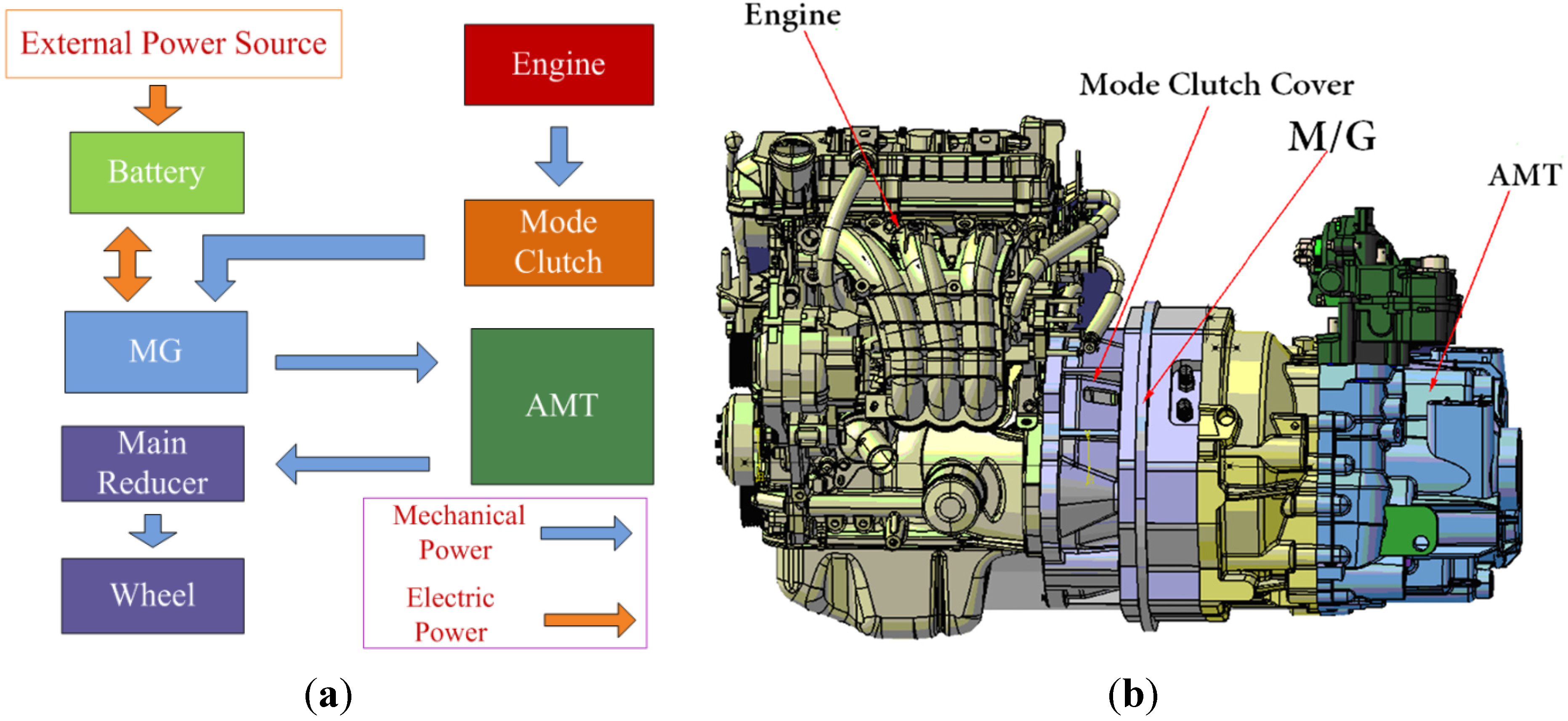
The structure diagram of the PHEV powertrain adopted in this paper is shown in Figure 1. The main components of the powertrain are the engine, the mode clutch which is connected in hybrid driving mode and disconnected in motor driving mode, the motor, the wheel, the main reducer and the transmission, which consists of five forward gears and one reverse gear. The main difference between the conventional shifting process and shifting without clutch is that the inertia of the components driving the synchronizer in the two processes is significantly different. In the shifting process without clutch, the inertia of the synchronizer input end includes more inertia of the motor rotor and the engine flywheel than the conventional synchronizer input end.
Figure 1. (a) The structure diagram of PHEV powertrain (MG: Motor/Generator); (b) The structure diagram of powertrain in the 3D software.
Energies 05 03094 g001
The basic idea of AMT shifting without clutch is that in the shifting process, the AMT control system can realize the communication with the engine controller and the motor controller by CAN bus, and the input torque and speed of AMT can be regulated to achieve fast synchronization of the driving and driven gears of AMT by controlling the engine and motor. Simultaneously, the speed, torque and position of the select motor and shift motor can be controlled accurately by the AMT control system to achieve the shifting action quickly and realize the automatic shift without clutch.
In the conventional shifting process, the main effect factors of shifting quality include the shift jerk, the shift time and the slipping friction work. However, in the shifting process without clutch, the main effect factors of shift quality are as follows [9]:
(1) The Shift Time
The shift time of the shifting process without clutch includes the time t1 of decreasing the output torque of the engine and motor, the time t2 of separating the synchronizer, the time t3 of gear selection, the time t4 of regulating the speed of the engine and motor, the time t5 of the synchronizing process of the synchronizer and shifting to the target gear, and the time t6 of restoring the powertrain torque after shifting. The equation of the total shift time is as follows:
tshf = t1 + t2 + max(t3,t4) + t5 + t6
(2) The Shift Jerk
The shift jerk is the rate of change of vehicle longitudinal acceleration, which is the important parameter for evaluating the shifting quality. The equation of shift jerk is as follows:
j = d a ( t ) d t = d 2 v ( t ) d t 2
where a(t) is the vehicle longitudinal acceleration, and v(t) is the vehicle longitudinal velocity.

3. Dynamic Analysis of AMT Shifting without a Clutch

3.1. Dynamic Model for AMT Shifting

The process of AMT shifting without a clutch can be divided into five phases [10]: (1) decreasing the engine and motor torque; (2) shift off; (3) adjusting engine and motor speed; (4) shift on; (5) restoring the engine and motor torque. To analyze the dynamic characteristics of each phase of the shifting process, a dynamic model for AMT shifting without a clutch is built up as shown in Figure 2.
Figure 2. Dynamic model for AMT shifting without a clutch.
Energies 05 03094 g002
where C is the mode clutch, which is connected in hybrid driving mode and disconnected in motor driving mode; S is the synchronizer, Je is the equivalent moment of inertia of the engine and the driving parts of the clutch, Jm is the moment of inertia of the motor, Jc is the equivalent moment of inertia of the driven parts of the clutch and the transmission input shaft, Jt_o is the equivalent moment of inertia of the transmission output shaft, Te is the engine torque, ωe is the engine speed, Tm is the torque transmitted by the motor, Tc is the torque transmitted by the clutch, ωc is the speed of the driven parts of the clutch, Tt_r is the external resistance torque of the transmission output shaft, ωt_o is the speed of the transmission output shaft, ig(n) is the transmission ratio of the n gear (n = 1st, 2nd, …, 5th), Tt_io is the torque transmitted from the input shaft to the output shaft, Tt_oi is the torque transmitted from the output shaft to the input shaft. The relationship between Tt_oi and Tt_io is as follows:
T t _ o i = T t _ i o i g ( n ) η T
where ηT is the transmission efficiency.

3.2. Dynamic Analysis of AMT Shifting without Clutch

Taking the upshift from 1st to 2nd gear as an example, the dynamic characteristics of the shifting process are analyzed [11,12,13]. In the normal driving and shifting process without clutch, there is ωe = ωc = ωt_oig(n). When the vehicle is driving on the 1st gear, the ig(n) is i1, and the dynamic equations can be expressed as follows:
{ ( J e + J m + J c + J t _ o i 1 2 ) ω e = T e + T m T t _ r i 1 a = d v d t = r i 0 i 1 d ω e d t = r i 0 [ ( J e + J m + J c ) i 1 + J t _ o / i 1 ] ( T e + T m T t _ r i 1 )
where i0 is the main reducer ratio, r is the wheel radius. The equation of shift jerk is as follows:
j = d a d t = r i 0 [ ( J e + J m + J c ) i 1 + J t _ o / i 1 ] ( d ( T e + T m ) d t d T t _ r i 1 d t )
Due to the short shift time, the external resistance is assumed to be constant when the shifting action is performed on flat road, i.e.:
d T t _ r d t = 0
So Equation (5) can be simplified as follows:
j = d a d t = r i 0 [ ( J e + J m + J c ) i 1 + J t _ o / i 1 ] d ( T e + T m ) d t
From the Equation (7) we can know that the shift jerk value is related to the change of the synthetic torque of the engine and motor. According to the reference value of the shift jerk, the equation of value range for the synthetic torque of the engine and motor can be obtained as follows:
d ( T e + T m ) d t j r e f i 0 r [ ( J e + J m + J c ) i 1 + J t _ o / i 1 ]
where jref is reference value of the shift jerk. The recommended values are 10 m/s3 and 17.64 m/s3 respectively in Germany and China.

3.2.1. Dynamic Analysis of Pre-Shifting

The dynamic characteristics of this phase are the same as that of normal driving. When the transmission input torque becomes zero, the transmission can shift off to the neutral gear. Otherwise, the engine speed will increase sharply due to the abrupt decrease of the load. Additionally, when the meshing gears are loaded, shifting off can lead to excessive wear of the gear faces. Shifting off can be easily achieved without excessive wear of the gear faces when zero torque is transmitted to the driving shaft of the synchronizer.

3.2.2. Dynamic Analysis after Shifting off

The power is interrupted after shifting off. In this phase, the transmission does not transmit the torque, i.e., Tt_io = 0. The equations of kinematics and dynamic relationship are as follows:
{ ω e = ω c ω c ω t _ o i 1 ( J e + J m + J c ) ω e = T e + T m J t _ o ω t _ o = T t _ r

3.2.3. Dynamic Analysis of Synchronization

Because the speed regulating performance of the motor is better than the engine, the motor is used to adjust the speed of the driving parts for the synchronizer.
(1) The active synchronization of the motor
In this phase, the dynamic equations of the input parts of the transmission are as follows:
{ ( J e + J m + J c ) ω e = T e + T m t s y n = ω 1 ω 2 J e + J m + J c T e + T m d ω
where ω1 is the input speed of the transmission before synchronization, ω2 is the input speed of the transmission after synchronization.
In the synchronizing process, the engine and motor torque do not change, so Equation (10) can be simplified as follows:
{ t s y n = J e + J m + J c T e + T m ( ω 2 ω 1 ) ω 1 = i 1 ω t _ o 1 ω 2 = i 2 ω t _ o 2
where ωt_o1 is the output speed of the transmission before synchronization, ωt_o2 is the output speed of the transmission after synchronization.
In the shifting process, the change of vehicle speed is very small, so we can consider ωt_o1 is approximately equal to ωt_o2, so the equations of the input speed relationship are as follows:
{ ω 2 = i 2 i 1 ω 1 ω 2 ω 1 = ω 1 ( i 2 i 1 1 )
The synchronizing process includes two phases: the active synchronization of the motor and the synchronization of the synchronizer. The equations of speed difference of the driving and driven parts for the synchronizer are as follows:
{ Δ ω t _ o = ω 1 ( 1 i 1 1 i 2 ) Δ ω = ω 2 ω 1 = i 2 Δ ω t _ o Δ ω t _ o = Δ ω t _ o 1 + Δ ω t _ o 2
where ∆ωt_o1 is the speed difference removed by the motor, ∆ωt_o2 is the speed difference removed by the synchronizer.
Thus, using Equations (11) and (13), the active synchronization time of the motor is:
t s y n 1 = ( J e + J m + J c ) i 2 Δ ω t _ o T e + T m
(2) The synchronization of the synchronizer
In this phase, the dynamic equations of the input parts of the transmission are as follows:
{ ( J e + J m + J c ) ω e = T t _ o i T t _ o i = T s y n i 2
The equation of the synchronizing torque is as follows:
T s y n = F a f R sin α
where Tsyn is the synchronizing torque in the synchronizer cone, Fa is the shifting force applied to the synchronizer, R is the average effective radius, f is the friction coefficient between the friction surfaces of the ring and the ring gear, and α is the cone angle of the ring.
Using the Equations (15) and (16), we can obtain that:
( J e + J m + J c ) ω e = F a f R i 2 sin α
The synchronization time of the synchronizer is:
t s y n 2 = ( J e + J m + J c ) Δ ω c i 2 2 sin α F a f R
The total synchronization time of the synchronizing process is:
t s y n = t s y n 1 + t s y n 2 = i 2 ( J e + J m + J c ) ( Δ ω t _ o 1 T e + T m + Δ ω t _ o 2 i 2 sin α F a f R )
In traditional vehicles, the only way of reducing the synchronization time is to increase the synchronizing torque in the synchronizer or the shifting force applied to the synchronizer. As shown in Equation (19), for HEVs, the motor can output a large synchronizing torque to remove the larger speed differences of the synchronization process.

3.2.4. Shift on

After the synchronization, the speed difference of the driving and driven parts of synchronizer is zero. The shift on action can be performed soon after the output torques of the engine and motor are zero. Shifting on can be easily achieved when zero torque is transmitted to the driving shaft of the synchronizer.

3.2.5. Restoring the Engine and Motor Torque

After shifting, the engine and motor torque should be restored to the commanded level at an appropriate rate to avoid affecting the shift quality.

4. Coordinated Torque Control of the Engine and Motor

To meet the needs of the shifting control, the engine and motor output torques are coordinately controlled to the target torques. As shown in Figure 3, the target output torque for the engine is determined by the engine map data in the current state. By calculating the throttle opening in the current state and the actual limited throttle opening after a change, the actual engine output torque can be estimated [13,14].
(1) The target throttle opening θe_tar
According to the vehicle demand torque, the vehicle controller calculates the corresponding target engine output torque in the current state. In the steady condition, through the accurate bench calibration, the engine output torque is determined by the engine speed and the target throttle opening, i.e.:
θe_tar = f(Te_tar, ne)
(2) The engine output torque on the limited throttle opening state
According to the engine output torque in the current state and the target throttle opening θe_tar, the variable quantity ∆θ of the throttle opening needs to be limited. According to the limited throttle opening θe_act, the actual output torque for the engine can be calculated:
{ θ e _ a c t = f ( θ e _ t a r , Δ θ ) T e _ a c t = f ( θ e _ a c t , n e )
(3) The actual output torque for the engine and motor
The vehicle controller can calculate the real-time compensation torque Tm_act for the motor according to the vehicle demand torque Treq and the actual output torque of the engine. Thus, the total output torque of the engine and motor can be guaranteed to follow the vehicle demand torque, i.e.:
{ T e _ a c t = f ( θ e _ a c t , n e ) T m _ a c t = T r e q T e _ a c t
Figure 3. Engine map data.
Energies 05 03094 g003

5. Dynamic Coordinated Control Strategy for AMT Shifting without a Clutch

5.1. Shifting Control Flow

Based on the dynamic analysis for AMT shifting and the coordinated control idea of the torque and speed of the engine and motor, the flow chart of the AMT shifting control without clutch for PHEV is proposed as shown in Figure 4 [13]. In this paper, the AMT shifting process without clutch for PHEVs includes the following phases: the coordinated control of the engine and motor torque before shifting off, the speed synchronization control, the coordinated control of the engine and motor torque before shifting on, the engine and motor torque restoration after shifting.

5.2. Control Strategy for AMT Shifting without Clutch

5.2.1. The Coordinated Control of the Engine and Motor Torque before Shifting off

The goal of this phase is to complete the shifting off action smoothly and quickly. The shifting off action can be performed only when the input torque of the AMT transmission controlled by adjusting the engine and motor output torque is zero. Due to the hysteretic torque response of the engine, the following actions will be performed:
(1)
The throttle opening is controlled to reach the threshold value αmin in which the engine operates well.
(2)
The operating mode of the electric machine switches from the motor to the generator when the throttle opening reaches the threshold value αmin.
(3)
As the throttle opening is kept constant, the engine output torque can be obtained from the curve of steady output torque and speed acquired from the engine controller.
(4)
Based on the above engine output torque, the total output torque of the engine and the motor is controlled to be zero by controlling the motor output torque.
(5)
The shifting off action can be performed soon after the total output torque of the engine and the motor becomes zero.
Figure 4. Flow chart of AMT shifting control without clutch.
Energies 05 03094 g004

5.2.2. The Speed Synchronization Control

After shifting off, the input speed of the transmission can be adjusted to the target speed by regulating the motor speed. The synchronization process is completed when the speed difference of the driving and driven parts for synchronizer is zero.

5.2.3. The Coordinated Control of the Engine and Motor Torque before Shifting on

To improve the shift quality and reduce the shift jerk, the shifting on action can be performed only when the input torque of the transmission is zero. So the following actions will be performed:
(1)
After the speed synchronization, the operating mode of the electric machine switches from the motor to the generator.
(2)
The throttle opening is kept on the threshold value αmin, the engine output torque can be obtained from the curve of steady output torque and speed acquired from the engine controller.
(3)
Based on the above engine output torque, the total output torque of the engine and the motor is controlled to be zero by controlling the motor output torque.
(4)
The shifting on action can be performed soon after the total output torque of the engine and the motor becomes zero.

5.2.4. The Engine and Motor Torque Restoration after Shifting

After shifting, the engine and motor torque should be restored to the commanded level at an appropriate rate to avoid affecting the quality of the shift.

6. Simulation Analysis

Based on the Matlab/Simulink software, a PHEV simulation model is built up to analyze the above discussed shifting control strategy [15]. The vehicle and powertrain parameters are shown in Table 1.
Table 1. The vehicle and powertrain parameters.
ParametersValue
Unloaded/full load gross mass m/kg1320/1845
Air resistance coefficient Cd0.36
Frontal area A/m22.53
Tire radius r/m0.299
Main reducer ratio i03.894
Transmission ratio (AMT-5 gears)[3.615 2.042 1.257 0.909 0.902; 4.298]
Engine displacement/L1.124
Maximum power (kW)/speed (r/min)58/6000
Maximum torque (Nm)/speed (r/min)101/4000
MotorPermanent magnet synchronous motor
Rated/peak power (kW)18/35
Rated/peak torque (Nm)86/167
BatteryLithium ion battery
Capacity (Ah)/Rated voltage (V)40/360
The diagram of the PHEV simulation model, which includes the driver model, the control system model, the engine model, the motor model, the transmission model, the battery model and the vehicle dynamic model, is shown in Figure 5.
Figure 5. The diagram of the PHEV simulation model.
Energies 05 03094 g005
The simulation results of speed and torque response in the upshift process under driving conditions are shown in Figure 6. The shift off action is activated at about 19.2 s when the engine and motor torque decrease to the target torque, and the input torque of the transmission becomes zero. The target torque is set to zero to produce the maximal deceleration after the shift off phase is over. As the transmission is in the upshift condition, the engine and motor speed need to decrease. When the speed difference between driving and driven parts of the synchronizer approaches zero, the shift on action is triggered. When the shift on action is completed, the motor torque is restored quickly due to the fast response of the motor, and the engine torque is restored to the driver command level simultaneously. The total duration is about 0.8 s from the time the shift command is triggered until the shift on process is completed, which more efficiently reduces the time of shifting and the power interruption and restoration.
Figure 6. Simulation result for shifting.
Energies 05 03094 g006
As shown in Figure 7, the upshift and downshift quality is analyzed in the highway driving cycle. In the upshift and downshift process, the fluctuation range of the vehicle acceleration is less than 1 m/s2 and the vehicle acceleration changes very smooth. Additionally, due to the inertia of vehicle and the short shifting time, the synchronizing speed difference of the driving and driven parts of the synchronizer approaches zero. Thus, the proposed shifting method more efficiently reduces the shift jerk and improves the shift quality and the ride comfort.
Figure 7. Simulation results of the upshift and downshift quality.
Energies 05 03094 g007

7. Real Car Test and Test Result Analysis

To verify the proposed control strategy for shifting without clutch in this paper, a hybrid electric MIDI passenger car equipped with AMT was adopted as the test vehicle, as shown in Figure 8.
Figure 8. The test vehicle.
Energies 05 03094 g008
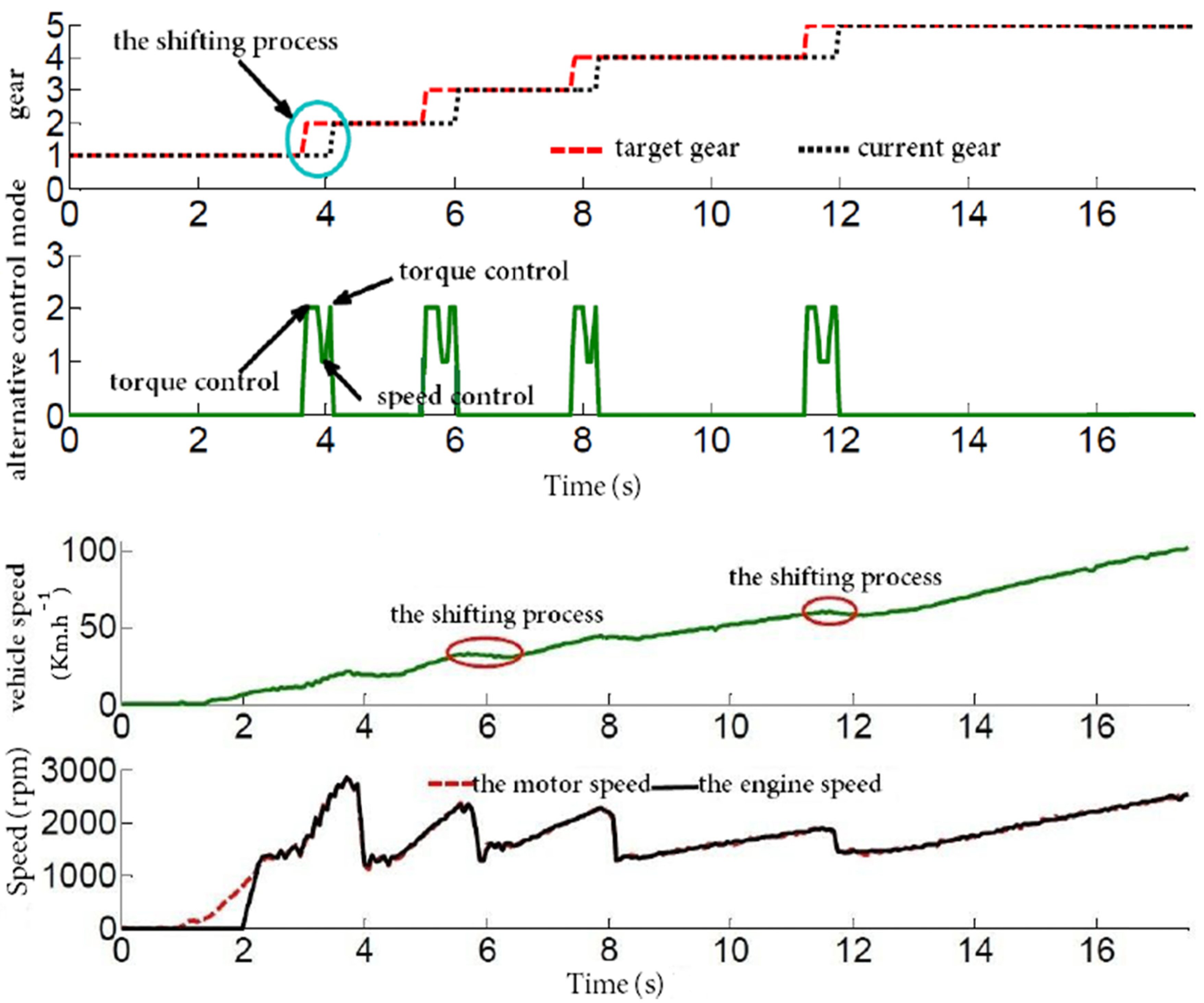
In the hybrid electric driving mode, typical test results of the speed and torque response for the engine and motor and the change of the vehicle velocity are shown in Figure 9. At the beginning of the shifting, the engine and motor output torques are controlled to smoothly achieve the shift off action. Then the engine and motor speed are adjusted to achieve the synchronization of the driving and driven parts of the synchronizer. When the shifting on action is achieved, the engine and motor output torques are restored to the driver command level. The total duration from the time the shift command is triggered until the shift on process is completed is approximately 0.8 s. Additionally, in the shifting process, the vehicle velocity hardly changes, the vehicle shifts smoothly and has a better ride comfort.
Figure 9. Test results of the shifting.
Energies 05 03094 g009

8. Conclusions

(1) The feasibility of shifting without clutch for a plug-in hybrid electric vehicle is studied in this paper. The dynamic characteristics of each phase of shifting process are analyzed in detail. A control algorithm is introduced that is capable of precise engine and motor output torque control.
(2) A control strategy in which torque and speed of the engine and motor are coordinatively controlled to achieve AMT shifting control without a clutch is presented with the aim of improving the shift quality. The coordinated control strategy is verified on a simulation platform and a test car. The results show that the new method of shifting without clutch produces improvements in the shifting time, which is about 0.8 s in the upshift process, torque interruption, and shifting comfort. These results prove that shifting without clutch is feasible and has the potential to overcome the disadvantages of the AMT.

Acknowledgments

This work was supported by the National High Technology Research and Development Program of China (2011AA112304, 2011AA11A228, 2011AA1290) in part, the International Cooperation Research Program of Chinese Ministry of Science and Technology (2011DFB70020) in part, and also the Program for New Century Excellent Talents in University (NCET-11-0785) in part.

References

  1. Samaras, C.; Meisterling, K. Life cycle assessment of greenhouse gas emissions from plug-in hybrid vehicles: Implications for policy. Environ. Sci. Technol. 2008, 42, 3170–3176. [Google Scholar] [CrossRef] [PubMed]
  2. He, H.W.; Xiong, R.; Chang, Y.H. Dynamic modeling and simulation on a hybrid power system for electric vehicle applications. Energies 2010, 3, 1821–1830. [Google Scholar] [CrossRef]
  3. Xiong, R.; He, H.W.; Sun, F.C.; Zhao, K. Online estimation of peak power capability of Li-Ion batteries in electric vehicles by a hardware-in-loop approach. Energies 2012, 5, 1455–1469. [Google Scholar] [CrossRef]
  4. Baraszu, R.C.; Cikanek, S.R. Torque Fill-In for an Automated Shift Manual Transmission in a Parallel Hybrid Electric Vehicle. In Proceedings of the American Control Conference, Anchorage, AK, USA, 8–10 May 2002; pp. 1431–1436.
  5. Jo, H.S.; Park, Y.I.; Lee, J.M.; Lee, H.-D.; Sul, S.-K. A development of an advanced shift control algorithm for a hybrid vehicles with automated manual transmission. Int. J. Heavy Veh. Syst. 2000, 7, 281–298. [Google Scholar] [CrossRef]
  6. Liao, C.L.; Zhang, J.Z.; Lu, Q.C. Coordinated powertrain control method for shifting process of automated mechanical transmission in the hybrid electric vehicle. Chin. J. Mech. Eng. 2005, 41, 37–41. [Google Scholar] [CrossRef]
  7. Pettersson, M.; Nielsen, L. Gear shifting by engine control. IEEE Trans. Control Syst. Technol. 2000, 8, 495–507. [Google Scholar] [CrossRef]
  8. Lu, X.T.; Hou, G.Z. Introduction of the AMT control system structure and main foreign AMT products. Chin. Automob. Technol. 2004, 5, 19–22. [Google Scholar]
  9. Ye, M.; Qin, D.T.; Liu, Z.J. Shift performance control for mild hybrid electric vehicle equipped with automatic manual transmission. Chin. J. Mech. Eng. 2009, 45, 108–114. [Google Scholar] [CrossRef]
  10. Zhong, Z.; Kong, G.; Yu, Z. Shifting control of an automated mechanical transmission without using the clutch. Int. J. Automot. Technol. 2012, 13, 487–496. [Google Scholar] [CrossRef]
  11. Glielmo, L.; Iannelli, L.; Vacca, V. Gearshift control for automated manual transmissions. IEEE/ASME Trans. Mechatron. 2006, 11, 17–26. [Google Scholar] [CrossRef]
  12. Galvagno, E.; Velardocchia, M.; Vigliani, A. Dynamic and kinematic model of a dual clutch transmission. Mech. Mach. Theory 2011, 46, 794–805. [Google Scholar] [CrossRef]
  13. Kulkarni, M.; Shim, T.; Zhang, Y. Shift dynamics and control of dual-clutch transmissions. Mech. Mach. Theory 2007, 42, 168–182. [Google Scholar] [CrossRef]
  14. Lin, C.C.; Peng, H.; Grizzle, J.W. Power management strategy for a parallel hybrid electric truck. IEEE Trans. Control Syst. Technol. 2003, 11, 839–849. [Google Scholar] [CrossRef]
  15. Zhang, Y.; Chen, X.; Zhang, X. Dynamic modeling and simulation of a dual-clutch automated lay-shaft transmission. J. Mech. Des. 2005, 127, 302–307. [Google Scholar] [CrossRef]