Article

Micromachining of Biolox Forte Ceramic Utilizing Combined Laser/Ultrasonic Processes

by
Basem M. A. Abdo
1,2,*,
Syed Hammad Mian
1,
Abdualziz El-Tamimi
2,
Hisham Alkhalefah
1 and
Khaja Moiduddin
1
1
Advanced Manufacturing Institute, King Saud University, Riyadh 11421, Saudi Arabia
2
Industrial Engineering Department, College of Engineering, King Saud University, P.O. Box 800, Riyadh 11421, Saudi Arabia
*
Author to whom correspondence should be addressed.
Materials 2020, 13(16), 3505; https://doi.org/10.3390/ma13163505
Submission received: 6 July 2020 / Revised: 2 August 2020 / Accepted: 6 August 2020 / Published: 8 August 2020
(This article belongs to the Special Issue Recent Advances in Ceramic Manufacturing)

Abstract

:
Micromachining has gained considerable interest across a wide range of applications. It ensures the production of microfeatures such as microchannels, micropockets, etc. Typically, the manufacturing of microchannels in bioceramics is a demanding task. The ubiquitous technologies, laser beam machining (LBM) and rotary ultrasonic machining (RUM), have tremendous potential. However, again, these machining methods do have inherent problems. LBM has issues concerning thermal damage, high surface roughness, and vulnerable dimensional accuracy. Likewise, RUM is associated with high machining costs and low material-removal rates. To overcome their limits, a synthesis of LBM and RUM processes known as laser rotary ultrasonic machining (LRUM) has been conceived. The bioceramic known as biolox forte was utilized in this investigation. The approach encompasses the exploratory study of the effects of fundamental input process parameters of LBM and RUM on the surface quality, machining time, and dimensional accuracy of the manufactured microchannels. The performance of LRUM was analyzed and the mechanism of LRUM tool wear was also investigated. The results revealed that the surface roughness, depth error, and width error is decreased by 88%, 70%, and 80% respectively in the LRUM process. Moreover, the machining time of LRUM is reduced by 85%.

1. Introduction

Micromachining has acquired tremendous interest, as microcomponents can be seen in a broad array of applications, notably in the automotive, aerospace, electronics, green energy, and biomedical sectors [1]. Such microproducts or systems are typically made from difficult-to-machine materials, such as ceramics, metals, polymers, composites, etc., and represent intricate shapes [2]. The microcomponents consist of microfeatures such as microchannels, microholes, micropockets, etc., the accuracy of which is crucial to their effectiveness [3]. For example, the dimensional accuracy of microchannels plays a pivotal role in biomedical applications such as microfluidic systems [4]. The manufacturing of the microchannels in bioceramic materials has always been a tedious task and it is often challenging to refine and form them efficiently and effectively using traditional processing methods. Bioceramic materials are considered hard to machine by conventional methods of turning, milling, drilling, etc. due to their inherent characteristics including high hardness and brittleness along with low fracture toughness resulting in excessive wear of the tool, high material cracking, low efficiency and high machining costs. Besides, properties like chemical inertness and low electrical conductivity make bioceramics machining a challenge through the use of electrical and chemical processes. As a consequence, there is a restriction in commercial applications for bioceramic materials due to the high machining costs.
Laser beam machining (LBM) has been one of the nontraditional technologies of machining that can be extended to almost all materials heedless of their mechanical, electrical, and thermal properties [5]. Compared to conventional machining approaches, it has many benefits, including high versatility in machining complex shapes, contactless material removal, no tool wear, simple and inexpensive micromachining, etc. In LBM, the material is extracted using a high-power laser pulsed at a particular spot on the object to be machined. Numerous studies have highlighted the feasibility of using LBM to produce microfeatures on an array of materials including metals [6,7], alloys [8,9,10], polymers [11,12,13,14], glass [15,16,17], and ceramics [18,19,20,21,22]. For example, Leitz et al. [23] illustrated the laser ablation process of the metals and concluded that the pulse duration of the laser source seriously impacts its output. They reported that the nanosecond laser system resulted in maximum ablation efficiency, while the ablation performance of the pico- and femtosecond system were considerably lower. As stated by Gaudiuso et al. [24], the pulse repetition, scan rate, pulse interval, and pulse intensity are the critical variables that would strongly affect the laser cutting quality and functionality. Thus, a viable solution to the processing parameters is essential to get efficient and effective machining through laser systems. To facilitate the femtosecond laser processing of the sintered alumina surface, Oosterbeek et al. [25] undertook the optimization of laser processing parameters. The focal length and depth, laser power, percentage of passes, and material translation velocity were optimized for the removal rate and better performance in this analysis. This operation greatly increased machining speeds of alumina surface, thereby minimizing the costs, and making femtosecond laser machining a feasible choice for industrial consumers. Olbrich et al. [26] also explored the ablation of thin metal films using variable-pulsed laser radiations. They studied the ablation characteristics of several metals, namely aluminum, gold, molybdenum, nickel, and platinum focusing on pulse duration for single-pulsed ultrafast laser radiation. Similarly to LBM, rotary ultrasonic machining (RUM) has also shown its capabilities for producing microfeatures in hard-to-cut materials such as advanced ceramics, glasses, and alloys. RUM can be described as a hybrid process combining the material removal of both diamond grinding and stationary ultrasonic machining (USM) [27]. It is a purely mechanical and precise method of machining, primarily used for finishing and microproduction. RUM is frequently involved in the production of hard and brittle materials like ceramics [28,29], silicon [30], composites [31], glass [32,33] and crystals [34]. In RUM, a higher material removal rate (MRR) can be reached as opposed to diamond grinding or USM [35]. RUM also has characteristics of superior surface finish, lower cutting forces, and tool wear, as well as hardly any constraint due to the electrical or chemical properties of substrate materials [36]. Besides, the mechanical and metallurgical properties of RUM are not disturbed, and there is no thermal damage to the work material [37].
Researchers are attracted to establish hybrid micromachining processes (HMMP) in response to challenges in the micromachining realm and to resolve the shortcomings of individual LBM and RUM processes. In HMMP, two or more processes for machining are coupled to maximize the benefits of constituent processes while reducing their detrimental implications when implemented independently [38]. For example, in the published paper [39], a hybrid of laser-assisted micromilling was applied to produce microscale grooving on H-13 hard steel. Findings demonstrated that the precision of the groove depth was boosted with the assistance of laser heating—the cutting force and the surface roughness decreased by 17% and 36% respectively. Similarly, the hybrid of laser and diamond grinding was introduced by Fortunato et al. [40] to grind silicon nitride. Analysis indicated a drop of 30 percent in cutting force while using the hybrid method compared to the cutting force of single-diamond grinding. In another study [41], a laser water-jet hybrid process was employed to machine silicon carbide materials. Al-Ahmari et al. [42] utilized the electric-discharge machining (EDM) process to finalize the microholes that were premachined by laser processing in nickel–titanium material. Laser-guided grinding of zirconia ceramic material was also included in [43]. The outcomes reported a reduction of the grinding force and reduction of the tool damage in the assisted processes. Likewise, Trotta et al. [44] realized the innovative modification of microinjection molding through the proposal of detachable and personalized inserts. Such inserts were engineered using high-resolution femtosecond laser and µEDM machining processes. Laser micromachining was capable of processing, with increased removal rates, large surface areas with comparatively small depth attribute, while µEDM, was employed to attain high aspect ratio structures owing to the low removal efficiency.
The literature survey conspicuously demonstrates that the utilization of bioceramics in industries is hampered by the intricacy, high costs, and prolonged time involved with their machining. Thus, more cost-effective methods of machining bioceramics should be implemented. LBM and RUM are effective and reliable means for precision micromachining of bioceramic materials. Nonetheless, they both have their respective fundamental issues. LBM has problems with thermal damage, high surface roughness, and vulnerable dimensional precision [45,46,47]. RUM is also associated with high machining costs and low MRR [48]. To surpass their limits, a combination of LBM and RUM processes, known as laser ultrasonic rotary machining (LRUM), has been employed in the current study, as shown in Figure 1. The novelty of this work is that it addresses the challenge of machining microchannels (≤800 × 800 μm) in hard-to-machine bioceramics. Until now, according to the authors, very few studies have been published on the micromachining of biolox forte bioceramics. This work introduces an additional understanding of using LRUM to process these challenging-to-machine materials for even further reduction in machining costs and surface roughness. Furthermore, the impetus underlying the combination of the LBM and RUM processes stems from the fact that these two methods have many parallels including (i) both processes can be utilized to machine materials that are hard to cut like glass, ceramics, etc., (ii) both LBM and RUM can be employed to generate microfeatures, and (iii) can be adapted to machine complex shapes.
The following steps are adopted while executing the methodology of LRUM in this investigation: the LBM under its optimized parameters is first used as a prevailing machining method to produce microchannels in alumina bioceramic. It has been utilized to produce the substrate’s bulk geometry owing to its high MRR and lower machining costs. In the subsequent step, the RUM under its streamlined process conditions, is used as a finishing tool to finalize the geometry of premachined microchannels. The reasons for employing RUM to formalize the geometry are high dimensional precision and low tool wear. Furthermore, in this analysis, the different sizes of the microchannels are examined. Multi-objective genetic algorithm (MOGA) is used to optimize fundamental input parameters for both LBM and RUM processes. The performance indicators, namely dimensional accuracy of the channels including depth error (DE) and width error (WE) as well as surface quality including surface roughness and surface morphology are explored. Additionally, the correlation between the tool wear of RUM and LRUM methods is also analyzed.

2. Material and Method

Biolox forte ceramic from CeramTec, Plokhin root, Germany was chosen as the workpiece material. It consists of ultra-pure aluminum oxide ceramic (Al2O3, 99.97) and meets the highest standards of biocompatibility, longevity, and dimensional stability [49]. The dimensions of all the biolox forte samples used in the experiments were 50 mm in length, about 10 mm wide, and 10 mm thick. Table 1 details the mechanical and thermal properties of biolox forte as per the supplier [50].
In this study, Lasertec 40 from Deckel-Maho-Gildemeister (DMG) Mori, Billefield, Germany was considered as a primary process for the manufacture of the microchannels in biolox forte ceramic. Lasertec 40 (see Figure 2a) is commonly used with its preset conditions, including 30 μm laser beam spot size, 30 W maximum power, 1064 nm continuous wavelength, and Nd: YAG pulsed mode. The laser with a spot size of 30 μm follows the Gaussian mode and emits a laser intensity of 42,441 kW/mm2 as a result of a pulse train with a pulse length of 10 μm and pulse duration of 10 μs. The illustrative working principle of Lasertec 40 is depicted in Figure 2b.
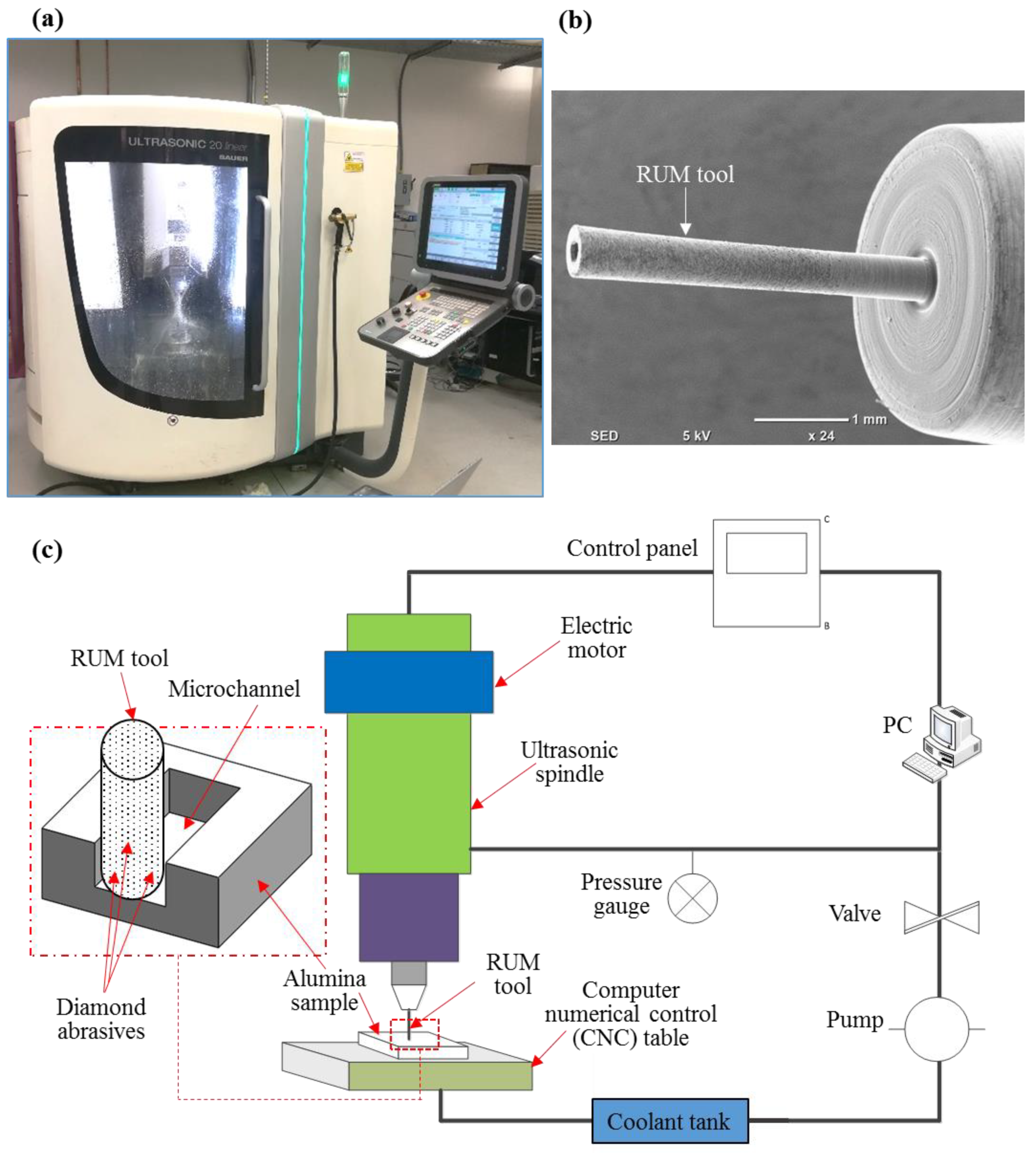
Ultrasonic 20 linear which is used to finish the premachined microchannels also comes from DMG Mori, Billefield Germany (see Figure 3a). It is a precision machine with five axes that is predominantly used for precise micromachining and finishing operations. In the current investigation, microRUM tools with an outer diameter of 0.8 mm and 0.5 mm given by Schott Company, Mainz, Germany are used. Figure 3b displays the microRUM tool sample and Figure 3c portrays RUM schematics along with the 3D schematics of the produced microchannels.
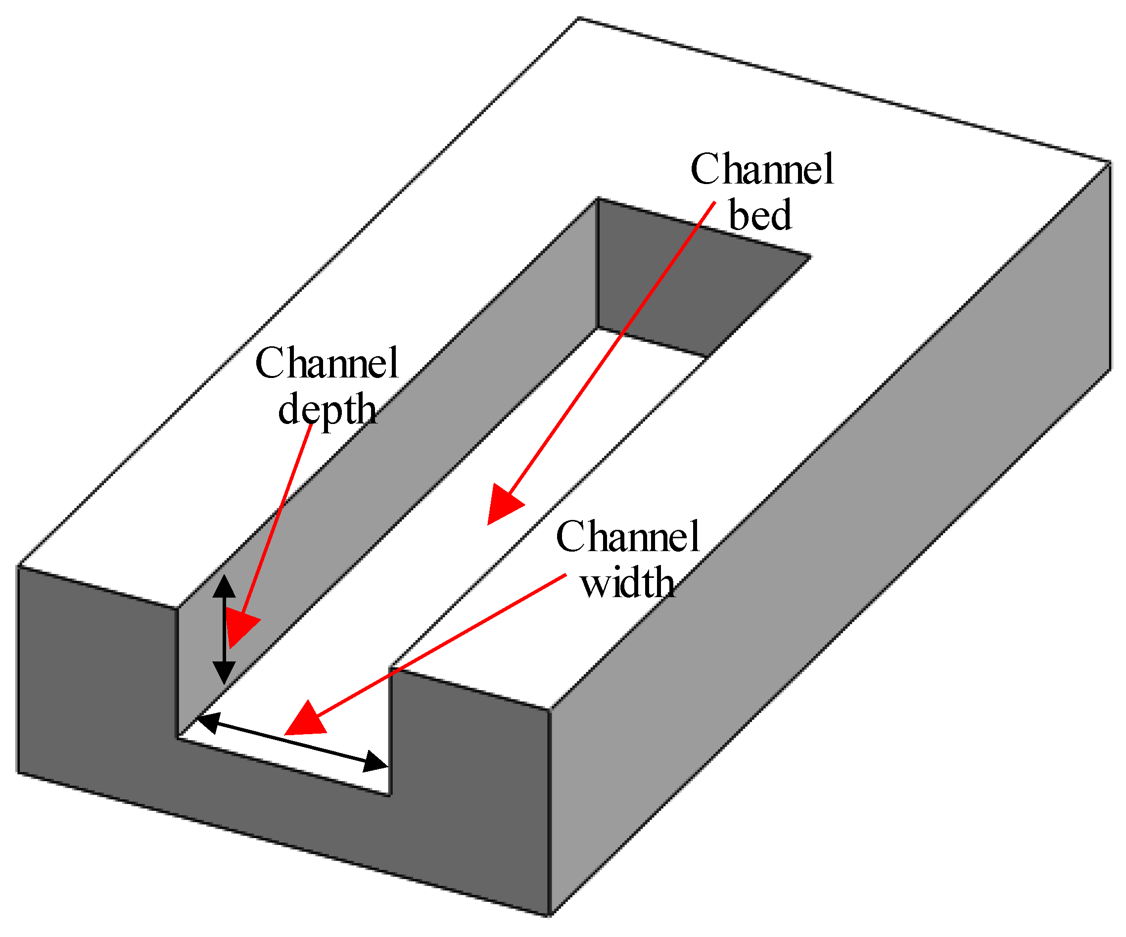
Microchannels were produced in five varying sizes and two kinds of the cross-sectional area comprising square and rectangular cross-sections. Table 2 enumerates the dimensions of the desired channel sizes. The channel sizes were chosen depending on the requirements of microfluidics as stated in [51,52,53]. The microchannel schematic can be seen in Figure 4.

2.1. Machining Conditions

Before the final experiments were implemented, the selection of the laser and RUM key input parameters was essential. In this analysis, the process parameter ranges were specified based on previous studies of laser machining [45,47,54,55,56,57] and RUM [58,59,60,61,62]. The preliminary experiments were also conducted to establish the exact levels of the process parameters which were later used for the final experiments. Table 3 demonstrates the parameters of LBM, RUM input factors, and their levels used in the experiments. The entire workflow is described in Figure 5.
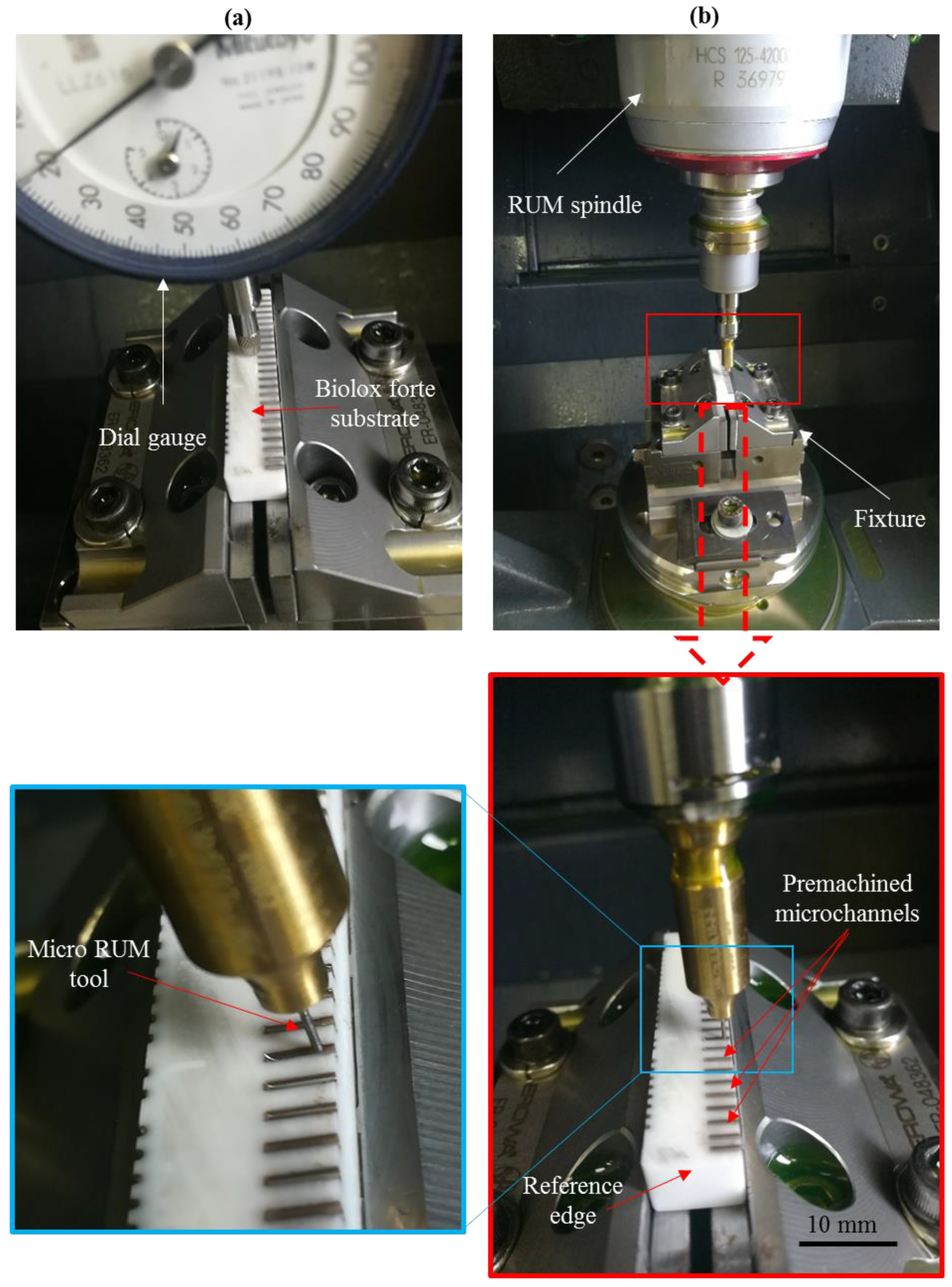
It should be emphasized that the method of machining using RUM in the premachined microfeatures was challenging due to the accompanying reasons. For example, the placing of the microRUM tool in the center of the premachined microchannel, the machine’s positioning accuracy, and the precision of the fixtures used. To resolve the above difficulties, the dial guage was used to establish the leveling of the workpiece, as shown in Figure 6a. In addition, one edge in Figure 6a of the workpiece that is the reference edge was chosen as the reference to direct the tool to the center of premachined microchannels as illustrated in Figure 6b. The workpiece measurements were determined automatically using a contact probe tool with a positioning error of ±2.5 μm. Additionally, the RUM microtools length and diameter were calculated and recalibrated using the integrated DMG laser tool length calibration method.

2.2. Multi-Objective Genetic Algorithm

It should be noted that twenty-five microchannels of each size were machined by using LBM and RUM following the design of experiment tables. The MOGA was used to minimize the surface roughness (Ra and Rt) and the dimensional errors (DE and WE) of the milled microchannels. The results of the optimization for each process were subsequently applied in the LRUM methodology. The chosen parameters of MOGA are depicted in Table 4.

2.3. Measurement Method

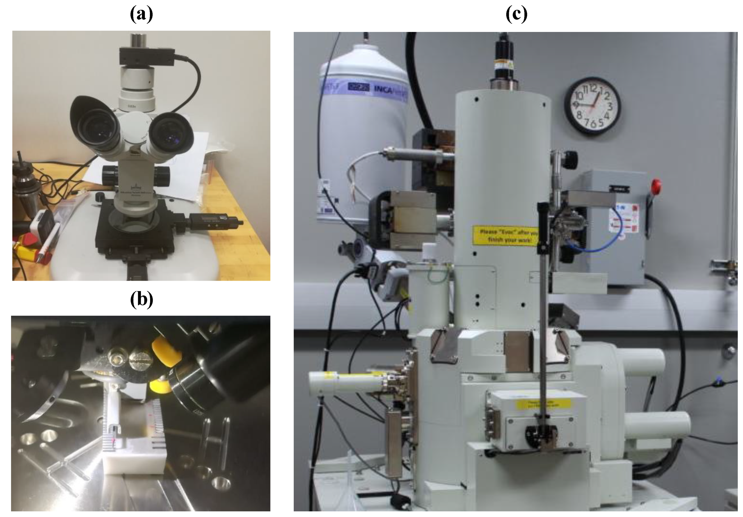
The geometries of the channels, including channel width and depth of channels (see Figure 4), were estimated using an optical microscope (see Figure 7a). Subsequently, by using Equations (1) and (2) respectively, the percentage of DE and WE was used for further analyses.
WE % = | M W D W D W | × 100
DE % = | M D D D D D | × 100
where MW is the estimated channel width following machining and DW is the required width, MD is the computed depth after machining, and DD is the desired depth. For example, 500 μm and 300 μm respectively, are the ideal width and depth for the channel size of 500 µm × 300 µm.
A 3D profilometer (DektakXT Stylus Profiler) from Bruker, MS, USA, was utilized to evaluate surface roughness by estimating arithmetical mean roughness (Ra) and a maximum height of the roughness profile (Rt) across every channel bed at six different spots. In this study, the Ra is utilized to quantify the surface roughness value because it has been the most common measure in the majority of the work that associates surface fatigue or failure to surface roughness. In medical applications also, that require microchannels, Ra is considered as the most important indicator of surface roughness [7,15]. The authors also measured some other roughness amplitudes such as Rq, Rv, and Rp. Hwoever, the obtained results followed the same trend as of Ra (Rq ≈ 1.3 Ra). Furthermore, the Ra is preferred over the root mean square (RMS) because Ra offers a holistic interpretation of the height variations of the surface and is less sensitive to high hills and troughs. In contrast, RMS is prone to the large peaks and valleys, where even a single high peak or imperfection within the microscopic surface morphology can elevate the RMS value more than the Ra value. For analysis, the mean of the five measurements is considered. Figure 7b presents the arrangement for determining the surface roughness. The microchannels were platinum-coated by including a thickness of 10 μm using JEOL Ltd.’s (Tokyo, Japan) JFC 1600 auto-fine coater to increase their clarity during electron microscopy scanning (SEM) study. A JEOL JEM-7500F scanning electron microscope (SEM), (JEOL, Tokyo, Japan) was used to investigate the surface morphology of microchannels as shown in Figure 7c. The machining time (MT) for all processes under analysis was determined by employing integrated MT measurement in both LBM and RUM.

3. Results and Analysis

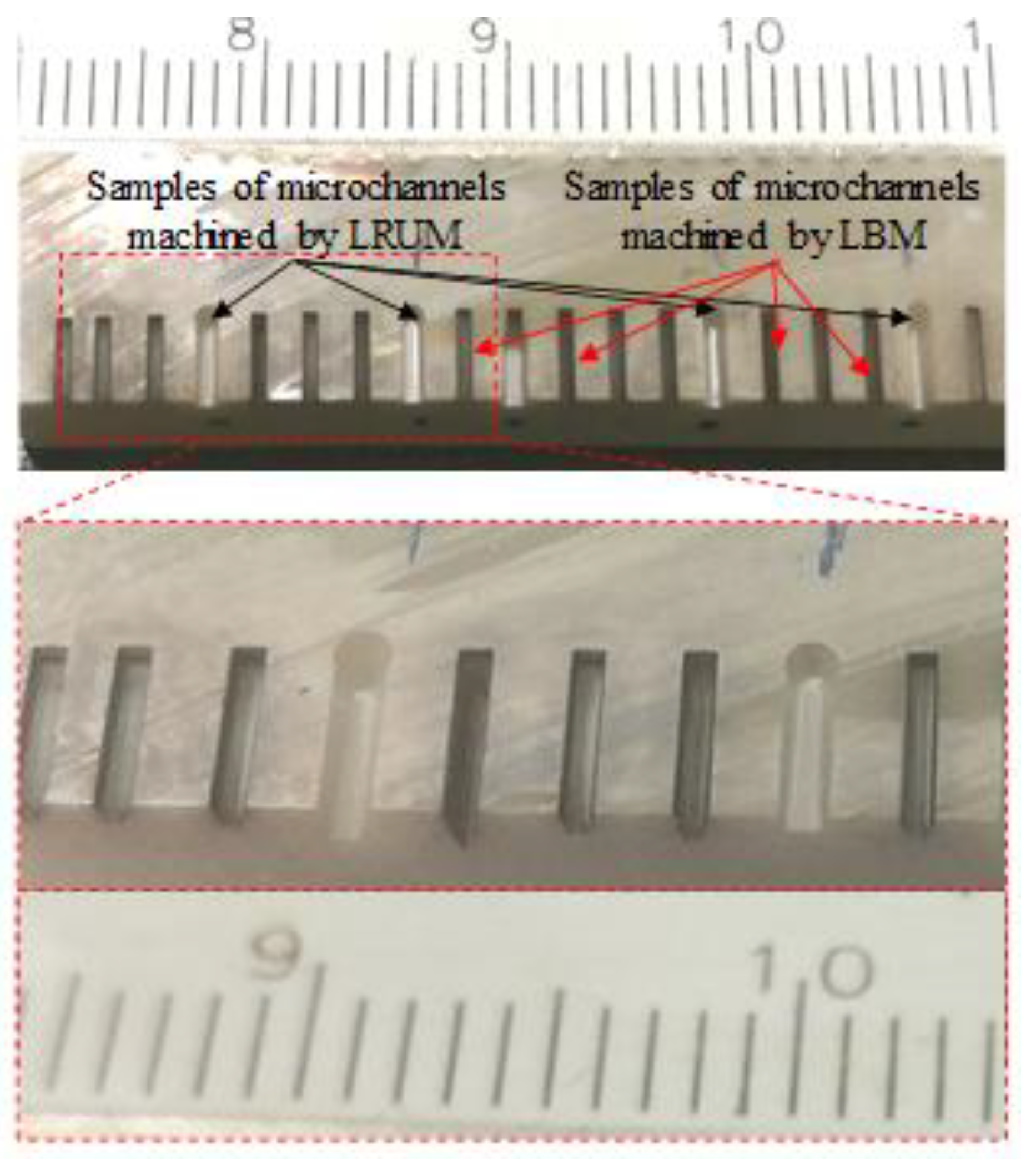
The five distinct sizes of microchannels were produced in biolox forte ceramic materials under optimal laser ablation conditions. The fabricated channels were subsequently postprocessed through RUM in the combined process. Microchannel samples produced under optimum LBM and LRUM conditions can be realized in Figure 8. The following paragraphs address the combined process results compared to the independent LBM and RUM processes.

3.1. Surface Roughness

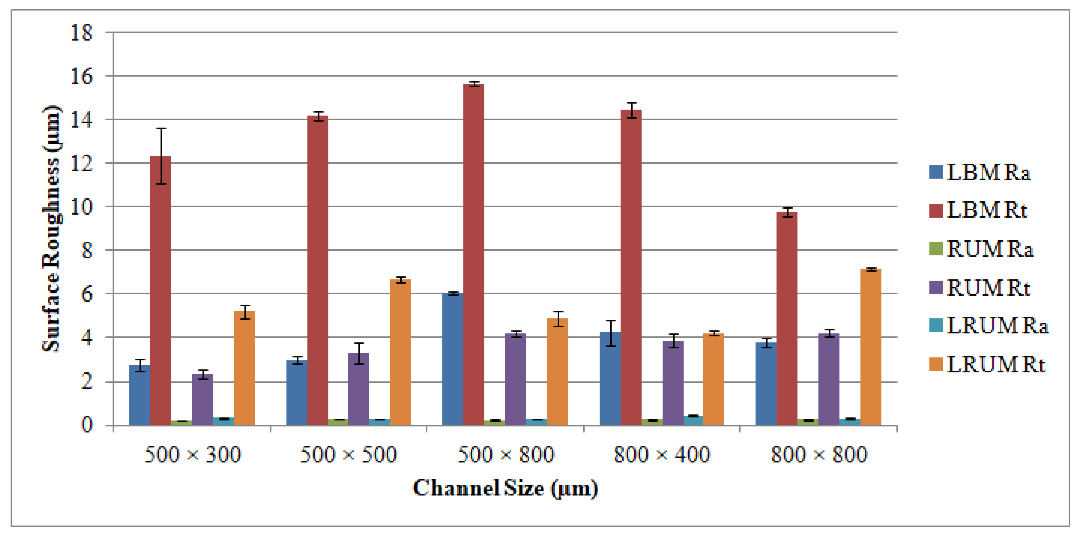
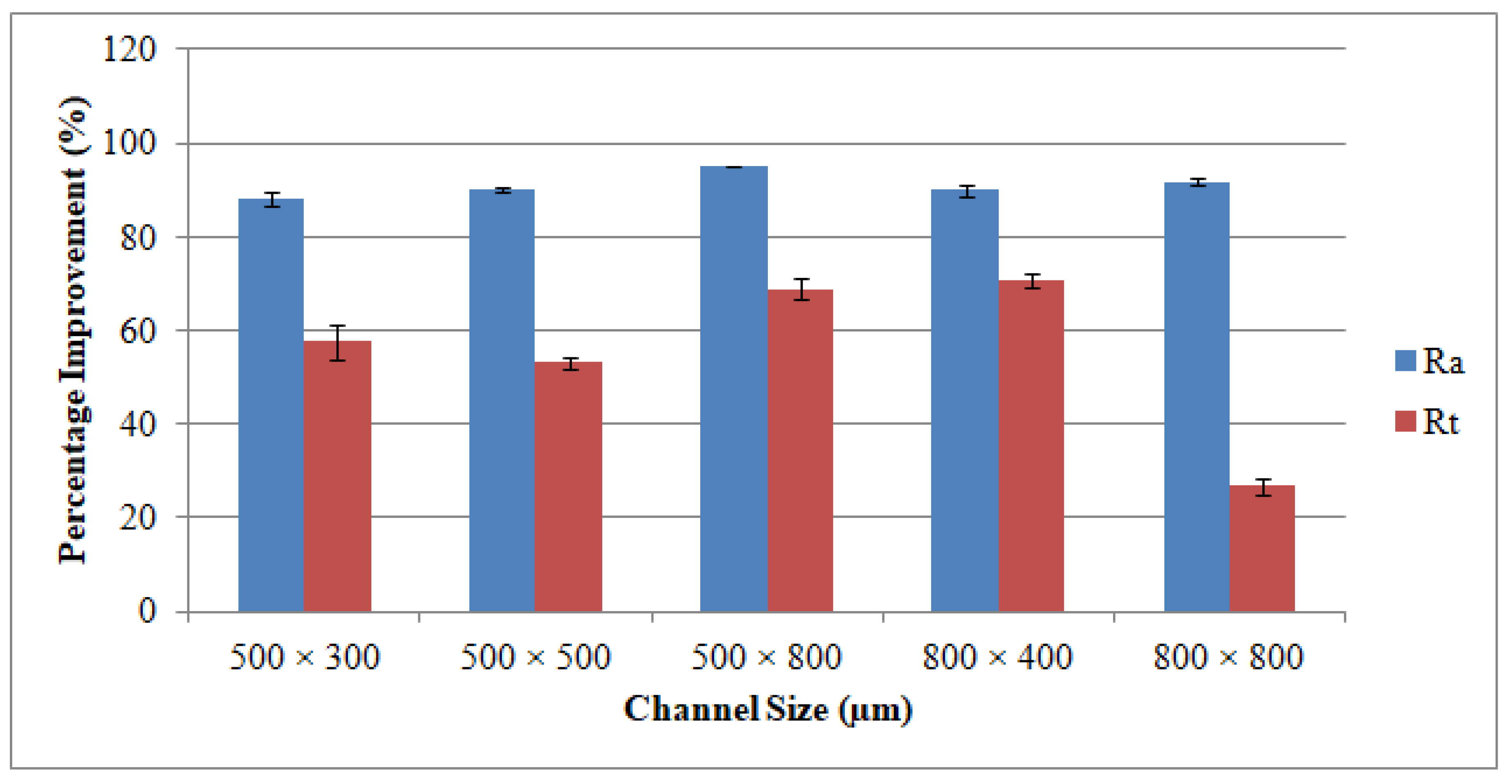
The plots shown in Figure 9 outline the surface roughness (Ra and Rt) of the different channels. The reported surface roughness estimates reflect the average measurements recorded at six random locations throughout the LBM scan directions and across the feed direction of the RUM tool. It could well be said that the Ra values extend from 2.76 to 6.06 μm and the Rt values vary from 9.82 μm to 15.67 μm for all channels produced in a biolox forte material using the LBM process. These values of roughness (Ra and Rt) can be attained at a pulse frequency of 5–7 kHz, laser intensity of 93–96 percent, and 100–200 mm/s of laser scanning speeds. The explanation for this finding is that the improvement in the pulse frequency results in a reduction of the laser energy while other parameters are unchanged. The lower laser power allows more unmolten materials to collect on the bed and sides of the ablated channel making the surface of the channel rougher. The roughness of the surface has been discovered to drop as laser intensity increases. It implies that low levels of intensity for ceramic material correlate to a nonuniform withdrawal of material which results in poor surface quality. It has also been noticed that the average temperature of the ablated channels decreases at greater levels of laser scanning speed (300 mm/s–400 mm/s). As a result, the molten content reduces and therefore the channel surface becomes rougher. Concerning the relationship between the channel size and the Ra (and Rt) values, the surface roughness becomes rougher when the channel depth increases in unchanged width. For instance, Ra values rise from 2.76 μm to 6.06 as the channel depth increases from 300 μm to 800 μm at a fixed width of 500 μm. This is because once the machined channel depth deepens, the laser loses its energy and it is harder to efficiently extract the fused mass, thereby creating the rougher surface. However on the other side, when the width increases to 800 μm the surface of the channel is smoother (Ra = 3.78 μm). Concerning the surface roughness of the RUM channels, the Ra and Rt values are found to be lower than those of the LBM outcomes. All the obtained values of Ra were less than 0.3 µm for all the fabricated channels by using RUM. There is no interesting correlation or connection between channel size and surface roughness for the channels formed by RUM and combined processes. A higher spindle speed of 7000 rpm, a lower feed rate of 0.4 mm/min, a cutting depth of 0.025 mm, a medium to high vibration amplitude of 20–25 µm and a 20–25 kHz frequency were used to achieve the Ra and Rt values. In general, it can be inferred from Figure 9 that the LRUM findings are close to the RUM responses. While comparing LBM with LRUM performance, the surface roughness has improved significantly by more than 88 percent for Ra and 26 to 72 percent for Rt in all channel sizes in the case of the LRUM combined process. For example, as shown in Figure 10, for the 800 µm × 400 μm size channel the Ra is decreased by 90 percent and the Rt by 72 percent. The uncertainties responsible for variation in the surface quality of different channels (acquired using LRUM) has been quantified using standard deviations (SD). The SD is represented using error bars in Figure 9 and Figure 10. There can be many uncertainties, such as tool wear, measurement errors, vibrations, operator experience, etc., that caused variance in the surface quality.
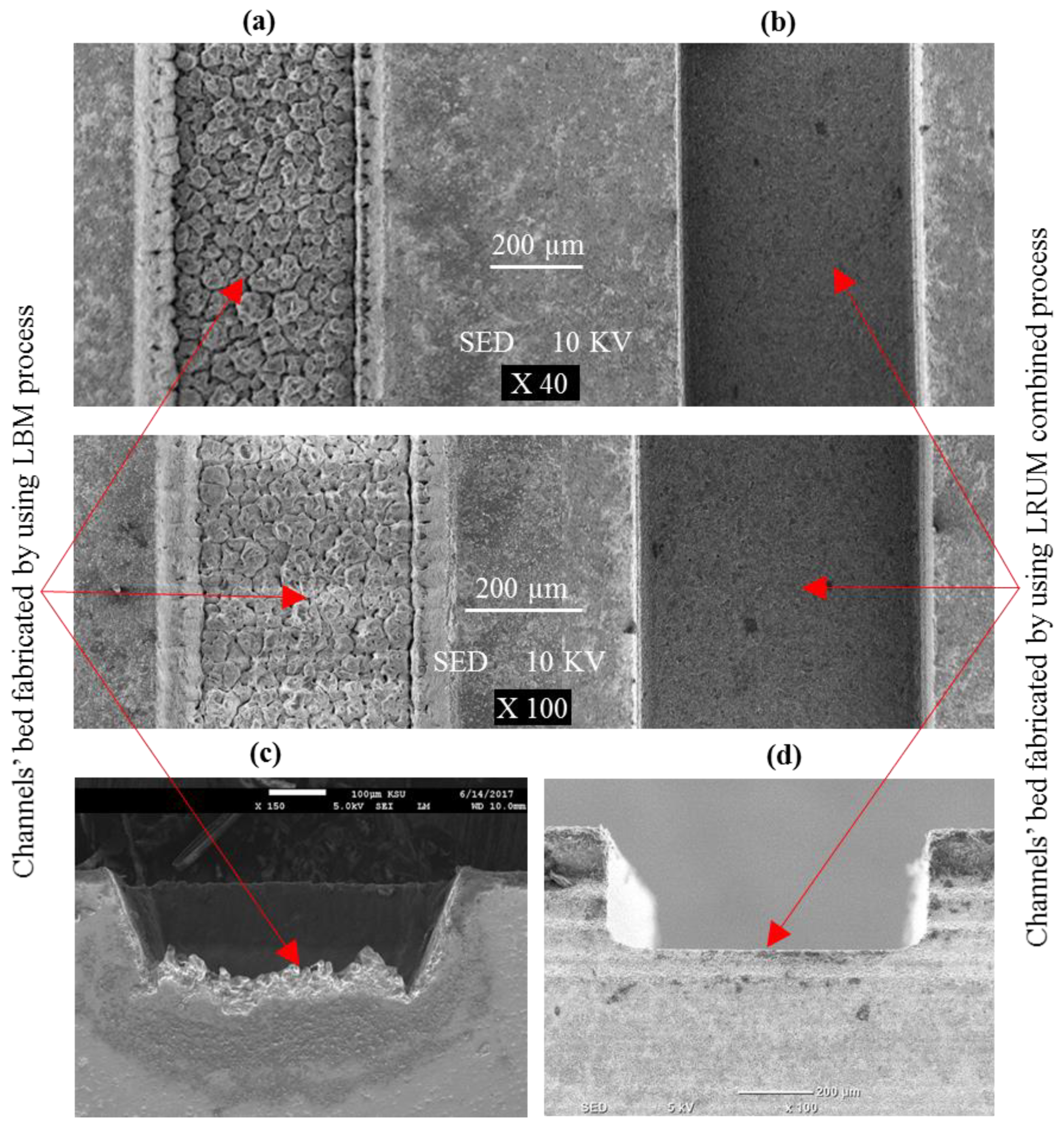
The analogy of the surface characteristics of a channel generated by LBM and LRUM processes is illustrated in Figure 11. Figure 11a,b shows the bed of the channel while Figure 11c,d represents the sides of the channel. The surface produced through the LRUM process is observed to be very smooth across the channel’s sharp edge. However, a rough surface morphology can be observed in the case of the channel generated by LBM. It is quite common for LBM parts to have a higher surface roughness. For example, in [63] the roughness (Ra) of the microchannels machined by using the Nd:YAG laser process reached up to 15 µm for the smaller channel size and 4 µm for the bigger channel size (1000 µm width). In another study, it was found that the surface roughness (Ra) varied between 1.5 µm and 4.8 µm for the microchannels machined in zirconia ceramic by the laser ablation process [55]. The surface roughness in terms of Ra was also found to be between 4.5 µm and 12 µm for the microchannels machined in alumina [64]. Generally, the higher surface roughness with LBM can be attributed to its high laser heat impact in proportion to the thickness of the test specimen. Additionally, the higher thermal damage and formation of the recast layer are the other reasons for poor surface roughness in LBM [65]. The rapid cutting speed (to achieve higher MRR) for LBM has indeed been the primary reason for its use in this research. This high speed, however, comes at the price of adverse and unfavorable surface integrity outcomes. The similar behavior of LBM was also reported by Holmberg et al. [66], who evaluated the performances of EDM, LBM, and abrasive water-jet machining. They found the highest surface roughness was for LBM amongst the three approaches. According to them, LBM could be an option for thin workpieces of less than 8 mm, but rigorous surface integrity investigations are then needed to assess the effect and the necessary postprocessing. It must also be acknowledged that the generated depth of the channels is more than the target depths in some channel sizes. The LRUM is unable to machine extra depth to maintain the dimensional accuracy of the channels as per the planned one, resulting in higher Ra and Rt values than the RUM results.

3.2. Dimensional Accuracy

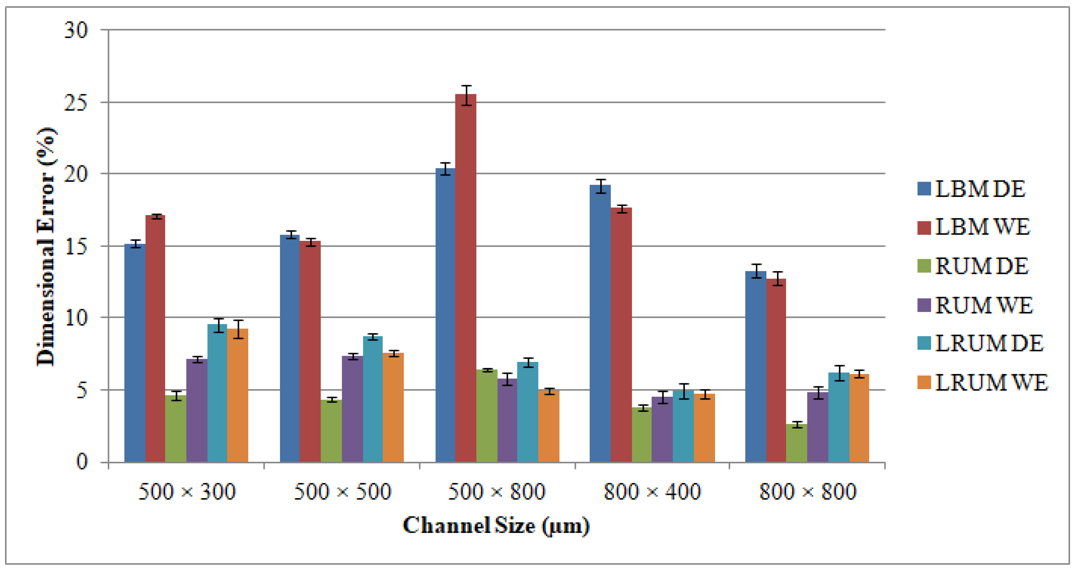
The graphs appear in Figure 12 encompass details on dimensional accuracy for different channels in terms of DE and WE. It must be emphasized that the channel width presumed in this study is the bottom width (see Figure 4), because the top widths produced have been found to meet the intended widths for all channel sizes. It simply indicates that there is no issue with the shielding effect of the molten material on the top surface and that the laser provides completely focused energy. In addition, the problem of tool wear is not detected at the beginning of machining the first cutting depth in RUM. In LBM, the DE is discovered to be positive (overcut), i.e., if the channel depths are lower than the channel widths, the depths created are larger than the depths intended. It appeared at channel sizes of 500 μm × 300 μm, 500 μm × 500 μm, and 800 μm × 400 μm. In contrast, the DEs are spotted to be negative (undercut), i.e., the depths produced are smaller than the expected depths if the depths of the channel are higher than the channel widths such as the channel size of 500 μm × 800 μm. This is because the laser loses its energy when the machined depth becomes deeper. Specifically, with an increase in channel depth, the DE increased from 15.2% for a channel size of 500 μm width × 300 μm depth to reach approximately 20.5% for a channel size of 500 μm width and 800 μm depth.
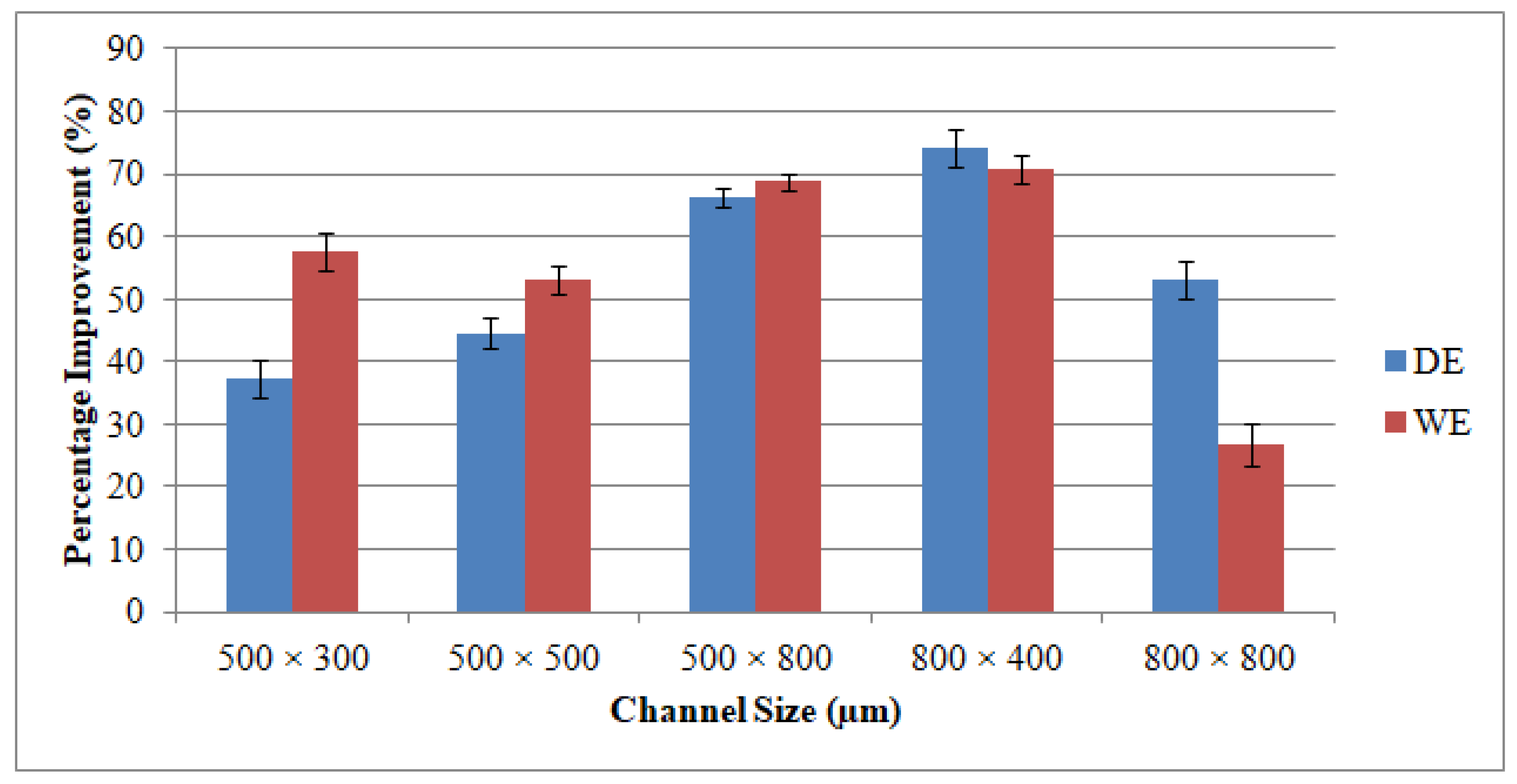
Taking into consideration LBM’s WE, it is noticed that the width values acquired for all channel sizes are below the anticipated widths. This is due to the inherent properties of the laser that it invokes some tapering as when the machining depth proceeds. The WE is larger than the DE in most manufactured channels. The higher WE can be noticed in the deeper channel size (500 μm × 800 μm). However, the minimum WE equivalent to 12.8 percent could be figured at the channel size of 800 μm × 400 μm. The DE and WE of RUM are always positive. This is because the outer diameter of the RUM tool (0.5 mm and 0.8 mm) is the tool’s nominal diameter. The effective diameter of the tool is greater than the nominal diameter due to the variation in the abrasive sizes of the diamond bonded to the tool. Abdo et al. [62] also observed and explained this phenomenon of overcutting during RUM because of the discrepancy in the grit size of the diamonds. With respect to the channels produced using the LRUM process, it is discovered that the DE and the WE are less than 10 percent for all the machined microchannel sizes. The increase in the percentage DE and WE of LRUM as opposed to the performance of LBM for all channel sizes can be realized in Figure 13. For example, using the LRUM procedure it is found that the DE and WE values in the 800 μm × 400 μm size channel are reduced by 74 percent and 72 percent respectively. The uncertainties that caused variation in DE and WE of different channels are also quantified using SD. The SD of dimensional errors is depicted in Figure 12 and Figure 13 utilizing error bars. There can be many uncertainties, including tool wear, measurement errors, vibrations, fixtures, ambient temperature, etc., that have produced variance in the dimensional errors.
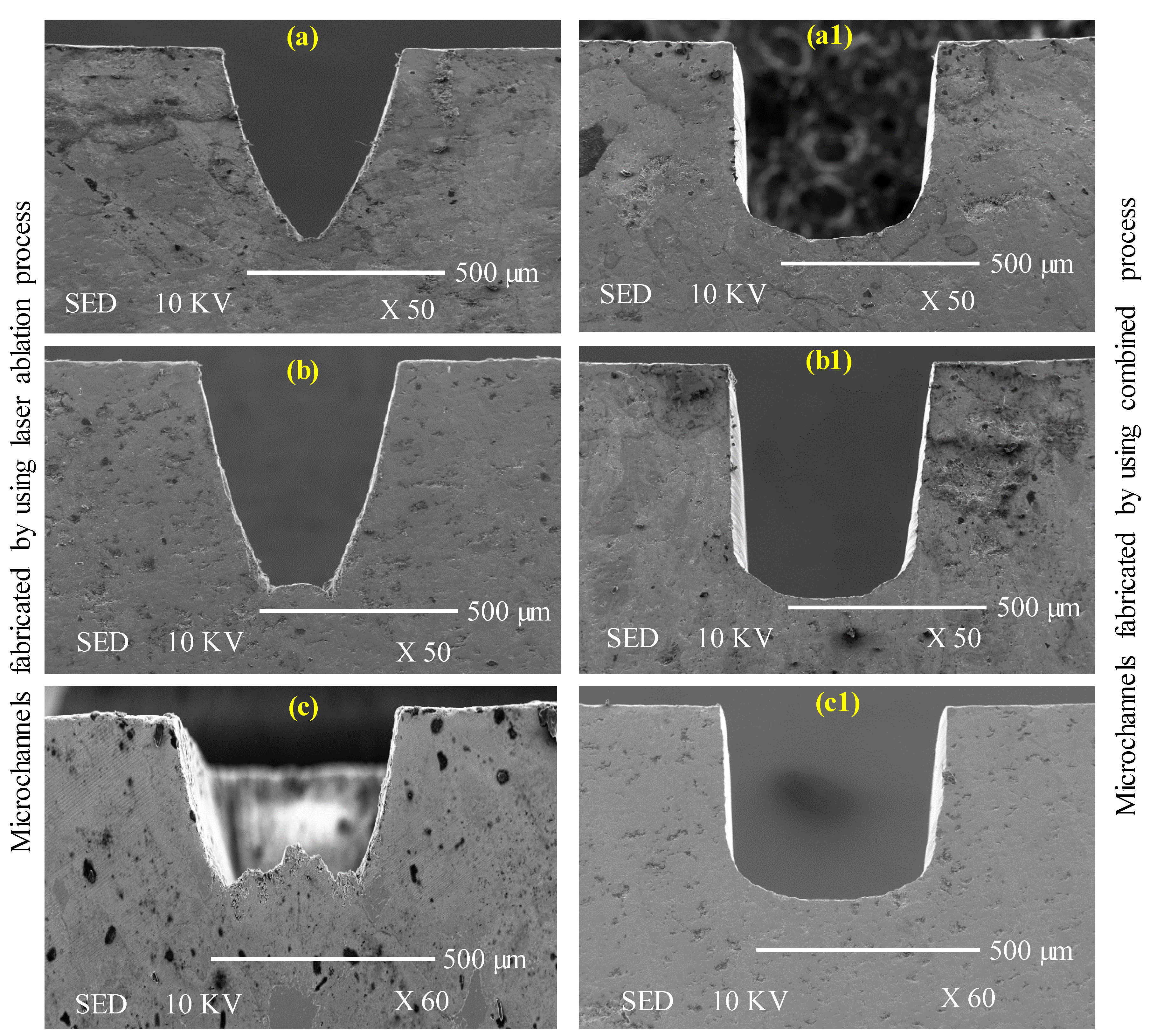
The illustration of cross-sections of channels obtained through the LBM and LRUM processes is provided in Figure 14. The cross-sections accomplished by the LRUM process correctly approximate the rectangular or square cross-section as perceived in the design phase. However, cross-sections manufactured by LBM have deviated significantly from their actual representation. As shown in Figure 14, the channel cross-section ended up taking the form of a conical or tapered cross-section rather than a rectangular or square cross-section. It implies the bottom width produced in LBM is smaller than expected. This can be due to the inherent characteristics of the laser that it imparts some taper as the machining depth progresses [45]. Certainly, the LBM could not machine or transfer the necessary energy to maintain the channel’s dimensional accuracy according to the expected one. LRUM has overcome this deficiency of LBM through RUM to precisely generate the required channel cross-sections.

3.3. Machining Time

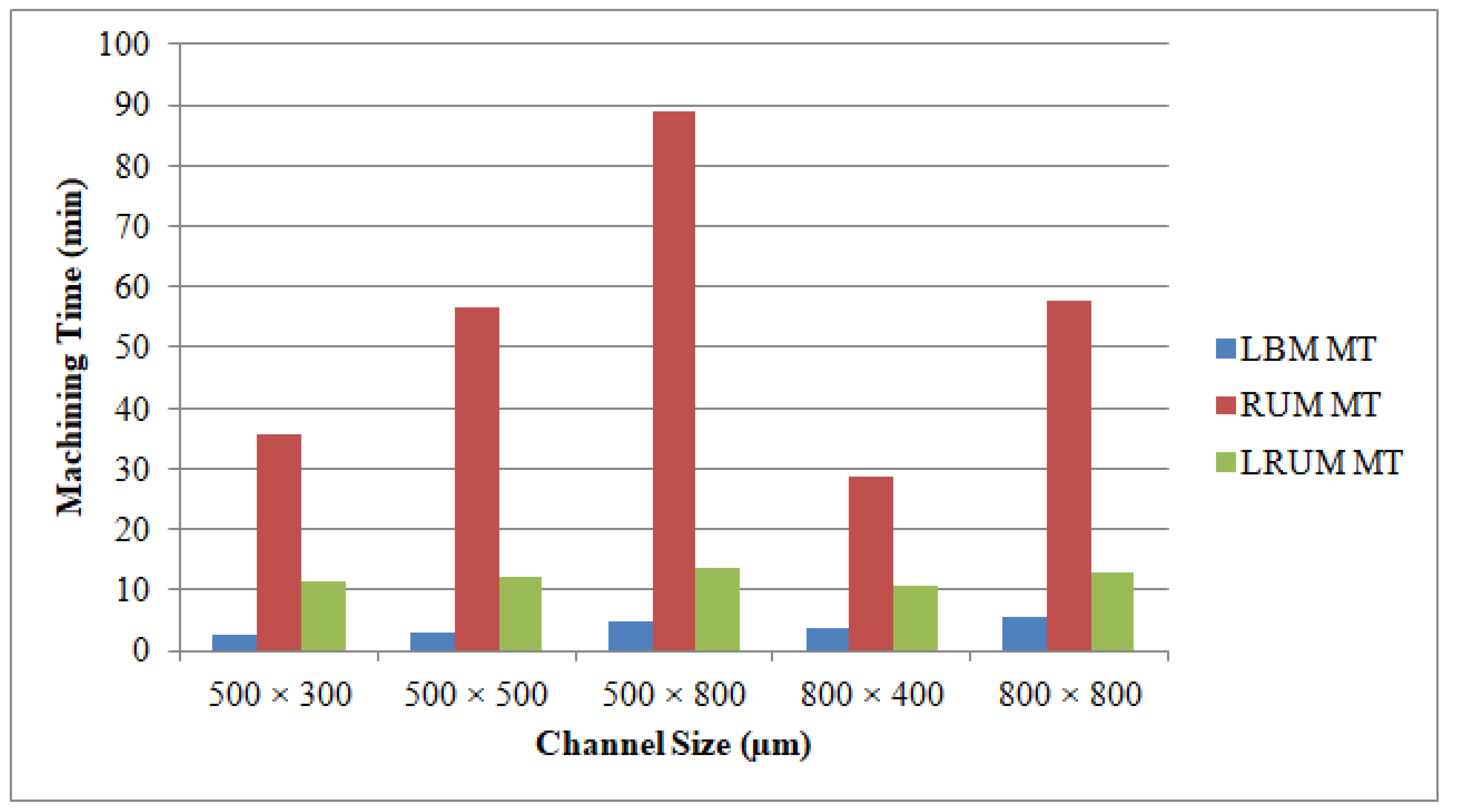
In most machining practices, MT is among the most important considerations, because it regulates overall machining costs. In the LBM method, laser intensity and laser scanning speed are the key drivers impacting the MT at a constant layer thickness. Furthermore, the feed rate and depth of cut are the most major factors influencing the MT in RUM. Figure 15 shows the outcomes of the mean MT for various channels produced using LBM, RUM, and LRUM methods.
The LBM process contributes to the least MT amongst the three machining technologies that were deployed. Even though the LRUM process produced a higher MT relative to the LBM process, it is substantially superior in terms of MT as opposed to RUM. For instance, in the LRUM procedure, the MT decreases from 84.9 min (in RUM) to 12.7 min. The selected channel widths are equal to the outer diameters of the RUM tool in the RUM process. The 800 μm tool diameter is more robust than the 500 μm tool and depending on RUM’s optimum process parameters the selected feed rate and cutting depth are greater than those of the small size tool (500 μm diameter). Therefore, the MT for the channel sizes of 800 µm × 400 µm (26.8 min) and 800 µm × 800 µm (53.4 min) are smaller than 500 µm × 300 µm (3.8 min) and 500 µm × 800 µm (84.9 min) respectively. The percentage of changes made in the MT by using the LRUM process as opposed to the RUM process’s MT can be observed in Figure 16.

3.4. Tool Wear

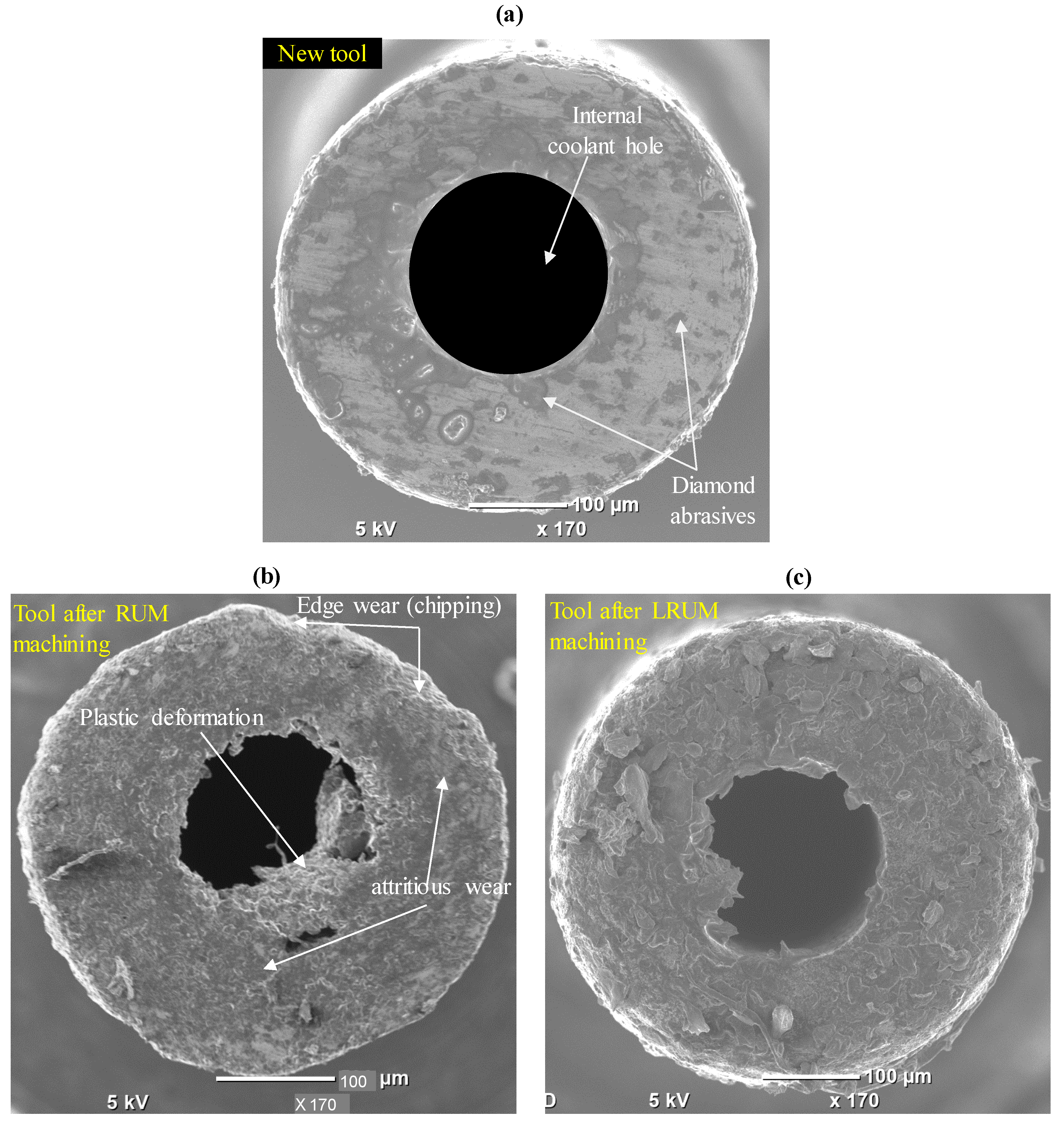
The comparisons of the new RUM tool, the tool after machining twelve channels by using RUM, and the tool used for finishing twelve channels by using LRUM processes are depicted in Figure 17. Figure 17a provides the end-cutting-face perspective of the new tool, in which the diamond abrasives and bonding material can be easily viewed. It implies that the tool exhibits uniform inner and outer radii as well as a fairly sharp cutting edge. The end cutting edge of the tool used in the LRUM process is shown in Figure 17b in which attritions wear, edge chipping, and rounding of tools can be observed, and these wear mechanisms have also been documented in [67,68]. In addition, it is clear in Figure 17b that, due to the increased pressure on the tool end face during machining, some of the tool bonding material along with the diamond abrasive are plastically deformed and dragged through the coolant hole. Such tool wear can adversely affect the coolant efficiency of the tool owing to the coolant passage obstruction. Figure 17c shows the end cutting edge of the tool used for finishing twelve channels by using the LRUM process. It can be noted that there is a minimal rounded edge and less plastic deformation during machining under the LRUM process. It must be mentioned that the length of the tool is recalibrated by the integrated DMG laser tool length calibration device after every microchannel is machined.

4. Conclusions

Microchannels of varying sizes were manufactured in biolox forte ceramic material using LBM, RUM, and LRUM processes at their optimal parameters. The MT is far lower during LBM but the performance of the microchannels is not reasonable in terms of surface finish, surface morphology, and dimensional precision. However on the other side, the surface quality and dimensional accuracy of the RUM-produced microchannels are indeed very high, but it is a slower process because the MT is very high. To solve these issues and maximize the benefits of both the machining processes (less MT of LBM in addition to higher surface quality and dimensional accuracy of RUM), a new combined machining process is introduced, known as the LRUM process. The microchannels are initially machined using LBM in LRUM, where much of the material is extracted and after which the exact microchannels are completed with RUM. While using LRUM the surface quality has been improved in terms of both surface roughness and surface morphology for microchannels of different sizes compared to LBM findings. The Ra values are reduced by more than 88 percent for all sizes of generated microchannels. It is also reported that in some channel sizes the DE and WE values are also decreased by 70% and 80% respectively. Moreover, the MT of RUM is reduced by 85% with the execution of LRUM, particularly in the channels with greater depth (size of 500 µm width × 800 µm depth). The tool wear is also found to be reduced while using combined LRUM as compared to the tool wear resulting from RUM under the same machining conditions. Certainly, the overall machining cost is reduced considerably with the application of LRUM.

Author Contributions

B.M.A.A. conceived the idea, designed and performed the experiments, and wrote the paper; B.M.A.A. and S.H.M. analyzed the data and edited the paper; A.E.-T. supervised and provided critical advices on the research strategy; H.A. and K.M. project administration, revision, and funding acquisition. All authors have read and agreed to the published version of the manuscript.

Funding

This research was financially supported by the Deanship of Scientific Research, King Saud University: Research group no. (RG-1441-349).

Acknowledgments

The authors extend their appreciation to the Deanship of Scientific Research at King Saud University for funding this work through research group no. (RG-1441-349).

Conflicts of Interest

The authors have no conflict of interest to declare.

References

  1. Schneider, F.; Das, J.; Kirsch, B.; Linke, B.; Aurich, J.C. Sustainability in ultra precision and micro machining: A review. Int. J. Precis. Eng. Manuf. Green Technol. 2019, 6, 601–610. [Google Scholar] [CrossRef] [Green Version]
  2. Hasan, M.; Zhao, J.; Jiang, Z. Micromanufacturing of composite materials: A review. Int. J. Extrem. Manuf. 2019, 1, 012004. [Google Scholar] [CrossRef]
  3. Ruggeri, S.; Fontana, G.; Fassi, I. Micro-assembly. In Micro-Manufacturing Technologies and Their Applications; Springer: Berlin, Germany, 2017. [Google Scholar] [CrossRef]
  4. Fallahi, H.; Zhang, J.; Phan, H.P.; Nguyen, N.T. Flexible microfluidics: Fundamentals, recent developments, and applications. Micromachines 2019, 10, 830. [Google Scholar] [CrossRef] [PubMed] [Green Version]
  5. Ahmed, N.; Darwish, S.; Alahmari, A.M. Laser ablation and laser-hybrid ablation processes: A review. Mater. Manuf. Process. 2016, 31, 1121–1142. [Google Scholar] [CrossRef]
  6. Cheng, C.; Tsai, X.; Chen, J. Micromachining of stainless steel with controllable ablation depth using femtosecond laser pulses. Int. J. Adv. Manuf. Technol. 2016, 1947–1954. [Google Scholar] [CrossRef]
  7. Sunderlal, S.; Kr, P.; Khare, A.; Joshi, S.N. Effect of laser beam conditioning on fabrication of clean micro-channel on stainless steel 316L using second harmonic of Q-switched Nd: YAG laser. Opt. Laser Technol. 2018, 99, 107–117. [Google Scholar] [CrossRef]
  8. Tangwarodomnukun, V.; Wuttisarn, T. Evolution of milled cavity in the multiple laser scans of titanium alloy under a flowing water layer. Int. J. Adv. Manuf. Technol. 2017, 92, 293–302. [Google Scholar] [CrossRef]
  9. Darwish, S.; Ahmed, N.; Alahmari, A.M. A study of micro-channel size and spatter dispersion for laser beam micro-milling. Mater. Manuf. Process. 2017, 32, 171–184. [Google Scholar] [CrossRef]
  10. Chen, J.; Zhou, X.; Lin, S.; Tu, Y. A prediction-correction scheme for microchannel milling using femtosecond laser. Opt. Lasers Eng. 2017, 91, 115–123. [Google Scholar] [CrossRef]
  11. Teixidor, D.; Orozco, F. Effect of process parameters in nanosecond pulsed laser micromachining of PMMA-based microchannels at near-infrared and ultraviolet wavelengths. Int. J. Adv. Manuf. Technol. 2013, 67, 1651–1664. [Google Scholar] [CrossRef]
  12. Prakash, S.; Kumar, S. Experimental investigations and analytical modeling of multi-pass CO2 laser processing on PMMA. Precis. Eng. 2017, 49, 220–234. [Google Scholar] [CrossRef]
  13. Mccann, R.; Bagga, K.; Groarke, R.; Stalcup, A. Microchannel fabrication on cyclic olefin polymer substrates via 1064 nm Nd: YAG laser ablation. Appl. Surf. Sci. 2016, 387, 603–608. [Google Scholar] [CrossRef] [Green Version]
  14. Prakash, S.; Kumar, S. Fabrication of microchannels on transparent PMMA using CO2 laser (10.6 µm) for microfluidic applications: An experimental investigation. Int. J. Precis. Eng. Manuf. 2015, 16, 361–366. [Google Scholar] [CrossRef]
  15. Nieto, D.; Delgado, T.; Flores-arias, M.T. Fabrication of microchannels on soda-lime glass substrates with a Nd: YVO4 laser. Opt. Lasers Eng. 2014, 63, 11–18. [Google Scholar] [CrossRef]
  16. Bulushev, E.; Bessmeltsev, V.; Dostovalov, A.; Goloshevsky, N.; Wolf, A. High-speed and crack-free direct-writing of microchannels on glass by an IR femtosecond laser. Opt. Lasers Eng. 2016, 79, 39–47. [Google Scholar] [CrossRef]
  17. Chang, T.; Chen, Z.; Lee, Y.; Li, Y.; Wang, C. Ultrafast laser ablation of soda-lime glass for fabricating micro fl uidic pillar array channels. Microelectron. Eng. 2016, 158, 95–101. [Google Scholar] [CrossRef]
  18. Liu, Y.; Liu, L.; Deng, J.; Meng, R.; Zou, X.; Wu, F. Fabrication of micro-scale textured grooves on green ZrO2 ceramics by pulsed laser ablation. Ceram. Int. 2017, 43, 6519–6531. [Google Scholar] [CrossRef]
  19. Garcia-Giron, A.; Sola, D.; Pena, J.I. Liquid-assisted laser ablation of advanced ceramics and glass-ceramic materials. Appl. Surf. Sci. 2016, 363, 548–554. [Google Scholar] [CrossRef]
  20. Zhang, Y.; Wang, Y.; Zhang, J.; Liu, Y.; Yang, X.; Zhang, Q. Micromachining features of TiC ceramic by femtosecond pulsed laser. Ceram. Int. 2015, 41, 6525–6533. [Google Scholar] [CrossRef]
  21. Adelmann, B.; Hellmann, R. Rapid micro hole laser drilling in ceramic substrates using single mode fiber laser. J. Mater. Process. Technol. 2015, 221, 80–86. [Google Scholar] [CrossRef]
  22. Zhang, J.; Long, Y.; Liao, S.; Lin, H.T.; Wang, C. Effect of laser scanning speed on geometrical features of Nd:YAG laser machined holes in thin silicon nitride substrate. Ceram. Int. 2017, 43, 2938–2942. [Google Scholar] [CrossRef]
  23. Leitz, K.H.; Redlingshöer, B.; Reg, Y.; Otto, A.; Schmidt, M. Metal ablation with short and ultrashort laser pulses. Phys. Procedia 2011, 12, 230–238. [Google Scholar] [CrossRef] [Green Version]
  24. Gaudiuso, C.; Volpe, A.; Ancona, A. One-step femtosecond laser stealth dicing of quartz. Micromachines 2020, 11, 327. [Google Scholar] [CrossRef] [PubMed] [Green Version]
  25. Oosterbeek, R.N.; Ward, T.; Corazza, C.; Bodley, O.; Ashforth, S.; Rodda, A.; Simpson, M.C. Fast femtosecond laser ablation for efficient cutting of sintered alumina and quartz substrates. In Proceedings of the 2016 Conference on Lasers Electro-Optics, San Jose, CA, USA, 5–10 June 2016; pp. 1–13. [Google Scholar] [CrossRef]
  26. Olbrich, M.; Punzel, E.; Lickschat, P.; Weißmantel, S.; Horn, A. Investigation on the ablation of thin metal films with femtosecond to picosecond-pulsed laser radiation. Phys. Procedia 2016, 83, 93–103. [Google Scholar] [CrossRef] [Green Version]
  27. Kataria, R.; Kumar, J. Ultrasonic machining: A review. Adv. Mater. Res. 2016, 1137, 61–78. [Google Scholar] [CrossRef]
  28. Li, Z.; Yuan, S.; Zhang, C. Research on the rotary ultrasonic facing milling of ceramic matrix composites. Procedia CIRP 2016, 56, 428–433. [Google Scholar] [CrossRef] [Green Version]
  29. Abdo, B.M.A.; El-tamimi, A.; Nasr, E.A. Rotary ultrasonic machining of alumina ceramic: An experimental investigation of tool path and tool overlapping. Appl. Sci. 2020, 10, 1667. [Google Scholar] [CrossRef] [Green Version]
  30. Sreehari, D.; Kumar, A. On form accuracy and surface roughness in micro-ultrasonic machining of silicon microchannels. Precis. Eng. 2018, 53, 300–309. [Google Scholar] [CrossRef]
  31. Ning, F.; Wang, H.; Hu, Y.; Cong, W.; Zhang, M.; Li, Y. Rotary ultrasonic surface machining of CFRP composites: A comparison with conventional surface grinding. Procedia Manuf. 2017, 10, 557–567. [Google Scholar] [CrossRef]
  32. Lv, D.; Huang, Y.; Wang, H.; Tang, Y.; Wu, X. Improvement effects of vibration on cutting force in rotary ultrasonic machining of BK7 glass. J. Mater. Process. Technol. 2013, 213, 1548–1557. [Google Scholar] [CrossRef]
  33. Fernando, P.; Zhang, M.; Pei, Z.; Cong, W. Intermittent and continuous rotary ultrasonic machining of K9 glass: An experimental investigation. J. Manuf. Mater. Process. 2017, 1, 20. [Google Scholar] [CrossRef] [Green Version]
  34. Wang, Q.; Cong, W.; Pei, Z.J.; Gao, H.; Kang, R. Rotary ultrasonic machining of potassium dihydrogen phosphate (KDP) crystal: An experimental investigation on surface roughness. J. Manuf. Process. 2009, 11, 66–73. [Google Scholar] [CrossRef]
  35. Jiao, Y.; Hu, P.; Pei, Z.J.; Treadwell, C. Rotary ultrasonic machining of ceramics: Design of experiments. Int. J. Manuf. Technol. Manag. 2005, 7, 192–206. [Google Scholar] [CrossRef]
  36. Singh, R.P.; Singhal, S.; Singh, R.P.; Singhal, S. Rotary ultrasonic machining: A review. Mater. Manuf. Process. 2017, 31, 1795–1824. [Google Scholar] [CrossRef]
  37. Thoe, T.B. Review on ultrasonic machining. Int. J. Mach. Tools Manuf. 1998, 38, 239–255. [Google Scholar] [CrossRef]
  38. Unune, D.R.; Mali, H.S. Current status and applications of hybrid micro-machining processes: A review. Proc. Inst. Mech. Eng. Part B J. Eng. Manuf. 2015, 229, 1681–1693. [Google Scholar] [CrossRef]
  39. Singh, R.; Melkote, S.N. Characterization of a hybrid laser-assisted mechanical micromachining (LAMM) process for a difficult-to-machine material. Int. J. Mach. Tools Manuf. 2007, 47, 1139–1150. [Google Scholar] [CrossRef]
  40. Fortunato, A.; Guerrini, G.; Melkote, S.N.; Bruzzone, A.A.G. A laser assisted hybrid process chain for high removal rate machining of sintered silicon nitride. CIRP Ann. Manuf. Technol. 2015, 64, 189–192. [Google Scholar] [CrossRef]
  41. Tangwarodomnukun, V.; Wang, J.; Huang, C.Z.; Zhu, H.T. Heating and material removal process in hybrid laser-waterjet ablation of silicon substrates. Int. J. Mach. Tools Manuf. 2014, 79, 1–16. [Google Scholar] [CrossRef]
  42. Al-Ahmari, A.M.A.; Rasheed, M.S.; Mohammed, M.K.; Saleh, T. A hybrid machining process combining micro-EDM and laser beam machining of nickel-titanium-based shape memory alloy. Mater. Manuf. Process. 2016, 31, 447–455. [Google Scholar] [CrossRef]
  43. Kizaki, T.; Ito, Y.; Tanabe, S.; Kim, Y.; Sugita, N.; Mitsuishi, M. Laser-assisted machining of zirconia ceramics using a diamond bur. Procedia CIRP 2016, 42, 497–502. [Google Scholar] [CrossRef]
  44. Trotta, G.; Vázquez, R.M.; Volpe, A.; Modica, F.; Ancona, A.; Fassi, I.; Osellame, R. Disposable optical stretcher fabricated by microinjection moulding. Micromachines 2018, 9, 388. [Google Scholar] [CrossRef] [PubMed] [Green Version]
  45. Abdo, B.M.A.; Anwar, S.; El-Tamimi, A.M.; Alahmari, A.M.; Abouel Nasr, E. Laser micro-milling of bio-lox forte ceramic: An experimental analysis. Precis. Eng. 2018, 53, 179–193. [Google Scholar] [CrossRef]
  46. Samant, A.N.; Dahotre, N.B. Laser machining of structural ceramics—A review. J. Eur. Ceram. Soc. 2009, 29, 969–993. [Google Scholar] [CrossRef]
  47. Leone, C.; Genna, S.; Tagliaferri, F.; Palumbo, B.; Dix, M. Experimental investigation on laser milling of aluminium oxide using a 30 W Q-switched Yb: YAG fiber laser. Opt. Laser Technol. 2016, 76, 127–137. [Google Scholar] [CrossRef]
  48. Singh, R.P.; Singhal, S. Investigation of machining characteristics in rotary ultrasonic machining of alumina ceramic. Mater. Manuf. Process. 2017, 32, 309–326. [Google Scholar] [CrossRef]
  49. Maccauro, G.; Iommetti, P.R.; Manicone, P.F.; Raffaelli, L. Zirconia and Alumina Bioceramic Biocompatibility; Nova Science Publishers Inc.: Hauppauge, NY, USA, 2012; Available online: https://www.scopus.com/inward/record.uri?eid=2-s2.0-84892057573&partnerID=40&md5=38ef11eb8bf1e7387699a8666ab9570d (accessed on 20 November 2019).
  50. CeramTec—The Ceramic Experts. Available online: https://www.ceramtec.com/ (accessed on 17 March 2020).
  51. Whitesides, G.M. The origins and the future of microfluidics. Nature 2006, 442, 368–373. [Google Scholar] [CrossRef]
  52. Farhan Shafique, M.; Laister, A.; Clark, M.; Miles, R.E.; Robertson, I.D. Fabrication of embedded microfluidic channels in low temperature co-fired ceramic technology using laser machining and progressive lamination. J. Eur. Ceram. Soc. 2011, 31, 2199–2204. [Google Scholar] [CrossRef]
  53. Ong, S.E.; Zhang, S.; Du, H.J.; Fu, Y.Q. Fundamental principles and applications of microfluidic systems. Front. Biosci. 2008, 13, 2757–2773. [Google Scholar] [CrossRef] [Green Version]
  54. Guarino, S.; Ponticelli, G.S.; Giannini, O.; Genna, S.; Trovalusci, F. Laser milling of yttria-stabilized zirconia by using a Q-switched Yb: YAG fiber laser: Experimental analysis. Int. J. Adv. Manuf. Technol. 2017, 94, 1373–1385. [Google Scholar] [CrossRef]
  55. Li, J.; Ji, L.; Hu, Y.; Bao, Y. Precise micromachining of yttria-tetragonal zirconia polycrystal ceramic using 532 nm nanosecond laser. Ceram. Int. 2016, 42, 4377–4385. [Google Scholar] [CrossRef]
  56. Abdo, B.M.A.; Ahmed, N.; El-Tamimi, A.M.; Anwar, S.; Alkhalefah, H.; Nasr, E.A. Laser beam machining of zirconia ceramic: An investigation of micro-machining geometry and surface roughness. J. Mech. Sci. Technol. 2019, 33, 1817–1831. [Google Scholar] [CrossRef]
  57. Abdo, B.M.A.; El-Tamimi, A.M.; Anwar, S.; Umer, U.; Alahmari, A.M.; Ghaleb, M.A. Experimental investigation and multi-objective optimization of Nd:YAG laser micro-channeling process of zirconia dental ceramic. Int. J. Adv. Manuf. Technol. 2018, 98, 1–18. [Google Scholar] [CrossRef]
  58. Wang, J.; Shimada, K.; Mizutani, M.; Kuriyagawa, T. Effects of abrasive material and particle shape on machining performance in micro ultrasonic machining. Precis. Eng. 2018, 51, 373–387. [Google Scholar] [CrossRef]
  59. Sandeep, K.; Akshay, D. Fabrication of microchannels using rotary tool micro-USM: An experimental investigation on tool wear reduction and form accuracy improvement. J. Manuf. Process. 2018, 32, 802–815. [Google Scholar] [CrossRef]
  60. Jain, A.K.; Pandey, P.M. Experimental studies on tool wear in μ-RUM process. Int. J. Adv. Manuf. Technol. 2016, 85, 2125–2138. [Google Scholar] [CrossRef]
  61. Abdo, B.M.A.; Anwar, S.; El-tamimi, A.M.; Nasr, E.A. Experimental analysis on the influence and optimization of µ-RUM parameters in machining alumina bioceramic. Materials 2019, 12, 616. [Google Scholar] [CrossRef] [Green Version]
  62. Abdo, B.M.A.; Anwar, S.; El-tamimi, A. Machinability study of biolox forte ceramic by milling microchannels using rotary ultrasonic machining. J. Manuf. Process. 2019, 43, 175–191. [Google Scholar] [CrossRef]
  63. Prakash, S.; Kumar, S. Fabrication of rectangular cross-sectional microchannels on PMMA with a CO2 laser and underwater fabricated copper mask. Opt. Laser Technol. 2017, 94, 180–192. [Google Scholar] [CrossRef]
  64. Umer, U.; Khan, M.; Al-ahmari, A. Multi-response optimization of machining parameters in micro milling of alumina ceramics using Nd: YAG laser. Measurement 2017, 95, 181–192. [Google Scholar] [CrossRef]
  65. Gupta, K.; Gupta, M.K. Developments in nonconventional machining for sustainable production: A state-of-the-art review. Proc. Inst. Mech. Eng. Part C J. Mech. Eng. Sci. 2019, 233, 4213–4232. [Google Scholar] [CrossRef]
  66. Holmberg, J.; Berglund, J.; Wretland, A.; Beno, T. Evaluation of surface integrity after high energy machining with EDM, laser beam machining and abrasive water jet machining of alloy 718. Int. J. Adv. Manuf. Technol. 2019, 100, 1575–1591. [Google Scholar] [CrossRef] [Green Version]
  67. Kuriakose, S.; Patowari, P.K.; Bhatt, J. Machinability study of Zr-Cu-Ti metallic glass by micro hole drilling using micro-USM. J. Mater. Process. Technol. 2017, 240, 42–51. [Google Scholar] [CrossRef]
  68. Cheema, M.S.; Singh, P.K.; Tyagi, O.; Dvivedi, A.; Sharma, A.K. Tool wear and form accuracy in ultrasonically machined microchannels. Meas. J. Int. Meas. Confed. 2016, 81, 85–94. [Google Scholar] [CrossRef]
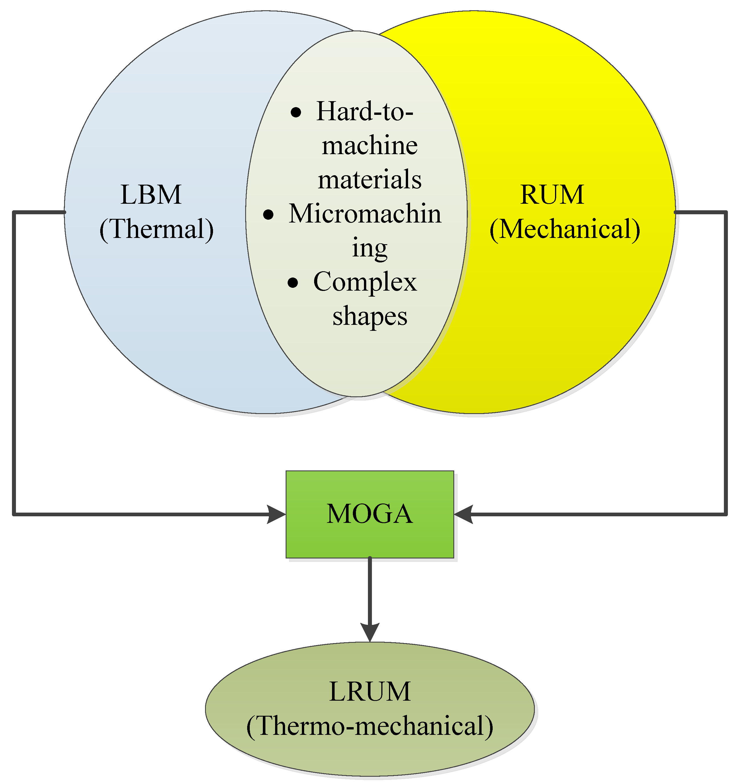
Figure 1. Unification of laser beam machining (LBM), rotary ultrasonic machining (RUM), and laser rotary ultrasonic machining (LRUM) processes.
Materials 13 03505 g001
Figure 2. (a) Lasertec 40 machine, (b) schematic diagram of the laser system machine.
Materials 13 03505 g002
Figure 3. (a) Ultrasonic 20 Linear machine, (b) MicroRUM tool; (c) Schematic diagram of RUM.
Materials 13 03505 g003
Figure 4. Schematic of microchannel.
Materials 13 03505 g004
Figure 5. Workflow adopted in this study.
Materials 13 03505 g005
Figure 6. LRUM setup: (a) setup of workpiece leveling, (b) setup of tool alignment.
Materials 13 03505 g006
Figure 7. Measurement equipment: (a) optical microscope, (b) 3D profilometer, (c) SEM.
Materials 13 03505 g007
Figure 8. Samples of microchannels fabricated under the optimal conditions of LBM and LRUM.
Materials 13 03505 g008
Figure 9. Results of surface roughness of the fabricated channels by using LBM, RUM, and combined LRUM processes.
Materials 13 03505 g009
Figure 10. Percentage of improvement in the surface roughness of the fabricated channels by using LRUM comparing to LBM.
Materials 13 03505 g010
Figure 11. Comparison of the surface morphology of the fabricated channels by using LRUM comparing to LBM, (a,b) channels’ bed, (c,d) channels’ side.
Materials 13 03505 g011
Figure 12. Results of dimensional errors of the fabricated channels by using LBM, RUM, and combined LRUM processes. DE and WE: dimensional errors.
Materials 13 03505 g012
Figure 13. Percentage of improvement in the dimensional accuracy of the fabricated channels by using LRUM comparing to LBM.
Materials 13 03505 g013
Figure 14. Comparison of the cross-sections of the fabricated channels by using LBM and combined LRUM processes: (ac): cross-sections of the microchannels machined by using LBM process; (a1c1): cross-sections of the microchannels machined by using LRUM combined process.
Materials 13 03505 g014
Figure 15. Results of the machining time (MT) of the fabricated channels by using LBM, RUM, and combined LRUM processes.
Materials 13 03505 g015
Figure 16. Percentage of improvement in the MT of the fabricated channels by using LRUM comparing to RUM.
Materials 13 03505 g016
Figure 17. Comparison of the RUM tool (a) before machining (new tool), (b) after machining by using RUM, (c) after machining by using LRUM.
Materials 13 03505 g017
Table 1. Mechanical and thermal properties of biolox forte.
PropertyValue (Unit)
Fracture toughness3.3 (MPa·m1/2)
Compressive strength5500 (MPa)
Tensile strength665 (MPa)
Bulk density3.98 (g/cm3)
Poisson’s ratio0.22–0.25
Vickers hardness1900 (HV 1)
Young’s modulus413 (GPa)
Thermal conductivity 20 °C30 (W/mK)
Thermal expansion coefficient5.4 (10−6 1/K)
Melting point2277 (°F)
Table 2. Dimensional specification of microchannels used in this study.
Cross-SectionsChannel Size (µm)
DepthWidth
Rectangular500300
500800
800400
Square500500
800800
Table 3. LBM and RUM parameters and their respective levels.
LBM Input ParametersRangeRUM Input ParametersLevels
Laser intensity88%–96%Spindle speed2000–7000 rpm
Scanning speed100–400 mm/sFeed rate0.4–1 mm/min
Pulse frequency5–12 kHzDepth of cut0.025–0.1 mm
Layer thickness2 µmVibration amplitude5–25 µm
Track displacement10 µmVibration frequency20–32 kHz
Table 4. MOGA parameters used in this study.
ParameterValue
Number of generations100
Probability of direction cross-over0.5
Probability of selection0.05
Probability of mutation0.1
DNA string mutation ratio0.05
Random generator seed1