Experimental Studies of Concrete-Filled Composite Tubes under Axial Short- and Long-Term Loads


Abstract
1. Introduction
1.1. Concrete-Filled Fiber Reinforced Polymer (FRP) Tubes (CFFT) Column Concept
1.2. Examples of Applications of CFFT Columns in Engineering Construction
2. Materials and Methods of Experimental Studies on CFFT Columns
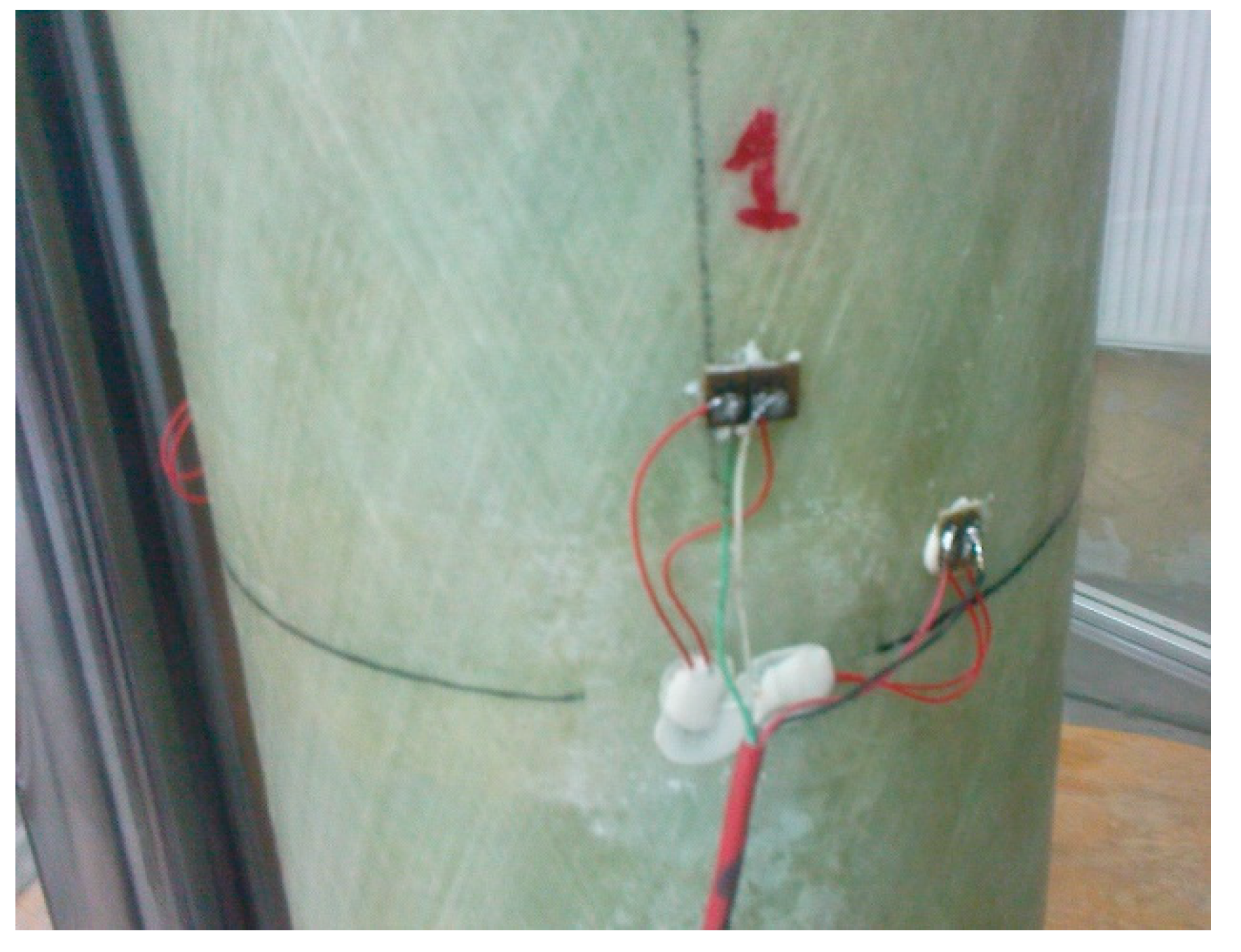
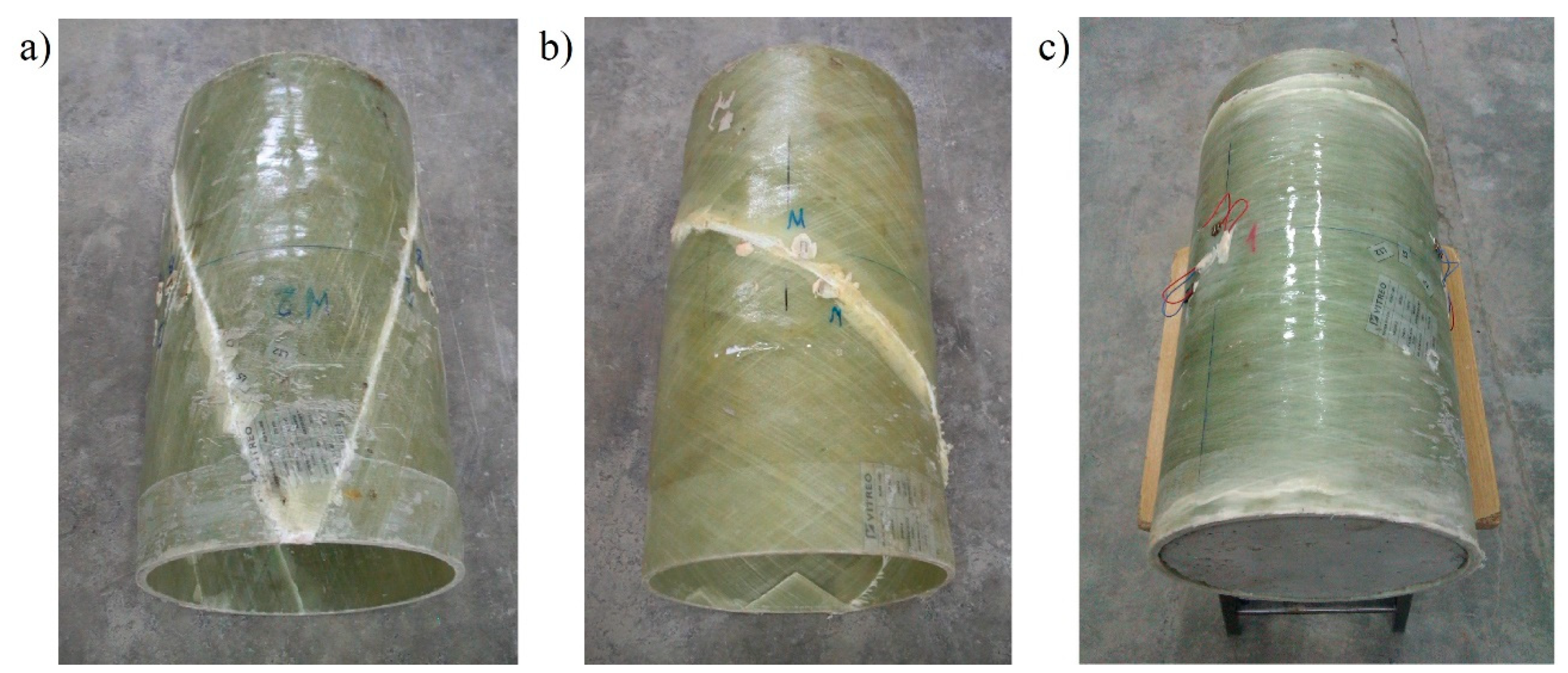
2.1. Composite Pipes
2.1.1. Geometric and Technological Parameters of Pipes
2.1.2. Longitudinal Compression Strength of Pipe Composite
2.1.3. Elasticity Modulus and Ultimate Strains of Pipe Composite in Longitudinal Compression
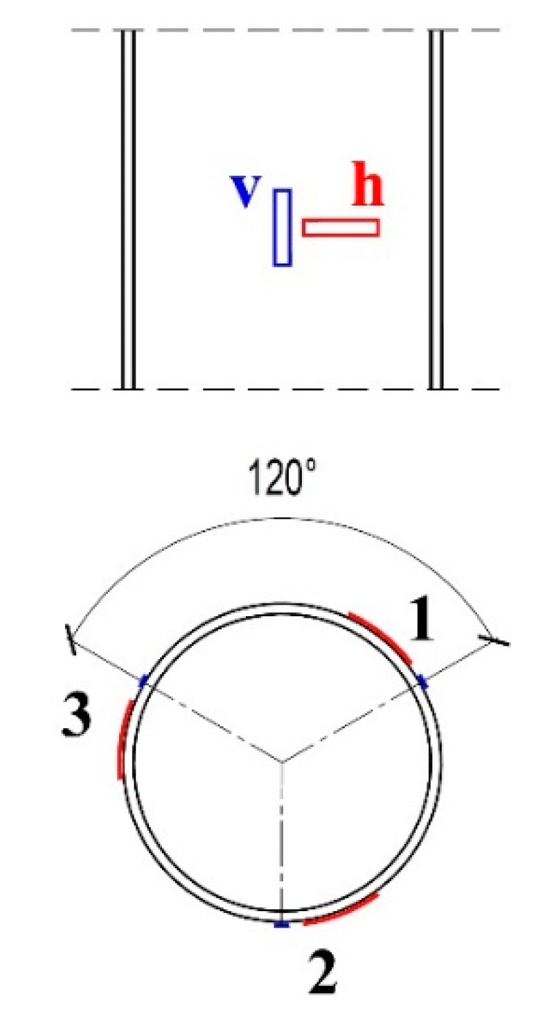
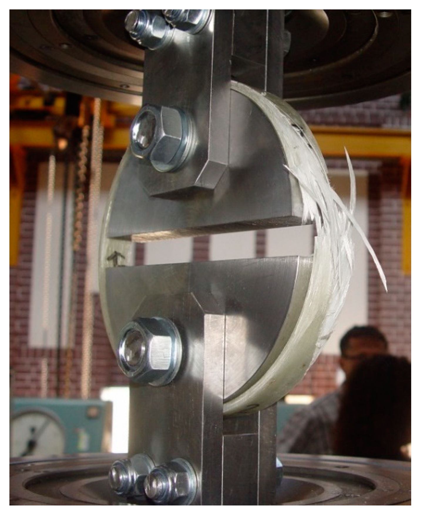
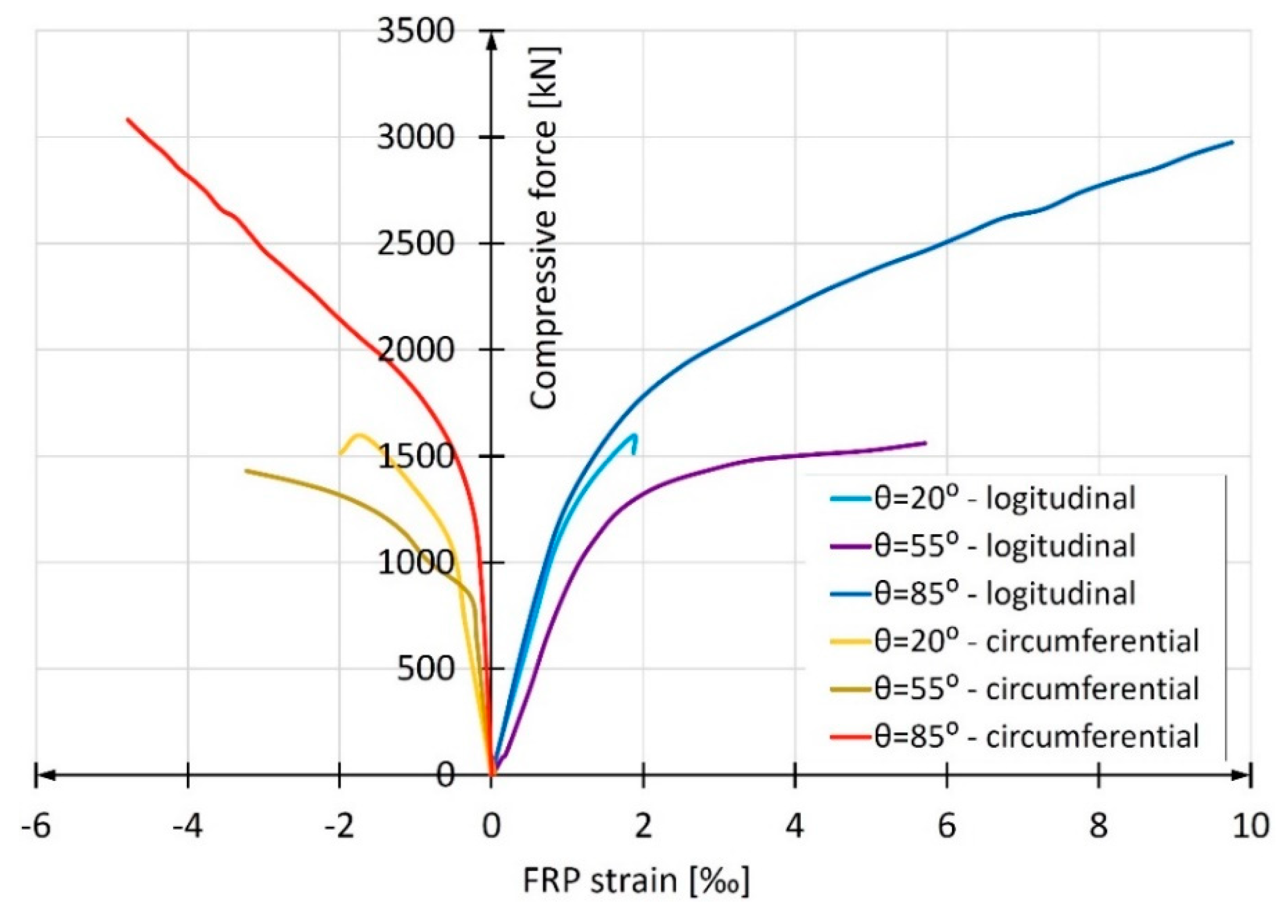
2.1.4. Circumferential Tensile Strength of Composite Tubes and Modulus of Elasticity at Circumferential Stress
2.2. Concrete Filling Composite Tubes
3. Results of the Experimental Studies on Concrete-Filled Tubular Columns
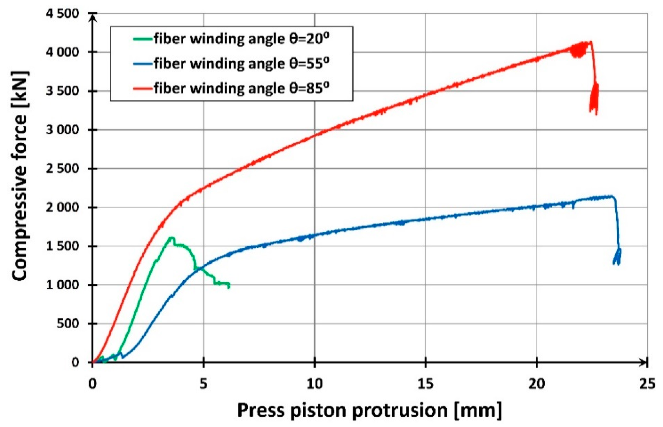
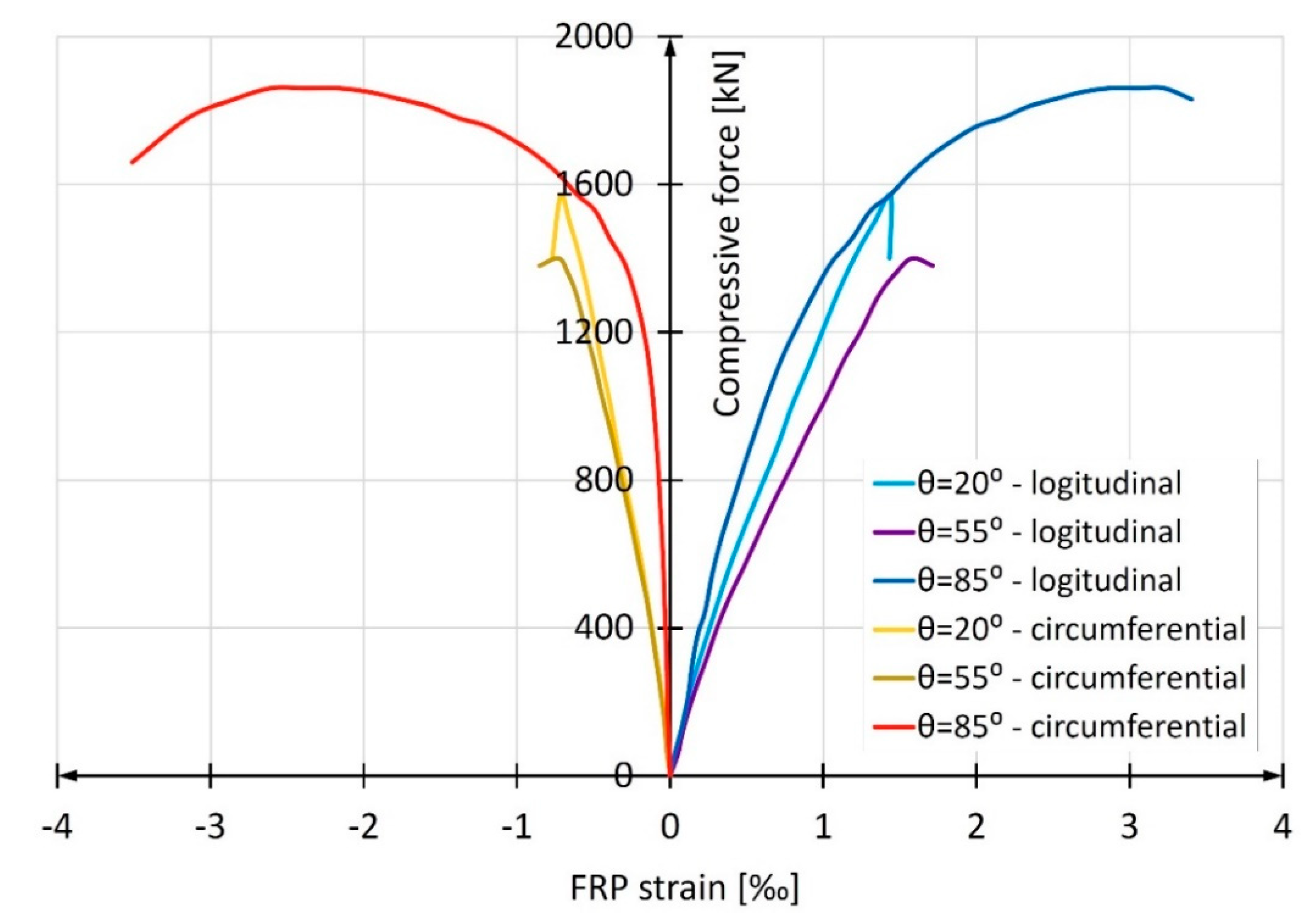
3.1. Short Columns
3.2. Long Columns
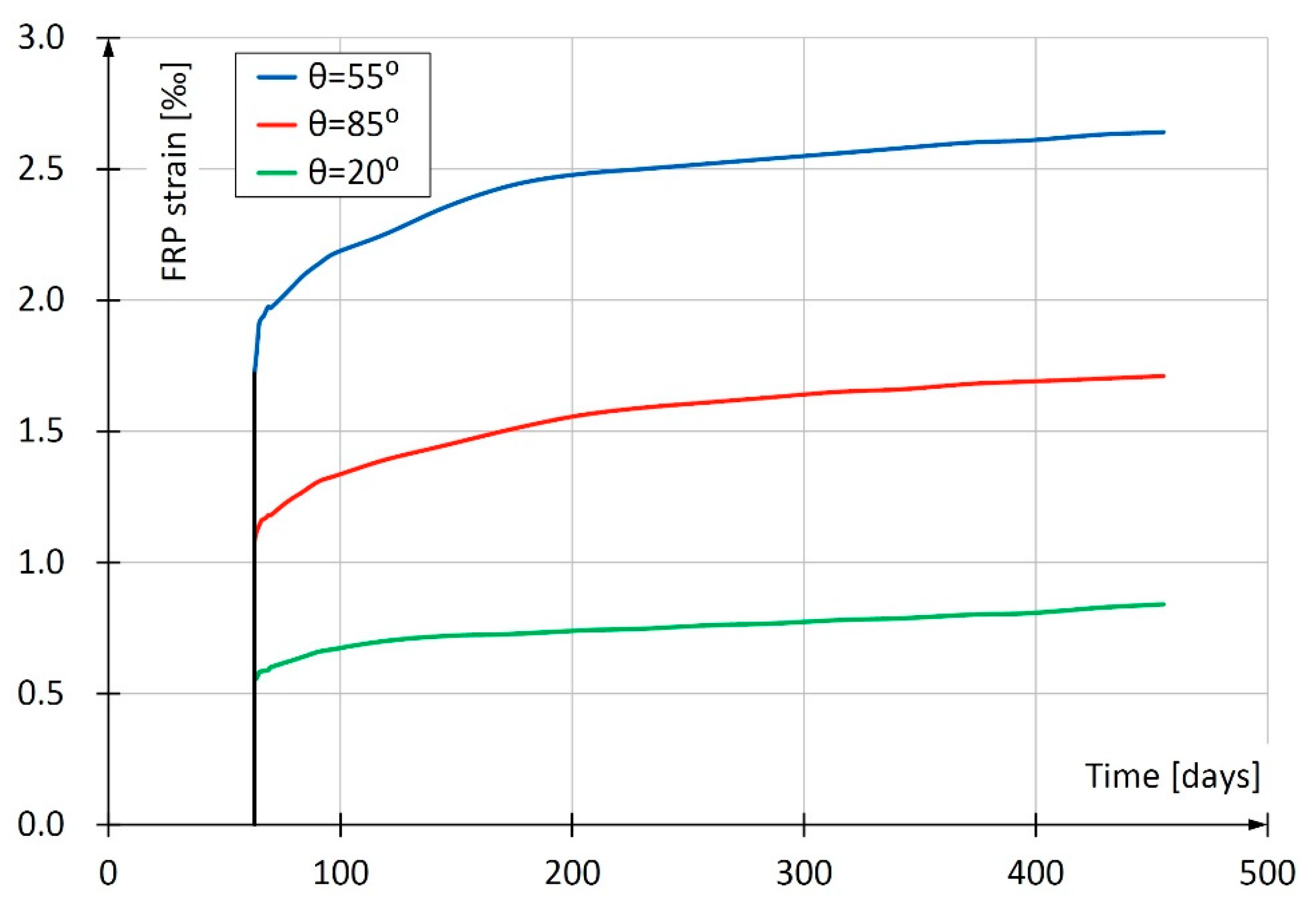
3.3. Long-Term Studies
4. Conclusions
- columns made of FRP pipes filled with concrete (concrete-filled FRP tubes, (CFFT)) behave in a way that depends on the direction of fiber winding in the pipe;
- the load-bearing capacity of the CFFT columns is highest when the fibers are wound in a circumferential direction;
- the difference in load-bearing capacity caused by the direction of the fiber winding can be very large for stub columns and reach more than 150%;
- for slender columns used in the construction industry, however, the difference will be much lower—in the conducted studies the difference amounted to 33% at the most;
- brittle failure mode and low post-critical load capacity eliminate columns with a fiber winding angle close to the longitudinal one (in the study in question the winding angle was 20°) from applications in the construction industry;
- pipes with a winding angle close to the longitudinal one are characterized by increased resistance to longitudinal compression (in the studies described herein by as much as 100%) and higher modulus of elasticity, but these advantages are secondary to the disadvantages described above;
- in long-term tests, similar to short-term tests, the specimen with a fiber winding angle close to the longitudinal one showed the least strains;
- the biggest strains in long-term tests were obtained for the specimen with a fiber winding angle of 55°.
Author Contributions
Funding
Conflicts of Interest
References
- Abramski, M. Load-carrying capacity of axially loaded concrete-filled steel tubular columns made of thin tubes. Arch. Civ. Mech. Eng. 2018, 18, 902–913. [Google Scholar] [CrossRef]
- Lv, J.; Zhou, T.; Du, Q.; Li, K.; Jin, L. Research on the Bond Behavior of Preplaced Aggregate Concrete-Filled Steel Tube Columns. Materials 2020, 13, 300. [Google Scholar] [CrossRef] [PubMed]
- Khan, Q.S.; Sheikh, M.N.; Hadi, M.N.S. Concrete Filled Carbon FRP Tube (CFRP-CFFT) columns with and without CFRP reinforcing bars: Axial-flexural interactions. Compos. Part B Eng. 2018, 133, 42–52. [Google Scholar] [CrossRef]
- Hadi, M.N.S.; Khan, Q.S.; Sheikh, M.N. Axial and flexural behavior of unreinforced and FRP bar reinforced circular concrete filled FRP tube columns. Constr. Build. Mater. 2016, 122, 43–53. [Google Scholar] [CrossRef]
- Vincent, T.; Ozbakkaloglu, T. Influence of fiber orientation and specimen end condition on axial compressive behavior of FRP-confined concrete. Constr. Build. Mater. 2013, 47, 814–826. [Google Scholar] [CrossRef]
- Vincent, T.; Ozbakkaloglu, T. Influence of slenderness on stress-strain behavior of concrete-filled FRP tubes: Experimental study. J. Compos. Constr. 2015, 19, 04014029. [Google Scholar] [CrossRef]
- Gao, C.; Huang, L.; Yan, L.; Ma, G.; Xu, L. Compressive behavior of CFFT with inner steel wire mesh. Compos. Struct. 2015, 133, 322–330. [Google Scholar] [CrossRef]
- ACI Committee 440. Guide for the Design and Construction of Structural Concrete Reinforced with Fiber-Reinforced Polymer Bars (ACI 440.1R-15); American Concrete Institute: Farmington Hills, MI, USA, 2015. [Google Scholar]
- ACI Committee 440. Guide for the Design and Construction of Externally Bonded FRP Systems for Strengthening Existing Structures (ACI 440.2R-17); American Concrete Institute: Farmington Hills, MI, USA, 2017. [Google Scholar]
- Zhelyazov, T. Structural materials: Identification of the constitutive models and assessment of the material response in structural elements strengthened with externally-bonded composite material. Materials 2020, 13, 1272. [Google Scholar] [CrossRef] [PubMed]
- Mieloszyk, E.; Abramski, M.; Milewska, A. CFGFRPT piles with a circular cross-section and their application in offshore structures. Pol. Marit. Res. 2019, 26, 128–137. [Google Scholar] [CrossRef]
- Abramski, M.; Mieloszyk, E.; Milewska, A. Analysis of compressive forces in CFGFT cylindrical pillars and their coatings using laboratory tests and metric spaces. Measur. J. Int. Meas. Confed. 2019, 142, 113–121. [Google Scholar] [CrossRef]
- Fam, A.; Pando, M.; Filz, G.; Rizkalla, S. Precast Piles for Route 40 Bridge in Virginia Using Concrete Filled FRP Tubes. PCI J. 2003, 48, 32–45. [Google Scholar] [CrossRef]
- Pando, M.A.; Ealy, C.D.; Filz, G.M.; Lesko, J.J.; Hoppe, E.J. A Laboratory and Field Study of Composite Pile for Bridge Substructures; US Department of Transportation: Washington, DC, USA, 2006; p. 383.
- Website of Lancaster Composite Inc.: Select Installations—Port Hadlock, Washington State. 2013. Available online: http://www.lancastercomposite.com/installation08.html (accessed on 14 May 2019).
- Harbor Technologies. Technical Guide Harbor Pile; Harbor Technologies: A Division of Kenway Corporation: Augusta, ME, USA, 2016. [Google Scholar]
- ASTM. ASTM D2584-11: Standard Test Method for Ignition Loss of Cured Reinforced Resins 2011; ASTM: West Conshohocken, PA, USA, 2011. [Google Scholar]
- Ochelski, S. Experimental Methods of Mechanics of Structural Composites; Wydawnictwa Naukowo-Techniczne: Warsaw, Poland, 2004. (In Polish) [Google Scholar]
- PN-EN 1394: 2002. Plastic Piping Systems—Pipes of Glass Fiber Reinforced Plastics (GRP)—Determination of Short-Term Hoop Tensile Strength 2002.
- ASTM. ASTM D2290-00: Standard Test Method for Apparent Hoop Tensile Strength of Plastic or Reinforced Plastic Pipe by Split Disk Method 2000; ASTM: West Conshohocken, PA, USA, 2000. [Google Scholar]
- Eurocode 2: Design of Concrete Structures—Part 1-1: General Rules and Rules for Buildings 2004; EN 1992-1-1:2004; 2004.
- Testing Fresh Concrete—Part 2: Slump-Test 2009; EN 12350-2: 2009; 2009.
- Concrete—Part 1: Specification, Performance, Production and Conformity; EN 206:2013 + A1:2016; 2016.
- ASTM. ASTM C469-02: Standard Test Method for Static Modulus of Elasticity and Poisson’s Ratio of Concrete in Compression 2002; ASTM: West Conshohocken, PA, USA, 2002. [Google Scholar]


| No. | Element Designation | Height [m] | Angle of Cross Winding of Fibers |
|---|---|---|---|
| 1 | S-85 | 0.4 | 85° |
| 2 | S-55 | 0.4 | 55° |
| 3 | S-20 | 0.4 | 20° |
| 4 | L-85 | 2.0 | 85° |
| 5 | L-55 | 2.0 | 55° |
| 6 | L-20 | 2.0 | 20° |
| No. | Fiber Winding Angle | Average Pipe Wall Thickness [mm] | Tube Cross-Sectional Area [mm2] | Destructive Force [kN] | Compressive Strength [MPa] |
|---|---|---|---|---|---|
| 1 | 20° | 7.1 | 4610.3 | 656.5 | 142.4 |
| 2 | 55° | 6.5 | 4229.4 | 332.6 | 78.6 |
| 3 | 85° | 5.8 | 3729.9 | 324.4 | 87.0 |
| No. | Fiber Winding Angle | Elasticity Modulus | Ultimate Longitudinal Shortening |
|---|---|---|---|
| EFRP,c [GPa] | εFRP,u,c [‰] | ||
| 1 | 20° | 36.26 | 3.86 |
| 2 | 55° | 14.71 | 7.20 |
| 3 | 85° | 14.13 | 6.67 |
| Fiber Winding Angle | Modulus of Elasticity | Circumferential Stress | Ultimate Circumferential Strain |
|---|---|---|---|
| EFRP,circ | fFRP,circ | εFRP,u,circ | |
| [GPa] | [MPa] | [‰] | |
| 20° | 6.02 | 46.1 | 7.66 |
| 55° | 20.63 | 301.3 | 14.6 |
| 85° | 46.38 | 692.2 | 14.93 |
| No. | Fiber Winding Angle | Failure Force [kN] |
|---|---|---|
| 1 | 20° | 1608.7 |
| 2 | 55° | 2144.5 |
| 3 | 85° | 4136.7 |
| No | Glass Fiber Winding Angle | Failure Force [kN] |
|---|---|---|
| 1 | 20° | 1600.0 |
| 2 | 55° | 1406.3 |
| 3 | 85° | 1863.7 |
© 2020 by the authors. Licensee MDPI, Basel, Switzerland. This article is an open access article distributed under the terms and conditions of the Creative Commons Attribution (CC BY) license (http://creativecommons.org/licenses/by/4.0/).
Share and Cite
Abramski, M.; Korzeniowski, P.; Klempka, K. Experimental Studies of Concrete-Filled Composite Tubes under Axial Short- and Long-Term Loads. Materials 2020, 13, 2080. https://doi.org/10.3390/ma13092080
Abramski M, Korzeniowski P, Klempka K. Experimental Studies of Concrete-Filled Composite Tubes under Axial Short- and Long-Term Loads. Materials. 2020; 13(9):2080. https://doi.org/10.3390/ma13092080
Chicago/Turabian StyleAbramski, Marcin, Piotr Korzeniowski, and Krzysztof Klempka. 2020. "Experimental Studies of Concrete-Filled Composite Tubes under Axial Short- and Long-Term Loads" Materials 13, no. 9: 2080. https://doi.org/10.3390/ma13092080
APA StyleAbramski, M., Korzeniowski, P., & Klempka, K. (2020). Experimental Studies of Concrete-Filled Composite Tubes under Axial Short- and Long-Term Loads. Materials, 13(9), 2080. https://doi.org/10.3390/ma13092080