
Strength Capacity and Failure Mode of Shear Connectors Suitable for Composite Cold Formed Steel Beams: Numerical Study


Abstract
:1. Introduction
2. The Proposed Shear Connectors and Push Test Setup
3. Description of the FE Model
- Three-dimensional solid elements (C3D8) were used to model the key structural members to obtain detailed structural behavior (CFS beam, bolts, concrete slab, and shear connector components).
- Mechanical properties of the steel beams and shear connectors [20,21] were obtained in compliance with BS EN ISO 6892-1:2009. These properties were used to develop the stress-strain constitutive relationships used in the FE models. Table 1 shows the yield strength, ultimate strength, and elastic modulus.
- For reinforced concrete elements, the ABAQUS program’s concrete damaged plasticity model for reinforced concrete elements was used, which can reflect the complete inelastic behavior of concrete in stress and compression, including damage characteristics. The concrete damaged plasticity model, which takes into account isotropic elastic damage and plastic behavior of materials, can simulate tensile cracking and compressive crushing of concrete materials [26,27].
- For bolts and nuts, the mechanical properties were assumed to be elastic-perfectly plastic. For Grade 8.8 bolts, the yield strength was 640 MPa and the elastic modulus was 210,000 MPa.
- The welding between headed stud shear connectors and CFS flange were modeled using the ‘‘tie’’ type constraint in ABAQUS.
- The ABAQUS contact function was used to model the interaction between components, including the interface between the two channels, between the concrete slab and the metal deck, between the metal deck and the beam, between the shear connectors and concrete slab, between the bolt shanks and the web of the beam, between the bolt heads and the web of the beam, and between the web of the channel and the shear connectors.
- A contact was simulated as a surface-to-surface contact with a small sliding choice. To avoid mutual penetration of the steel and concrete in the normal direction, a “hard contact” was assumed for the normal contact behavior, while a friction contact with a coefficient of m = 0.3 was applied tangentially to the surface of the contact pairs.
- The loads were applied to the beam at one-point loads (as shown in Figure 3 and Figure 4) and were increased gradually until failure. In addition, normal forces were sustained for both concrete slabs using a yoke assembly operated by a hand hydraulic pump to replicate the actual situation of the composite beam in structures and prevent the rotation of the last studded rib at the top of the push test specimen. The magnitude of the normal force is kept at about 0.1 of the vertical applied loads.
- The values of the damage parameters used in the model are as follows: dilation angle = 30, eccentricity e = 0.1, the ratio of initial equibiaxial compressive yield stress to initial uniaxial compressive yield stress was fb0/fc0 = 1.16, the ratio of the second stress invariant on the tensile meridian to that on the compressive meridian Kc = 0.6667, viscosity parameter = 0.0001.
4. Results and Discussion
4.1. Bracket Shear Connectors
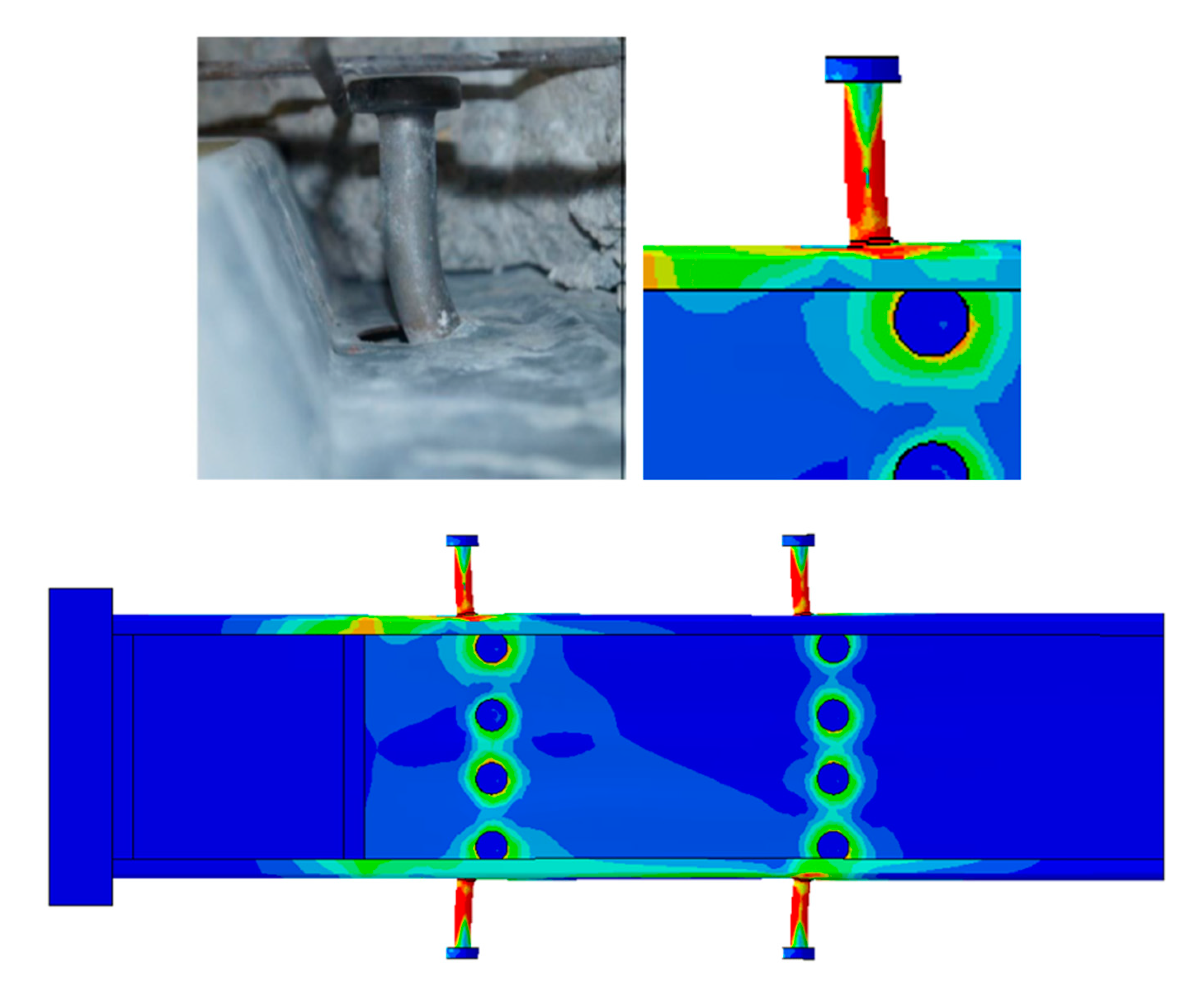
4.2. Standard Headed Stud Shear Connector (HSSC)
5. Validation of the Proposed FE Model
6. Conclusions
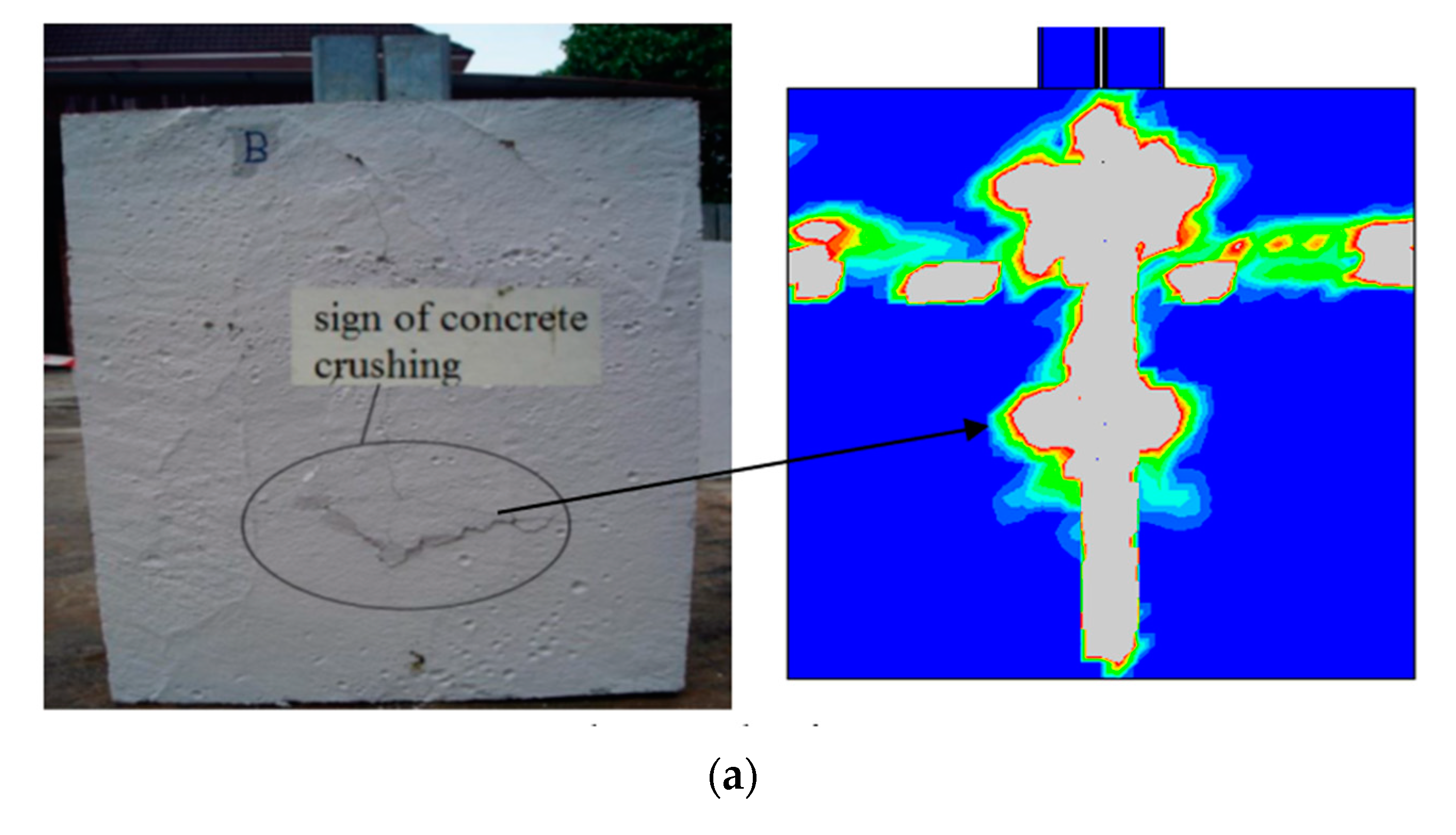
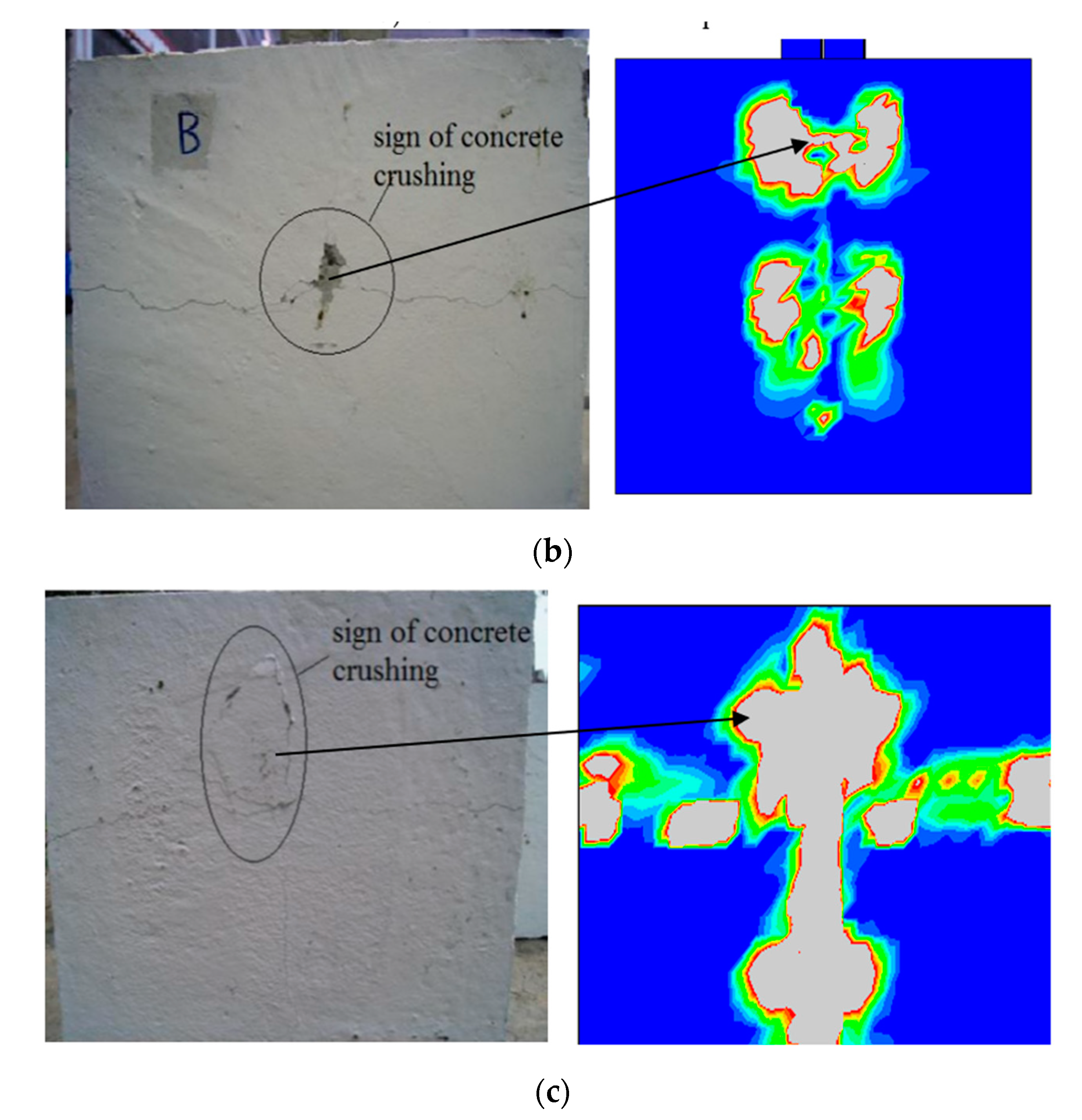
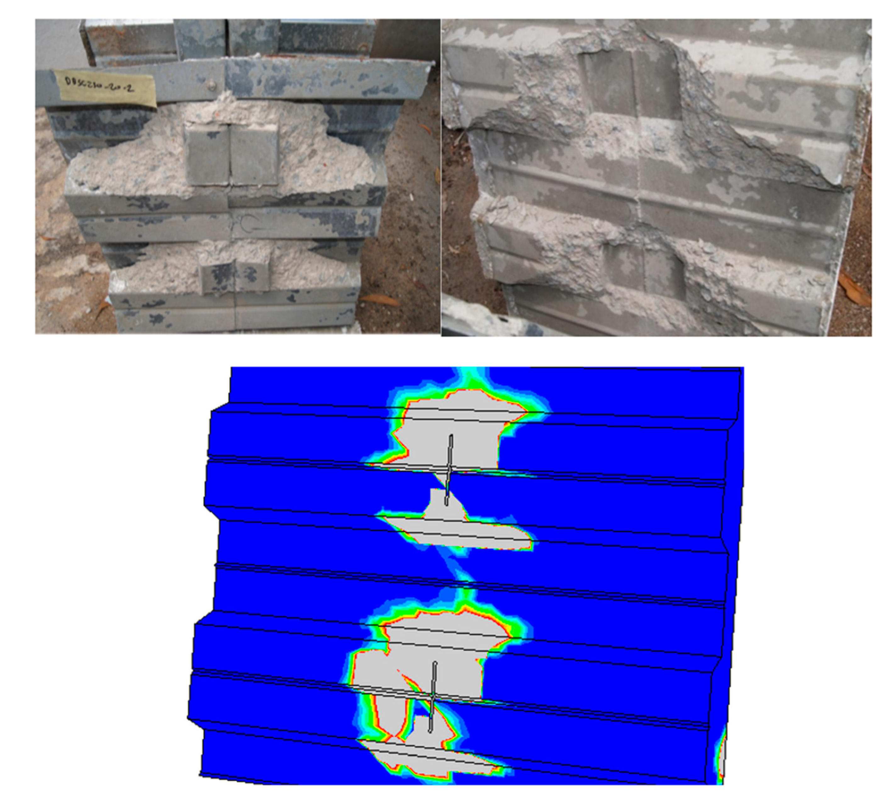
- The developed finite element models are in good agreement with the experimental results of the push tests and observations. The deformed shapes and the relevant failure modes were accurately captured by the model for all types of shear connectors. For example, the concrete crushing and shear connector rotation in SBSC, DBSC, and HPSC push test specimens were clearly captured by the FE model.
- The concrete damaged plasticity model in ABAQUS can accurately capture crushing and the longitudinal crack of a concrete slab, which is the common failure mode for SBSC, DBSC, and HPSC.
- The developed finite element models accurately model the interaction between the metal decking and concrete slab. For DSBC, the separation between the concrete slab and metal deck occurred is clearly captured by the proposed finite element models. This weak connection is due to the DBSC shear connector’s wide flange surface (double of the SBSC) that leads to such separation.
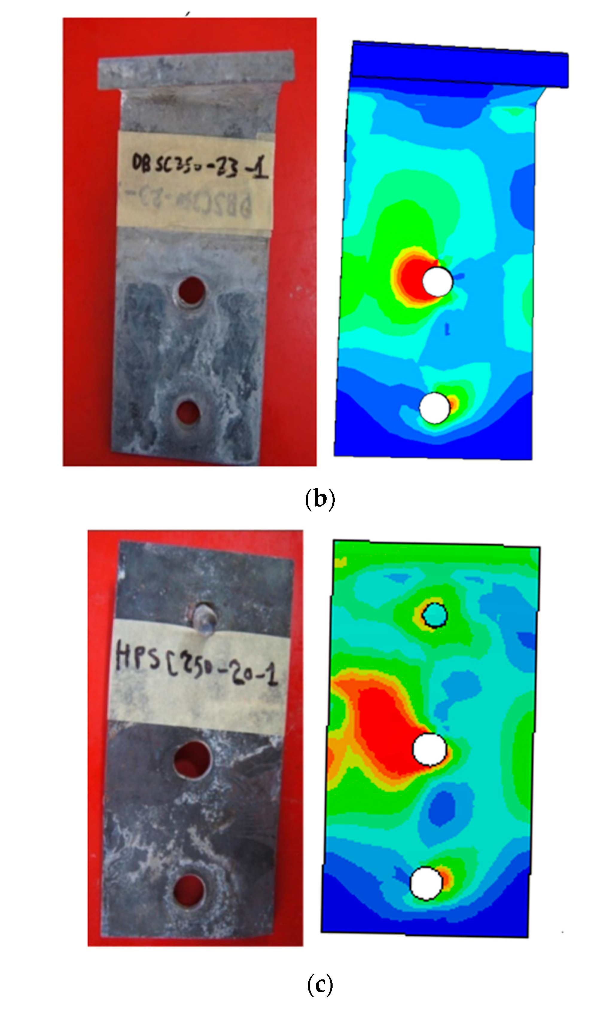
- The bearing around the bolt of shear connector that is near to the concrete slab (which was the only bolt resisting the rotation after concrete slab crushing) in the test results of SBSC, DBSC, and HPSC specimens is accurately predicted by the model by observed stress concentration around the bolt hole connecting the shear studs to the web of the cold formed beam.
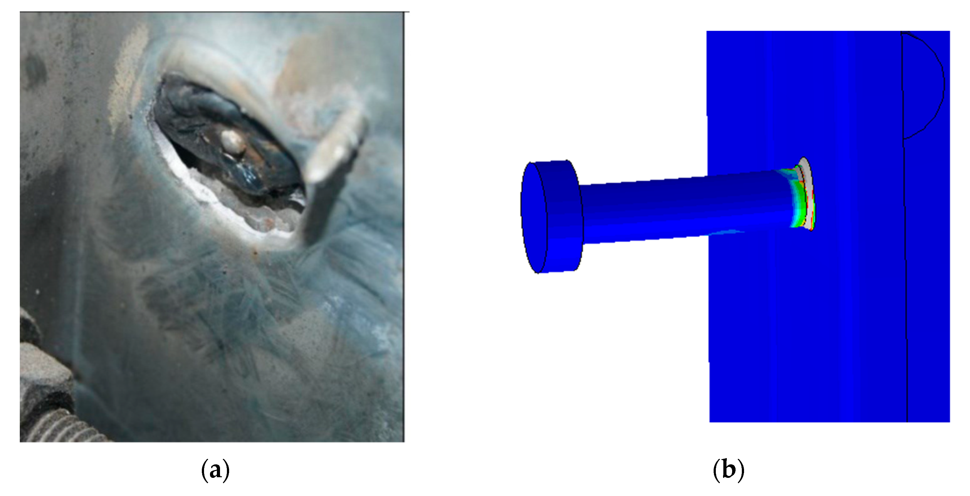
- The proposed finite element models have clearly captured the failure modes of HSSC specimens being the deformation of the shank and the pulling-out of the stud from the thinner flange of steel beam for HSSC specimens, while no crack was observed in the concrete slab.
- The finite element results of ultimate loads were found to be in very acceptable agreement with experimental data, ranging between 0.94 and 1.04. However, the results of the section analysis are generally conservative compared to experiments.
Author Contributions
Funding
Institutional Review Board Statement
Informed Consent Statement
Data Availability Statement
Conflicts of Interest
References
- Schafer, B.W. Cold-formed steel structures around the world: A review of recent advances in applications, analysis and design. Steel Constr. 2011, 4, 141–149. [Google Scholar] [CrossRef]
- Macdonald, M.; Heiyantuduwa, M.A. Rhodes J. Recent developments in the design of cold-formed steel members and structures. Thin-Walled Struct. 2008, 46, 1047–1053. [Google Scholar] [CrossRef]
- Yu, W.W. Cold-Formed Steel Design, 3rd ed.; John Wiley and Sons Inc.: Bridgewater, NJ, USA, 2000. [Google Scholar]
- Hancock, G.J.; Murray, T.; Ellifrit, D.S. Cold-Formed Steel Structures to the AISI Specification; CRC Press: Boca Raton, FL, USA, 2001. [Google Scholar] [CrossRef]
- Allen, D. Mid-rise construction detailing issues with cold-formed steel and compatible construction materials. In Proceedings of the Structures Congress and Exposition, St. Louis, MO, USA, 18–21 May 2006. [Google Scholar] [CrossRef]
- Nguyen, R.P. Thin-Walled, Cold-Formed Steel Composite Beams. J. Struct. Eng. 1991, 117, 2936–2952. [Google Scholar] [CrossRef]
- Hossain, K.M.A. Designing thin-walled composite-filled beams. Proc. Inst. Civ. Eng. Struct. Build. 2005, 158, 267–278. [Google Scholar] [CrossRef]
- Hossain, K.M.A. Experimental & theoretical behavior of thin walled composite filled beams. Electron. J. Struct. Eng. 2003, 3, 117–139. [Google Scholar]
- Abdullah, R.; Tahir, M.; Osman, M. Performance of cold-formed steel of box-section as composite beam. In Proceedings of the 6th International Conference on Steel and Space Structures, Singapore, 1–3 September 1999. [Google Scholar]
- Nakamura, S. Bending Behavior of Composite Girders with Cold Formed Steel U Section. J. Struct. Eng. 2002, 128, 1169–1176. [Google Scholar] [CrossRef]
- Wehbe, N.; Wehbe, A.; Dayton, L.; Sigl, A. Development of concrete/cold formed steel composite flexural members. In Proceedings of the Structures Congress 2011, Las Vegas, NV, USA, 14–16 April 2011; pp. 3099–3109. [Google Scholar] [CrossRef]
- Hanaor, A. Tests of composite beams with cold-formed sections. J. Constr. Steel Res. 2000, 54, 245–264. [Google Scholar] [CrossRef]
- Irwan, J.M.; Hanizah, A.H.; Azmi, I.; Bambang, P.; Koh, H.B. Shear Transfer Enhancement In Precast Cold-Formed Steel-Concrete Composite Beams: Effect of Bent-Up Tabs Types and Angles. In Proceedings of the Technology and Innovation for Sustainable Development Conference (TISD2008), Khon Kaen, Thailand, 28–29 January 2008. [Google Scholar]
- Irwan, J.M.; Hanizah, A.H.; Azmi, I.; Koh, H.B. Large-scale test of symmetric cold-formed steel (CFS)concrete composite beams with BTTST enhancement. J. Constr. Steel Res. 2011, 67, 720–726. [Google Scholar] [CrossRef]
- Irwan, J.M.; Hanizah, A.H.; Azmi, I. Test of shear transfer enhancement in symmetric cold-formed steel-concrete composite beams. J. Constr. Steel Res. 2009, 65, 2087–2098. [Google Scholar] [CrossRef]
- Lakkavalli, B.S.; Liu, Y. Experimental study of composite cold-formed steel C-section floor joists. J. Constr. Steel Res. 2006, 62, 995–1006. [Google Scholar] [CrossRef]
- Malite, M.; Nimir, W.A.; de Sales, J.J.; Gonçalves, R.M. On the structural behavior of composite beams using cold-formed shapes. In Proceedings of the International Specialty Conference on Cold-Formed Steel Structures, St. Louis, MO, USA, 19–20 October 2000. [Google Scholar]
- Bamaga, S.O.; Tahir, M.M.; Tan, T.C.; Mohammad, S.; Yahya, N.; Saleh, A.L.; Rahman, A.B.A. Feasibility of developing composite action between concrete and cold-formed steel beam. J. Cent. South Univ. 2013, 20, 3689–3696. [Google Scholar] [CrossRef]
- Hsu, C.T.T.; Munoz, P.R.; Punurai, S.; Majdi, Y.; Punurai, W. Behavior of composite beams with cold-formed steel joists and concrete slab. In Proceedings of the 21st International Specialty Conference on Cold-Formed Steel Structures, St. Louis, MO, USA, 24–25 October 2012. [Google Scholar]
- Bamaga, S.O. Structural Behavior of Composite Beams with Cold Formed Steel Sections. Ph.D. Thesis, Universiti Teknologi Malaysia, Skudai, Johor, Malaysia, July 2013. [Google Scholar]
- Bamaga, S.O.; Tahir, M.M.; Tan, C.S.; Shek, P.N.; Aghlara, R. Push-out tests on three innovative shear connectors for composite cold-formed steel concrete beams. Constr. Build. Mater. 2019, 223, 288–298. [Google Scholar] [CrossRef]
- Amsyar, F.; Tan, C.S.; Ma, C.K.; Sulaiman, A. Review on Composite Joints for Cold-Formed Steel Structures. E3S Web Conf. 2018, 65, 08006. [Google Scholar] [CrossRef] [Green Version]
- Queiroz, F.D.; Vellasco, P.C.G.S.; Nethercot, D.A. Finite element modeling of composite beams with full and partial shear connection. J. Constr. Steel Res. 2007, 63, 505–521. [Google Scholar] [CrossRef]
- Firdaus, M.; Saggaff, A.; Tahir, M.M. Finite element analysis of composite beam-to-column connection with cold-formed steel section. AIP Conf. Proc. 2017, 1903, 020024. [Google Scholar] [CrossRef] [Green Version]
- SIMULIA. ABAQUS Analysis User’s Manual. Available online: http://193.136.142.5/v6.11/pdf_books/SCRIPT_USER.pdf (accessed on 25 June 2021).
- Lubliner, J.; Oliver, J.; Oller, S.; Oñate, E. A plastic-damage model for concrete. Int. J. Solids Struct. 1989, 25, 299–326. [Google Scholar] [CrossRef]
- Lee, J.; Fenves, G.L. Plastic-Damage Model for Cyclic Loading of Concrete Structures. J. Eng. Mech. 1998, 124, 892–900. [Google Scholar] [CrossRef]
- Genikomsou, A.S.; Polak, M.A. Damaged plasticity modeling of concrete in finite element analysis of reinforced concrete slabs. In Proceedings of the 9th International Conference on Fracture Mechanics of Concrete and Concrete Structures, Berkeley, CA, USA, 28 May–1 June 2016. [Google Scholar] [CrossRef]
- Demin, W.; Fukang, H. Investigation for plastic damage constitutive models of the concrete material. Procedia Eng. 2017, 210, 71–78. [Google Scholar] [CrossRef]


| Specimen | Fy (MPa) | Fu (MPa) | Fu/Fy | E (GPa) | Elongation (%) |
|---|---|---|---|---|---|
| SC250-23 | 518.67 | 558.45 | 1.07 | 187.42 | 9.20 |
| SC250-20 | 542.65 | 575.74 | 1.06 | 191.05 | 9.10 |
| Hot rolled plate | 321.79 | 464.82 | 1.44 | 185.6 | 23.70 |
| Reinforcement mesh | 640.82 | 676.91 | 1.05 | 191.67 | - |
| SDP51-10 | 678.37 | 687.00 | 1.01 | 201.25 | - |
| Specimen | Avg. Pu,per connector (kN) | Predicted Value by Finite Element Results | |
|---|---|---|---|
| Ppre. Per connector (kN) | Averg. Exp./pre. Ratio | ||
| SBSC250-20 | 43.03 | 43.63 | 0.99 |
| DBSC250-20 | 52.15 | 55.34 | 0.94 |
| HPSC250-20 | 55.45 | 55.27 | 1.00 |
| HSSC250-20 | 54.93 | 53.80 | 1.02 |
| SBSC250-23 | 44.58 | 43.00 | 1.04 |
| DBSC250-23 | 53.60 | 55.79 | 0.96 |
| HPSC250-23 | 55.15 | 55.45 | 0.99 |
| HSSC250-23 | 53.97 | 53.80 | 0.94 |
Publisher’s Note: MDPI stays neutral with regard to jurisdictional claims in published maps and institutional affiliations. |
© 2021 by the authors. Licensee MDPI, Basel, Switzerland. This article is an open access article distributed under the terms and conditions of the Creative Commons Attribution (CC BY) license (https://creativecommons.org/licenses/by/4.0/).
Share and Cite
Elsawaf, S.A.; Bamaga, S.O. Strength Capacity and Failure Mode of Shear Connectors Suitable for Composite Cold Formed Steel Beams: Numerical Study. Materials 2021, 14, 3627. https://doi.org/10.3390/ma14133627
Elsawaf SA, Bamaga SO. Strength Capacity and Failure Mode of Shear Connectors Suitable for Composite Cold Formed Steel Beams: Numerical Study. Materials. 2021; 14(13):3627. https://doi.org/10.3390/ma14133627
Chicago/Turabian StyleElsawaf, Sherif A., and Saleh O. Bamaga. 2021. "Strength Capacity and Failure Mode of Shear Connectors Suitable for Composite Cold Formed Steel Beams: Numerical Study" Materials 14, no. 13: 3627. https://doi.org/10.3390/ma14133627