Abstract
In this work, authors have designed, constructed and tested a new kind of partially superconducting axial flux machine. This model is based on the magnetic flux concentration principle. The magnetic field creation part consists of the NbTi superconducting solenoid and two YBaCuO plates. A theoretical study is conducted of an extrapolated superconducting inductor for low-temperature superconducting and high-temperature superconducting solenoids. The optimization of the inductor is carried out in order to increase the torque and the power density as well. This improvement is done by changing the shape of the elements which form the superconducting inductor. Finally, a prototype is realized, and tested.
1. Introduction
A very high power density in electrical machines can be obtained thanks to unconventional design of electromechanical converters. It is based on very high torque-to-weight and torque-to-volume ratios. The conventional electrical machines based on copper, iron and permanent magnets cannot deliver high power density, due to their inherent limitations [1]. Unconventional electrical machines consist of superconducting materials. They have impressive characteristics as well their very high magnetic flux density [2], the losslessness of DC, increasing the torque density [3], the weakness of loss with AC [4], and the diamagnetic perfectness when the bulk materials are used.
Numerous applications can benefit from this advanced technology, e.g., naval propulsion [5], wind power generation [6,7], electric vehicles [8], and aviation systems [9,10,11]. After the discovery of low temperature superconducting (LTS) materials, many superconducting machines have appeared. However, the machines’ cooling systems were very expensive, which led to manufacture limitations. The appearance of high-temperature superconducting materials (HTS) in 1986, gave a great boost to superconducting machines. Furthermore, several topologies were developed. Significant contributions of research works related to the field of superconducting machines, can be found in recent experimental works [12]. The authors of this work are interested in studying superconducting machines with magnetic flux concentration.
Masson [13,14] has studied and realized a superconducting inductor made of two coaxial coils of NbTi, wherein the two coils are fed by opposite currents, and four magnetic screens are placed between them. This structure makes it possible to obtain a variation of the magnetic flux induction; its value decreases on the superconducting screens and increases between them.
Ailam et al. [15], have successfully completed the model by adding a conventional rotating armature. The study and optimization are essentially based on the Monte Carlo method. Other studies were conducted to adapt this prototype in the aeronautics field. Moulin et al. [16,17] provided a contribution to get a prototype with bigger size. However, as the market does not meet their needs, they used a triple structure (multistack inductor). Thus, the power has been increased to 66% compared to the single superconducting inductor. El Hassan et al. [18,19] installed a circular screen bulk between the two solenoids in a way to be in an inclined position. This prototype resembles the engine of the claw pole in its operating principle. They got an induction variation of the radial magnetic flux induction approximately sinusoidal. Masson designed in [20], a superconducting machine with axial flux, it is based on the flux magnetic concentration principle. The structure is different compared to the previous ones, i.e., the superconducting coil is located outside and its armature is inside. Masson’s research team studied this model to develop future aircraft engines.
Arish et al. [21] used the HTS-Bulk YBaCuO (YBCO) and proposed a flux-switching machine and make a comparison with the classic model. The results of this axial flux permanent magnet machine provide a visible reduction in the leakage flux. The magnetic saturation and the total harmonic distribution (THD) decrease the saturation of the machine. Douine et al. [22] used HTS bulks in electrical applications and highlighted the issue of the large sizing. This research develops three main areas, presents the YBCO bulks, a motor application which uses magnetic field trapping and shielding is developed and the HTS bulks characterized. This study should provide useful to engineers seeking to design better superconducting motors.
Namburi et al. [23] highlighted the importance of recycling the “failed” YBCO materials. The paper contains the properties of the recycled samples compared with the primary grown ones. The observed changes are related to the porosity and Y2BaCuO5 distribution. The recycled samples allow one to increase their tensile strength, hardness and flexural strength. Good correlations were identified between the recycled samples and the primary grown ones. Zhang et al. [24] presented the AC loss from the perspective of quantitative and qualitative analysis methods and the techniques used on superconductors for reduction of AC loss in the electrical machines. The paper may be used to deepen the better understanding of the AC loss and is a base guide for future research. Muralidharet al. [25] presented a production process through cold-top-seeded infiltration of bulk single grain superconductors. They investigated the properties of the bulk after the addition of CeO2 and Pt. Multiple methods were tested and analyzed in the microstructures. The identified characteristics were related to its magnetic properties and the high spatial homogeneity.
Sumption et al. [26] analyzed multiple types of electrical conductors in superconducting and normal state at cryogenic temperatures. The results were compared with superconducting YBCO and MgB2. Two analysis cases were developed, and the results determined the filament size and offer a wide pallet of options. Polichetti et al. [27] varied the temperature in order to analyze type II superconductors. The S(H) curves were considered and the results were compared with the ones identified in the specialty literature. The relation identified between the SMP phenomenon in Jc(H) and the S(H) shows the availability for both of them to be attributed to a sequential crossover, regardless of the type II superconductor, which is between a less effective pinning to a more effective pinning.
Sizochenko and Hofmann [28] investigated the relations between the basic physicochemical properties and the superconductive inorganic materials at critical temperatures from a quantitative perspective. The paper provides a way to maintain a generalizable model while making more accurate interpretations. Li et al. [29] applied active vibration control to two linear electromagnetic actuators on each bogie. The results of the experiments showed that the used control strategies are comparable with the passive bogie system and to improve the classic systems’ stability. Kutt et al. [30] worked to increase the offsetting system reactive torques and the propulsion efficiency. This concept was introduced in the design of the wind turbines. Is presented a counter-rotating field axial-flux generator and armature. The design process contains three steps: the first one is analytical calculation, the second FEM simulation and the third one is the prototype experimental measurements.
Statra et al. [31] developed a semi-analytical approach based on the volume integral method conceived to commute torque and forces in a fully high temperature superconducting ironless axial flux machine (HTS IAFM). The multi objective optimization method and the genetic algorithm were used to minimize the superconducting wire length in the structure and to maximize the magnetic torque. Padmanathan et al. [32] reviewed the evolution of wind energy conversion system (WECS)-based permanent magnet synchronous generators (PMSGs) and compared the direct driven and geared conversion systems. The paper describes the electrical machines used in WECS classification, presents multiple PMSG topologies and design aspects, emphasizes the conceptual framework and the control for WECS.
Most of the previous structures are superconducting radial flux machines. Our research works revolve around the superconducting machine with axial flux. According to Gieras [33], these kinds of machine have a wide field of application with good prospects due to their higher torque density and large power density [34]. In fact, they ensure low cogging torque with low noise and low magnetic leakage flux. Ailam et al. [35,36] proposed a prototype of axial flux machine, carrying out studies on superconducting inductors using the Monte Carlo stochastic method.
There are numerous ongoing efforts all around the world on increasing the power density of machines using cryo-electrification [37,38,39,40], especially for future aviation applications [41,42,43]. In this work, the authors thus decided to design, optimize and realize a new kind of superconducting machine, based on the principle of magnetic flux concentration. As a first approach, a 3D model is designed according to the previous prototype, a conventional armature is added and the finite element (FE) method is used. This improved model is illustrated in Figure 1.
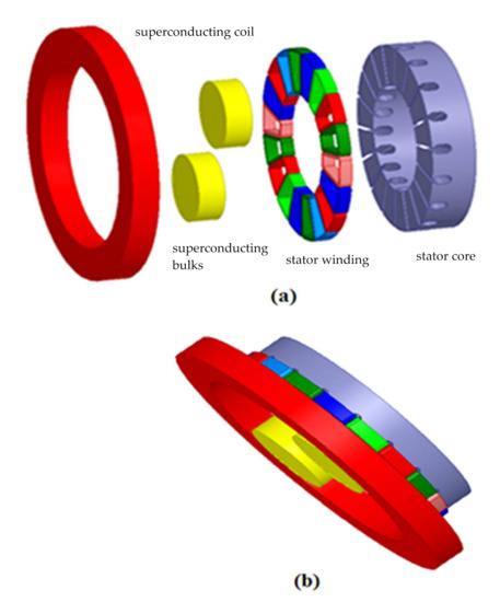
Figure 1.
Axial flux superconducting motor configuration: (a) Exploded view and (b) Assembly view.
The configuration presented in Figure 1 illustrates the different element of the considered prototype; it consists from left to right of a superconducting coil, two superconducting bulks of YBCO, eighteen coils of armature and stator’s core. Once the simulation and optimization parts are achieved, the realization phase starts, and it will be followed by the experimental validation.
2. Superconducting Inductor Design
In this section, a first technical comparison between the superconducting and the permanent magnet inductors is presented. Subsequently, the authors identified the operating point of superconductor inductor thanks to simulation results, which led to a coherent choice of inductor dimensions for the practical realization phase. The authors have then studied the superconducting coil and the superconducting inductor separately; a 3D the magnetic flux density is obtained.
2.1. Superconducting Inductor vs. Conventional Inductor
Compared to conventional machines, the proposed prototype inductor shown in Figure 2, depicts a radical change either regarding the design or the materials it consists of.
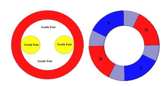
Figure 2.
Superconducting inductor’s behaviour.
Usually traditional machines’ inductors consist of iron, copper and magnets, for instance; the permanent magnets are set on an iron ring in the machine’s inductor. The studied inductor consists of a thick NbTi solenoid to get a strong magnetic field, which will be subsequently concentrated using two massive single crystal YBCOs. The characteristics are listed in Table 1 and Table 2.

Table 1.
Superconducting inductor characteristics.
Table 2.
Superconducting materials characteristics.
Compared to a permanent magnet inductor, the YBCO plates act as north poles and the space between magnetic screens behave as south poles in the superconducting inductor.
2.2. Operating Point of the Superconducting Inductor
To define the critical current that flows across the solenoid of the inductor, and given that the considered superconducting inductor contains a superconducting coil made of NbTi; the equation of the Ic (B) is used as follows:
J = −222.222B + 2000
As an assumption, a value of 100 A/mm2 for the current density is considered in this simulation. This assumption leads to a DC value of 15.19 A through the solenoid.
The maximum magnetic flux induction is obtained thanks to the load line equation (maximum magnetic field on the inductor), illustrated in Equation (2):
J = 108.7B
The intersection between the two straight lines: the load curve and the Ic (B) curve of the low temperature material (NbTi), gives the operating point of the superconducting inductor as illustrated in Figure 3.
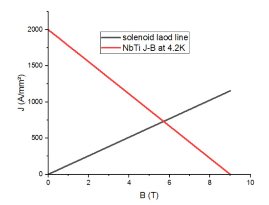
Figure 3.
Operating point of the superconducting inductor.
It can be seen from Figure 3 that solenoid load line increases starting from a nil value to reach a value of 1300 A/mm2 for the current density which corresponds to the value of 12 for the magnetic flux. At a temperature of 4.2 K, the NBTi materials evolve decreasingly, starting from a value of 2000 A/mm2 for the current density to reach zero at a corresponding value of 9 Tesla for the magnetic flux. Thus, the critical current density reached 670 A/mm2 and the electrical current I = 101 A.
2.3. The Superconducting Inductor Design
The authors suggested 15 mm in the superconducting coil thickness, due to the availability of the corresponding YBCO plates in our laboratory. The internal radius of the superconducting coil must be enough to contain the superconducting bulks and the machine shaft, with respect to the components’ spacing. The outer radius is chosen in such a way as to obtain an induction difference of magnetic flux equal to that in the air gap of conventional machines, which is equal to 2.5 Tesla. Thus, the outer radius is 85 mm.
Superconducting Inductor vs. Superconducting Coil
After inserting both YBCO plates in the previous structure, a magnetic flux concentration is obtained. In consequence, the magnetic field increases between the magnetic screens. The magnetic induction decreases with both superconducting bulks; a smaller value of magnetic flux induction is obtained while approaching the bulk’s center as shown in Figure 4.
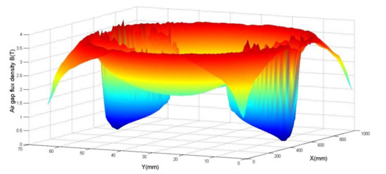
Figure 4.
Magnetic flux density map to the inductor in 3D at a distance of 0.5 mm.
Nonetheless, the magnetic field increases at the edges of YBCO plates. We also notice that because of its lines’ focus.
The comparison of the inductor with the coil alone (Figure 5 illustrates the distribution of magnetic flux induction in a thick coil) reveals a higher magnetic flux induction between the superconducting bulks of the inductor.
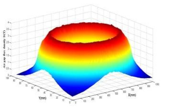
Figure 5.
3D magnetic flux density map at 0.5 mm of superconducting solenoid.
According to Figure 6, the magnetic flux induction is calculated firstly in the YBaCuO plate for different values in the (X-axis) at z = 0.5 mm away from the inductor (Z-axis). In the second case, the magnetic flux induction is calculated at (x = 0 mm) for different values in the (Y-axis) for z = 0.5 mm.
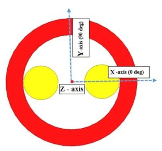
Figure 6.
Axes to calculate magnetic flux induction.
After the dimensions of the superconducting inductor have been fixed (Rext = 85 mm, Rint = 63 mm, L = 15 mm), the magnetic induction on the axis which is the pellet (Bx) and the magnetic induction on the axis which is between the two pellets (Bd) and the difference (∆B) between the two magnetic inductions (Bd-Bx) obtained, which is an important factor to obtain the electromagnetic torque in electric machines, were calculated. The magnetic flux induction calculated on Y-axis, Bd and Bx and ΔB are calculated, and are presented in Figure 7.
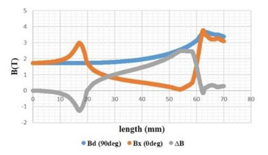
Figure 7.
Variation of the maximum magnetic flux induction at 0.5 mm from the inductor along the radius.
The evolution of electromagnetic flux induction differs for each axis. A continued increase is observed in Bd (90°) to almost 4 Tesla, unlike that observed for Bx which seems to vary periodically across the radius length, it is also considered as an unstable evolution. However, ΔB reveals a difference of up to 2 Tesla in the region starting from 20 mm to 50 mm. This difference decreases to be almost after 60 mm. Hence, the electromagnetic flux induction is much stable in both directions within a radius of no less than 60 mm.
2.4. Prototype Optimization
The idea adopted to optimize the performance of our machine is to vary the superconducting inductor shape to get a high magnetic flux induction, and consequently the electromagnetic torque, as well as the electromagnetic power.
2.4.1. Shape Optimization
To optimize the performance of our inductor, two methods can be adopted: (i) varying the superconducting coil shape while keeping the same distance between the two superconducting bulks and their length. The difference between the external and internal perimeters (22 mm) of the inductor coil as shown in Figure 8a. (ii) keeping the circular form of the inductor coil and varying the form of the YBCO bulk as shown in Figure 8b.
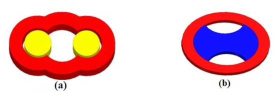
Figure 8.
New kind of superconducting inductors: (a) inductor with optimized coil, (b) inductor with optimized YBCO plat.
According to Figure 9, the inductor with optimized YBCO bulk presents remarkable results. In fact, it leads to get highest value of the normal magnetic flux induction as compared to the two other forms. Since this form is practically unrealizable, our study will be limited to the first form studied.
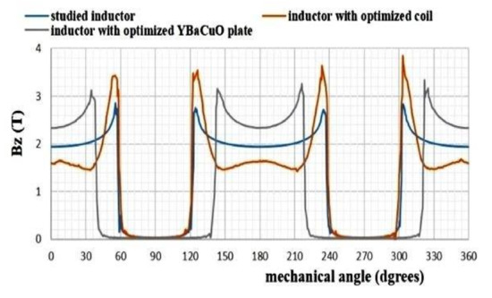
Figure 9.
Comparison of the magnetic flux inductions created by the three superconducting inductors.
Obviously, studied inductor presents a mean value of 2 Tesla instead of 1.8 and 2.3 Tesla for inductor with optimized coil and for inductor with optimized YBaCuO plate, respectively.
2.4.2. Superconducting Wire Optimization
Superconducting wires are evaluated theoretically under two different low and high temperature scenarios, i.e., LTS material at 4.2 K and HTS material at 4.2 K and at 22 K, shown in Figure 10.
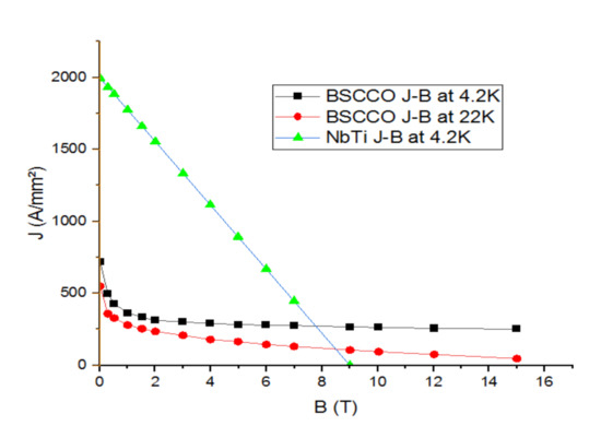
Figure 10.
Critical currents of different superconducting wires vs. applied magnetics field.
It is obvious to observe that temperature affects the BSCCO J-B curves. In fact, lower electromagnetic inductor performances can be obtained by increasing the temperature.
Figure 11 presents the development of the maximum magnetic flux density according to outer radius which varies from 70 to 200 mm above the inductor with different wires; length and inner radius are kept to the values 15 and 63 mm, respectively. Each time the outer radius is changed the abovementioned process must be repeated. In fact, this step is useful to determine the operating point, and consequently the maximal value of the flux density on the wire.
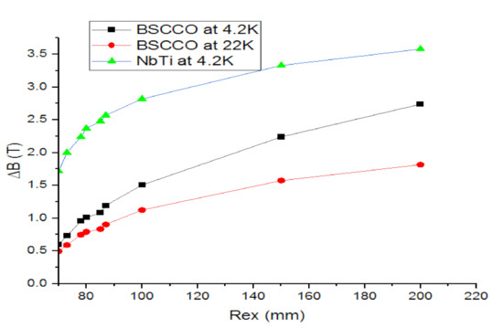
Figure 11.
Variation maximum magnetic flux density (ΔB) vs. Rext on inductor with different wires.
According to Figure 11, the inductor with LTS material at 4.2 K has a considerable maximum magnetic flux density as compared to the one with HTS material at 4.2 K and 22 K.
A proportional relation is observed with ΔB and external radius. It can be observed that the difference is more important at 4.2 K for the BSCCO. Although, the ΔB of the NbTi is greater than BSCCO at 4.2 K.
2.5. Superconducting Machine
The authors’ prototype contains a superconducting inductor and a three-phase conventional axial armature, as shown in Figure 1. The stator of this prototype is not concerned in this study, therefore the dimensions are chosen on the basis of Equation (3) [44,45]:
where internal diameter (Dint) and exterior diameter (Dext).
Table 3 presents the different characteristics of our machine.
Table 3.
Characteristics of the machine’s stator.
Figure 12 represents the magnetic flux induction normal for a 4-pole axial flux superconducting machine, whose air gap e = 0.5 mm, knowing that the inductor excitation current I = 101 A, the current density j = 670 A/mm2, and the rotation speed N = 1400 rpm.
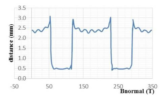
Figure 12.
Magnetic flux induction normal in air gap created by the superconducting machine.
The magnetic flux induction normal reaches its maximum value between the two superconducting bulks and reaches the minimum above them.
2.6. Induced Voltage
In Figure 13, the induced voltage is almost sinusoidal; it reaches the peak value of (200 V) when the stator machine is used, and it decreases when the coreless winding stator is used.
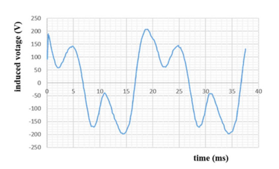
Figure 13.
One phase of electromotive force created by the superconducting machine.
From Figure 13, It can be observed that the induced voltage swings between two maximum positive value of 200 V in a period of 20 ms. During the first 5 ms, the voltage drops to the value of 150 before reaching a negative value that mirrors the positive one.
3. Realization and Test
A schematic diagram of the experimental configuration regarding the way in which the system’s connection was performed in order to perform the tests is displayed in Figure 14. For measure B, a gaussmeter (DX-102, Dexing Magnet, Jiangshu, China) was used, that is based on a Hall effect sensor, with precision and accuracy bands: a—better than 1.0% (0 ± 1000 mT), b—better than 2.0% (1000 ± 2000 mT) and c—better than 4.0% (2000 ± 3000 mT).
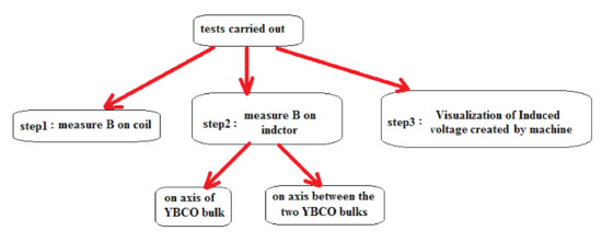
Figure 14.
Schematic diagram of the experimental configuration.
As a modeling method, a software program was used that is based on the finite element method, being solved simultaneously the four Maxwell equations:
Combining Equations (4)–(7) and solving them for magnetic vector potential and electric scalar potential will result in the following equation [46]:
The validation of the results can be summarized as follows: first, the work was started by calculated and validated B in axes of a thick coil by using both analytical and modeling methods, and then the activity was continued. In the tests phase the results were experimentally validated by FEM as shown in figures below.
3.1. Inductor Realized and Test
We will introduce the prototype made (Figure 15), as well as the performed tests at the “LESI” research laboratory. To minimize the realization costs, an inductor coil of copper is realized.
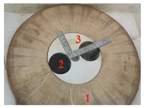
Figure 15.
Superconducting inductor: (1) copper coil, (2) YBCO plate, (3) forex material machine.
The table below shows the different characteristics of this coil (refer to Table 4).
Table 4.
Characteristics of the solenoid stator.
The three lines in Figure 16 indicate the magnetic flux induction variation versus the coil radius. The magnetic flux induction increases while approaching the coil’s internal radius.
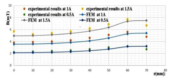
Figure 16.
Comparative graph of the FEM vs. the experimental magnetic flux induction on copper coil.
The three lines in Figure 17 indicate the magnetic flux induction variation versus the inductor radius between the superconducting bulks. As expected, the magnetic flux induction increases while approaching the inductor’s internal radius.
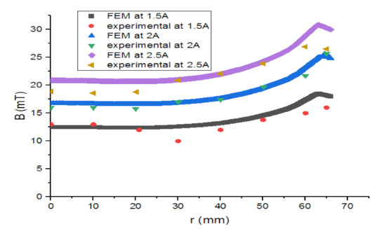
Figure 17.
Comparative graph of the FEM vs. the experimental magnetic flux induction between the superconducting bulks.
In Figure 18 the magnetic flux induction becomes almost null on the superconducting bulk centre. The curves of Figure 16, Figure 17 and Figure 18 show that there is a concordance between the simulation results and those of the empirical part.
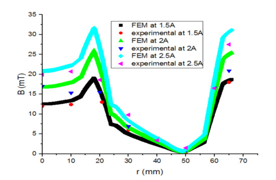
Figure 18.
Comparative graph of the FEM vs. the experimental magnetic flux induction behind superconducting bulks.
Figure 19 presents the difference between the two previous magnetic flux induction graphs. It is remarkable that ΔB increases when the inductor’s current intensity is high, and vice versa. The electromagnetic torque is proportional to ΔB, as well as to the power density.
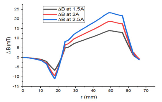
Figure 19.
ΔB of superconducting inductor versus different currents.
3.2. Realization of the Armature Winding
Figure 20 and Table 5 present the design, dimensions, and realization of the stator of our prototype. It is a pulley which consists of six coils made of copper, All of them contain a laminated trapezoidal iron core in order to reduce the eddy current loss.
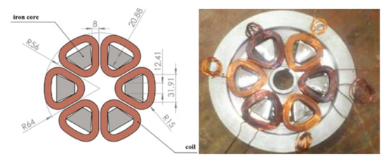
Figure 20.
Design and realization of the stator of the machine.
Table 5.
Characteristic of the realized stator.
3.3. Induced Electromotive Force Created by Prototype
To finalize the testing step, we take the model as a whole (the armature and the inductor) and test it as a generator. To optimize the operation conditions of the superconducting bulks, a cooling process is required under the effect of magnetic field (Figure 21). The inductor (coil and two YBCO bulks) is immersed in a bath of liquid nitrogen (77 k) after that it is supplied with a direct current, this method is known as zero field cooling. Therefore, the inductor coil is fed with an excitation current Iexc = 2.85 A. Afterward, liquid nitrogen is dumped on the inductor. The armature is driven by a second motor (single-phase synchronous motor), so that the rotational speed becomes 890 rpm. Finally, the output voltages are visualized using the Digital Signal Processing and Control Engineering (DSPACE) software (dSPACE Ltd., Melbourn, UK).
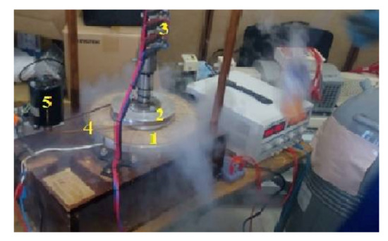
Figure 21.
Prototype under tests: (1) inductor, (2) stator, (3) brushes and rings, (4) transmission belt, (5) synchronous motor.
The machine is tested as a generator with an opened or short-circuited armature (no-load test) with the principle scheme presented in Figure 22. The armature ends are connected to a DSPACE to observe the line to line voltages [15].
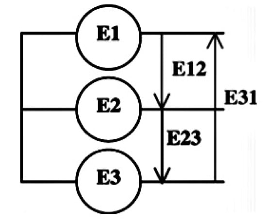
Figure 22.
Measured voltages.
Results are shown in Figure 23 below. The high attractive force between the rotor and the stator creates the distortion problem. The results are satisfactory and almost sinusoidal.
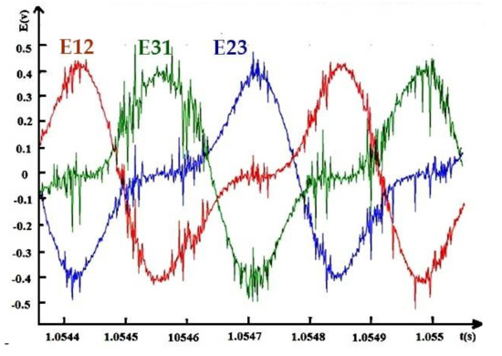
Figure 23.
Induced voltage created by the realized machine; Iexc = 2.85 A, N = 890 rpm.
The data in Figure 23 were recorded thanks to the DSPACE platform, which is why high fluctuations appeared.
4. Conclusions
Superconducting motors represent a promising way to make superconductivity commercially operational in real electric power systems. The fast development in the superconducting materials industry is related to the improvement of the performance of these electric motors.
A new kind of partially superconducting machine model with axial flux is designed and studied in this work. It is based on the principle of magnetic flux concentration. This unconventional inductor, which consists of two YBaCuO (YBCO) plates and the NbTi superconducting solenoid is immersed in liquid nitrogen. The superconducting coil is used for creation of the magnetic flux and it is concentrated by the YBaCuO plates. Optimization of the inductor is carried out in order to increase the torque and the power density as well.
To make the cooling process easier and more economical, this unconventional machine has a stationary superconducting inductor positioned horizontally.
The main results shown that magnetic flux is considerable between the inductor’s YBaCuO plates and it almost null behind them. Experimentally, the obtained induced voltage is almost sinusoidal, which is common to conventional machines. In perspective, a fully superconducting machine is the subject of optimization and a cooling procedure (this part is targeted as a research direction that will be addressed by the authors in the near future).
Author Contributions
Conceptualization, B.C.D. and E.A.; methodology, B.C.D. and E.A.; software, B.C.D., B.A., C.F., M.S.R. and E.A.; validation, B.C.D., B.A., E.A., C.F., M.S.R., C.D. and R.-A.F.; formal analysis, B.C.D., B.A., C.F., M.S.R. and E.A.; investigation, B.C.D., B.A., M.S.R., C.F., E.A., C.D. and R.-A.F.; resources, B.C.D., B.A. and E.A.; data curation, B.C.D., B.A., C.F., M.S.R., E.A., C.D. and R.-A.F.; writing—original draft preparation, B.C.D., B.A., M.S.R. and R.-A.F.; writing—review and editing, B.A., C.F., M.S.R., E.A., C.D. and R.-A.F.; visualization, B.C.D., B.A., C.F., M.S.R., E.A., C.D. and R.-A.F.; supervision, B.C.D., B.A., M.S.R., E.A. and R.-A.F.; project administration, B.C.D., B.A. and E.A.; funding acquisition, R.-A.F., C.F. and M.S.R. All authors have read and agreed to the published version of the manuscript.
Funding
This research received no external funding.
Institutional Review Board Statement
Not applicable.
Informed Consent Statement
Not applicable.
Data Availability Statement
Not applicable.
Acknowledgments
Authors acknowledge the LESI Laboratory for their technical support. This work was supported by a grant of the Romanian Ministry of Research and Innovation, CCCDI-UEFISCDI, project number PN-III-P1-1.2-PCCDI-2017-0776/No. 36 PCCDI/15.03.2018, within PNCDI III. Acknowledgments to the National Center for Hydrogen and Fuel Cells (CNHPC)—Installations and Special Objectives of National Interest (IOSIN).
Conflicts of Interest
The authors declare no conflict of interest.
References
- Luk, P.C. Superconducting machines—The enabling technology for future electric propulsion in aircraft. In Proceedings of the 2017 7th International Conference on Power Electronics Systems and Applications-Smart Mobility, Power Transfer & Security (PESA), Hong Kong, China, 12–14 December 2017; pp. 1–7. [Google Scholar] [CrossRef]
- Hirakawa, M.; Inadama, S.; Kikukawa, K.; Suzuki, E.; Nakasima, H. Developments of superconducting motor with YBCO bulk magnets. Phys. C Supercond. 2003, 392–396, 773–776. [Google Scholar] [CrossRef]
- Zhu, G.; Li, L.; Liu, X.; Chen, H.; Jiang, W.; Xue, M.; Li, M. Design Optimization of a HTS-Modulated PM Wind Generator. IEEE Trans. Appl. Supercond. 2021. [CrossRef]
- Bray, J.W. High-temperature superconducting motors and generators for power grid applications. In Superconductors in the Power Grid; Woodhead Publishing: Shaxton, UK, 2015; pp. 325–344. [Google Scholar] [CrossRef]
- Gubser, D.U. Superconducting motors and generators for naval applications. Phys. C Supercond. 2003, 392–396, 1192–1195. [Google Scholar] [CrossRef]
- Badea, G.; Felseghi, R.-A.; Aschilean, I.; Bolboaca, A.M.; Muresan, D.; Soimosan, T.; Stefanescu, I.; Raboaca, S. Energen system for power supply of passive house: Case study. In Proceedings of the Second International Conference on Mathematics and Computers in Sciences and in Industry (MCSI), Sliema, Malta, 17 August 2015; pp. 24–31. [Google Scholar] [CrossRef]
- Balachandran, T.; Yoon, A.; Lee, D.; Xiao, J.; Haran, K.S. Ultra-High-Field, High-Efficiency Superconducting Machines for Offshore Wind Turbines. IEEE Trans. Magn. 2021. [CrossRef]
- Rata, M.; Rata, G.; Filote, C.; Raboaca, M.S.; Graur, A.; Afanasov, C.; Felseghi, A.-R. The ElectricalVehicle Simulator for Charging Station in Mode 3 of IEC 61851-1 Standard. Energies 2020, 13, 176. [Google Scholar] [CrossRef]
- Kelouaz, M.; Ouazir, Y.; Hadjout, L.; Mezani, S.; Lubin, T.; Berger, K.; Lévêque, J. 3D Magnetic field modeling of a new superconducting synchronous machine using reluctance network method. Phys. C Supercond. 2018, 548, 5–13. [Google Scholar] [CrossRef]
- Kovalev, K.; Nekrasova, J.; Ivanov, N.; Zhurzvlev, S. Design of all-superconducting electrical motor for full electric aircraft. In Proceedings of the 2019 International Conference on Electrotechnical Complexes and Systems (ICOECS), Ufa, Russia, 21–25 October 2019; pp. 1–5. [Google Scholar] [CrossRef]
- Yazdani-Asrami, M.; Song, W.; Zhang, M.; Yuan, W.; Pei, X. Magnetization Loss in HTS Coated Conductor Exposed to Harmonic External Magnetic Fields for Superconducting Rotating Machine Applications. IEEE Access 2021, 9, 77930–77937. [Google Scholar] [CrossRef]
- Haran, K.S.; Kalsi, S.; Arndt, T.; Karmaker, H.; Badcock, R.; Buckley, B.; Stautner, E.W. High power density superconducting rotating machines—Development status and technology roadmap. Supercond. Sci. Technol. 2017, 30, 123002. [Google Scholar] [CrossRef]
- Masson, P.; Netter, D.; Levêque, J.; Rezzoug, A. Magnetic field concentration: Comparison between several shapes of superconducting shields. IEEE Trans. Appl. Supercond. 2001, 11, 2248–2251. [Google Scholar] [CrossRef]
- Masson, P.; Levêque, J.; Netter, D.; Rezzoug, A. Experimental study of a new kind of superconducting inductor. IEEE Trans. Appl. Supercond. 2003, 13, 2239–2242. [Google Scholar] [CrossRef]
- Ailam, E.H.; Netter, D.; Leveque, J.; Douine, B.; Masson, P.J.; Rezzoug, A. Design and Testing of a Superconducting Rotating Machine. IEEE Trans. Appl. Supercond. 2007, 17, 27–33. [Google Scholar] [CrossRef]
- Moulin, R.; Levêque, J.; Mercier, J.; Rezzoug, A.; Netter, D. Superconducting multi-stacks motors using the diamagnetism property of bulk material. In Proceedings of the 2008 18th International Conference on Electrical Machines, Vilamoura, Portugal, 6–9 September 2008; pp. 1–4. [Google Scholar] [CrossRef]
- Moulin, R.; Leveque, J.; Durantay, L.; Douine, B.; Netter, D.; Rezzoug, A. Superconducting Multistack Inductor for Synchronous Motors Using the Diamagnetism Property of Bulk Material. IEEE Trans. Ind. Electron. 2009, 57, 146–153. [Google Scholar] [CrossRef]
- Alhasan, R.; Lubin, T.; Lévêque, J. Study and test of a new superconducting inductor structure for a synchronous machine. In Proceedings of the 2014 International Conference on Electrical Sciences and Technologies in Maghreb (CISTEM), Tunis, Tunisia, 3–6 November 2014; pp. 1–7. [Google Scholar] [CrossRef]
- Alhasan, R.; Lubin, T.; Douine, B.; Adilov, Z.M.; Leveque, J. Test of an Original Superconducting Synchronous Machine Based on Magnetic Shielding. IEEE Trans. Appl. Supercond. 2016, 26, 1–5. [Google Scholar] [CrossRef]
- Masson, P.J.; Breschi, M.; Tixador, P.; Luongo, C.A. Design of HTS Axial Flux Motor for Aircraft Propulsion. IEEE Trans. Appl. Supercond. 2007, 17, 1533–1536. [Google Scholar] [CrossRef]
- Arish, N.; Marignetti, F.; Yazdani-Asrami, M. Comparative study of a new structure of HTS-bulk axial flux-switching machine. Phys. C Supercond. 2021, 584, 1353854. [Google Scholar] [CrossRef]
- Douine, B.; Berger, K.; Ivanov, N. Characterization of High-Temperature Superconductor Bulks for Electrical Machine Application. Materials 2021, 14, 1636. [Google Scholar] [CrossRef] [PubMed]
- Namburi, D.K.; Singh, K.; Huang, K.Y.; Neelakantan, S.; Durrell, J.H.; Cardwell, D.A. Improved mechanical properties through recycling of Y-Ba-Cu-O bulk superconductors. J. Eur. Ceram. Soc. 2021, 41, 3480–3492. [Google Scholar] [CrossRef]
- Zhang, H.; Wen, Z.; Grilli, F.; Gyftakis, K.; Mueller, M. Alternating Current Loss of Superconductors Applied to Superconducting Electrical Machines. Energies 2021, 14, 2234. [Google Scholar] [CrossRef]
- Muralidhar, M.; Jirsa, M.; Murakami, M. Enhanced flux pinning of single grain bulk (Gd, Dy)BCO superconductors processed by cold-top-seeded infiltration growth method. Mater. Sci. Eng. B 2020, 253, 114494. [Google Scholar] [CrossRef]
- Sumption, M.; Murphy, J.; Susner, M.; Haugan, T. Performance metrics of electrical conductors for aerospace cryogenic motors, generators, and transmission cables. Cryog. 2020, 111, 103171. [Google Scholar] [CrossRef]
- Polichetti, M.; Galluzzi, A.; Buchkov, K.; Tomov, V.; Nazarova, E.; Leo, A.; Grimaldi, G.; Pace, S. A precursor mechanism triggering the second magnetization peak phenomenon in superconducting materials. Sci. Rep. 2021, 11, 1–9. [Google Scholar] [CrossRef]
- Sizochenko, N.; Hofmann, M. Predictive Modeling of Critical Temperatures in Superconducting Materials. Molecules 2021, 26, 8. [Google Scholar] [CrossRef]
- Li, Q.; Deng, Z.; Wang, L.; Li, H.; Zhang, J.; Rodriguez, E.F. Active vibration control of secondary suspension based on high-temperature superconducting maglev vehicle system. Phys. C Supercond. 2021, 585, 1353872. [Google Scholar] [CrossRef]
- Kutt, F.; Blecharz, K.; Karkosiński, D. Axial-Flux Permanent-Magnet Dual-Rotor Generator for a Counter-Rotating Wind Turbine. Energies 2020, 13, 2833. [Google Scholar] [CrossRef]
- Calamiotou, M.; Lampakis, D.; Zhigadlo, N.; Katrych, S.; Karpinskic, J.; Fitch, A.; Tsiaklagkanos, P.; Liarokapis, E. Local lattice distortions vs. structural phase transition in NdFeAsO 1 − x F x. Phys. C Supercond. 2016, 527, 55–62. [Google Scholar] [CrossRef][Green Version]
- Padmanathan, K.; Kamalakannan, N.; Sanjeevikumar, P.; Blaabjerg, F.; Holm-Nielsen, J.B.; Uma, G.; Arul, R.; Rajesh, R.; Srinivasan, A.; Baskaran, J. Conceptual Framework of Antecedents to Trends on Permanent Magnet Synchronous Generators for Wind Energy Conversion Systems. Energies 2019, 12, 2616. [Google Scholar] [CrossRef]
- Gieras, J.F. Advancements in Electric Machines; Springer Science & Business Media: Berlin, Germany, 2008; Available online: https://www.springer.com/gp/book/9781402090066 (accessed on 10 March 2021).
- Wang, X.; Zhao, M.; Zhou, Y.; Xu, W.; Wan, Z. Design and Analysis for Multi-Disc Coreless Axial-Flux Permanent-Magnet Synchronous Machine. IEEE Trans. Appl. Supercond. 2021. [CrossRef]
- Ailam, E.H.; Hachama, M.; Benallal, M.N.; Mehabil, Y.; Leveque, J.; Rezzoug, A. Study of an Axial Superconducting Motor Using the Monte Carlo Method. IEEE Trans. Appl. Supercond. 2013, 23, 5201404. [Google Scholar] [CrossRef]
- Elbaa, M.; Bentridi, S.E.; Douine, B.; Berger, K.; Lévêque, J. Résolution de l’équation de Laplace par la méthode de Monte Carlo: Application à une bobine supraconductrice. In Proceedings of the CISTEM 2016-Conférence Internationale en Sciences et Technologies Electriques au Maghreb, Marrakech, Maroc, 26–28 October 2016; pp. 1–4. Available online: https://hal.archives-ouvertes.fr/hal-01501819/ (accessed on 12 March 2021).
- Messina, G.; Yazdani-Asrami, M.; Marignetti, F.; della Corte, A. Characterization of HTS Coils for Superconducting Rotating Electric Machine Applications: Challenges, Material Selection, Winding Process, and Testing. IEEE Trans. Appl. Supercond. 2021, 31, 1–10. [Google Scholar] [CrossRef]
- Biasion, M.; Fernandes, J.F.P.; Vaschetto, S.; Cavagnino, A.; Tenconi, A. Superconductivity and its Application in the Field of Electrical Machines. In Proceedings of the 2021 IEEE International Electric Machines & Drives Conference (IEMDC), Hartford, CT, USA, 17–20 May 2021; pp. 1–7. [Google Scholar] [CrossRef]
- MacManus-Driscoll, J.L.; Wimbush, S.C. Processing and application of high-temperature superconducting coated conductors. Nat. Rev. Mater. 2021, 6, 1–18. [Google Scholar] [CrossRef]
- Zhang, Y.; Cheng, Y.; Fan, X.; Li, D.; Qu, R. Electromagnetic Fault Analysis of Superconducting Wind Generator with Different Topologies. IEEE Trans. Appl. Supercond. 2021, 31, 1–6. [Google Scholar] [CrossRef]
- Yazdani-Asrami, M.; Zhang, M.; Yuan, W. Challenges for developing high temperature superconducting ring magnets for rotating electric machine applications in future electric aircrafts. J. Magn. Magn. Mater. 2021, 522, 167543. [Google Scholar] [CrossRef]
- Wheeler, P.; Sirimanna, T.S.; Bozhko, S.; Haran, K.S. Electric/Hybrid-Electric Aircraft Propulsion Systems. Proc. IEEE 2021, 109, 1115–1127. [Google Scholar] [CrossRef]
- Dorget, R.; Nouailhetas, Q.; Colle, A.; Berger, K.; Sudo, K.; Ayat, S.; Lévêque, J.; Koblischka, M.; Sakai, N.; Oka, T.; et al. Review on the Use of Superconducting Bulks for Magnetic Screening in Electrical Machines for Aircraft Applications. Materials 2021, 14, 2847. [Google Scholar] [CrossRef] [PubMed]
- Gieras, J.F.; Wang, R.J.; Kamper, M.J. Axial Flux Permanent Magnet Brushless Machines; Springer Science & Business Media: Berlin, Germany, 2008; Available online: https://link.springer.com/book/10.1007/978-1-4020-8227-6 (accessed on 18 March 2021).
- Messina, G.; De Bella, E.T.; Morici, L. HTS Axial Flux Permanent Magnets Electrical Machine Prototype: Design and Test Results. IEEE Trans. Appl. Supercond. 2019, 29, 1–5. [Google Scholar] [CrossRef]
- Mardiha, M.; Vakilian, M. Design and electromagnetic analysis of a superconducting rotating machine. In Proceedings of the 2008 Australasian Universities Power Engineering Conference, Sydney, NSW, Australia, 14–17 December 2008; pp. 1–3. Available online: https://ieeexplore.ieee.org/abstract/document/4813097 (accessed on 18 March 2021).


Publisher’s Note: MDPI stays neutral with regard to jurisdictional claims in published maps and institutional affiliations. |
© 2021 by the authors. Licensee MDPI, Basel, Switzerland. This article is an open access article distributed under the terms and conditions of the Creative Commons Attribution (CC BY) license (https://creativecommons.org/licenses/by/4.0/).