Abstract
This paper aims to analytically derive bending equations, as well as semi-analytically predict the deflection of prismatic SMA beams in the martensite phase. To this end, we are required to employ a simplified one-dimensional parametric model considering asymmetric response in tension and compression for martensitic beams. The model takes into account the different material parameters in martensite twined and detwinned phases as well as elastic modulus depending on the progress of the detwinning process. In addition, the model considers the diverse slope of loading and unloading in martensite detwinned phases favored by tension and compression. To acquire general bending equations, we first solve the pure bending problem of a prismatic SMA beam. Three different phases are assumed in the unloading procedure and the effect of neutral fiber distance from the centerline is also considered during this stage. Then according to the pure bending solution and employing semi-analytical methods, general bending equations of an SMA beam are derived. Polynomial approximation functions are utilized to obtain the beam deflection–length relationship. To validate the attained analytical expressions, several three- and four-point bending tests were conducted for rectangular and circular SMA beams. Experimental data confirm the reasonable accuracy of the analytical results. This work may be envisaged to go deep enough in investigating the response of SMA beams under an arbitrary transverse loading and stress distribution during loading and unloading, as well as findings may be applicable to a good prediction of bending behavior.
1. Introduction
One of the smart class of materials distinguished by its two well-known behavior and a highly nonlinear stress–strain curve is shape memory alloy (SMA). Exhibiting pseudo-elasticity (PE) and shape memory effect (SME), as well as thermo-mechanically coupled responses have extensively opened up ample opportunities to utilize SMAs in different industrial sectors. SMAs can be used in numerous fields, including aerospace (e.g., jet engine, wing, Boeings variable geometry), biomedical (e.g., orthopedics, radiology, stents), robotics (e.g., walker, crawler, jumper), automotive (e.g., micro scanner system, side mirror actuator, tumble flaps actuator), and other consumer products [1,2,3].
Since in many fields of engineering applications, SMAs devices are exposed to mixed loading states, such as global or local bending, clarifying how SMA beam behaves under transverse loadings recently draws a considerable attention [4]. This great motivation leads to researchers coming up with various bending analysis via several experimental, numerical, and analytical studies in literatures. In terms of experimental and numerical works, several researchers [5,6,7,8,9,10,11,12,13,14,15,16,17] predicted bending stress distribution of SMA beams. Moreover, Refs. [18,19,20,21,22,23] considered asymmetric response in tension-compression and then compared their numerical results with experiments for both PE and SME beams. The results obtained from numerical calculations are significantly affected by secondary parameters including tolerance criteria, mesh size, number of load increments, and nonlinear geometry. These factors can lead to high computational expenses and time consumption as well as convergence difficulties [23].
On the other side, strong mathematical backing and high accuracy of analytical formulations persuade several attempts to study the behavior of SMA beams under the bending problem. In [23] by ignoring phase transformation hardening, they employed a piecewise linear constitutive equation to study the bending of a PE beam. A similar approach was used in [24,25,26,27] to obtain a close-form solution and moment–curvature relationship of the PE beams. The first authors proposed an analytical model to determine beam deflection and shear force in the general bending problem of both PE and SME beams, however, stress–strain response was assumed symmetric [28]. Moreover, the authors in [29] described twinning deformation effect of pre-strained SME beams subjected to the bending stresses. An exact solution for deflection of a PE cantilever beam loaded at the tip is derived in and bending stress of PE beams considering asymmetric response in tension-compression accurately calculated [4,30]. Several theoretical works were also studied for bending of laminated composite PE beams considering the constitutive equations with different material behavior in tension and compression [31,32,33]. More recently, assuming the effect of tension–compression asymmetry, a constitutive model to predict the response of PE and SME beams under a three-point bending test and pure bending is proposed in [34,35], respectively.
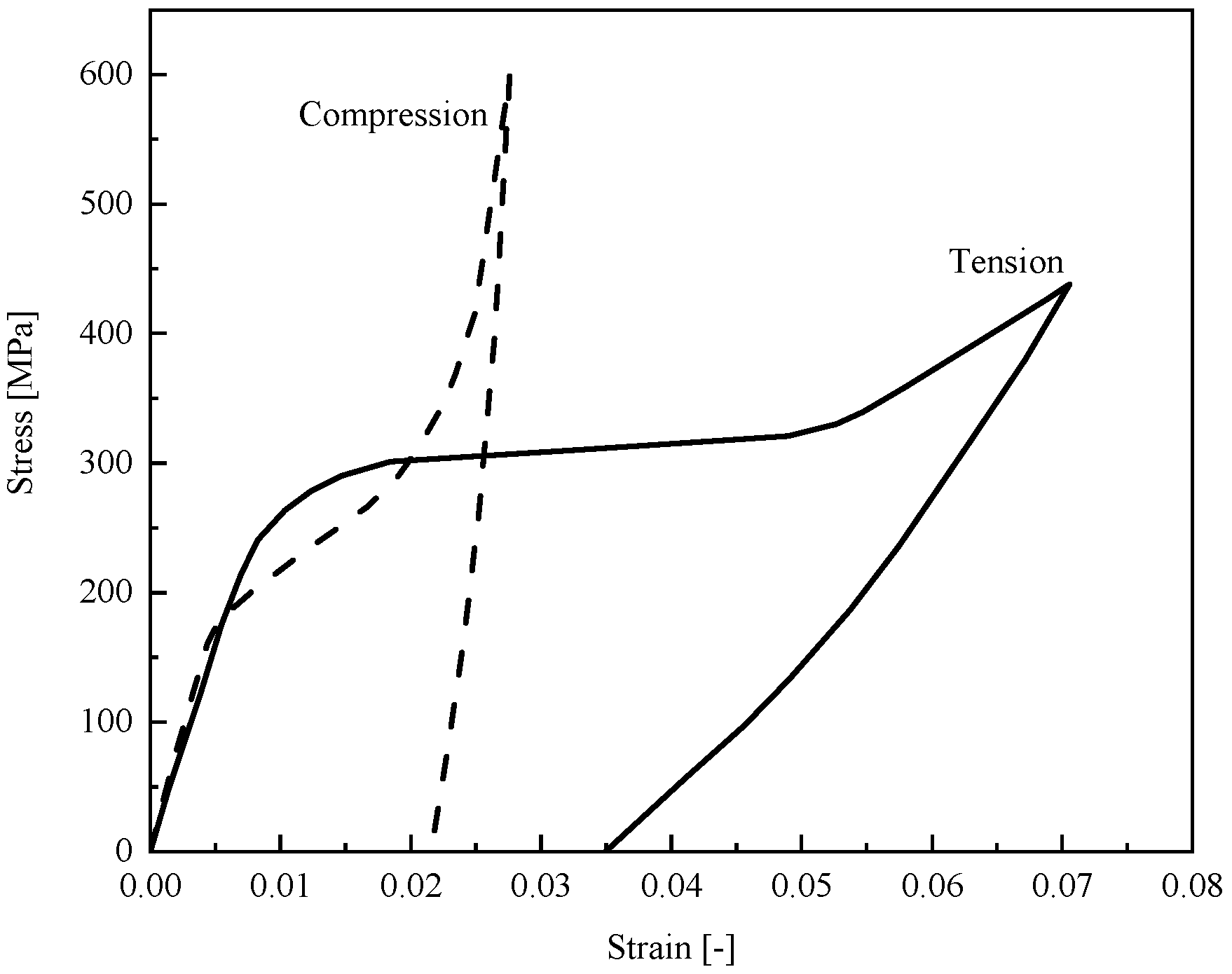
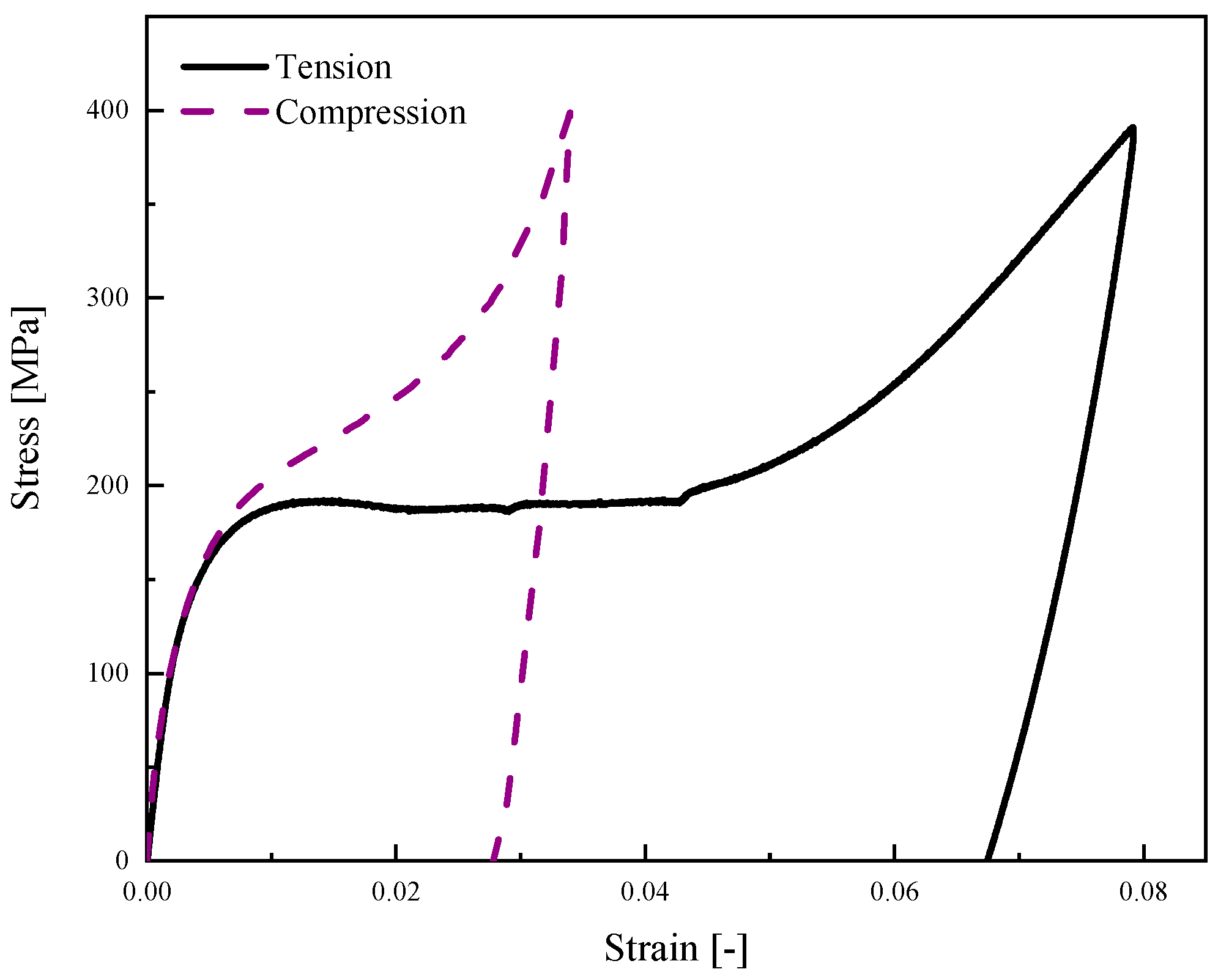
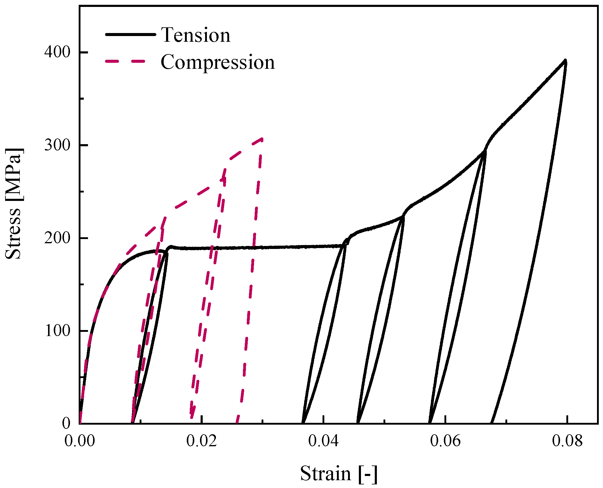
Among the existing theoretical models for bending problem, most cases are dedicated to analyzing the flexural response of the PE beams. But experimental data reported in [36] (Figure 1) also proves the significant importance of asymmetric behavior in tension and compression for SMA at low temperatures. Although some researchers [21,37,38,39,40] have proposed appropriate phenomenological models which are capable to describe non-symmetric response in tension and compression, investigation of the bending behavior of SME beams which analytically addresses asymmetric response of martensite phase in tension and compression has not been reported yet.
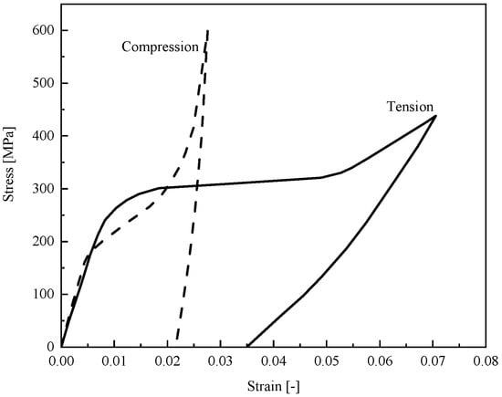
Figure 1.
Experimental tension and compression responses for SMA beam at low temperature [36].
Employing the existing tension–compression asymmetric models seem well-adapted for numerical simulations; however, they could be complex enough to derive analytical solutions for predicting beam deflection under transverse loading. In addition, those with close-form potential solutions have not considered any important secondary effects for bending problem, such as diverse hardening in detwinning zones as well as different elastic modulus during loading and unloading in detwinned martensite zones in tension and compression. Thus, in this paper based on the experimental data reported in [36], a parametric model is proposed to enable a precise description of asymmetric stress–strain behavior in loading and unloading. Then the bending behavior of SMA beams at low temperatures with both analytical and experimental approaches is studied. Employing the parametric model and according to Euler-Bernoulli beam theory, critical curvatures upon initiation of each zone in tension and compression are obtained. Moreover, moment–curvature relationships of an SME beam subjected to pure bending problem are derived. Based on the provided solution for pure bending, we expand our work to acquire governing equations of an SMA beam subjected to an arbitrary transverse loading. Furthermore, the deflection along the beam length is obtained for several beams with different cross-sections. To validate the results of this work, we have experimentally conducted several three- and four-point bending tests for rectangular and circular SMA beams. This study is structured as follows. Section 2 represents goals and objectives of this study. In Section 3, a parametric model is proposed to describe the asymmetric behavior of martensite SMA in tension and compression. The relationship between moment and curvature as well as the distance of neutral fiber from the centerline during loading is discussed in Section 4. Then in Section 5, considering the reverse detwinning process during unloading, we capture the relationship between stress and height of the beam which results in twelve different unloading states. Using semi-analytical method, pure bending equations are developed for an SMA beam under transverse loading in Section 6, which addresses the beam deflection along the length. Section 7 offers the experimental tests conducted for tensile, compressive, and bending as for finding out mechanical characterizations of SMA as well as differential scanning calorimetry test to determine phase transformation temperatures. Several bending cases are solved in Section 8, and then analytical results are compared with experimental data. In the last section, we finally provide a summary and draw conclusions.
2. Goals and Objectives of the Study
As stated in Section 1, most of the analytical studies on the bending of SMA beams are dedicated to superelastic features as well as austenite phase, however, martensitic beams attracted less attention and only have considered pure bending problem with symmetric material behavior. For this purpose, considering asymmetric tension and compression response with careful attention to all asymmetric behavior presented in Section 4 and Section 5, general bending of SME beam under transverse loading is derived and the relationship between beam deflection–length and moment–curvature during loading and unloading for rectangular and circular beams is obtained using polynomial approximation function and then compared with the experimental data as well as numerical results. Proposing explicit expressions for bending of SME beam empowers the designer to simply determine beam deflection and stress distribution along the SME beam when applied arbitrary transverse loading in general bending problem.
3. Parametric Model to Describe Asymmetric Tension-Compression Behavior in Martensite Phase
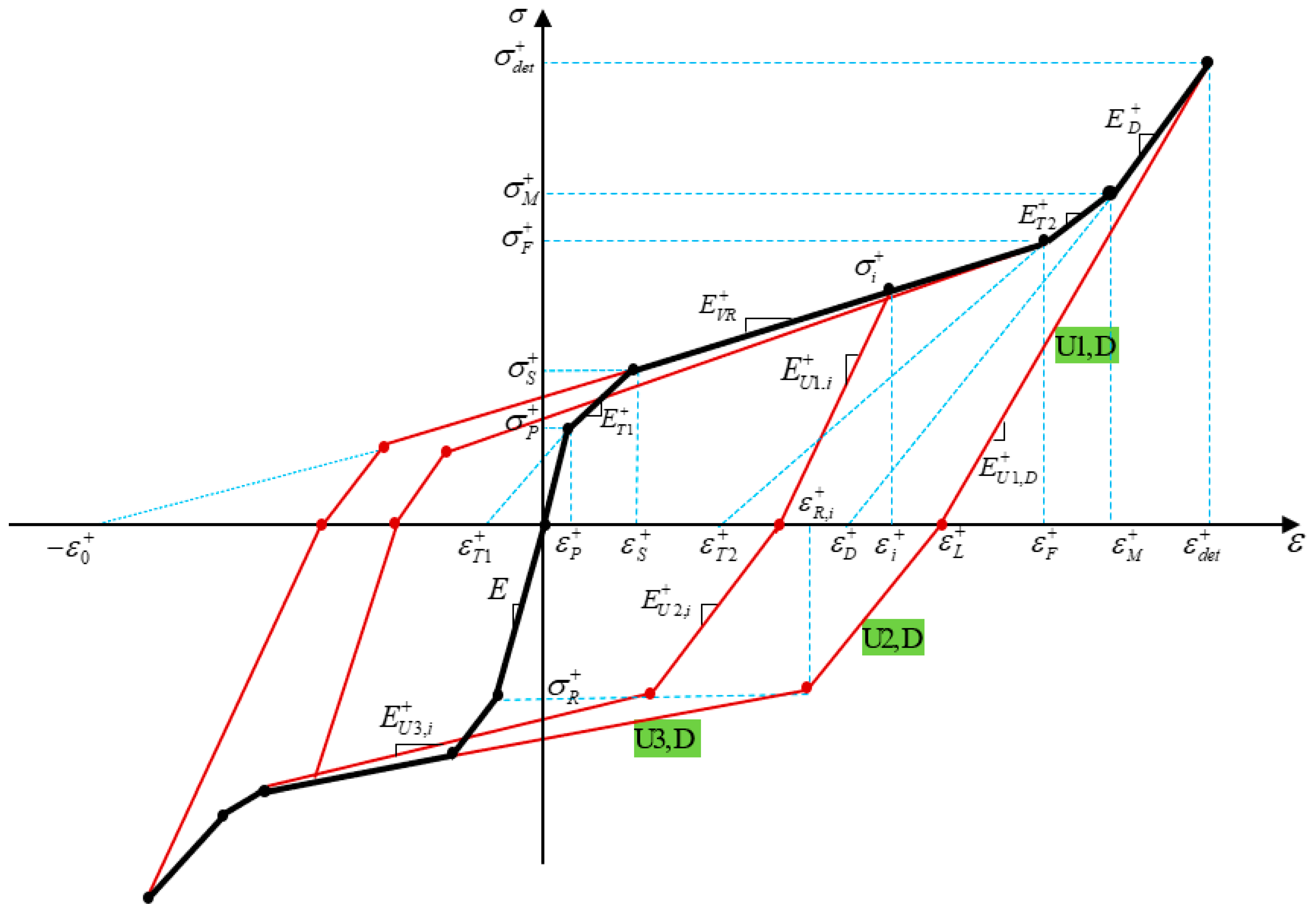
Motivated by one-dimensional SMA model proposed by Auricchio et al. [37] at low temperature, we present a parametric model for martensitic SMA beams to describe material behavior with asymmetric tension–compression response. This simplified one-dimensional parametric model enables us to derive bending behavior and predict the SMA beam deflection analytically. Material parameters in tension and compression are denoted with superscripts + and −, respectively. For more clarity and conciseness, Figure 2 only depicts the parameters in tension. For SME stress–strain curve in literatures, three different zones of twin (elastic), variant reorientation (VR-), and detwinned (D-) zones are generally defined. However, in this study to model the stress–strain curve more accurately, we have introduced and added two transient zones, namely T1- (elastic to VR-) zone and T2- (VR- to D-) zone. We express general one-dimensional constitutive relation as
where and are the Young modulus and transformation strain. Table 1 presents the material parameters related to each zone during loading in tension and compression. (j = 1, 2), , as well as , , and denote modulus of elasticity and transformation strain in Tj-, VR-, and D-zone, respectively. Moreover, the amounts of elastic moduli and transformation strains for each zone are determined and listed in Table 2. During loading, the stress and strain may exceed the maximum detwinning stress (strain) so that some fibers may be located in D zone. The stress and strain in this region are specified by and . Moreover, denotes the remained strain in the fiber upon unloading and it has the same value for all fibers in D zone.
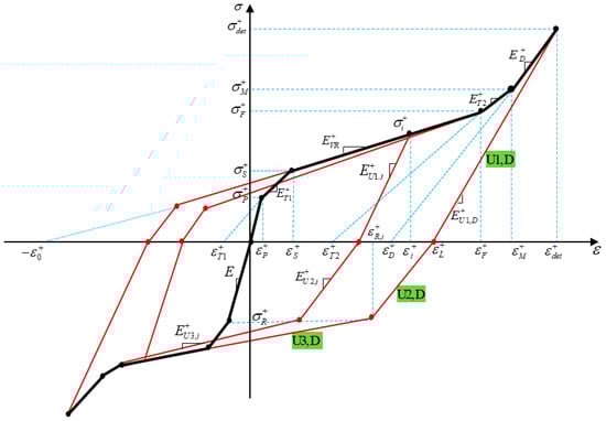
Figure 2.
Parametric model to describe the stress–strain relationship of SMA at low temperature.

Table 1.
Material parameters and constitutive equations related to each zone in tension and compression during loading.
Table 2.
Elastic modulus and transformation strain related to each zone.
In this model, to describe stress–strain behavior during unloading, we assume the unloading process (Figure 2) may consist of three parts as:
- Elastic unloading (U1);
- Stress reduction due to the reverse transient zone (U2);
- Stress reduction due to the reverse variant reorientation (U3).
Moreover, based on the experimental data reported in [36], unloading slope during phase transformation could be affected by the loading stress. Even in D-zone, the slope of unloading may not be coincident with the loading slope which is not considered in the proposed model by Auricchio et al. [37]. Accordingly, elastic modulus during unloading from fiber (, and ) can be modeled as
VR-zone:
where , and represent elastic moduli related to each part of unloading (U1, U2, and U3) in D-zone as:
D-zone:
can be obtained from Equation (2c). Moreover, and denote reverse VR start stress and strain, respectively. takes a constant value and for simplicity we consider it equal to . While could be a function of loading stress () and strain () which may be determined as:
4. Moment–Curvature Relationship in Loading
Using stress–strain curve represented in Figure 2 and based on Euler–Bernoulli beam theory in which beam cross-section remains plane during the elastic-plastic deformation, we derive an explicit relationship between bending moment and curvature during the loading procedure. Stress–height diagrams corresponding to each level of bending stress are schematically illustrated in Figure 3. In the most general cases, as the outmost fibers of tensile and compressive sides are located in detwinned zones, we can divide the cross-section into nine diverse regions as indicated in Figure 3e.
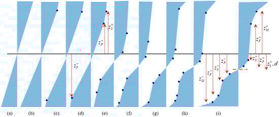
Figure 3.
Normal stress–height diagram during different phases of loading, fibers are located in (a) elastic zone, (b) T1-zone favored by tension, (c) T1-zone favored by compression, (d) VR-zone favored by tension, (e) VR-zone favored by compression, (f) T2-zone favored by compression, (g) T2-zone favored by tension, (h) D-zone favored by compression, (i) D-zone favored by tension.
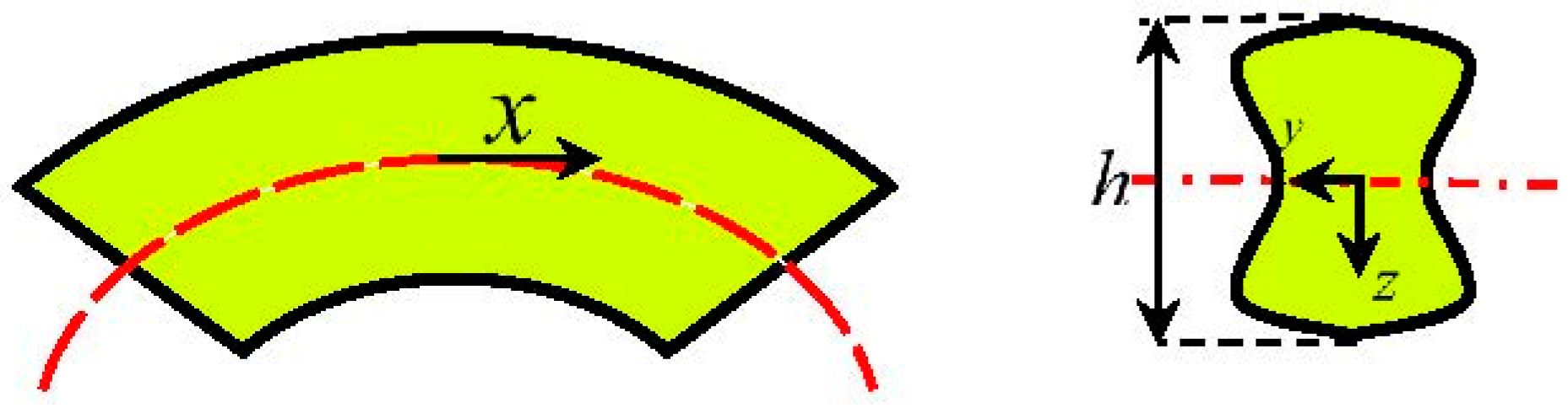
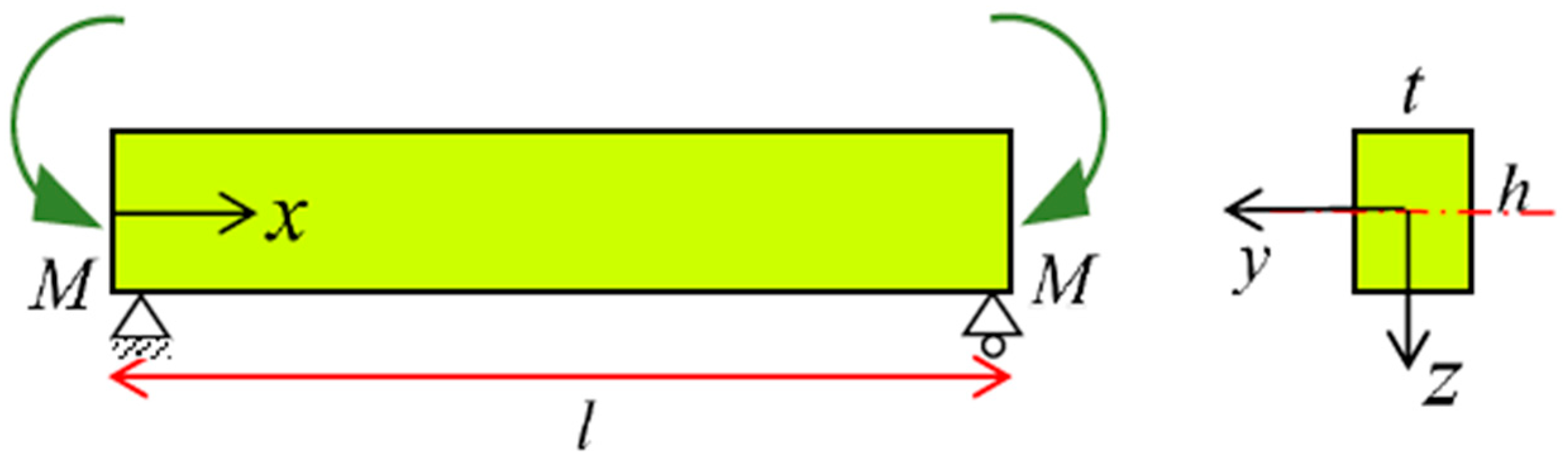
Due to the material parameters and asymmetric behavior of SMAs, the neutral axis of the beam will not be coincident with the centroid and may shift down or up concerning the centerline. Considering an arbitrary symmetric cross-section about y- and z-axes with maximum height h and thickness t (Figure 4), the moment–curvature relationship for the most general case is studied.
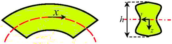
Figure 4.
Schematic of the SMA beam and its cross-section under bending.
Reminding Euler beam theory, the strain () and curvature () relationship can be expressed as:
where d represents the distance of neutral fiber from the centerline (z = 0). Due to the general asymmetric behavior of SMAs (Figure 1), we assume that is higher than (however, for the same process could be followed). Considering Figure 3a in which no detwinning process can occur, stress distribution still would be symmetric; thus, d is zero. Reaching stress of the outmost fiber maximum proportional stress in tension, the corresponding curvature () may be obtained as:
Exceeding may initiate T1-zone in tension, however, additional loading stress is required to start this process in the compressive region (Figure 3b); thus, we have
The unknown parameter of can be expressed in terms of and by satisfying the equilibrium of force (), which reads
where A represents beam cross section. When the stress in tensile and compressive side achieves , related curvatures to these stresses, respectively, yield
Then according to Figure 3c, the updated can be obtained as:
In Equations (8) and (10), are the distance between the centerline and the boundary of elastic and T1-zone in tension and compression; thus, using Equation (5) and Table 1, they can be obtained as
Further increase in applied load attributes more fibers in tension and/or compression experience VR-zone. Regarding Figure 1, finish stress of VR-zone in tension could be greater than compression (), however, for we can follow a similar procedure. Considering Figure 3e, and using Table 1, maximum curvature of VR-zone in tension and compression () may be written as:
Similar to Equation (10), we must refresh in terms of curvature as
where expresses the distance from the boundary of VR- and T2-zone in tension and compression. Thus, using Equation (5) and Table 1 they may be written as
Finally, achieving stresses in the outmost fibers in tension and compression (Figure 3g) causes the second transient zone (T2-zone) to begin developing in each side; thus, corresponding curvatures () are derived as
According to Figure 3i, and then employing applied bending moment for the most general loading case is obtained as
Furthermore, force equilibrium must be enforced to find the new amount of d as
To obtain the distance of boundary of T2- and D-zone in tension and compression from the centerline (), we first attain the height of VR-zones in tension and compression considering variant reorientation start and finish strains which could be expressed as
Thus, using Equations (14) and (18), may be determined as
Finally, considering half of the beam height, can be easily obtained as
5. Moment–Curvature Relationship in Unloading
While in the bending problem of SME beams, most of the researchers have considered stress reduction during unloading purely elastic, it has been proven that as elastic strains are recovered, reverse detwinning process may then occur [29]. However, in this study to increase the accuracy of the model, three unloading phases introduced in Section 2 are considered, so that fibers after elastic unloading go through the reverse transient zone as well as experience reverse variant reorientation.
For considering symmetric material behavior, it is assumed that in the unloading procedure, neutral fiber is located at the centroid. However, in the reality after unloading, neutral fiber may still gradually move up or down to satisfy force equilibrium. Therefore, to involve this effect in the present work, the stress distribution is considered asymmetric so that the distance of neutral fiber from the centerline upon unloading is represented by .
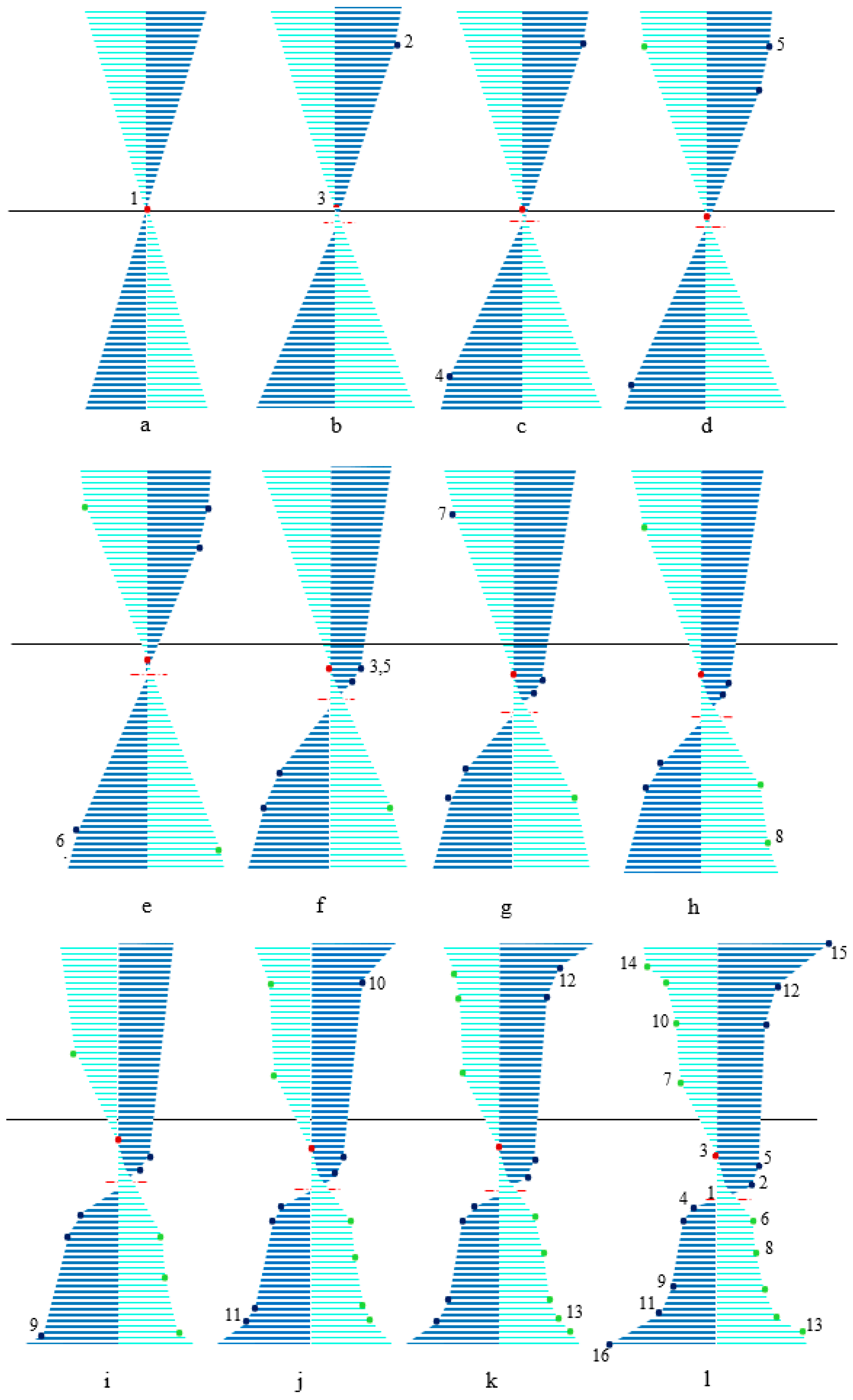
Unloading behavior is not only affected by the loading curvature but also by the asymmetric material behavior; the location of neutral fiber plays a significant role in capturing different forms of stress–height diagram during unloading. Generally, twelve unloading cases might be expected (Figure 5a–l). To elucidate the unloading procedure, stress–height diagram (Figure 5) and stress–strain curve (Figure 6) are numbered and individually described as below:

Figure 5.
Schematic of stress–height variations for an SMA beam at low temperature during unloading in (a) elastic zone, (b) T1-zone favored by tension, (c) T1-zone favored by compression, (d) VR-zone favored by tension, (e) VR-zone favored by compression, (f) when is coincident with , (g) due to reverse T-zone, (h) due to reverse VR-zone, (i) T2-zone favored by compression, (j) T2-zone favored by tension, (k) D-zone favored by compression, (l) D-zone favored by tension.
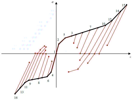
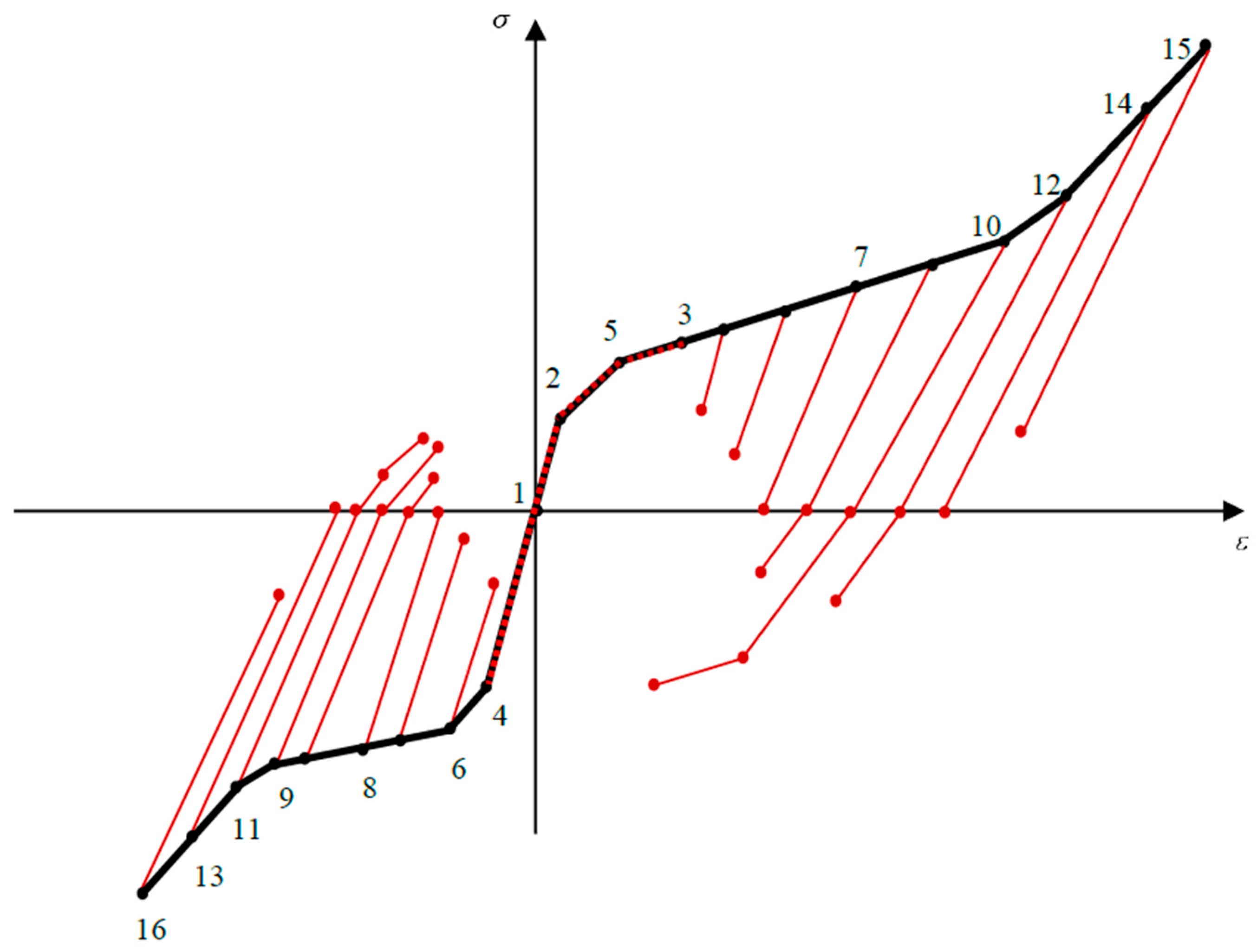
Figure 6.
Stress–strain curve for SMA beam at low temperature upon unloading.
- All fibers are in the elastic zone (Figure 5a); thus, the assumption of elastic unloading with the same modulus of elasticity (E) is reliable.
- In Figure 5b,c, respectively, some tensile () and compressive () fibers experience T1-zone while unloading is still symmetric with the slope of E.
- Initiation of VR-zone is favored by tension and compression (Figure 5d,e) so that upon unloading the modulus of elasticity is a function of loading stress; thus, each fiber has its own .
- Figure 5f describes a special position of , so that upon unloading it is coincident with . After this state, as unloading occurs some fibers reload with the slope of .
- Some fibers in VR-zone are favored by tension, in addition to elastic unloading, undergo stress reduction due to the reverse T-zone and reverse VR-zone and slopes, respectively (Figure 5g).
- According to Figure 5h, some fibers in VR-zone favored by compression, () unload with moduli of and in reverse T- and VR-zone, respectively.
- Once the compressive and tensile stresses exceed , it causes some fibers to enter into T2-zone and consequently stress releases similar to case 6. Moreover, we anticipate some fibers sit in single variant zones follow the same trend, however, in this case, slope of unloading for reverse T- and VR-zones are and , respectively (Figure 5i,j).
- Further proceeding into a single variant favored by tension and/or compression (Figure 5k,l), purely elastic unloading reappears during stress releasing.
Figure 5 indicates the most general case where all unloading states can simultaneously occur. To set out in detail, Figure 6 clarifies how unloading process can act as below:
Elastic unloading for paths 3–7 and 14–15 in tension, as well as 1–4, 4–6, 6–8, and 13–16 in compression.
- Reloading for points 1–2, 2–5, and 5–3 in tension.
- After elastic unloading fibers between points 7–10 and 10–12 in tension as well as 8–9 and 9–11 in compression have increasing trend in reverse T- and VR-zones.
- Fibers between 12–14 and 11–13 in tension and compression, respectively, suffer from a decreasing trend in reverse T- and VR-zones.
According to the above discussion, released stresses for can be decomposed into elastic unloading (), stress reduction due to the reverse T- () and VR-zone (), as
Thus, bending moment during unloading may be expressed as
As mentioned, and are the loading stress in tension and compression, respectively. To determine bending moment, it is required to obtain the unknown parameters of stress (, and ) and height ( or , , , and ), however, other parameters of height have just been specified from loading section. Due to the complexity of behavior, unknown parameters of stress and height may be initially derived in terms of (or ) and curvature reduction (), then to obtain , we employ force equilibrium equation to express in terms of . Unknown stress parameters can be related to using strain expressions; thus, considering Equation (5) and strain-intercept during unloading we may write as
According to Equation (21), we decompose strain reduction for , into elastic strain reduction (), strain reduction due to the reverse transient () and variant reorientation zones () parts, as
Regarding the process of unloading described in Figure 6, we express as
Using Table 1 for each region and then substituting Equations (5) and (25) into Equation (24), as well as employing and , we may finally write as
Furthermore, reloading for points 2 to 3 attributes to stress increase in VR-zone; thus, using Equation (23) it yields
To derive , it should be considered that point 7 is exposed to experience reverse variant reorientation during unloading, so that at this moment is still zero and reach ; thus, using Equations (21) and (24) we have
Inserting the constitutive equation of VR-zone (Table 1) and Equations (2a) into (2b), can be determined in terms of . Then substituting Equations (23) and (25) into (28) and after some mathematical manipulations, we achieve a polynomial expression in terms of as
where , and can be expressed as
The fiber at point 14 during unloading has arrived at zero stress level (); thus, only elastic portion of Equation (21) exists. Employing , Equation (5) as well as considering constitutive relation of D-zone in tension (Table 1), may be given as
In a similar approach, we can determine and , however, corresponding parameters to compressive side in Equations (29)–(31) must be considered. Finally, balancing the equilibrium of force in Figure 5i, leads to derivation of in terms of as
All unknown parameters thus far have been just expressed in terms of curvature reduction which may be calculated by fulfilling .
6. Expanding Pure Bending Approach to Determine Beam Deflection in General Bending
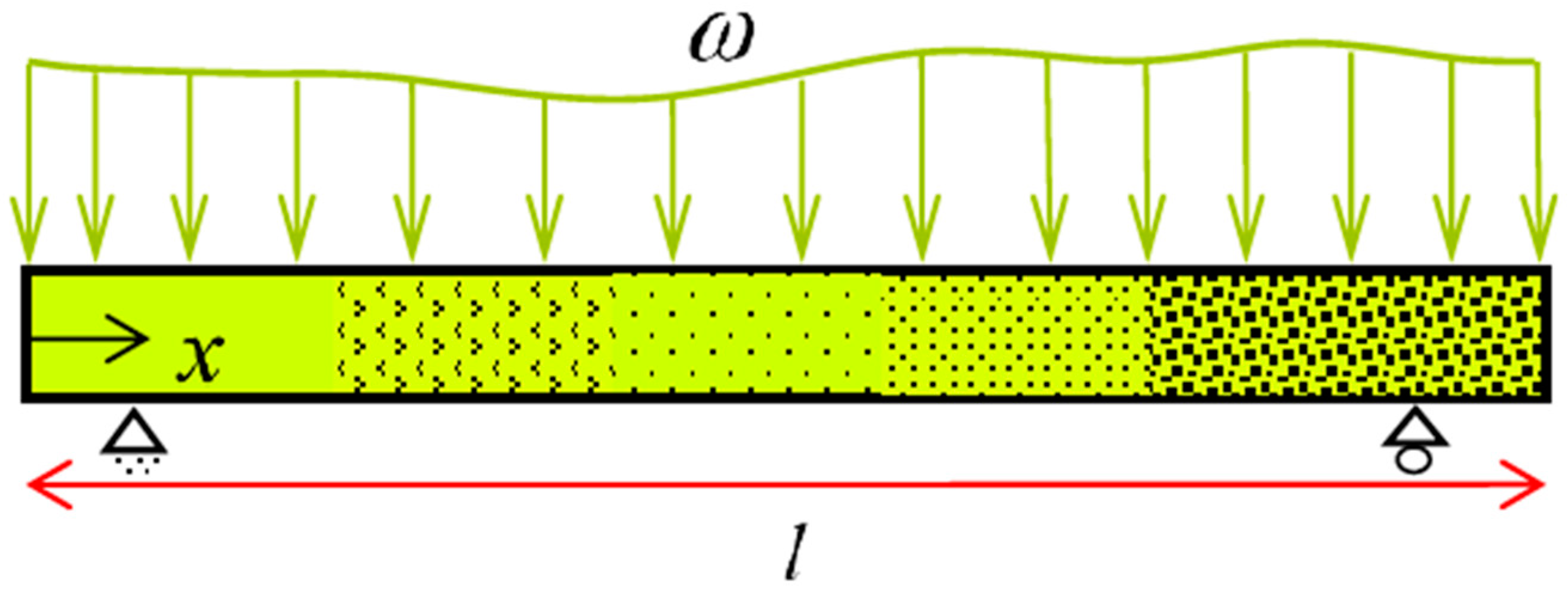
Ostadrahimi et al. in [28] proposed an analytical solution based on the pure bending problem to achieve beam deflection. As for bending moment depends on the beam length, each cross-section represents a pure bending problem. Accordingly, for a beam with an arbitrary transverse loading, we initially derive bending moment for a cross-section. Employing polynomial approximation function, curvature may be subsequently expressed in terms of the SMA beam length. Considering a beam under transverse loading (Figure 7), it is expected to create nine types of cross-sections based on the stress–strain curve. However, for simplicity we consider elastic, VR- and D-zones in tension and compression, thus five types of cross-sections can be generated.

Figure 7.
A prismatic SMA beam subjected to transverse loading (general bending).
- All fiber in the elastic zone.
- Some fibers are in VR-zone favored by tension (compression).
- VR-zones in both tension and compression sides have occurred.
- Some fibers are in D-zone favored by tension (compression).
- On both sides, D-zone can happen.
Moreover, (i = 1–5) indicates the corresponding length to each type of cross-sections, so that they can be derived when the bending moment is determined. As small deflection is assumed, we replace in Equation (22), leading to a nonlinear differential equation as a function of deflection. To solve this differential equation via a semi-analytical approach, a polynomial approximation function is employed to propose the beam curvature as
where denotes the polynomial maximum degree. To obtain to , we substitute Equation (33) into Equation (22) and then equate coefficients of to on both sides. Integrating Equation (33), deflection along the length () is finally represented as:
Imposing appropriate boundary conditions, we may determine integration constants of and .
7. Experimental Tests
Most of the previous experimental studies on SMA bending problem are focused on the behavior of superelastic beams while in this work, several experimental bending tests with different cross-sections have been conducted to broaden the physical understanding of martensitic beams under bending behavior and compare experimental data with the proposed analytical solution.
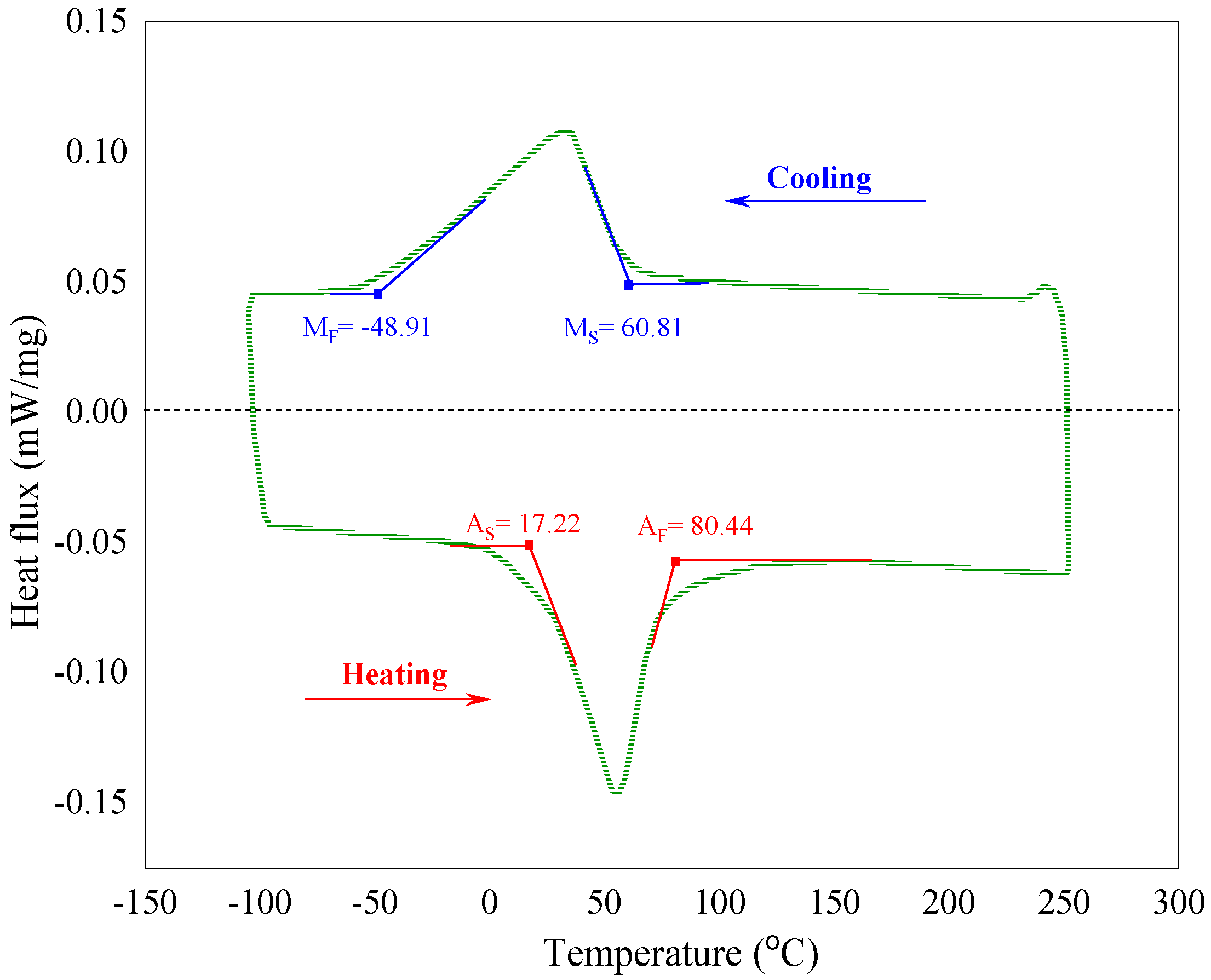
To find out material properties and mechanical characterizations of the NiTi alloy (Ni: 53 wt%, Ti: 47 wt%) martensitic beam, we have initially measured transformation temperatures through differential scanning calorimetry (DSC) test, indicated in Figure 8; MS, MF, AS, and AF are, respectively, martensite and austenite start and finish temperatures.
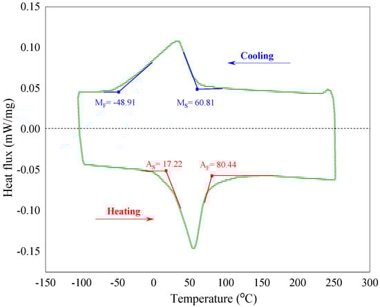
Figure 8.
DSC curves of the martensite SMA beam.
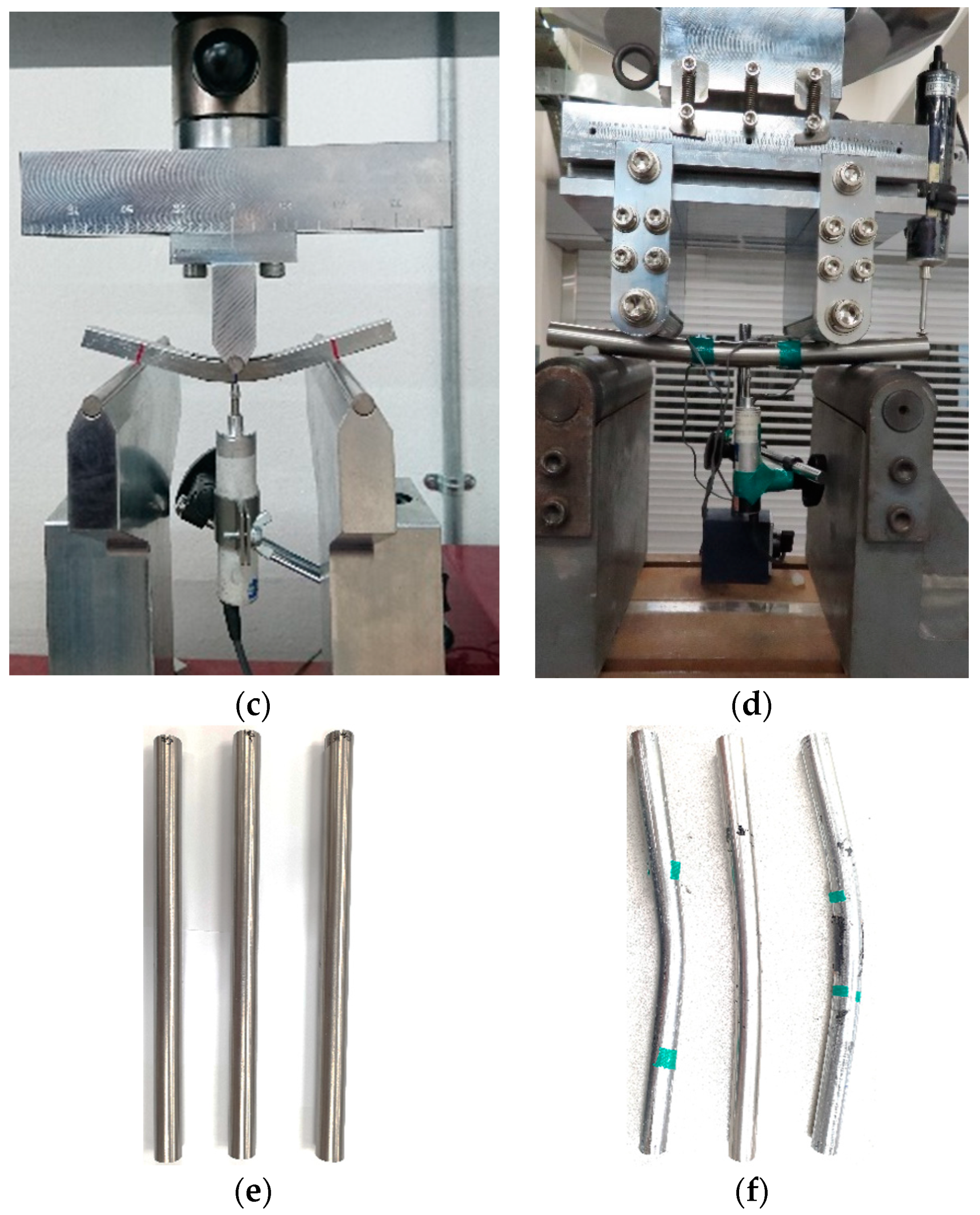
According to the ASTM E8/E8M-16AE1 and E9-19 (2016), several standard samples are fabricated, and then using the Universal Test Machine (UTM), tensile and compressive tests are carried out to determine the stress–strain behavior (Figure 9a,b). Furthermore, three prismatic beams with circular (diameter 20 mm and length 300 mm) and two rectangular cross-sections (height 10 mm, thickness 14 mm and length 100 mm) are subjected to three- and four-points bending tests to measure the force–deflection relationship at different conditions (Figure 9c,d). All experiments have been performed under displacement control and at the speed of 1 mm/min. Note that, the manufacturer, model, and country of test device, respectively, for DSC are NETZSCH, LFA 467, Selb, Germany, and for tensile, compressive, and bending tests is MTS, 500 kN-370.50, Eden Prairie, MN, USA.
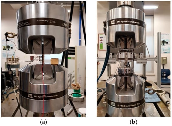
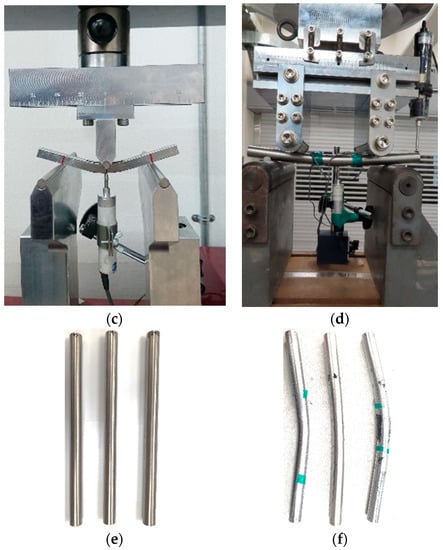
Figure 9.
Experimental tests setup. (a) Tensile test, (b) compression test, (c) bending test for rectangular beam, (d) bending test for circular beam, (e) circular beams before bending tests, (f) after bending tests.
8. Experimental Data and Numerical Results
Several case studies are investigated in this section for martensitic SMA beams with rectangular and circular cross-sections. To this end, we have derived pure bending equations for martensitic beams and presented moment–curvature and force–displacement relationships under diverse loading conditions. Moreover, general bending equations based on the pure bending problem have been obtained by considering a cantilever beam. To validate the current work, we initially compared the results of the pure bending problem with the finite element method using ABAQUS software 6.14, Paris, France in which symmetric material behavior is assumed. Then the analytical results for martensitic beams while having different responses in tension and compression are compared with experimental data from three- and four-point bending tests.
Example1: Pure bending problem with a rectangular cross-section.
A rectangular beam of with t, height h, and length l under pure bending condition has been considered in Figure 10. Using the analytical solution in Section 3 and Section 4, Table 3 presents loading and unloading force and moment–curvature relationships for a rectangular martensite SMA beam.

Figure 10.
Rectangular beam subjected to the pure bending.
Table 3.
General moment and force equations for the rectangular beam subjected to the pure bending problem.
In this example, we first consider symmetric material properties for SMA beam to compare the results of current work with the results of three-dimensional SMA continuum elements [3]. To simulate symmetric material properties by the finite element method, a user-defined material subroutine (UMAT) has been implemented into the finite element software ABAQUS. Table 4 reports the geometrical and material parameters of this case study.
Table 4.
Model parameters of the SMA beam.
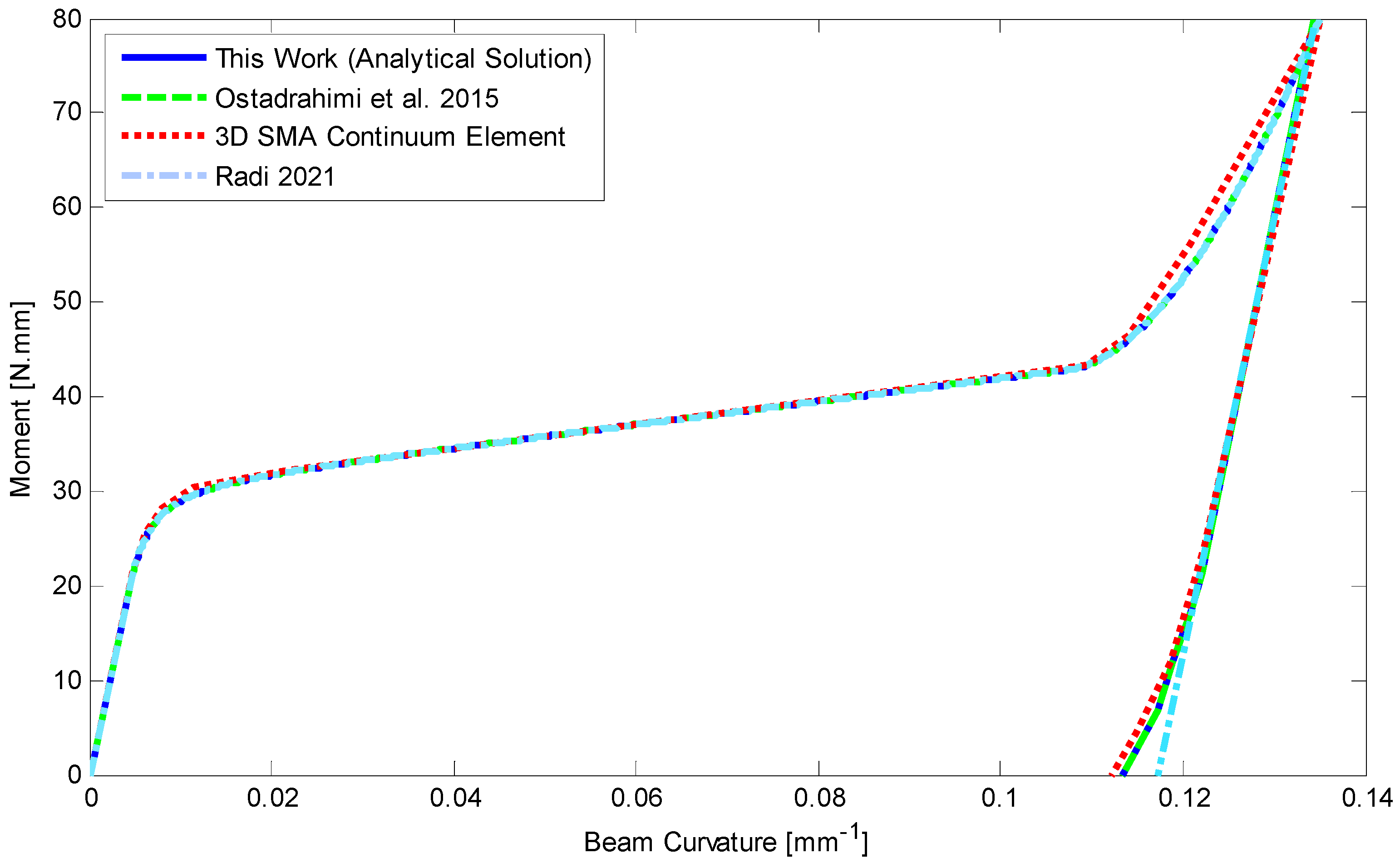
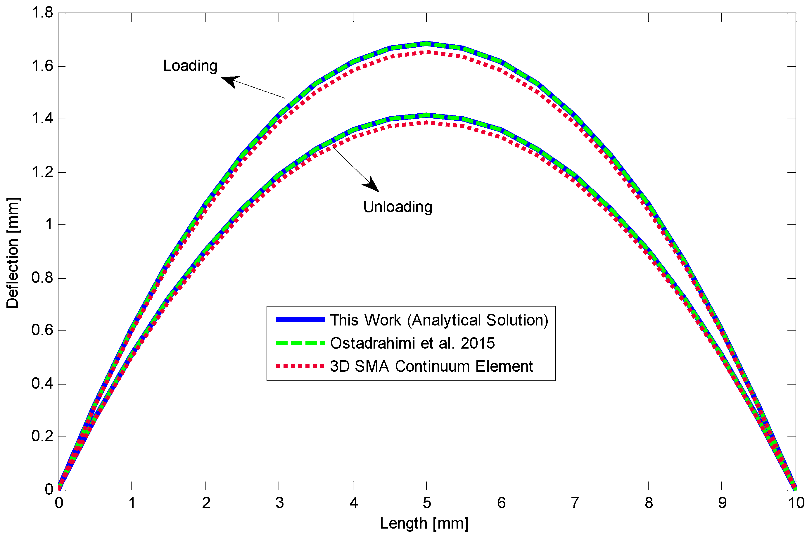
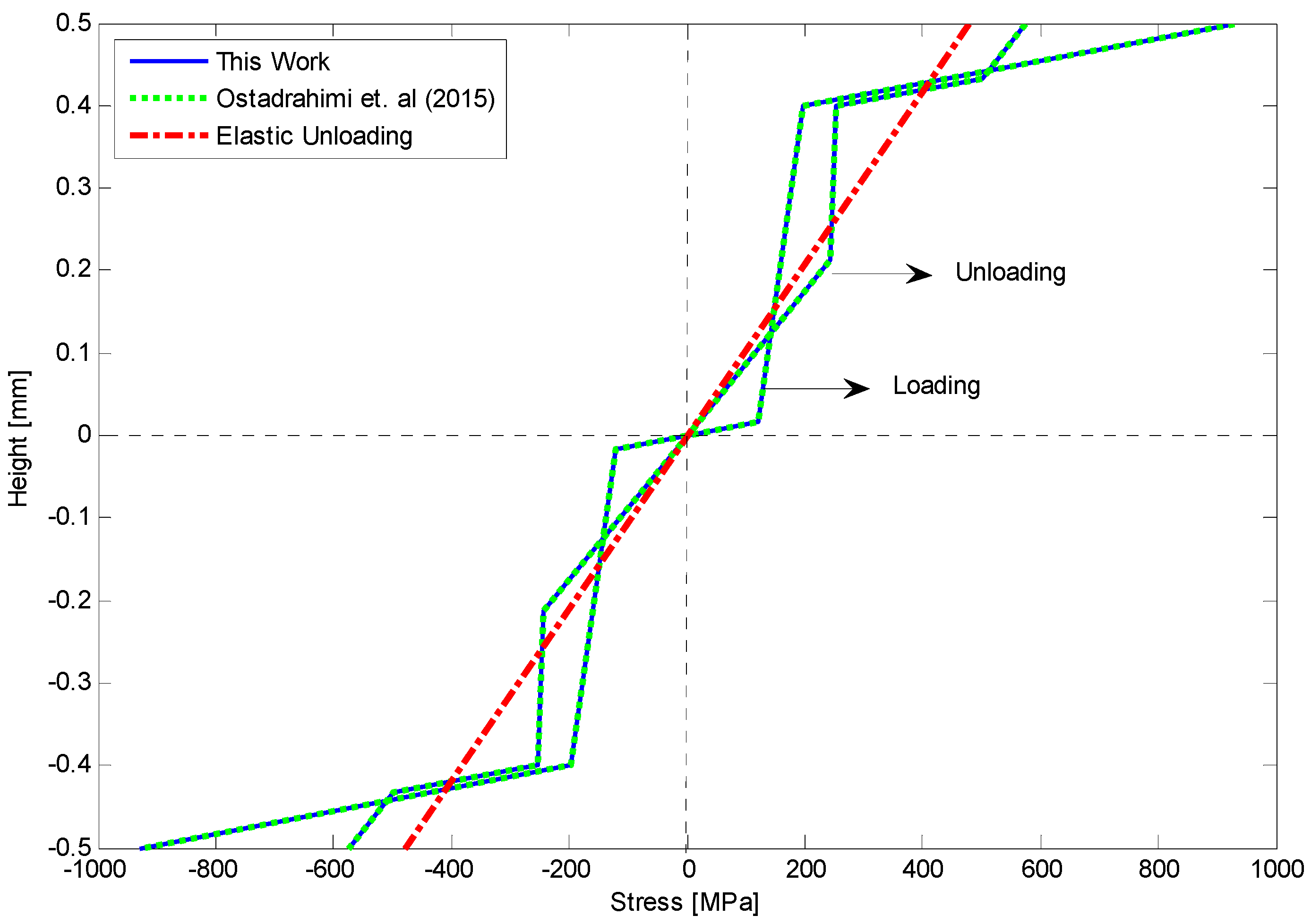
The moment–curvature relationship is depicted in Figure 11 as a moment of 80 N mm has been applied to the beam. Furthermore, Figure 12 shows deflection along the length of SMA beam during loading and unloading. The beam remains deflected about 1.4 mm at the middle part. A good agreement is achieved for analytical results comparing with the finite element method. We also provide stress–height diagram for this case during loading and unloading in Figure 13. Since the material parameters are assumed symmetric and transient zones have not been considered, stress distribution is symmetric as well and three different regions can just appear.
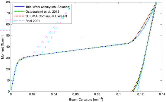
Figure 11.
Comparison of analytical results considering symmetric material parameters and finite element for a rectangular SMA beam subjected to a moment of 80 N.mm at −40 °C, [28,35].

Figure 12.
Deflection versus length of the SMA beam with symmetric material properties in loading and unloading [28].
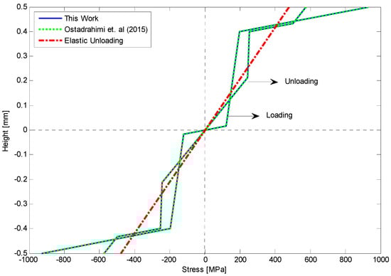
Figure 13.
Comparison of stress–height relationship upon loading and unloading with elastic unloading for pure bending problem with symmetric tension–compression response [28].
Example2: three-point bending test.
In this case study, we have experimentally conducted uniaxial loading–unloading tests (Figure 9a,b) to identify the mechanical properties of Ni-Ti SMA specimens at room temperature (Figure 14). To elucidate the SMA behavior during loading and unloading in variant reorientation zones, we have also conducted two hysteric tests under tensile and compressive forces (Figure 15). According to these experimental tests, the material parameters are presented in Table 5.
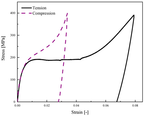
Figure 14.
Monotonic tensile and compression tests for martensite SMA beam at room temperature.

Figure 15.
Hysteric tensile and compression tests for martensite SMA beam at room temperature.
Table 5.
Material properties extracted from experimental tests.
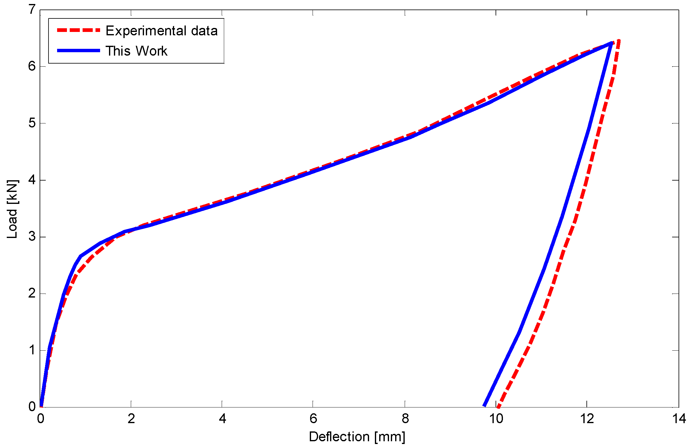
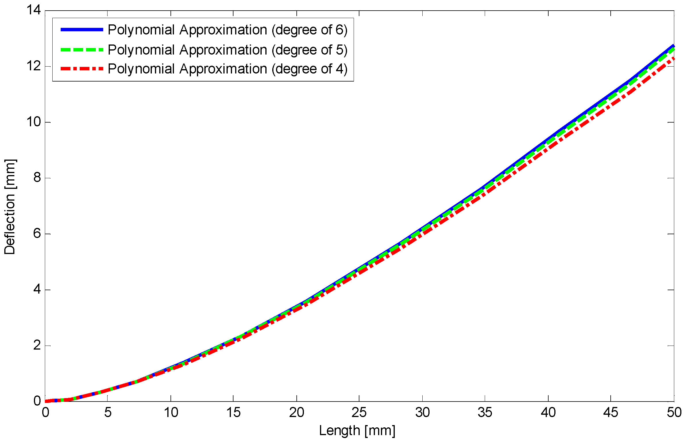
After specifying SMA properties, a rectangular beam (10 mm height, 14 mm width) is simply supported at its ends (Figure 9c). Then a three-point bending test with the lower span length of 100 mm and a force of 6.5 kN in the middle section is performed at room temperature. Considering half of the three-point bending problem (Figure 16) and using the equations of Section 5 as well as employing finite difference method (FDM) the load–deflection relationship is illustrated in Figure 17. The maximum difference between current results and experimental data is about 4% in unloading stage. Furthermore, using polynomial approximate functions the relationship between load and deflection for different degrees of the polynomial including 4, 5, and 6 are depicted in Figure 18. It indicates that for degrees of 5 and 6 the results have converged in almost a specific value. However, in a degree of 4 there is about 6% difference compared to the higher degrees, it is still in a good agreement with them.
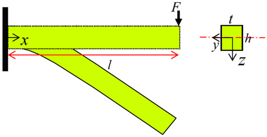
Figure 16.
The cantilever (half of the three-point bending model) beam subjected to transverse loading at free end.
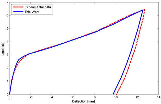
Figure 17.
Comparison of load and deflection for a rectangular SMA beam subjected to the three-point bending test at room temperature.

Figure 18.
Comparison of different degrees of polynomial approximation function for deflection of SMA beam along the length.
Example 3: four-point bending tests.
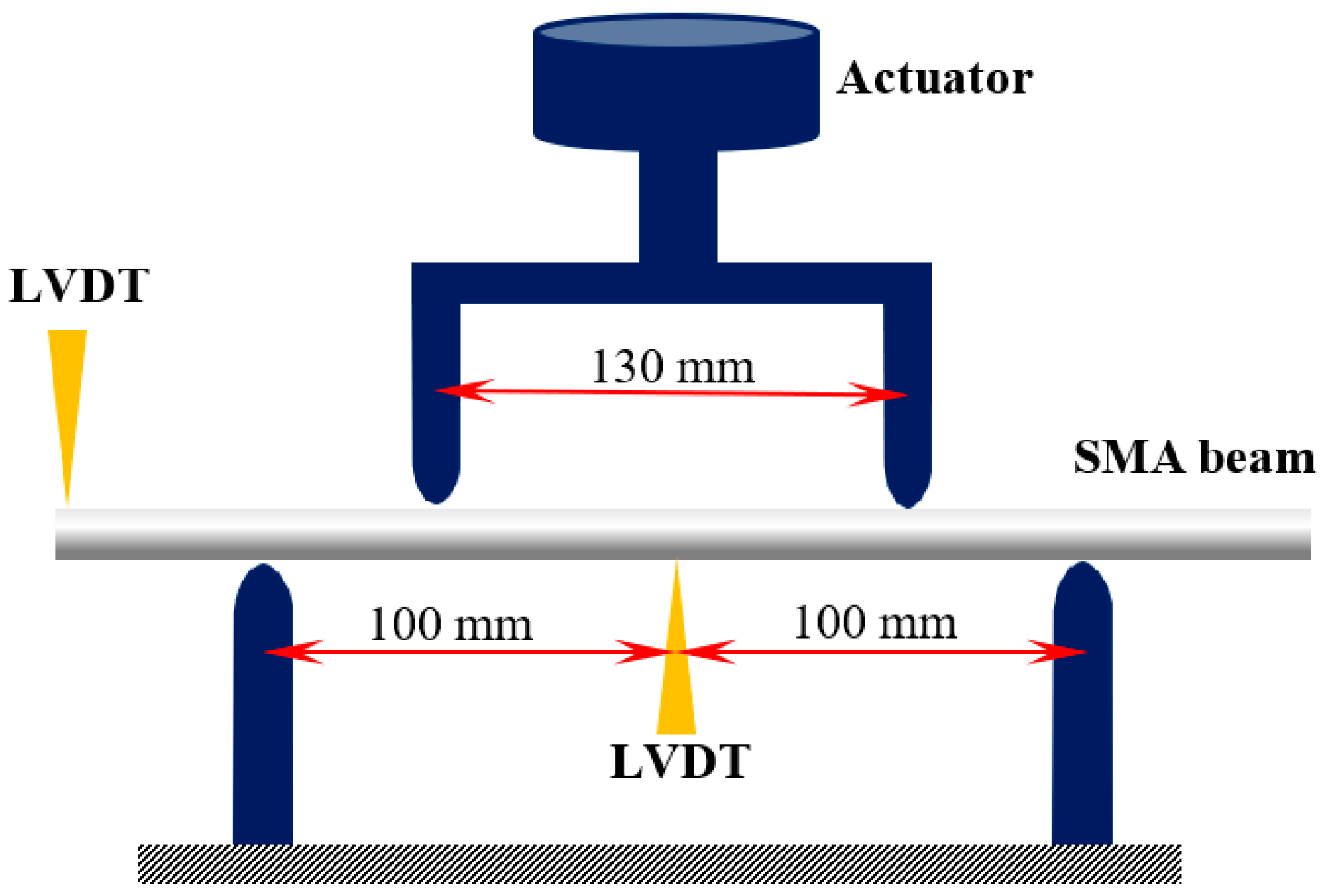
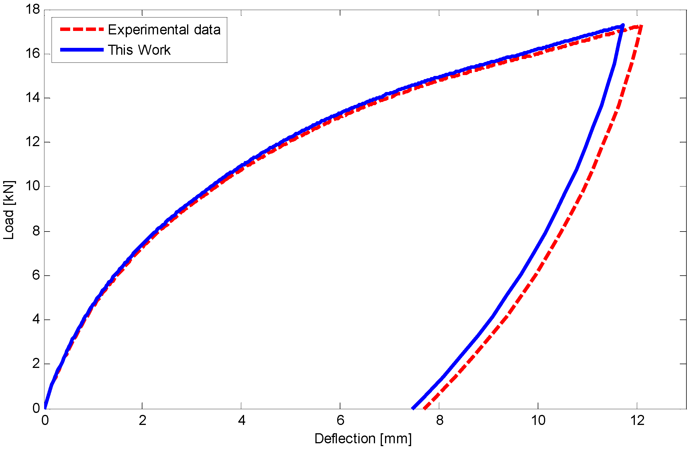
According to ASTM E855 − 08, we have finally conducted two four-point bending tests under different applied load for circular beams. The test specimens have a length and diameter of 300 and 20 mm, respectively. The distance between loading and supporting points are 130 and 200 mm (Figure 19). Two LVDTs (linear variable displacement transducer) are installed at the center and one end of the beam to measure the displacement. To assess the bending behavior of the SMA beam under bending before initiation of T- and D-zones favored by tension, applied loads in the first and second tests are, respectively, about 17 and 19 kN.

Figure 19.
Dimension and schematically experimental setup for four-point bending tests.
Using equations in Section 5 and FDM, the load–deflection relationship for the first and second four-point tests has been illustrated in Figure 20 and Figure 21, respectively. There is a good agreement between the results of this work and experimental data. It is worth noting that a maximum 5% difference upon unloading may refer to some simplifications which have been considered in unloading stages.

Figure 20.
Comparison of load versus deflection for a circular SMA beam under four-point bending test with force of 17 kN at room temperature.
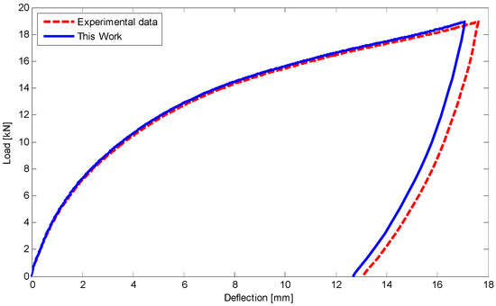
Figure 21.
Comparison of load versus deflection for a circular SMA beam subjected to four-point bending test with force about 19 kN at room temperature.
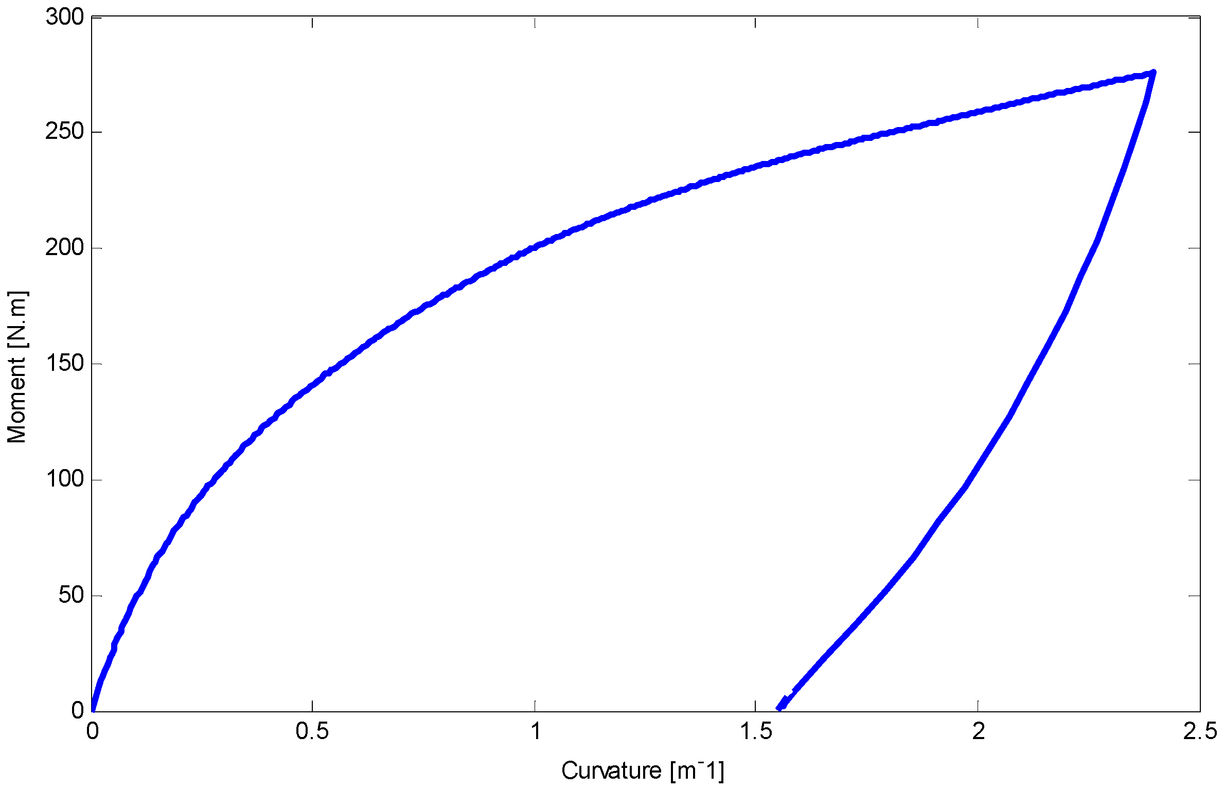
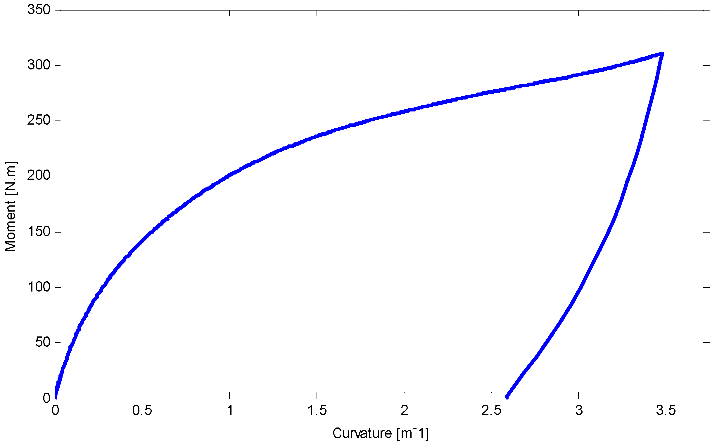
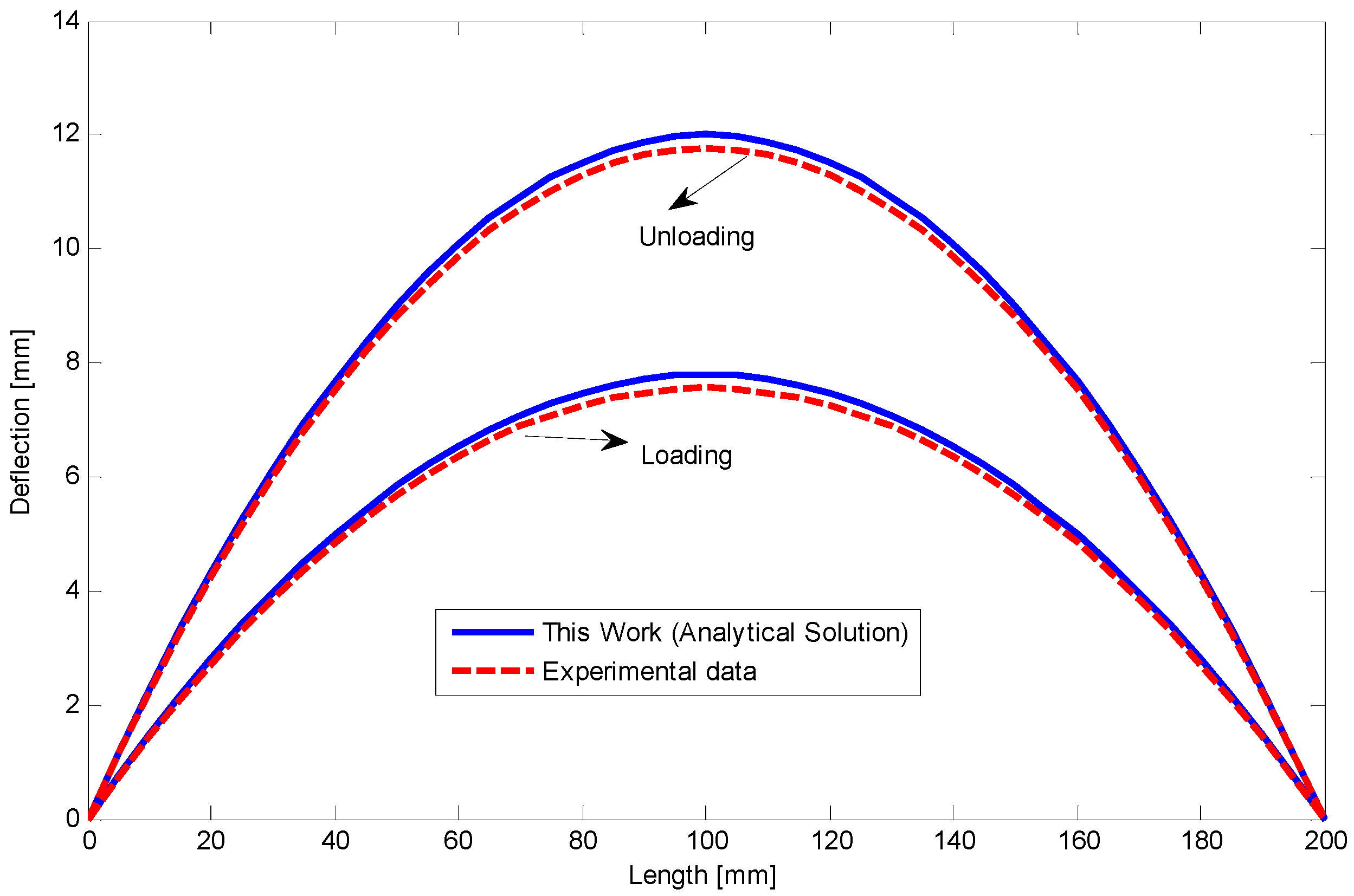
The relationship between moment and curvature for both tests are shown in Figure 22 and Figure 23. The curvature about 3 m−1 may approximately be near to the required stress to initiate D-zone favored by tension (). Making progress in loading stages can increase the slope of moment–curvature relationship. Furthermore, employing Equations (33) and (34), deflection of the SMA beams along the length during loading and unloading stages are determined and indicated in Figure 24 and Figure 25 for first and second four-point bending tests, respectively.

Figure 22.
The relationship between curvature and moment for the circular SMA beam under four-point bending test with the force of 17 kN at room temperature.
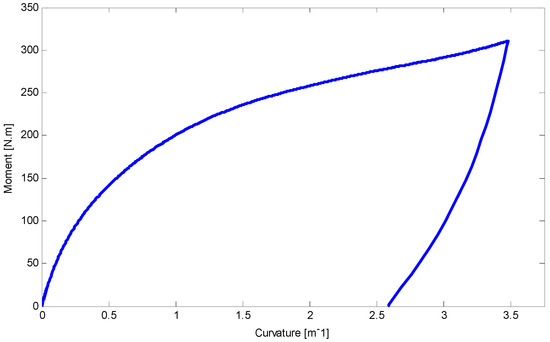
Figure 23.
Curvature and moment relationship for the circular SMA beam subjected to four-point bending test with the force about 19 kN at room temperature.
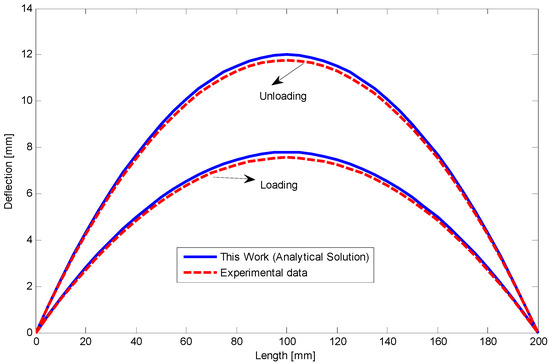
Figure 24.
The relationship between deflection and length at the end of loading and unloading for the circular SMA beam under four-point bending test with the force of 17 kN.
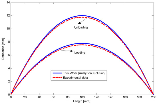
Figure 25.
The relationship between deflection and length at the end of loading and unloading for the circular SMA beam under four-point bending test with the force about 19 kN.
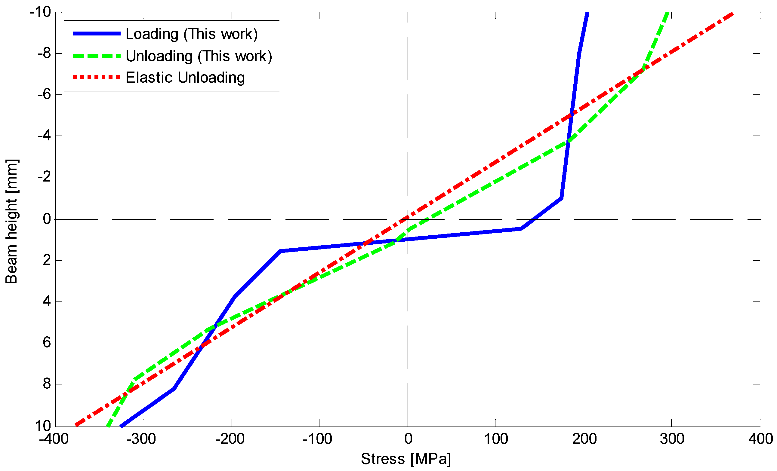
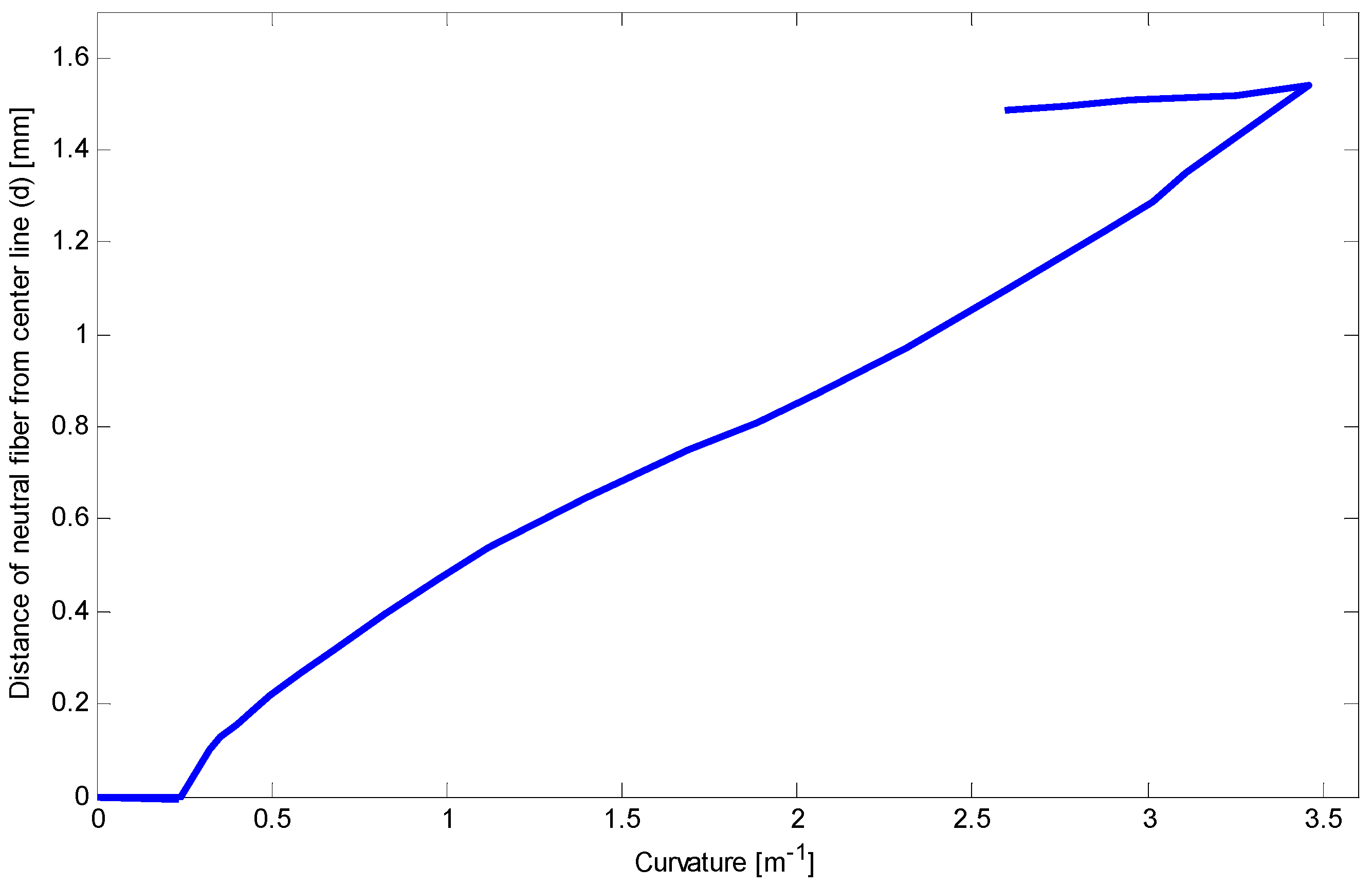
Because of safety, we stopped loading at the curvature about 3.5 m−1. To clarify stress–strain behavior of the SMA at this curvature, bending stress during loading and at the end of unloading are obtained and depicted in Figure 26. It shows that most of the fibers in the compressive side are located in D-zone, and some fibers on opposite side are exposed to experience D-zone favored by tension. Upon unloading, comparing the bending stress of present work with general elastic unloading reveals a marked difference between the two theories. It also emphasizes how considering reverse phase transformation during unloading can affect bending behavior of the SME beams. Finally, Figure 27 illustrates the variations of the neutral fiber from the centerline in loading and unloading. It is clear that at the beginning of loading and before reaching stress or , stress distribution is totally symmetric. Upon initiation of the detwinning process in tension and then compression sides, the neutral fiber starts moving away from the centroid. Subsequently, more increase in the beam curvature leads to further distance from the centerline. However, the unloading process subtly brings this fiber back to the centroid.
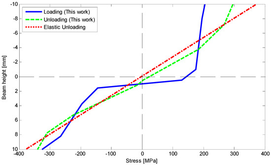
Figure 26.
Comparison of stress–height relationship upon loading and unloading with elastic unloading for four-point bending test.
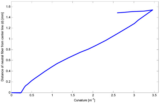
Figure 27.
Relationship between curvature and distance of neutral fiber from the centerline during loading and unloading.
9. Summary and Conclusions
This work has analytically and experimentally focused on the flexural behavior of prismatic SMA beams under arbitrary transverse loading. We employ the Euler–Bernouli beam theory and a parametric model to describe asymmetric response of an SMA beam in tension and compression as well as bending behavior. The parametric model provides different elastic properties in martensite twined and detwinned phases. Related equations are initially derived for a prismatic SMA beam under the pure bending problem. To capture general bending equations, we employ pure bending solution and semi-analytical methods. Deflection along the length of the beam can be obtained by using different degrees of polynomial approximation functions. To validate our analytical results, we have experimentally performed three- and four-point bending tests for various SMA beams with different cross-sections at low temperatures. Moment–curvature, stress–height, load–deflection, and variation of the neutral axis from the centerline are reported during loading and unloading. Considering symmetric material behavior, the present model is compared with the available numerical and analytical works, and the result shows an accurate agreement (less than 2% difference) in case of beam curvature and bending moment. Then to validate the effect of asymmetric parameters of our models in terms of predicting bending response of martensitic SMA beams, we initially conduct several three- and four-points bending tests. The obtained analytical results of this work when compared with experimental data in case of load–deflection and moment–curvature relationships show only about 6 and 5%, difference, respectively, proving the high accuracy of the derived governing equations for predicting the SMA beam behavior under general bending. These accurate results stem from assuming the reverse detwinning process during unloading as well as different slope of stress–strain curves when the beam fibers are under loading and unloading conditions. Moreover, this solution could study the distance of neutral fiber from center line during loading and unloading. Since in this paper, the stress–strain of each fiber along the beam height is tracked upon loading and unloading, and the corresponding stress–height diagram to applied bending moment are determined, a deeper practical and physical understanding on the bending problem of SMA beams at low temperatures is achieved. Furthermore, these governing equations can empower the designer to obtain beam deflection and stress distribution of SMA beam with consummate ease.
Author Contributions
Conceptualization, A.O.; methodology, A.O. and E.C.; software, A.O.; validation, A.O., F.T.-B. and E.C.; formal analysis, A.O.; investigation, A.O., E.C. and F.T.-B.; resources, E.C.; data curation, F.T.-B. and E.C.; writing—original draft preparation, A.O.; writing—review and editing, F.T.-B. and E.C.; visualization, A.O.; supervision, F.T.-B. and E.C.; project administration, A.O.; funding acquisition, E.C. All authors have read and agreed to the published version of the manuscript.
Funding
This work was supported by the National Research Foundation of Korea (NRF) grant funded by the Korea government (MSIT) (Project No. NRF 2020R1A4A-1018826).
Institutional Review Board Statement
Not applicable.
Informed Consent Statement
Not applicable.
Data Availability Statement
Not applicable.
Acknowledgments
The authors are immensely grateful to Jamal Arghavani, Associate Professor at Mechanical Engineering Department at Sharif University of Technology, Tehran, Iran, who has graciously contributed his time in shaping the main topic.
Conflicts of Interest
There is no conflict to declare. The final version of the manuscript has been approved by all authors.
References
- Lagoudas, D.C. Shape Memory Alloys: Modeling and Engineering Applications; Springer: New York, NY, USA, 2008; Available online: https://www.springer.com/gp/book/9780387476841 (accessed on 29 December 2019).
- Arghavani, J.; Auricchio, F.; Naghdabadi, R.; Sohrabpour, S. A 3-D phenomenological constitutive model for shape memory alloys under multiaxial loadings. Int. J. Plast. 2010, 26, 976–991. [Google Scholar] [CrossRef]
- Vahidi, S.; Arghavani, J.; Choi, E.; Ostadrahimi, A. Mechanical response of single and double-helix SMA wire ropes. Mech. Adv. Mater. Struct. 2021, in press. [Google Scholar] [CrossRef]
- Choi, E.; Ostadrahimi, A.; Youn, H. Analytical and experimental study of shape memory alloy reinforcement on the performance of butt-fusion welded joints in high-density polyethylene pipe. J. Intell. Mater. Syst. Struct. 2020, 31, 2029–2043. [Google Scholar] [CrossRef]
- Mirzaeifar, R.; DesRoches, R.; Yavari, A.; Gall, K. On superelastic bending of shape memory alloy beams. Int. J. Solids Struct. 2013, 50, 1664–1680. [Google Scholar] [CrossRef]
- Choi, E.; Ho, H.V.; Seo, J. Dynamic Behaviors of Mortar Reinforced with NiTi SMA Fibers under Impact Compressive Loading. Materials 2021, 14, 4933. [Google Scholar] [CrossRef] [PubMed]
- Ho, H.V.; Choi, E.; Kim, D.; Kang, J. Straining Behavior of Mortar Reinforced by Cold Drawn Crimped and Dog-Bone-Shaped Fibers under Monotonic and Cyclic Compressions. Materials 2021, 14, 1522. [Google Scholar] [CrossRef]
- Ho, H.V.; Choi, E.; Park, S.J. Investigating stress distribution of crimped SMA fibers during pullout behavior using experimental testing and a finite element model. Compos. Struct. 2021, 272, 114254. [Google Scholar] [CrossRef]
- Thier, M.; Mick, A.; Drescher, D.; Bourauel, C. Deformation behaviour of NiTi shape memory alloys in bending. J. Mater. Sci. 1991, 26, 6473–6478. [Google Scholar] [CrossRef]
- Choi, E.; Ostadrahimi, A.; Lee, J. Pullout resistance of crimped reinforcing fibers using cold-drawn NiTi SMA wires. Constr. Build. Mater. 2021, 265, 120858. [Google Scholar] [CrossRef]
- Shaw, J.A.; Kyriakides, S. Initiation and propagation of localized deformation in elasto-plastic strips under uni-axial tension. Int. J. Plast. 1998, 13, 837–871. [Google Scholar] [CrossRef]
- Choi, E.; Ho, H.V.; Jeon, J.S. Active Reinforcing Fiber of Cementitious Materials Using Crimped NiTi SMA Fiber for Crack-Bridging and Pullout Resistance. Materials 2020, 13, 3845. [Google Scholar] [CrossRef] [PubMed]
- Rejzner, J.; Lexcellent, C.; Raniecki, B. Pseudoelastic behaviour of shape memory alloy beams under pure bending: Experiments and modelling. Int. J. Mech. Sci. 2002, 44, 665–686. [Google Scholar] [CrossRef]
- Mandal, P.; Calladine, C. Lateral-torsional buckling of beams and the southwell plot. Int. J. Mech. Sci. 2002, 44, 2557–2571. [Google Scholar] [CrossRef]
- Marfia, S.; Sacco, E.; Reddy, J.N. Superelastic and shape memory effects in laminated shape memory alloy beams. AIAA J. 2003, 41, 100–109. [Google Scholar] [CrossRef]
- Jaber, M.B.; Smaoui, H.; Terriault, P. Finite element analysis of a shape memory alloy three-dimensional beam based on a finite strain description. Smart Mater. Struct. 2008, 17, 045005. [Google Scholar] [CrossRef]
- Choi, E.; Ostadrahimi, A.; Kim, W.; Seo, J. Prestressing effect of embedded Fe-based SMA wire on the flexural behavior of mortar beams. Eng. Struct. 2021, 227, 111472. [Google Scholar] [CrossRef]
- Zhang, X.; Feng, P.; He, Y.; Yu, T.; Sun, Q. Experimental study on rate dependence of macroscopic domain and stress hysteresis in NiTi shape memory alloy strips. Int. J. Mech. Sci. 2010, 52, 1660–1670. [Google Scholar] [CrossRef]
- Zamani Alavije, R.; Botshekanan Dehkordi, M. Nonlinear bending analysis of shape memory alloy beam considering both material and geometric nonlinearity effects. J. Intell. Mater. Syst. Struct. 2019, 30, 823–843. [Google Scholar] [CrossRef]
- Choi, E.; Ostadrahimi, A.; Park, J. On mechanical properties of NiTi SMA wires prestrained by cold rolling. Smart Mater. Struct. 2021, 29, 65009. [Google Scholar] [CrossRef]
- Auricchio, F.; Morganti, S.; Reali, A.; Urbano, M. Theoretical and experimental study of the shape memory effect of beams in bending conditions. J. Mater. Eng. Perform. 2011, 20, 712–718. [Google Scholar] [CrossRef]
- Rizzoni, R.; Merlin, M.; Casari, D. Shape recovery behaviour of NiTi strips in bending: Experiments and modelling. Contin. Mech. Thermodyn. 2013, 25, 207–227. [Google Scholar] [CrossRef]
- Auricchio, F.; Sacco, E. A superelastic shape-memory-alloy beam model. J. Intell. Mater. Syst. Struct. 1997, 8, 489–501. [Google Scholar] [CrossRef]
- Gillet, Y.; Patoor, E.; Berveiller, M. Calculation of pseudoelastic elements using a non-symmetrical thermo mechanical transformation criterion and associated rule. J. Intell. Mater. Syst. Struct. 1998, 9, 366–378. [Google Scholar] [CrossRef]
- Atanackovic, T.; Achenbach, M. Moment-curvature relations for a pseudoelastic beam. Contin. Mech. Thermodyn. 1989, 1, 73–80. [Google Scholar] [CrossRef]
- Flor, S.D.; Urbina, C.; Ferrando, F. Asymmetrical bending model for NiTi shape memory wires: Numerical simulations and experimental analysis. Strain 2011, 47, 255–267. [Google Scholar] [CrossRef]
- Plietsch, R.; Bourauel, C.; Drescher, D.; Nellen, B. Analytical description of the bending behaviour of niti shape-memory alloys. J. Mater. Sci. 1994, 29, 5892–5902. [Google Scholar] [CrossRef]
- Ostadrahimi, A.; Arghavani, J.; Poorasadion, S. An analytical study on the bending of prismatic SMA beams. Smart Mater. Struct. 2015, 24, 125035. [Google Scholar] [CrossRef]
- Ostadrahimi, A.; Taheri-behrooz, F. Analytical solution for twinning deformation effect of pre-strained shape memory effect beam-columns. J. Intell. Mater. Syst. Struct. 2019, 30, 2147–2165. [Google Scholar] [CrossRef]
- Viet, N.; Zaki, W.; Umer, R. Bending theory for laminated composite cantilever beams with multiple embedded shape memory alloy layers. J. Intell. Mater. Syst. Struct. 2019, 30, 1549–1568. [Google Scholar] [CrossRef]
- Fahimi, P.; Eskandari, A.H.; Baghani, M. A semianalytical solution for bending response of SMA composite beams considering SMA asymmetric behavior. Compos. Part B Eng. 2019, 163, 622–633. [Google Scholar] [CrossRef]
- Jiang, D.; Kyriakides, S.; Bechle, N.J.; Landis, C.M. Bending of pseudoelastic NiTi tubes. Int. J. Solids Struct. 2017, 124, 192–214. [Google Scholar] [CrossRef]
- Viet, N.V.; Zaki, W.; Moumni, Z. A model for shape memory alloy beams accounting for tensile compressive asymmetry. J. Intell. Mater. Syst. Struct. 2019, 30, 2697–2715. [Google Scholar] [CrossRef]
- Karakalas, A.; Lagoudas, D. Effect of tension-compression asymmetry and partial transformation on the response of shape memory alloy beam structures. In Proceedings of the Behavior and Mechanics of Multifunctional Materials IX, online, 27 April–9 May 2020; Volume 11377, pp. 1–15. [Google Scholar] [CrossRef] [Green Version]
- Radi, E. Analytical modeling of the shape memory effect in SMA beams with rectangular cross section under reversed pure bending. J. Intell. Mater. Syst. Struct. 2021, in press. [Google Scholar] [CrossRef]
- Gall, K.; Sehitoglu, H.; Chumlyakov, Y.I.; Kireeva, I. Tension–compression asymmetry of the stress–strain response in aged single crystal and polycrystalline NiTi. Acta Mater. 1999, 47, 1203–1217. [Google Scholar] [CrossRef]
- Auricchio, F.; Reali, A.; Stefanelli, U. A macroscopic 1D model for shape memory alloys including asymmetric behaviors and transformation dependent elastic properties. Comput. Methods Appl. Mech. Eng. 2009, 198, 1631–1637. [Google Scholar] [CrossRef]
- Jaber, M.B.; Mehrez, S.; Ghazouani, O. A 1D constitutive model for shape memory alloy using strain and temperature as control variables and including martensite reorientation and asymmetric behaviors. Smart Mater. Struct. 2014, 23, 95026. [Google Scholar] [CrossRef]
- Wang, L.; Feng, P.; Wu, Y.; Liu, Z. A tensile-compressive asymmetry model for shape memory alloys with a redefined martensite internal variable. Smart Mater. Struct. 2019, 28, 105050. [Google Scholar] [CrossRef]
- Wang, F.; Du, H.-Y.; Wang, L.X. A modified Landau phenomenological constitutive model for the tension–compression asymmetry in one-dimensional Shape Memory Alloys. Mech. Mater. 2021, 156, 103795. [Google Scholar] [CrossRef]


Publisher’s Note: MDPI stays neutral with regard to jurisdictional claims in published maps and institutional affiliations. |
© 2021 by the authors. Licensee MDPI, Basel, Switzerland. This article is an open access article distributed under the terms and conditions of the Creative Commons Attribution (CC BY) license (https://creativecommons.org/licenses/by/4.0/).