Abstract
Reduced maintenance costs of concrete structures can be ensured by efficient and comprehensive condition assessment. Ground-penetrating radar (GPR) has been widely used in the condition assessment of reinforced concrete structures and it provides completely non-destructive results in real-time. It is mainly used for locating reinforcement and determining concrete cover thickness. More recently, research has focused on the possibility of using GPR for reinforcement corrosion assessment. In this paper, an overview of the application of GPR in corrosion assessment of concrete is presented. A literature search and study selection methodology were used to identify the relevant studies. First, the laboratory studies are shown. After that, the studies for the application on real structures are presented. The results have shown that the laboratory studies have not fully illuminated the influence of the corrosion process on the GPR signal. Also, no clear relationship was reported between the results of the laboratory studies and the on-site inspection. Although the GPR has a long history in the condition assessment of structures, it needs more laboratory investigations to clarify the influence of the corrosion process on the GPR signal.
1. Introduction
Every structure, depending on its intended purpose, must be designed and constructed so that during its lifecycle it fulfils the basic requirements for structures and other requirements, namely, the conditions prescribed by the Building Act [1]. Unfortunately, experience has shown that a large number of concrete structures show significant signs of degradation after only 20 to 30 years due to the joint action of mechanical and environmental effects [2]. The causes of degradation are mainly the consequence of corrosion, which on a global scale increases the annual maintenance costs to more than 3% of the world’s Gross Domestic Product (GDP) [3]. The maintenance and strengthening of bridges in Europe alone require ₤215 million, not including the costs of redirection and organization of traffic [4]. The unsystematic approach to maintenance, especially of infrastructure, contributes to its premature deterioration and has a negative impact on safety and reliability. Particularly worrying is the fact that today, the resources invested in maintenance and repair are higher than the cost of construction [5]. The question therefore arises: how to stop or delay the degradation of global infrastructure?
The concern resulting from the problems outlined led to the development of strategies to mitigate the consequences of the corrosion process. At the design level, strategies are mainly aimed at improving the durability properties of the concrete cover in terms of its thickness and quality [6]. Other strategies aim at the preventive use of corrosion inhibitors, corrosion-resistant steel or other surface treatments [7,8,9]. However, these have limited ability to solve the corrosion problem of existing structures.
One of the most promising approaches to delay the degradation of existing structures is the extensive use of non-destructive techniques (NDT). Increased inspection frequency and coverage of larger inspection areas could lead to timely detection of deterioration and, in sum, better decisions in the maintenance of the structure. In this regard, the progress in the development of NDT methods towards visualization of results leads to the increased use of advanced NDT methods in the future [10]. Many NDT methods are currently available; however, this paper focuses on the application of ground-penetrating radar (GPR) for corrosion inspection of reinforced concrete structures.
Originally, the radar was designed for military use [11]. Today, its application has expanded to various disciplines, such as civil engineering, hydrogeology, archaeology, etc. [12,13]. When combined with other non-destructive methods, it is feasible for evaluating the condition assessment of the concrete structures [14,15] with increased effectiveness and speed of inspection. The laboratory investigations have shown that the corrosion process could be monitored based on observing the changes in the GPR signal [16,17,18,19,20]. Moreover, GPR has a history in the assessment of corrosion and corrosion-related pathologies for on-site inspection [21,22,23,24,25]. The main difference between these two approaches is that the laboratory investigation was mainly focused on discrete corrosion characterization. The on-site investigation is based on the observation of several simultaneous effects, namely the variation of moisture, chlorides, and the formation of corrosion products and cracks.
Previous studies have focused on reviewing the general application of GPR in civil engineering [26,27] or have focused on on-site inspection for a specific type of construction [28]. To date, there is no comprehensive critical study that evaluates the use of GPR for corrosion assessment of reinforced concrete. The main objective of this review paper is to identify all relevant publications on corrosion assessment of reinforced concrete using ground-penetrating radar. The authors have attempted to gain more understanding of the relationship between laboratory testing and the application of GPR on-site. This prompted the authors to organize the paper into the following sections. Section 2 presents the details of the literature search in terms of the databases used, the search terms and the rationale for the publication screening. Section 3 deals with the main topic. It is introduced with the corrosion process and the main principles of GPR, presenting the characteristics for corrosion monitoring. Furthermore, it is divided into sections dealing with laboratory and on-site inspections, with each section ending with conclusions. Finally, Section 4 summarizes the work with recommendations for future studies.
2. Methodology
As a first step, a systematic literature search was conducted. Relevant studies were searched in the databases of Web of Science [29] and Scopus [30] over a period between 1 January 2000 and 30 October 2020. Initially, the authors began the search with the terms [(ground penetrating radar OR GPR) AND (corrosion) AND (concrete)]. The authors found that a number of studies for on-site assessment of concrete structures using GPR were excluded. They suggest that this is because some of the studies looked at the causes and consequences of corrosion (e.g., delamination), and it appears that the term corrosion was not appropriate in this case. For this reason, the term deterioration was included in the database search. The authors found that the terms [(ground penetrating radar OR GPR) AND (corrosion OR deterioration) AND (concrete)] expanded the number of studies so that a better overview of GPR application could be created. Duplicates were then removed, and the authors briefly reviewed titles and abstracts and excluded studies that did not meet the following criteria: (a) the study is published in English, (b) the full version of the study is available to the authors and (c) GPR was used to evaluate reinforcement corrosion and corrosion consequences (e.g., studies in which GPR was used only to determine cover thickness were excluded). Full-text articles were obtained, and further selection excluded studies that were not relevant or were beyond the scope. The final selection included 69 studies. Figure 1 shows the steps described.
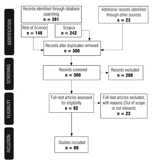
Figure 1.
Steps in the review process for the selection of articles.
3. Corrosion Monitoring Using Ground-Penetrating Radar
As mentioned earlier, the main causes of degradation are mainly the result of corrosion of reinforcement [31]. The corrosion of steel in concrete is a balanced electrochemical mechanism [32] between anodic and cathodic reactions that occur on the surface of the reinforcing steel. The anodic reaction, the oxidation of iron, occurs in an environment where the protective passive film of steel is not stable. The instability of the protective layer is related to the changes in the surrounding concrete and the main cause of these changes are processes such as chloride penetration or carbonation [32,33]. The time required for the breakdown of the passive film is called the initiation period in Tuutti’s corrosion model [34]. The further development of corrosion is called the propagation period and involves crack initiation, as a result of expansive stresses around the bar induced by rust formation. The progressive corrosion leads to spalling of the concrete and reduction of the cross-section of the reinforcement, which may compromise the load-bearing capacity of the structure [35]. Most corrosion assessment techniques are electrochemical-based [36,37]. In the field assessment of corrosion probability, the half-cell potential (HCP) and electrical resistivity (ER) are most used.
The description of the half-cell method and interpretation of the results are given in ASTM C876 [38] and RILEM recommendations [37]. The Wenner probe is commonly used to determine the electrical resistivity [39,40]. The resistivity values can be used to estimate the corrosion risk [41]. Although these methods have long been used successfully in the condition assessment of concrete structures, they have some drawbacks. The half-cell potential is a semi-destructive technique, so it requires a connection to the reinforcement. This is a limitation when a large area is to be inspected. Measuring electrical resistivity does not provide information about the reinforcement, only about the corrosive environment. Also, large areas require a lot of time for inspection. These issues can be overcome by using GPR.
Ground-penetrating radar is a non-destructive technique that emits electromagnetic waves into the material, with the main objective of locating the buried objects underneath the surface [12]. Nowadays, its scope broadens to a wide range of materials, and among others is concrete [26]. The emitted electromagnetic wave propagates through the host material, as far as it encounters an interface between different materials, whereupon it is reflected back. The predominant types of GPR antennas used for civil engineering investigations are air-coupled and ground-coupled. The second type implies contact of the antenna with the ground and has a better penetration depth. The reflected wave is recorded with the receiving antenna and the recording is called an A-scan (Figure 2, right). When a wave is transmitted, the receiver first records a direct wave propagating through the air from the transmitter to the receiver. Then, a portion of the electromagnetic wave is reflected off the surface of the material. In a ground-coupled system, these two components superimpose to form the wave, called direct coupling, Figure 2. The rest of the wave energy passes through the material until it reaches the material with different dielectric properties. The electromagnetic wave is then reflected, and the receiver records it as a reflected wave. Therefore, the attributes of the A-scan that provide information about the target are the amplitude of the reflected wave and the travel time from the transmitter to the receiver. In addition, the most common representation of the results obtained with GPR is a B-scan, the two-dimensional slice that represents the area under investigation along the line.
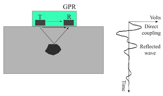
Figure 2.
Recorded signals for ground-coupled antenna.
The strength of the reflected wave depends on the properties of the host material. The properties that determine the behavior of electromagnetic waves in the material are its dielectric properties—dielectric permittivity (ε) and electrical conductivity (σ) [42]. Signal losses are mainly due to electrical conduction and dielectric relaxation [43]. Electrical conduction arises from the motion of free charges, while dielectric relaxation arises from the rotation of polar molecules. At the microscopic scale, friction occurs between particles due to these motions, resulting in energy dissipation. In summary, the propagation behavior of electromagnetic waves strongly depends on the composition of the pore solution. Changes in dielectric properties can be expected in the presence of moisture and/or chlorides in the concrete. The presence of water molecules and chlorides in pores results in an overall loss of energy and signal [43,44,45]. However, this attenuation is primarily caused by the presence of chlorides in the pore solution [46] as a result of the increased electrical conductivity of concrete. Changes in the concrete microstructure caused by carbonation can also affect the GPR response. The most noticeable ones are due to a reduction in porosity and ion exchange in the pore solution. It has been reported that carbonation causes a decrease in the dielectric permittivity, resulting in reduced attenuation [47].
3.1. Laboratory Simulated Corrosion Inspection
Corrosion assessment using ground-penetrating radar is still a novel approach, therefore only a limited number of studies have been conducted under laboratory conditions (Table 1). There are many challenges to ensure a suitable experimental setup for such a study, starting with the criteria for corrosion initiation, corrosion monitoring and corrosion probability assessment. In order to simulate natural corrosion under laboratory conditions, various techniques are often used to accelerate the process, such as impressed current technique, artificial climatic environment, accelerated migration tests, etc. [48]. The most commonly used method for corrosion acceleration is the impressed current technique, which is based on exposing the embedded reinforcement to the electric current provided by an external power supply. The current density and exposure time are controlled to achieve different degrees of corrosion [49,50]. Besides, corrosion can be enhanced by creating favorable conditions such as high temperature, high humidity and cycles of wetting–drying [51]. Even if these methods tend to simulate corrosion well, it is inevitable that the artificial conditions for corrosion to occur will differ from natural conditions. Recognition of these limitations is important to ensure adequate correlation between accelerated corrosion investigations and on-site corrosion assessments using GPR. Therefore, Table 1 summarizes the corrosion probability studies conducted to date that consider both corrosion acceleration methods and GPR signal attributes analysis. Two experimental setups were found: (a) GPR attributes acquired before and after the corrosion process, and (b) GPR attributes monitored during the corrosion acceleration process. The second setup is more significant as it ensures information about the different stages of corrosion, starting from the depassivation of the steel to the appearance of cracks.

Table 1.
Previous laboratory investigations on the influence of corrosion on the ground-penetrating radar (GPR) attributes.
One of the first studies to have acknowledged the GPR potential for corrosion detection was published in 2003 by Hubbard et al. [16]. The rebar was subjected to an accelerated corrosion process for 10 days. The results showed that corrosion causes a reduction in amplitude, which they attributed to the scattering and attenuation of waves due to the roughness at the corroded interface between concrete and rebar. This was also confirmed in Reference [52], where the amplitude of the signal was also reduced in specimens where the previously corroded bar was cast in concrete. To extend these observations, additional specimens were subjected to an accelerated corrosion process in an environmental chamber at different corrosion levels. It was found that corrosion causes a decrease in amplitude for each corrosion level. This is explained by the signal scattering in the concrete cover zone caused by the presence of cracks, corrosion products and the roughness of the corroded bar. In Reference [53], the influence of the diameter of the anode bar on the signal reflection was also observed. The increase in amplitude was associated with corrosion development but was also increased with the increase in diameter. In contrast, Reference [54] attributed lower amplitudes to the presence of corrosion products, but also indicated that the decrease could be influenced by the accumulation of chlorides in the concrete cover zone.
In Reference [55], concrete properties were simulated by oil emulsions with different dielectric permittivity, where corroded bars were immersed in the emulsions. However, in such an experimental setup, all results are based on the theories and therefore cannot faithfully represent real structures.
3.1.1. Long-Term Corrosion Monitoring
Long-term monitoring of corrosion may ensure a better understanding of its effect on GPR signal attributes. Several studies [17,18,19,20,56,57,58] have been conducted to distinguish and correlate significant attributes of corrosion development and GPR signal. The conclusions from these studies are divided into: (1) initiation phase, (2) formation of cracks and (3) spalling of concrete cover.
Initiation Phase
The application of electrical current in the accelerated corrosion process induces the faster motion of chloride ions due to the electrical potential gradient, and this mechanism is called migration [32]. As this process thrives, a decrease in GPR amplitude is reported by Lai et al. [17]. According to the authors’ assertation, the accumulation of chloride ions around the anode absorbs the energy of the electromagnetic wave, which also causes the delay of the wave.
Formation of Cracks
After the initiation phase, the researchers had noticed a steady trend of change in the signal’s attributes until the wide crack is visible on the concrete surface. This phase is characterized by the formation of corrosion products that migrate into the surrounding concrete. The increased amplitude of the reflected wave was reported in Reference [57]. The rebars were subjected to external power supply until a longitudinal crack was visible on the concrete surface. The authors claimed that the migration of corrosion products into the shallower concrete cover zone enlarges the intersection points of the signal with different interfaces—concrete, microcracks, corrosion products—and leads to the increased amplitude. This was also confirmed in References [17,56,58]. In Reference [18], the experiment was set up to exclude the effects of moisture and chlorides on the GPR signal. The specimens were stored for two months to achieve stable moisture and chloride content before accelerated corrosion. Here, the increased amplitude of the GPR signal was then attributed to the effect of corrosion only. This was also outlined in Reference [20].
Spalling
In addition to the effect of corrosion development on the GPR amplitude, the effect of crack propagation and the occurrence of wide cracks on the amplitude of the GPR signal was also noted by Lai et al. [56]. A decrease in amplitude was observed after the occurrence of a wide longitudinal crack. This was explained by the scattering of signal energy caused by additional irregularities when a wide crack propagates through the concrete cover. The extension of the experimental setup was presented in Reference [20] to obtain a better representation of the crack influence on the signal amplitude.
3.1.2. Conclusions from Laboratory Simulated Corrosion Inspection
The corrosion process can be divided into the initiation and propagation phases, with each phase having specific effects on concrete microstructures. From the long-term corrosion monitoring experiments, the influence of corrosion promotion on GPR attributes was summarized, as in Figure 3.
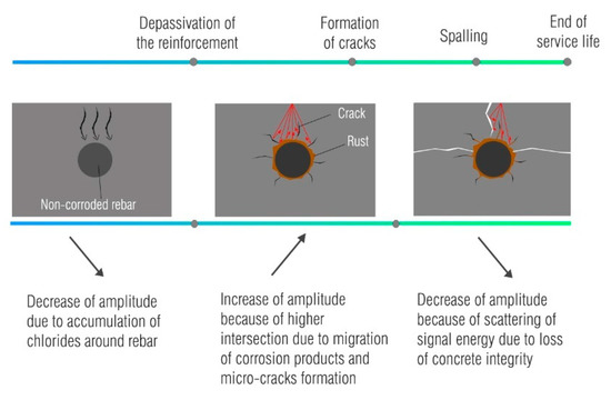
Figure 3.
Changes in the GPR signal during corrosion process.
The effects shown in Figure 3 are determined by the accelerated corrosion processes, in particular the formation of corrosion products on the surface of the reinforcing bar, their diffusion into the concrete cover and thus, crack propagation. These effects modify the amplitude in terms of different reflection coefficient and different dielectric properties of the concrete cover. The ability of corrosion products to migrate depends on the moisture content in the concrete cover since their movement is favored in the presence of moisture [59]. Similarly, the ability of their migration depends on the duration of the acceleration process. When accelerated corrosion with high current density is established in a short timeframe, it leads to increased crack width due to the sudden accumulation of corrosion products and increased pressure around the reinforcement [50,60]. Therefore, an appropriate current density should be selected to ensure the best possible simulation of natural conditions still within a reasonable timeframe [50,61].
The results of these studies also indicate that laboratory simulated corrosion studies mentioned above do not provide relevant results unless the level of corrosion is properly described. In these studies, results were recorded before and after corrosion acceleration and conflicting results were reported. Some authors reported higher amplitudes at the end of the experiments, while others reported lower amplitudes. Since these studies differ in terms of experiments setup, corrosion level and induced damage, it is possible that the observed changes in the GPR signal were recorded during different stages of the corrosion processes.
3.2. On-Site Corrosion Inspection
Most of the published research focuses on the application of GPR to the assessment of bridge decks, while other structures are represented to a lesser extent (tunnels, buildings, wharves, etc.). In terms of geographic location, most studies using GPR are conducted in the United States of America. The authors are sure that this is also a consequence of the existence of relevant standards [62].
The use of ground-penetrating radar data for condition assessment of concrete bridges dates back to the early 1980s [63]. The amplitude of the ground-penetrating radar signal during an inspection is affected by the presence of structural elements, variations in cover depth, moisture, chlorides [22,64,65] and other variables. Therefore, a simple approach to evaluating changes in the GPR signal is not practical. Coexisting influences with other phenomena, such as variations in moisture and chlorides, are unavoidable and prevent the development of methods for direct location of corroded rebar. Therefore, indirect methods are used in which the localization of corroded areas is correlated with the areas of high signal attenuation. Attenuation has been found to be strongly related to the increased conductivity around the rebar [22] caused by the accumulated chloride ions and corrosion products [25].
The inspection of concrete piers and wharves is very similar to the inspection of bridge decks where moisture and chlorides are the main causes of deterioration. The use of ground-penetrating radar has also been reported in the inspection of tunnels. It was noted that the complicated design and compound deterioration mechanisms of these structures made a simple corrosion assessment impossible. Instead, the data was used to assess the overall condition.
Quantification of attenuation can be determined by numerical analysis of the signal or by visual analysis of B-scans. These are discussed in more detail in the following sections.
3.2.1. Numerical Analysis of GPR Attributes
The ASTM standard [62] for the evaluation of concrete bridge decks using ground-penetrating radar proposes two procedures for numerical analysis using GPR data. The first procedure is based on considering the reflection amplitude from the bridge deck bottom and the bridge deck surface. The second procedure considers the reflection amplitudes from the top reinforcement layer. In most cases, the reflection amplitudes from the top reinforcement are considered for corrosion evaluation. The amplitude is derived from the A-scan.
Numerical analysis is usually performed by normalizing the amplitude, which represents the deterioration rate, and is calculated as follows [66]:
The signal amplitudes are compared to the reference signal amplitude which is usually the amplitude with the lowest degree of attenuation and represents sound concrete [66]. The GSSI [67] suggests 32,767 for 16-bit data and 2,147,483,648 for 32-bit data as the reference signal amplitude. This approach may be inconvenient when a concrete structure is in an advanced stage of deterioration and high attenuation is primarily detected. The differences between amplitudes are then smaller and the deterioration could be underestimated [68,69]. On the other hand, if the structure is in a relatively good condition, the attenuation may be misinterpreted. In this case, the attenuation could come from a different source, namely the variation of the concrete cover thickness. In such cases, it is recommended to consider the whole amplitude and not only the attenuation zones [70]. Other approaches have also been used, with Dinh et al. [25] using the average direct coupling wave as the reference amplitude. According to Pashoutani et al. [71], the use of a constant value of a reference amplitude does not take into account the contribution of concrete surface quality to the signal amplitude, even to the normalized amplitude. Therefore, a normalization procedure was proposed in which each signal amplitude is normalized to its own direct coupling amplitude. In order to eliminate the influence of the cover depth variation on the signal amplitude, Barnes et al. [21] demonstrated an amplitude correction method. It was shown that subtracting the depth-dependent amplitude loss gives a better correlation of ground-penetrating radar amplitude maps with ground truth results than maps without correction. The method is based on determining the linear-dependent function of signal loss from the two-way travel time (TWTT) for the 90th percentile value of normalized amplitude. The 90th percentile value of the normalized amplitude is supposed to represent the sound concrete where the attenuation is mainly caused by the propagation of the signal through the dielectric material, i.e., the dielectric loss [25]. After correction of the amplitude, the attenuation should represent the signal loss due to chloride and moisture, i.e., the conductive loss. The method was improved after it was found that the conductive loss was also depth-dependent, so that an additional correction was necessary [25]. Two automated methods for depth correction have also been proposed [72]. In these studies, the correction was performed at the two-way travel time level. A more accurate correction could be performed if the linear function is determined using the real reinforcement depth instead of the two-way travel time [71]. This procedure requires the determination of the real velocities of the signal.
Obviously, it is of interest to establish a threshold for attenuation that is suitable for identifying the area of deterioration. However, a universally applicable threshold has not been established. It is usually based on the experience of the analyst and is related to a specific case [21]. There have been several attempts to relate the attenuation, mostly in comparison with thresholds of other methods. In References [73,74,75,76], ground-penetrating radar data were correlated with half-cell potential data, with the aim of determining the threshold value of attenuation. In Reference [75], the ROC (Receiver Operating Characteristic) curve was used, and in Reference [76], the author used statistical parameters to obtain the threshold value. In the second paper, the relationship between the percentage of corroded area, based on the results obtained with the half-cell potential at several bridges, and the product of the mean and skewness of the amplitude of the ground-penetrating radar, was established. The relationship can be used to predict the corroded area based on the analysis of the statistical parameters of the amplitudes. In some studies [77,78], the k-means clustering method was used to determine thresholds values.
Numerical analysis is generally used to obtain the deterioration map, which in most cases is the spatial distribution of normalized amplitudes. The main steps of the numerical approach in the condition assessment of concrete bridge decks are shown in Figure 4. The ability of the numerical approach to provide autonomous assessment of concrete structures using GPR is one of the reasons for its predominant use, while the algorithms for automatic reinforcement selection can be found in References [79,80].
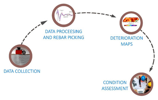
Figure 4.
Numerical approach in condition assessment of concrete bridge decks.
The results obtained by periodical inspections can be collected in databases, so that the correlation of successive data allows continuous monitoring of the progress of deterioration. Dinh et al. [65] also proposed a method based on comparing the complete waveform (amplitudes and shapes of the electromagnetic wave) at a point with baseline data. The advantage of this method is that it excludes non-corrosion attenuation causes. However, baseline data is required for proper detection of deterioration, which is often not available. The method was improved in Reference [81] and the waveform was compared with the simulated waveform. The simulated waveform has the original direct wave, but it has no reflected wave, so it simulates full attenuation. The higher similarity with the simulated wave correlates with a higher degree of deterioration. Hong et al. [82] proposed a method to monitor the corrosion process by comparing different GPR data using the image registration technique.
Despite the deterioration maps, the statistical distribution of amplitudes had shown the relationship with the condition of the structure. In Reference [83], where several bridges with different environmental conditions were observed, it was found that after correcting the amplitude depth, the distribution of the amplitude of the sound deck was symmetrical with high kurtosis. In contrast, severely damaged concrete exhibited higher dispersion of amplitude distribution with lower value of kurtosis. This statistical dependence has been previously confirmed [74]. An automated crack tracking method based on the analysis of the processed amplitude of the ground-penetrating radar was presented in Reference [84]. The model considers the amplitude compared with the threshold value. The final result of the model is a three-dimensional (3D) visualization of the cracks, which provides the possibility to evaluate their geometry. However, the reliability of the model depends on the threshold value, which is difficult to determine accurately.
3.2.2. Visual-Based or Combined Analysis of GPR Attributes
In addition to the numerical approach, a visual or combined visual and numerical approach has been supported by a number of authors [22,77,85]. The visual approach implies the visual analysis of B-scans. This method is highly dependent on the expertise of the analyst, especially in the case of severely damaged structures [86], so the final conclusion is prone to error. As noted by some authors [22], numerical analysis of amplitudes misinterprets most anomalies that alter the signal and are not causes of deterioration (surface anomalies, reinforcement spacing, reinforcement depth, structural variations). Due to of these drawbacks, a method is proposed in which an analyst reviews the ground-penetrating radar profiles (B-scans), considers the reflections of the reinforcement and concrete surfaces and marks the boundaries of deteriorated areas. The profiles are processed, and the final output is the corrosion map. The detailed procedure is described in Reference [87]. This method was improved to overcome the subjective opinion of analysts in visual-based interpretation [85]. A set of if/then rules was created to locate anomalies that alter the signal but do not indicate deterioration. Dinh et al. [77] used visual analysis of ground-penetrating radar profiles as a tool to determine the number of condition categories as input to the k-means clustering method. It is a combined method: after determining the number of condition categories, the amplitudes of the signal are grouped and thresholds between the groups are determined. The corrosion map obtained in this way was used for the deterioration modelling of concrete bridge decks presented in Reference [88]. Dawood et al. [89] presented an improved visual-based analysis of ground-penetrating radar data for the detection of air and water voids in tunnels. Moreover, an evaluation flowchart based on inspection of pier structure considering B-scans and GPR signal energy was proposed in Reference [90].
3.2.3. Condition Assessment by Combination of Multiple NDT
Ground-penetrating radar has a number of advantages over other non-destructive techniques (NDT), and it is not surprising that it has shown much interest in replacing other techniques. It is completely non-destructive, and it is rational to give it precedence over other techniques that make surveying slow and less efficient. In the next sections, a brief overview is shown on current research results obtained by comparing GPR data with other test methods, such as electrical resistivity (ER), half-cell potential (HCP), chain drag (CD), hammer sounding (HS), infrared thermography (IRT), acoustic emission (AE) and impact-echo (IE). These studies are summarized in Table 2.
Table 2.
Review of studies that combined GPR with other techniques.
Electrical resistivity and half-cell potential are fundamental tools for determining the probability of corrosion in the condition assessment of concrete structures. A good correlation has been found in the analysis of electrical resistivity and GPR data [81,91,92,93]. However, such behavior is to be expected as both techniques are affected by the conductivity of the concrete [91].
The comparison between HCP and GPR data can be found in References [21,24,69,73,74,81,92,93]. All observations were obtained by superimposing the signal attenuation and potential maps. In most studies, a good correlation was found since the attenuation is indicative of a corrosive environment and coincides with the areas of extremely negative half-cell potentials [92]. However, when the degree of deterioration is low, the ground-penetrating radar could overestimate corroded areas [69].
Other techniques can also serve for condition assessment and correctly predict potential deterioration due to corrosion propagation. These techniques include chain drag (CD), hammer sounding (HS), infrared thermography (IRT), acoustic emission (AE) and impact-echo (IE). Compared to the chain-drag method, the ground-penetrating radar is effective while the deterioration level ranged between 10% and 50% [69]. However, the divergence between the result of the ground-penetrating radar and the acoustic scanning system was observed in Reference [94], where the authors investigated the suitability of these techniques for delamination detection. The area of high attenuation was larger than the delaminated area detected by the acoustic system because the ground-penetrating radar generally detects the deterioration earlier than the acoustic system. The GPR can detect deterioration before delamination occurs. Also, the comparative feasibility study on delamination detection using ground-penetrating radar (GPR) and infrared thermography (IRT) based on ROC (Receiver Operating Characteristic) analysis showed that IRT is more reliable than GPR in detecting delamination [95]. However, the contribution of IRT is limited to a shallow cover depth, while GPR can provide a deeper insight. Also, the usefulness of GPR in predicting repair quantities was presented in Reference [96], where the results of ground-penetrating radar matched the depth of removal measured by LiDAR (Light Detection and Ranging) method after hydro-demolition.
In a very detailed study, Omar et al. [109] presented the weaknesses and advantages of the most commonly used methods for condition assessment of concrete bridges. The conclusion was that none of the commonly used techniques are able to detect active corrosion, delamination and vertical cracking simultaneously, so that the most reliable condition assessment lies in a combination of multiple techniques. Such an approach ensures accurate condition assessment as deterioration can be detected from its onset to an advanced stage [23].
The simultaneously used non-destructive techniques usually consider methods such as ground-penetrating radar, electrical resistivity, half-cell potential, ultrasonic surface waves, impact-echo, etc. In References [14,100,110], an example of integration of different non-destructive testing methods in robotic systems, RABIT (Robotics Assisted Bridge Inspection Tool), was presented, which ensures real-time visualization of the concrete deck condition. Here, the evaluation is supported by a Jensen–Shannon probability method that focuses on the determination of the condition index [108]. Additional support in the interpretation of GPR data for delamination detection can be provided by infrared thermography (IRT) [99,103,104,107]. Solla et al. [106] demonstrated the technique to inspect a military base in an advanced stage of corrosion with visible signs of damage such as cracking and spalling. The results obtained with GPR were combined with the IRT technique. The corrosion assessment was based on the observation of GPR signal attenuation, changes in signal velocity and amplitude polarity. Overall, high signal attenuation was declared to indicate the presence of mineral salts and moisture, while reverse reflection polarity could be a sign of voids. The same parameters have been used in the assessment of wastewater plants [111], although the corrosion process is different in this case.
Deterioration modelling was part of the study in Reference [102], in which deterioration curves were developed based on the condition assessment of 10 bridges. Similar assessments were carried out by Alani et al. [101], where finite element models were constructed based on inputs from ground-penetrating radar and the deflection and vibration sensor system. In Reference [105], a data fusion model for bridge deck evaluation was developed based on the combination of the results from the ground-penetrating radar, half-cell potential method, electrical resistivity method and impact-echo method. In Reference [112], the ground-penetrating radar data combined with the capacitive technique and the impact-echo method were correlated with durability indicators for the overall assessment of the wharf.
3.2.4. Conclusions from the On-Site Corrosion Inspection
The previous section has shown that corrosion assessment in on-site corrosion testing is mostly based on the assessment of the attenuated areas identified by signal amplitude analysis. Most of the studies are carried out on the bridge decks. In terms of comparison with other NDT, GPR has been compared with various techniques used for the service life condition assessment of the structures, Figure 5.
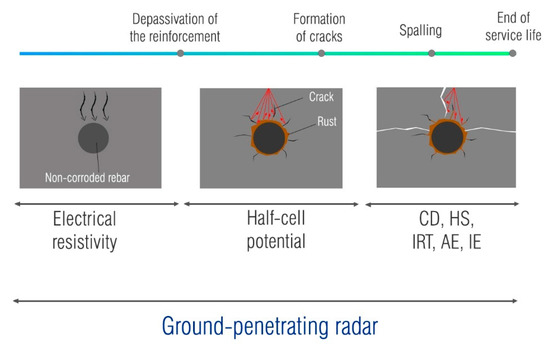
Figure 5.
Multiple NDT used for the condition assessment.
The high correlation between the electrical resistivity and the attenuation maps obtained with ground-penetrating radar is to be expected, as the signal depends on the material properties, so the conductive medium generated by moisture and chlorides changes its properties. In general, the GPR has shown good agreement with the HCP. However, there are certain situations where the GPR does not agree very well with the HCP. In cases where moisture and chlorides provide a favorable environment for corrosion, but their concentration is not sufficient to start corrosion, the GPR and HCP maps may differ. The applicability of ground-penetrating radar in detecting delamination is also uncertain [113]. In many cases, it does not detect delamination directly, and the assessment is based on the localization of deteriorated areas [114]. Moreover, the visual signs of delamination are not always visible on B-scans [87]. If the delamination is too thin to be detected by the antenna, it will not show any detectable change on the scan.
In summary, additional information, such as the age of the structure or the environmental conditions, may be helpful in analyzing GPR results. Moreover, this additional information can be obtained with other NDT, so a suitable combination of NDT can be a very powerful tool for the condition assessment of concrete structures.
4. Conclusions
This paper investigated the evaluation of corrosion probability in concrete using ground-penetrating radar. The study analyzed laboratory and on-site investigations and the results were related to the evolution of the corrosion process. Advantages and recommendations for future research are presented below.
GPR is a completely non-destructive method, which gives it an advantage over other techniques for corrosion assessment of reinforced concrete. Its ability to examine large areas in a short time, together with providing information on the depth and spacing of reinforcement, makes it a multifunctional NDT. The literature review identified certain challenges in the use of GPR for corrosion assessment, one of the main being the understanding of the influence of concrete conditions on GPR parameters. In fact, in most laboratory studies, moisture and chloride content were controlled after depassivation of the reinforcement. On-site in real conditions, variations of moisture and chloride content are inevitable, which makes the detection of corroded areas based only on the observation of amplitude potentially ambiguous. Since opposing data have been reported in the literature, further laboratory studies are needed to show the influence of the change in dielectric properties of the concrete cover on the GPR amplitude and the change in reflection coefficient due to the formation of corrosion products and their migration. Since an absolute comparison of studies is difficult due to the variance in experimental design and the degree of damage induced by the accelerated corrosion process, further studies should correlate the degree of damage with the change in GPR amplitude. Obtaining concluding results from the proposed research topics could enable the use of GPR as a stand-alone tool for detecting corroded areas, moving from its use for the detection of corrosive environment towards detection of corrosion itself.
In conclusion, as the knowledge of the effect of corrosion on the GPR signal increases, GPR will be a very valuable tool for condition assessment of reinforced concrete structures. This method will certainly be improved, leading to an upgrade of the construction management system and making the assessment more reliable with reduced maintenance costs.
Author Contributions
Conceptualization, K.T., A.B. and M.S.; methodology, K.T. and A.B.; investigation, K.T. and A.B.; data curation, K.T.; writing—original draft preparation, K.T.; writing—review and editing, A.B. and M.S.; visualization, K.T.; supervision, A.B.; project administration, M.S.; funding acquisition, M.S. All authors have read and agreed to the published version of the manuscript.
Funding
This research was funded by the European Union through the European Regional Development Fund’s Competitiveness and Cohesion Operational Program, grant number KK.01.1.1.04.0041, project “Autonomous System for Assessment and Prediction of infrastructure integrity (ASAP)”.
Institutional Review Board Statement
Not applicable.
Informed Consent Statement
Not applicable.
Data Availability Statement
Not applicable.
Conflicts of Interest
Authors declare no conflict of interest. The funders had no role in the design of the study; in the collection, analyses, or interpretation of data; in the writing of the manuscript, or in the decision to publish the results.
References
- Croatian, P. Building Act, NN 153/2013; Official Gazette: Zagreb, Croatia, 2017.
- Mehta, B.P.K.; Burrows, R.W. Building Durable Structures in the 21st Century. Concr. Int. 2001, 23, 57–63. [Google Scholar]
- Bossio, A.; Monetta, T.; Bellucci, F.; Lignola, G.P.; Prota, A. Modeling of concrete cracking due to corrosion process of reinforcement bars. Cem. Concr. Res. 2015, 71, 78–92. [Google Scholar] [CrossRef]
- Yan, L.; Chouw, N. Behavior and analytical modeling of natural flax fibre-reinforced polymer tube confined plain concrete and coir fibre-reinforced concrete. J. Compos. Mater. 2013, 47, 2133–2148. [Google Scholar] [CrossRef]
- Vecchio, F.J.; Bucci, F. Analysis of Repaired Reinforced Concrete Structures. J. Struct. Eng. 1999, 125, 644–652. [Google Scholar] [CrossRef]
- Navarro, I.J.; Yepes, V.; Martí, J.V.; González-Vidosa, F. Life cycle impact assessment of corrosion preventive designs applied to prestressed concrete bridge decks. J. Clean. Prod. 2018, 196, 698–713. [Google Scholar] [CrossRef]
- Cao, Y.; Dong, S.; Zheng, D.; Wang, J.; Zhang, X.; Du, R.; Song, G.; Lin, C. Multifunctional inhibition based on layered double hydroxides to comprehensively control corrosion of carbon steel in concrete. Corros. Sci. 2017, 126, 166–179. [Google Scholar] [CrossRef]
- Luo, H.; Su, H.; Dong, C.; Li, X. Passivation and electrochemical behavior of 316L stainless steel in chlorinated simulated concrete pore solution. Appl. Surf. Sci. 2017, 400, 38–48. [Google Scholar] [CrossRef]
- Pan, X.; Shi, Z.; Shi, C.; Ling, T.C.; Li, N. A review on concrete surface treatment Part I: Types and mechanisms. Constr. Build. Mater. 2017, 132, 578–590. [Google Scholar] [CrossRef]
- Ohtsu, M. Introduction. In Innovative AE and NDT Techniques for On-Site Measurement of Concrete and Masonry Structures; Ohtsu, M., Ed.; Springer: Dordrecht, Germany, 2016; pp. 1–4. [Google Scholar]
- Núñez-Nieto, X.; Solla, M.; Lorenzo, H. Applications of GPR for Humanitarian Assistance and Security. In Civil Engineering Applications of Ground Penetrating Radar; Pajewski, L., Benedetto, A., Eds.; Springer: New Delhi, India, 2015; pp. 301–326. [Google Scholar]
- Annan, A.P. Electromagnetic Principles of Ground Penetrating Radar. In Ground Penetrating Radar: Theory and Applications; Jol, M.H., Ed.; Elsevier B.V.: Amsterdam, The Netherlands, 2009; pp. 1–40. [Google Scholar]
- Daniels, D.J. Introduction. In Ground Penetrating Radar, 2nd ed.; The Institution of Electrical Engineers: London, UK, 2004; pp. 1–11. [Google Scholar]
- Gucunski, N.; Basily, B.; Kim, J.; Duong, T.; Maher, A.; Dinh, K.; Azari, H.; Ghasemi, H. Assessing Condition of Concrete Bridge Decks by Robotic Platform RABIT for Development of Deterioration and Predictive Models. In Proceedings of the 8th International Conference on Bridge Maintenance, Safety and Management (IABMAS), Foz do Iguacu, Brazil, 26–30 June 2016. [Google Scholar]
- Reichling, K.; Raupach, M.; Wiggenhauser, H.; Stoppel, M.; Dobmann, G.; Kurz, J. BETOSCAN—Robot controlled non-destructive diagnosis of reinforced concrete decks. In Proceedings of the NDTCE’09, Non Destructive Testing in Civil Engineering, Nantes, France, 30 June–3 July 2009. [Google Scholar]
- Hubbard, S.S.; Zhang, J.; Monteiro, P.J.M.; Peterson, J.E.; Rubin, Y. Experimental Detection of Reinforcing Bar Corrosion Using Nondestructive Geophysical Techniques. ACI Mater. J. 2003, 100, 501–510. [Google Scholar] [CrossRef]
- Lai, W.W.L.; Kind, T.; Stoppel, M.; Wiggenhauser, H. Measurement of Accelerated Steel Corrosion in Concrete Using Ground-Penetrating Radar and a Modified Half-Cell Potential Method. J. Infrastruct. Syst. 2013, 19, 205–220. [Google Scholar] [CrossRef]
- Hong, S.; Lai, W.W.L.; Wilsch, G.; Helmerich, R.; Helmerich, R.; Günther, T.; Wiggenhauser, H. Periodic mapping of reinforcement corrosion in intrusive chloride contaminated concrete with GPR. Constr. Build. Mater. 2014, 66, 671–684. [Google Scholar] [CrossRef]
- Hong, S.; Lai, W.W.L.; Helmerich, R. Experimental monitoring of chloride-induced reinforcement corrosion and chloride contamination in concrete with ground-penetrating radar. Struct. Infrastruct. Eng. 2015, 11, 15–26. [Google Scholar] [CrossRef]
- Wong, P.T.W.; Lai, W.W.L.; Sham, J.F.C.; Poon, C. Hybrid non-destructive evaluation methods for characterizing chloride-induced corrosion in concrete. NDT E Int. 2019, 107. [Google Scholar] [CrossRef]
- Barnes, C.L.; Trottier, J.F.; Forgeron, D. Improved concrete bridge deck evaluation using GPR by accounting for signal depth-amplitude effects. NDT E Int. 2008, 41, 427–433. [Google Scholar] [CrossRef]
- Tarussov, A.; Vandry, M.; De La Haza, A. Condition assessment of concrete structures using a new analysis method: Ground-penetrating radar computer-assisted visual interpretation. Constr. Build. Mater. 2013, 38, 1246–1254. [Google Scholar] [CrossRef]
- Gucunski, N.; Romero, F.; Kruschwitz, S.; Feldmann, R.; Abu-Hawash, A.; Dunn, M. Multiple complementary nondestructive evaluation technologies for condition assessment of concrete bridge decks. Transp. Res. Rec. 2010, 34–44. [Google Scholar] [CrossRef]
- Barnes, C.L.; Trottier, J.F. Ground-Penetrating Radar for Network-Level Concrete Deck Repair Management. J. Transp. Eng. 2000, 126, 257–262. [Google Scholar] [CrossRef]
- Dinh, K.; Gucunski, N.; Kim, J.; Duong, T.H. Understanding depth-amplitude effects in assessment of GPR data from concrete bridge decks. NDT E Int. 2016, 83, 48–58. [Google Scholar] [CrossRef]
- Lai, W.W.L.; Dérobert, X.; Annan, A.P. A review of Ground Penetrating Radar application in civil engineering: A 30-year journey from Locating and Testing to Imaging and Diagnosis. NDT E Int. 2018, 96, 58–78. [Google Scholar] [CrossRef]
- Tosti, F.; Ferrante, C. Using Ground Penetrating Radar Methods to Investigate Reinforced Concrete Structures. Surv. Geophys. 2020, 41, 485–530. [Google Scholar] [CrossRef]
- Abu Dabous, S.; Feroz, S. Condition monitoring of bridges with non-contact testing technologies. Autom. Constr. 2020, 116. [Google Scholar] [CrossRef]
- Clarivate Analytics Web of Science. Available online: www.webofknowledge.com (accessed on 30 October 2020).
- Science Direct Scopus. Available online: https://www.scopus.com (accessed on 30 October 2020).
- Beushausen, H.; Torrent, R.; Alexander, M.G. Performance-based approaches for concrete durability: State of the art and future research needs. Cem. Concr. Res. 2019, 119, 11–20. [Google Scholar] [CrossRef]
- Bertolini, L.; Elsener, B.; Pedeferri, P.; Redaelli, E.; Polder, R. Corrosion of Steel in Concrete: Prevention, Diagnosis, Repair, 2nd ed.; Wiley-VCH Verlag GmbH & Co.: Weinheim, Germany, 2013. [Google Scholar]
- Broomfield, J.P. Corrosion of Steel in Concrete: Understanding, Investigation and Repair, 2nd ed.; Taylor and Francis: London, UK, 2003. [Google Scholar]
- Tuutti, K. Corrosion of Steel in Concrete; Swedish Cement and Concrete Research Institute: Stockholm, Sweden, 1982. [Google Scholar]
- Alexander, M.; Beushausen, H. Durability, service life prediction, and modelling for reinforced concrete structures—Review and critique. Cem. Concr. Res. 2019, 122, 17–29. [Google Scholar] [CrossRef]
- Andrade, C.; Alonso, C.; Gulikers, J.; Polder, R.; Cigna, R.; Vennesland, O.; Salta, M.; Raharinaivo, A.; Elsener, B. Test methods for on-site corrosion rate measurement of steel reinforcement in concrete by means of the polarization resistance method. Mater. Struct. 2004, 37, 623–643. [Google Scholar] [CrossRef]
- Elsener, B.; Andrade, C.; Gulikers, J.; Polder, R.; Raupach, M. Half-cell potential measurements—Potential mapping on reinforced concrete structures. Mater. Struct. 2003, 36, 461–471. [Google Scholar] [CrossRef]
- ASTM C876-91. Standard Test Method for Half-Cell Potentials of Uncoated Reinforcing Steel in Concrete; ASTM International: West Conshohocken, PA, USA, 1999. [Google Scholar]
- Hornbostel, K.; Larsen, C.K.; Geiker, M.R. Relationship between concrete resistivity and corrosion rate—A literature review. Cem. Concr. Compos. 2013, 39, 60–72. [Google Scholar] [CrossRef]
- Song, H.W.; Saraswathy, V. Corrosion monitoring of reinforced concrete structures—A review. Int. J. Electrochem. Sci. 2007, 2, 1–28. [Google Scholar] [CrossRef]
- Polder, R.; Andrade, C.; Elsener, B.; Vennesland, O.; Gulikers, J.; Weidert, R.; Raupach, M. Test methods for on site measurement of resistivity of concrete. Mater. Struct. 2000, 33, 603–611. [Google Scholar] [CrossRef]
- Cassidy, N.J. Electrical and Magnetic Properties of Rocks, Soils and Fluids. In Ground Penetrating Radar: Theory and Applications; Jol, H.M., Ed.; Elsevier B.V.: Amsterdam, The Netherlands, 2009; pp. 41–72. [Google Scholar]
- Laurens, S.; Balayssac, J.P.; Rhazi, J.; Arliguie, G. Influence of concrete relative humidity on the amplitude of ground-penetrating radar (GPR) signal. Mater. Struct. 2002, 35, 198–203. [Google Scholar] [CrossRef]
- Sbartaï, Z.M.; Laurens, S.; Balayssac, J.; Arliguie, G.; Ballivy, G. Ability of the direct wave of radar ground-coupled antenna for NDT of concrete structures. NDT E Int. 2006, 39, 400–407. [Google Scholar] [CrossRef]
- Hugenschmidt, J.; Loser, R. Detection of chlorides and moisture in concrete structures with ground penetrating radar. Mater. Struct. 2008, 41, 785–792. [Google Scholar] [CrossRef]
- Senin, S.F.; Hamid, R. Ground penetrating radar wave attenuation models for estimation of moisture and chloride content in concrete slab. Constr. Build. Mater. 2016, 106, 659–669. [Google Scholar] [CrossRef]
- Dérobert, X.; Villain, G.; Balayssac, J.P. Influence of concrete carbonation on electromagnetic permittivity measured by GPR and capacitive techniques. J. Environ. Eng. Geophys. 2018, 23, 443–456. [Google Scholar] [CrossRef]
- Ahmad, S. Techniques for inducing accelerated corrosion of steel in concrete. Arab. J. Sci. Eng. 2009, 34, 95–104. [Google Scholar]
- Malumbela, G.; Moyo, P.; Alexander, M. A step towards standardising accelerated corrosion tests on laboratory reinforced concrete specimens. J. South African Inst. Civ. Eng. 2012, 54, 78–85. [Google Scholar]
- El Maaddawy, T.A.; Soudki, K.A. Effectiveness of Impressed Current Technique to Simulate Corrosion of Steel Reinforcement in Concrete. J. Mater. Civ. Eng. 2003, 15, 41–47. [Google Scholar] [CrossRef]
- Yuan, Y.; Ji, Y.; Shah, S.P. Comparison of Two Accelerated Corrosion Techniques for Concrete Structures. ACI Struct. J. 2007, 104, 344–347. [Google Scholar]
- Sossa, V.; Pérez-Gracia, V.; González-Drigo, R.; Rasol, M.A. Lab non destructive test to analyze the effect of corrosion on ground penetrating radar scans. Remote Sens. 2019, 11, 2814. [Google Scholar] [CrossRef]
- Raju, R.K.; Hasan, M.I.; Yazdani, N. Quantitative relationship involving reinforcing bar corrosion and ground-penetrating radar amplitude. ACI Mater. J. 2018, 115, 449–457. [Google Scholar] [CrossRef]
- Zaki, A.; Johari, M.A.; Hussin, W.M.A.W.; Jusman, Y. Experimental Assessment of Rebar Corrosion in Concrete Slab Using Ground Penetrating Radar (GPR). Int. J. Corros. 2018, 2018. [Google Scholar] [CrossRef]
- Hasan, M.I.; Yazdani, N. An experimental study for quantitative estimation of rebar corrosion in concrete using ground penetrating radar. J. Eng. 2016, 2016. [Google Scholar] [CrossRef]
- Lai, W.W.L.; Kind, T.; Wiggenhauser, H. Detection of accelerated reinforcement corrosion in concrete by ground penetrating radar. In Proceedings of the XIII Internartional Conference on Ground Penetrating Radar, Lecce, Italy, 21–25 June 2010. [Google Scholar]
- Zhan, B.J.; Lai, W.W.L.; Kou, S.C.; Poon, C.S.; Tsang, W.F. Correlation between accelerated steel corrosion in concrete and ground penetrating radar parameters. In Proceedings of the International RILEM Conference on Advances in Construction Materials Through Science and Engineering, Hong Kong, China, 5–7 September 2011. [Google Scholar]
- Lai, W.W.L.; Kind, T.; Wiggenhauser, H. Using ground penetrating radar and time-frequency analysis to characterize construction materials. NDT E Int. 2011, 44, 111–120. [Google Scholar] [CrossRef]
- Hong, S. GPR-Based Periodic Monitoring of Reinforcement Corrosion in Chloride- Contaminated Concrete. Ph.D. Thesis, TU Berlin, Berlin, Germany, 2015. [Google Scholar]
- Said, M.E.; Hussein, A.A. Induced Corrosion Techniques for Two-Way Slabs. J. Perform. Constr. Facil. 2019, 33. [Google Scholar] [CrossRef]
- Altoubat, S.; Maalej, M.; Shaikh, F.U.A. Laboratory Simulation of Corrosion Damage in Reinforced Concrete. Int. J. Concr. Struct. Mater. 2016, 10, 383–391. [Google Scholar] [CrossRef]
- ASTM D6087-08. Standard Test Method for Evaluating Asphalt-Covered Concrete Bridge Decks Using Ground Penetrating Radar; ASTM International: West Conshohocken, PA, USA, 2008. [Google Scholar]
- Saarenketo, T. NDT Transportation. In Ground Penetrating Radar: Theory and Applications; Jol, H.M., Ed.; Elsevier B.V.: Amsterdam, The Netherlands, 2009; pp. 395–444. [Google Scholar]
- Belli, K.M.; Birken, R.A.; Vilbig, R.A.; Wadia-Fascetti, S.J. Simulated GPR investigation of deterioration in reinforced concrete bridge decks. In Proceedings of the Symposium on the Application of Geophysics to Engineering and Environmental Problems 2013, Denver, CO, USA, 17–21 March 2013. [Google Scholar]
- Dinh, K.; Zayed, T.; Romero, F.; Tarussov, A. Method for analyzing time-series GPR data of concrete bridge decks. J. Bridg. Eng. 2015, 20. [Google Scholar] [CrossRef]
- Diamanti, N.; Annan, A.P.; Redman, J.D. Concrete Bridge Deck Deterioration Assessment Using Ground Penetrating Radar (GPR). J. Environ. Eng. Geophys. 2017, 22. [Google Scholar] [CrossRef]
- GSSI. RADAN 7 Manual; Geophysical Survey Systems, Inc.: Nashua, NH, USA, 2015. [Google Scholar]
- Barnes, C.L.; Trottier, J.F. Phenomena and conditions in bridge decks that confound ground-penetrating radar data analysis. Transp. Res. Rec. 2002, 57–61. [Google Scholar] [CrossRef]
- Barnes, C.L.; Trottier, J.F. Effectiveness of Ground Penetrating Radar in Predicting Deck Repair Quantities. J. Infrastruct. Syst. 2004, 10, 69–76. [Google Scholar] [CrossRef]
- Parrillo, B.; Roberts, R. Bridge deck condition assessment using ground penetrating radar. In Proceedings of the 9th European Conference on NDT (ECNDT), Berlin, Germany, 25–29 September 2006. [Google Scholar]
- Pashoutani, S.; Zhu, J. Ground Penetrating Radar Data Processing for Concrete Bridge Deck Evaluation. J. Bridg. Eng. 2020, 25. [Google Scholar] [CrossRef]
- Romero, F.A.; Barnes, C.L.; Azari, H.; Nazarian, S.; Rascoe, C.D. Validation of Benefits of Automated Depth Correction Method Improving Accuracy of Ground-Penetrating Radar Deck Deterioration Maps. Transp. Res. Rec. 2015, 100–109. [Google Scholar] [CrossRef]
- Rhazi, J.; Dous, O.; Laurens, S. A New Application of the GPR Technique To Reinforced Concrete. In Proceedings of the 4th Middle NDT Conference and Exhibition, Manama, Bahrain, 2–5 December 2007. [Google Scholar]
- Maser, K.; Martino, N.; Doughty, J.; Birken, R. Understanding and detecting bridge deck deterioration with ground-penetrating radar. Transp. Res. Rec. 2012, 116–123. [Google Scholar] [CrossRef]
- Martino, N.; Maser, K.; Birken, R.; Wang, M. Determining ground penetrating radar amplitude thresholds for the corrosion state of reinforced concrete bridge decks. J. Environ. Eng. Geophys. 2014, 19, 175–181. [Google Scholar] [CrossRef]
- Martino, N.; Maser, K.; Birken, R.; Wang, M. Quantifying Bridge Deck Corrosion Using Ground Penetrating Radar. Res. Nondestruct. Eval. 2016, 27, 112–124. [Google Scholar] [CrossRef]
- Dinh, K.; Zayed, T.; Moufti, S.; Shami, A.; Jabri, A.; Abouhamad, M.; Dawood, T. Clustering-Based Threshold Model for Condition Assessment of Concrete Bridge Decks with Ground-Penetrating Radar. Transp. Res. Rec. 2015, 81–89. [Google Scholar] [CrossRef]
- Alsharqawi, M.; Zayed, T.; Shami, A. Ground penetrating radar-based deterioration assessment of RC bridge decks. Constr. Innov. 2020, 20, 1–17. [Google Scholar] [CrossRef]
- Dinh, K.; Gucunski, N.; Duong, T.H. An algorithm for automatic localization and detection of rebars from GPR data of concrete bridge decks. Autom. Constr. 2018, 89, 292–298. [Google Scholar] [CrossRef]
- Ma, X.; Liu, H.; Wang, M.L.; Birken, R. Automatic detection of steel rebar in bridge decks from ground penetrating radar data. J. Appl. Geophys. 2018, 158, 93–102. [Google Scholar] [CrossRef]
- Dinh, K.; Gucunski, N.; Kim, J.; Duong, T.H. Method for attenuation assessment of GPR data from concrete bridge decks. NDT E Int. 2017, 92, 50–58. [Google Scholar] [CrossRef]
- Hong, S.; Wiggenhauser, H.; Helmerich, R.; Dong, B.; Dong, P.; Xing, F. Long-term monitoring of reinforcement corrosion in concrete using ground penetrating radar. Corros. Sci. 2017, 114, 123–132. [Google Scholar] [CrossRef]
- Rhee, J.Y.; Shim, J.; Kee, S.H.; Lee, S.Y. Different Characteristics of Radar Signal Attenuation Depending on Concrete Condition of Bare Bridge Deck. KSCE J. Civ. Eng. 2020, 24, 2049–2062. [Google Scholar] [CrossRef]
- Benedetto, A. A three dimensional approach for tracking cracks in bridges using GPR. J. Appl. Geophys. 2013, 97, 37–44. [Google Scholar] [CrossRef]
- Abouhamad, M.; Dawood, T.; Jabri, A.; Alsharqawi, M.; Zayed, T. Corrosiveness mapping of bridge decks using image-based analysis of GPR data. Autom. Constr. 2017, 80, 104–117. [Google Scholar] [CrossRef]
- Martino, N.; Maser, K. Comparison of air-coupled GPR data analysis results determined by multiple analysts. In Proceedings of the SPIE Conference on Health Monitoring of Structural and Biological Systems, Las Vegas, NV, USA, 21–24 March 2016. [Google Scholar]
- Dinh, K.; Zayed, T.; Tarussov, A. GPR image analysis for corrosion mapping in concrete slabs. In Proceedings of the Canadian Society of Civil Engineering 2013 Conference, Montreal, QC, Canada, 29 May–1 June 2013. [Google Scholar]
- Alsharqawi, M.; Zayed, T.; Abu Dabous, S. Integrated condition rating and forecasting method for bridge decks using Visual Inspection and Ground Penetrating Radar. Autom. Constr. 2018, 89, 135–145. [Google Scholar] [CrossRef]
- Dawood, T.; Zhu, Z.; Zayed, T. Deterioration mapping in subway infrastructure using sensory data of GPR. Tunneling Undergr. Sp. Technol. 2020, 103. [Google Scholar] [CrossRef]
- Sham, J.F.C.; Wallace, W.L.L. Diagnosis of reinforced concrete structures by Ground Penetrating Radar survey-case study. In Proceedings of the 9th International Workshop on Advanced Ground Penetrating Radar (IWAGPR), Edinburgh, UK, 28–30 June 2017. [Google Scholar]
- Gucunski, N.; Parvardeh, H.; Romero, F.; Pailes, B.M. Deterioration progression monitoring in concrete bridge decks using periodical NDE surveys. In Proceedings of the Second Conference on Smart Monitoring, Assessment and Rehabilitation of Civil Structures (SMAR 2013), Istanbul, Turkey, 9–11 September 2013. [Google Scholar]
- Dinh, K.; Gucunski, N.; Zayed, T. Automated visualization of concrete bridge deck condition from GPR data. NDT E Int. 2019, 102, 120–128. [Google Scholar] [CrossRef]
- Pailes, B.M.; Gucunski, N. Understanding Multi-modal Non-destructive Testing Data Through the Evaluation of Twelve Deteriorating Reinforced Concrete Bridge Decks. J. Nondestruct. Eval. 2015, 34, 1–14. [Google Scholar] [CrossRef]
- Sun, H.; Pashoutani, S.; Zhu, J. Nondestructive evaluation of concrete bridge decks with automated acoustic scanning system and ground penetrating radar. Sensors 2018, 18, 1955. [Google Scholar] [CrossRef] [PubMed]
- Sultan, A.A.; Washer, G.A. Comparison of Two Nondestructive Evaluation Technologies for the Condition Assessment of Bridge Decks. Transp. Res. Rec. 2018, 2672, 113–122. [Google Scholar] [CrossRef]
- Varnavina, A.V.; Sneed, L.H.; Khamzin, A.K.; Torgashov, E.V.; Anderson, N.L. An attempt to describe a relationship between concrete deterioration quantities and bridge deck condition assessment techniques. J. Appl. Geophys. 2017, 142, 38–48. [Google Scholar] [CrossRef]
- Scott, M.; Rezaizadeh, A.; Delahaza, A.; Santos, C.G.; Moore, M.; Graybeal, B.; Washer, G. A comparison of nondestructive evaluation methods for bridge deck assessment. NDT E Int. 2003, 36, 245–255. [Google Scholar] [CrossRef]
- Simi, A.; Manacorda, G.; Benedetto, A. Bridge deck survey with high resolution Ground Penetrating Radar. In Proceedings of the 14th International Conference on Ground Penetrating Radar (GPR), Shanghai, China, 4–8 June 2012. [Google Scholar]
- Maser, K.R. Integration of ground penetrating radar and infrared thermography for bridge deck condition testing. In Proceedings of the NDTCE’09, Non Destructive Testing in Civil Engineering, Nantes, France, 30 June–3 July 2009. [Google Scholar]
- Gucunski, N.; Maher, A.; Ghasemi, H. Condition assessment of concrete bridge decks using a fully autonomous robotic NDE platform. Bridg. Struct. 2013, 9, 123–130. [Google Scholar] [CrossRef]
- Alani, A.M.; Aboutalebi, M.; Kilic, G. Integrated health assessment strategy using NDT for reinforced concrete bridges. NDT E Int. 2014, 61, 80–94. [Google Scholar] [CrossRef]
- Kim, J.; Gucunski, N.; Dinh, K. Similarities and differences in bare concrete deck deterioration curves from multi NDE technology surveys. In Proceedings of the SPIE Conference on Health Monitoring of Structural and Biological Systems, Las Vegas, NV, USA, 21–24 March 2016. [Google Scholar]
- Abu Dabous, S.; Yaghi, S.; Alkass, S.; Moselhi, O. Concrete bridge deck condition assessment using IR Thermography and Ground Penetrating Radar technologies. Autom. Constr. 2017, 81, 340–354. [Google Scholar] [CrossRef]
- Omar, T.; Nehdi, M.L.; Zayed, T. Rational Condition Assessment of RC Bridge Decks Subjected to Corrosion-Induced Delamination. J. Mater. Civ. Eng. 2018, 30. [Google Scholar] [CrossRef]
- Ahmed, M.; Moselhi, O.; Bhowmick, A. Two-tier data fusion method for bridge condition assessment. Can. J. Civ. Eng. 2018, 45, 197–214. [Google Scholar] [CrossRef]
- Solla, M.; Lagüela, S.; Fernández, N.; Garrido, I. Assessing rebar corrosion through the combination of nondestructive GPR and IRT methodologies. Remote Sens. 2019, 11, 1705. [Google Scholar] [CrossRef]
- Kilic, G.; Caner, A. Augmented reality for bridge condition assessment using advanced non-destructive techniques. Struct. Infrastruct. Eng. 2020. [Google Scholar] [CrossRef]
- Rashidi, M.; Azari, H.; Nehme, J. Assessment of the overall condition of bridge decks using the Jensen-Shannon divergence of NDE data. NDT E Int. 2020, 110. [Google Scholar] [CrossRef]
- Omar, T.; Nehdi, M.L.; Zayed, T. Performance of NDT Techniques in Appraising Condition of Reinforced Concrete Bridge Decks. J. Perform. Constr. Facil. 2017, 31. [Google Scholar] [CrossRef]
- Gucunski, N.; Basily, B.; Kim, J.; Yi, J.; Duong, T.; Dinh, K.; Kee, S.H.; Maher, A. RABIT: Implementation, performance validation and integration with other robotic platforms for improved management of bridge decks. Int. J. Intell. Robot. Appl. 2017, 1, 271–286. [Google Scholar] [CrossRef]
- Manhães, P.M.B.; Araruna Júnior, J.T.; Chen, G.; Anderson, N.L.; dos Santos, A.B. Ground penetrating radar for assessment of reinforced concrete wastewater treatment plant. J. Civ. Struct. Heal. Monit. 2020. [Google Scholar] [CrossRef]
- Villain, G.; Sbartaï, Z.M.; Derobert, X.; Garnier, V.; Balayssac, J.P. Durability diagnosis of a concrete structure in a tidal zone by combining NDT methods: Laboratory tests and case study. Constr. Build. Mater. 2012, 37, 893–903. [Google Scholar] [CrossRef]
- Hoegh, K.; Khazanovich, L.; Worel, B.J.; Yu, H.T. Detection of subsurface joint deterioration. Transp. Res. Rec. 2013, 3–12. [Google Scholar] [CrossRef]
- Gucunski, N.; Romero, F.; Shokouhi, P.; Makresias, J. Complementary Impact Echo and Ground Penetrating Radar Evaluation of Bridge Decks on I-84 Interchange in Connecticut. In Proceedings of the Geo-Frontiers Congress 2005, Austin, TX, USA, 24–26 January 2005. [Google Scholar]


Publisher’s Note: MDPI stays neutral with regard to jurisdictional claims in published maps and institutional affiliations. |
© 2021 by the authors. Licensee MDPI, Basel, Switzerland. This article is an open access article distributed under the terms and conditions of the Creative Commons Attribution (CC BY) license (http://creativecommons.org/licenses/by/4.0/).