
Mechanical Pull-Out Test of a New Hybrid Fixture-Abutment Connection: An In Vitro Study

 ,
,  ,
, 

 and
and 
Abstract
:1. Introduction
2. Materials and Methods
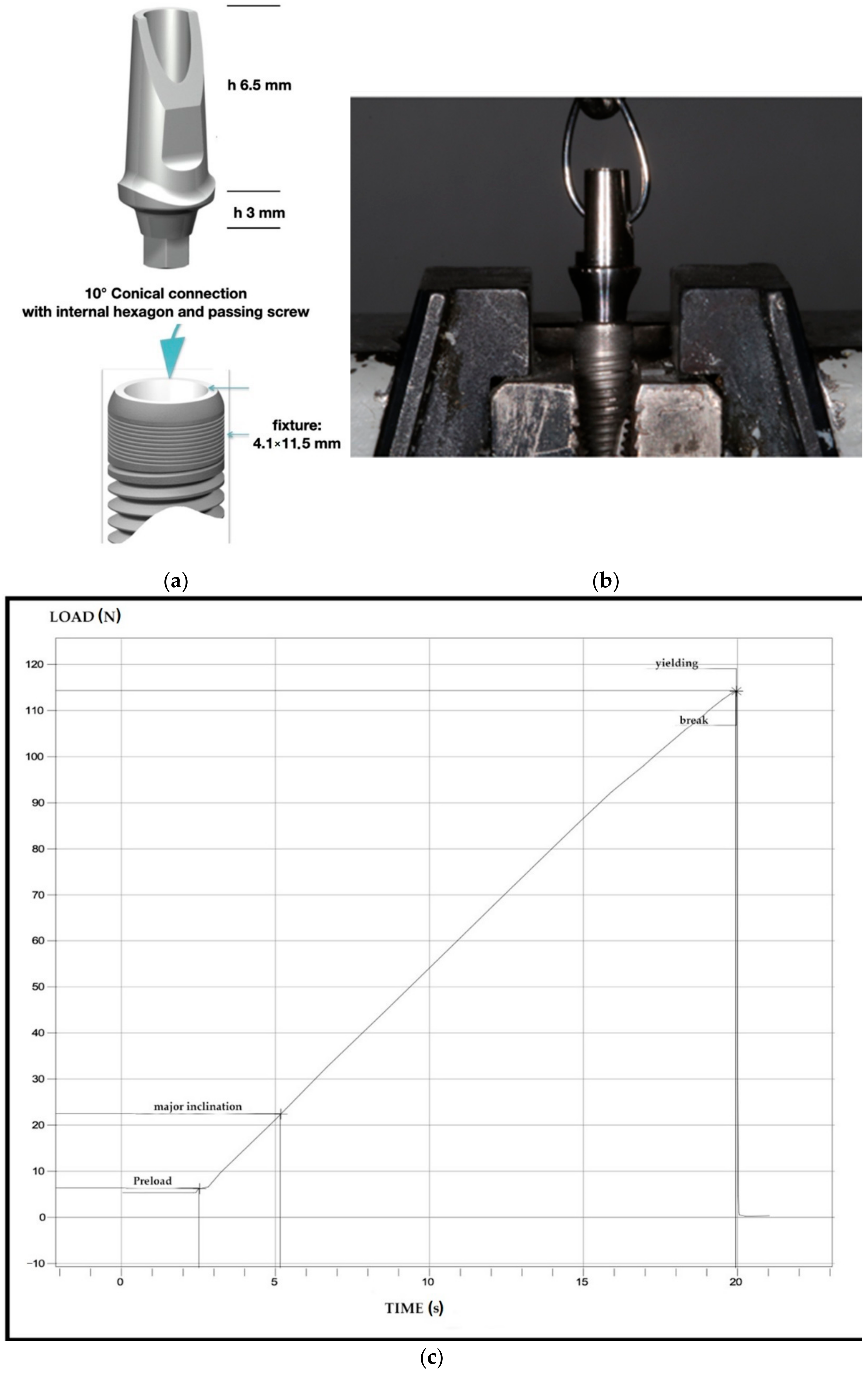
2.1. Implant-Abutment Systems Characteristics and Study Design
2.2. Mechanical Test
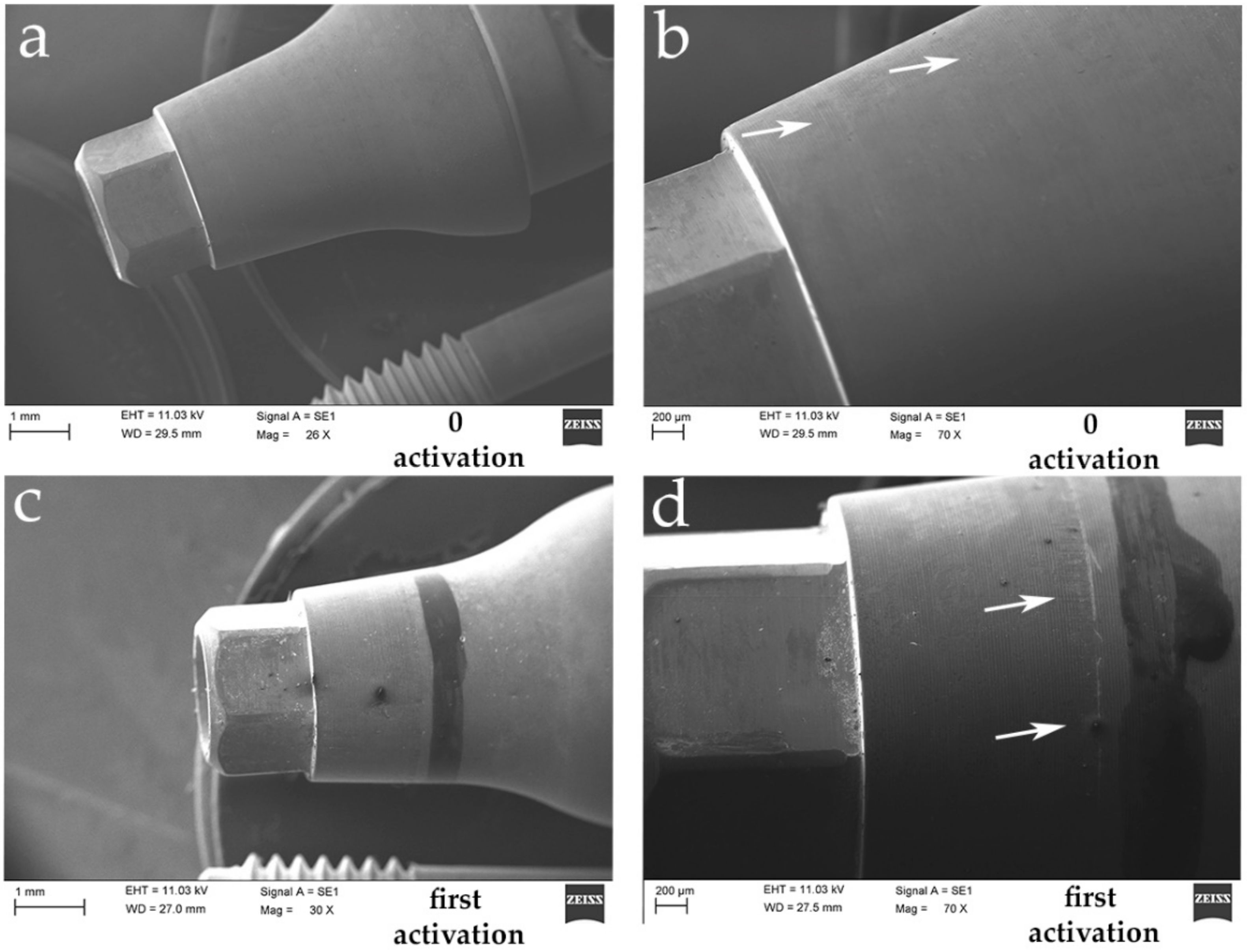
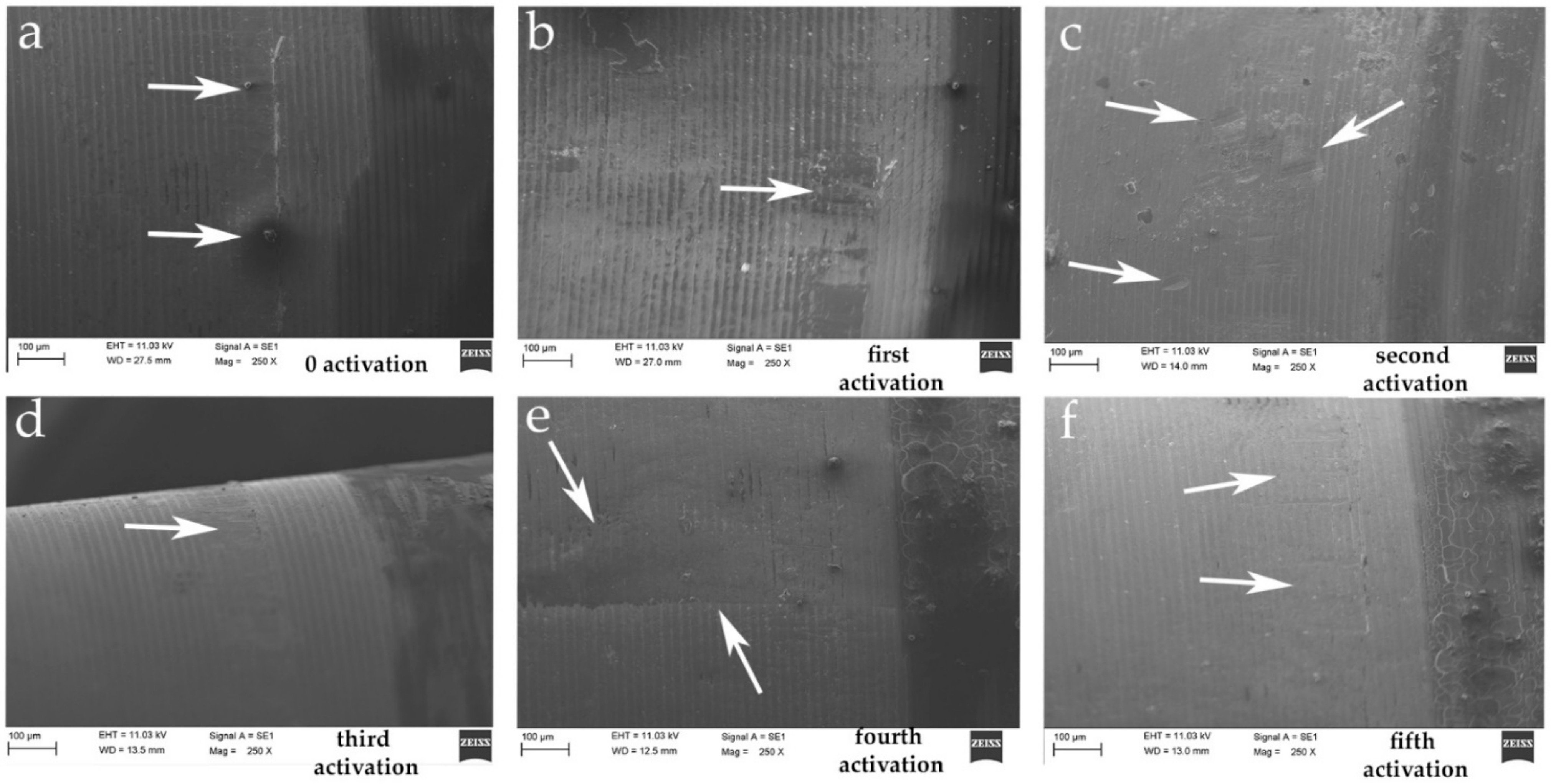
2.3. Scanning Electron Microscope (SEM) Test
2.4. Statistical Analysis
3. Results
4. Discussion
5. Conclusions
Author Contributions
Funding
Institutional Review Board Statement
Informed Consent Statement
Data Availability Statement
Acknowledgments
Conflicts of Interest
References
- Broggini, N.; McManus, L.M.; Hermann, J.S.; Medina, R.U.; Schenk, R.K.; Buser, D.; Cochran, D.L. Peri-implant inflammation defined by the implant-abutment interface. J. Dent. Res. 2006, 85, 473–478. [Google Scholar] [CrossRef] [PubMed]
- Sinjari, B.; D’Addazio, G.; De Tullio, I.; Traini, T.; Caputi, S. Peri-implant bone resorption during healing abutment placement: The effect of a 0.20% chlorhexidine gel vs. placebo—A randomized double blind controlled human study. BioMed Res. Int. 2018, 2018, 1–13. [Google Scholar] [CrossRef] [Green Version]
- Jung, R.E.; Zembic, A.; Pjetursson, B.E.; Zwahlen, M.; Thoma, D.S. Systematic review of the survival rate and the incidence of biological, technical, and aesthetic complications of single crowns on implants reported in longitudinal studies with a mean follow-up of 5 years. Clin. Oral Implant. Res. 2012, 23, 2–21. [Google Scholar] [CrossRef]
- Oh, T.-J.; Yoon, J.; Misch, C.E.; Wang, H.-L. The causes of early implant bone loss: Myth or science? J. Periodontol. 2002, 73, 322–333. [Google Scholar] [CrossRef] [PubMed]
- Albrektsson, T.O.; Johansson, C.B.; Sennerby, L. Biological aspects of implant dentistry: Osseointegration. Periodontol. 2000 1994, 4, 58–73. [Google Scholar] [CrossRef] [PubMed]
- Fu, J.-H.; Hsu, Y.-T.; Wang, H.-L. Identifying occlusal overload and how to deal with it to avoid marginal bone loss around implants. Eur. J. Oral Implant. 2012, 5, 91–103. [Google Scholar]
- Lang, N.P.; Berglundh, T. Periimplant diseases: Where are we now?-Consensus of the seventh European workshop on periodontology. J. Clin. Periodontol. 2011, 38, 178–181. [Google Scholar] [CrossRef] [Green Version]
- Caricasulo, R.; Malchiodi, L.; Ghensi, P.; Fantozzi, G.; Cucchi, A. The influence of implant-abutment connection to peri-implant bone loss: A systematic review and meta-analysis. Clin. Implant. Dent. Relat. Res. 2018, 20, 653–664. [Google Scholar] [CrossRef] [PubMed]
- Cairo, F.; Nieri, M.; Cavalcanti, R.; Landi, L.; Rupe, A.; Sforza, N.M.; Pace, R.; Barbato, L. Marginal soft tissue recession after lateral guided bone regeneration at implant site: A long-term study with at least 5 years of loading. Clin. Oral Implant. Res. 2020, 31, 1116–1124. [Google Scholar] [CrossRef] [PubMed]
- Papi, P.; Di Carlo, S.; Mencio, F.; Rosella, D.; De Angelis, F.; Pompa, G. Dental implants placed in patients with mechanical risk factors: A long-term follow-up retrospective study. J. Int. Soc. Prev. Community Dent. 2017, 7, S48–S51. [Google Scholar] [CrossRef] [PubMed] [Green Version]
- Ghinassi, B.; D’Addazio, G.; Di Baldassarre, A.; Femminella, B.; Di Vincenzo, G.; Piattelli, M.; Gaggi, G.; Sinjari, B. Immunohistochemical results of soft tissues around a new implant healing-abutment surface: A human study. J. Clin. Med. 2020, 9, 1009. [Google Scholar] [CrossRef] [Green Version]
- Scarano, A.; Assenza, B.; Piattelli, M.; Iezzi, G.; Leghissa, G.C.; Quaranta, A.; Tortora, P.; Piattelli, A. A 16–year study of the microgap between 272 human titanium implants and their abutments. J. Oral Implant. 2005, 31, 269–275. [Google Scholar] [CrossRef] [PubMed] [Green Version]
- Lauritano, D.; Moreo, G.; Lucchese, A.; Viganoni, C.; Limongelli, L.; Carinci, F. The impact of implant–Abutment connection on clinical outcomes and microbial colonization: A narrative review. Materials 2020, 13, 1131. [Google Scholar] [CrossRef] [Green Version]
- Goiato, M.C.; Pellizzer, E.P.; Da Silva, E.V.F.; Bonatto, L.D.R.; Dos Santos, D.M. Is the internal connection more efficient thanexternal connection in mechanical, biological, and esthetical point of views? A systematic review. Oral Maxillofac. Surg. 2015, 19, 229–242. [Google Scholar] [CrossRef] [PubMed]
- Finger, I.M.; Castellon, P.; Block, M.; Elian, N. The evolution of external and internal implant/abutment connections. Pract. Proced. Aesthet. Dent. 2003, 15, 625–632. [Google Scholar]
- Assenza, B.; Tripodi, D.; Scarano, A.; Perrotti, V.; Piattelli, A.; Iezzi, G.; D’Ercole, S. Bacterial leakage in implants with different implant-abutment connections: An in vitro study. J. Periodontol. 2012, 83, 491–497. [Google Scholar] [CrossRef] [PubMed]
- Staubli, N.; Walter, C.; Schmidt, J.C.; Weiger, R.; Zitzmann, N.U. Excess cement and the risk of peri-implant disease—A systematic review. Clin. Oral. Implant. Res. 2017, 28, 1278–1290. [Google Scholar] [CrossRef]
- Scarano, A.; Valbonetti, L.; Degidi, M.; Pecci, R.; Piattelli, A.; de Oliveira, P.S.; Perrotti, V. Implant-Abutment contact surfaces and microgap measurements of different implant connections under 3-Dimensional X-ray microtomography. Implant Dent. 2016, 25, 656–662. [Google Scholar] [CrossRef]
- Yao, K.T.; Kao, H.C.; Cheng, C.K.; Fang, H.W.; Huang, C.H.; Hsu, M.L. The potential risk of conical implant-abutment connections: The antirotational ability of cowell implant system. Clin. Implant Dent. Relat. Res. 2015, 17, 1208–1216. [Google Scholar] [CrossRef]
- Khongkhunthian, P.; Khongkhunthian, S.; Weerawatprachya, W.; Pongpat, K.; Aunmeungtong, W. Comparative study of torque resistance and microgaps between a combined Octatorx-cone connection and an internal hexagon implant-abutment connection. J. Prosthet. Dent. 2015, 113, 420–424. [Google Scholar] [CrossRef]
- Nam, R.K.; Lee, S.J.; Park, E.J.; Kwon, H.B.; Yoon, H.I. Three-dimensional deformation and wear of internal implant-abutment connection: A comparative biomechanical study using titanium and zirconia. Int. J. Oral Maxillofac. Implant. 2018, 33, 1279–1286. [Google Scholar] [CrossRef]
- Tallarico, M.; Fiorellini, J.; Nakajima, Y.; Omori, Y.; Takahisa, I.; Canullo, L. Mechanical outcomes, microleakage, and marginal accuracy at the implant-abutment interface of original versus nonoriginal implant abutments: A systematic review of in vitro studies. BioMed Res. Int. 2018, 2018, 2958982. [Google Scholar] [CrossRef] [PubMed] [Green Version]
- Varvara, G.; Sinjari, B.; Caputi, S.; Scarano, A.; Piattelli, M. The relationship between time of re-tightening and preload loss of abutment screws for two different implant designs: An in-vitro study. J. Oral Implant. 2019. [Google Scholar] [CrossRef] [PubMed]
- Sinjari, B.; D’Addazio, G.; Murmura, G.; Di Vincenzo, G.; Semenza, M.; Caputi, S.; Traini, T. Avoidance of interaction between impression materials and tooth surface treated for immediate dentin sealing: An in vitro study. Materials 2019, 12, 3454. [Google Scholar] [CrossRef] [PubMed] [Green Version]
- Sinjari, B.; D’Addazio, G.; Bozzi, M.; Santilli, M.; Traini, T.; Murmura, G.; Caputi, S. SEM analysis of enamel abrasion after air polishing treatment with erythritol, glycine and sodium bicarbonate. Coatings 2019, 9, 549. [Google Scholar] [CrossRef] [Green Version]
- Hsu, P.F.; Yao, K.T.; Kao, H.C.; Hsu, M.L. Effects of axial loading on the pull-out force of conical connection abutments in ankylos implant. Int. J. Oral Maxillofac. Implant. 2018, 33, 788–794. [Google Scholar] [CrossRef] [PubMed]
- Pintinha, M.; Camarini, E.T.; Sábio, S.; Pereira, J.R. Effect of mechanical loading on the removal torque of different types of tapered connection abutments for dental implants. J. Prosthet. Dent. 2013, 110, 383–388. [Google Scholar] [CrossRef]
- Yao, K.T.; Chen, C.S.; Cheng, C.K.; Fang, H.W.; Huang, C.H.; Kao, H.C.; Hsu, M.L. Optimization of the conical angle design in conical implant-abutment connections: A pilot study based on the finite element method. J. Oral Implantol. 2018, 44, 26–35. [Google Scholar] [CrossRef] [PubMed]
- Ricciardi Coppedê, A.; de Mattos, M.; Rodrigues, R.C.; Ribeiro, R.F. Effect of repeated torque/mechanical loading cycles on two different abutment types in implants with internal tapered connections: An in vitro study. Clin. Oral Implant. Res. 2009, 20, 624–632. [Google Scholar] [CrossRef]
- Kim, K.S.; Han, J.S.; Lim, Y.J. Settling of abutments into implants and changes in removal torque in five different implant-abutment connections. Part 1: Cyclic loading. Int. J. Oral Maxillofac Implant. 2014, 29, 1079–1084. [Google Scholar] [CrossRef] [Green Version]
- Bozkaya, D.; Müftü, S. Mechanics of the tapered interference fit in dental implants. J. Biomech. 2003, 36, 1649–1658. [Google Scholar] [CrossRef] [Green Version]
- Bozkaya, D.; Müftü, S. Efficiency considerations for the purely tapered interference fit (TIF) abutments used in dental implants. J. Biomech. Eng. 2004, 126, 393–401. [Google Scholar] [CrossRef]
- Murmura, G.; Di Iorio, D.; Cicchetti, A.R.; Sinjari, B.; Caputi, S. In vitro analysis of resistance to cyclic load and preload distribution of two implant/abutment screwed connections. J. Oral Implantol. 2013, 39, 293–301. [Google Scholar] [CrossRef]
- Cooper, L.F.; Tarnow, D.; Froum, S.; Moriarty, J.; De Kok, I.J. Comparison of marginal bone changes with internal conus and external hexagon design implant systems: A prospective, randomized study. Int. J. Periodontics Restor. Dent. 2016, 36, 631–642. [Google Scholar] [CrossRef]
- Assenza, B.; Artese, L.; Scarano, A.; Rubini, C.; Perrotti, V.; Piattelli, M.; Thams, U.; San Roman, F.; Piccirilli, M.; Piattelli, A. Screw vs cement-implant-retained restorations: An experimental study in the beagle. Part 2. Immunohistochemical evaluation of the peri-implant tissues. J. Oral Implant. 2006, 32, 1–7. [Google Scholar] [CrossRef]
- D’Ercole, S.; D’Addazio, G.; Di Lodovico, S.; Traini, T.; Di Giulio, M.; Sinjari, B. Porphyromonas Gingivalis load is balanced by 0.20% chlorhexidine gel. A randomized, double-blind, controlled, microbiological and immunohistochemical human study. J. Clin. Med. 2020, 20, 284. [Google Scholar] [CrossRef] [PubMed] [Green Version]
- Farmakis, I.K.; Potsika, V.T.; Smyris, A.F.; Gelalis, I.D.; Fotiadis, D.I.; Pakos, E.E. A biomechanical study of the effect of weight loading conditions on the mechanical environment of the hip joint endoprosthesis. Clin. Biomech. 2019, 70, 197–202. [Google Scholar] [CrossRef]
- Vinhas, A.S.; Aroso, C.; Salazar, F.; López-Jarana, P.; Ríos-Santos, J.V.; Herrero-Climent, M. Review of the mechanical behavior of different implant–abutment connections. Int. J. Environ. Res. Public Health 2020, 17, 8685. [Google Scholar] [CrossRef]
- Schmitt, C.M.; Nogueira-Filho, G.; Tenenbaum, H.C.; Lai, J.Y.; Brito, C.; Döring, H.; Nonhoff, J. Performance of conical abutment (Morse Taper) connection implants: A systematic review. J. Biomed. Mater. Res. A 2014, 102, 552–574. [Google Scholar] [CrossRef] [PubMed]
- Sinjari, B.; D’Addazio, G.; Traini, T.; Varvara, G.; Scarano, A.; Murmura, G.; Caputi, S. A 10-year retrospective comparative human study on screw-retained versus cemented dental implant abutments. J. Biol. Regul. Homeost. Agents 2019, 33, 787–797. [Google Scholar]
- De Moura, M.B.; Loureiro, K.; Lima, L.B.; Felippi, C.; Júnior, P. Biomechanical behavior of three different types of internal tapered connections after cyclic and static loading tests: Experimental in vitro. Int J. Implant. Dent. 2020, 6, 41. [Google Scholar] [CrossRef]
- Bozkaya, D.; Müftü, S. Mechanics of the taper integrated screwed-in (TIS) abutments used in dental implants. J. Biomech. 2005, 38, 87–97. [Google Scholar] [CrossRef] [Green Version]
- Lee, J.H.; Lee, W.; Huh, Y.H.; Park, C.J.; Cho, L.R. Impact of intentional overload on joint stability of internal implant-abutment connection system with dierent diameter. J. Prosthodont. 2019, 28, 649–656. [Google Scholar] [CrossRef]
- Ko, K.H.; Huh, Y.H.; Park, C.J.; Cho, L.R. Axial displacement in cement-retained prostheses with different implant-abutment connections. Int. J. Oral Maxillofac. Implant. 2019, 34, 1098–1104. [Google Scholar] [CrossRef]

| Descriptive Statistic | Abutment Activation | ||||
|---|---|---|---|---|---|
| First | Second | Third | Fourth | Fifth | |
| Measurements (n) | 40 | 40 | 40 | 40 | 40 |
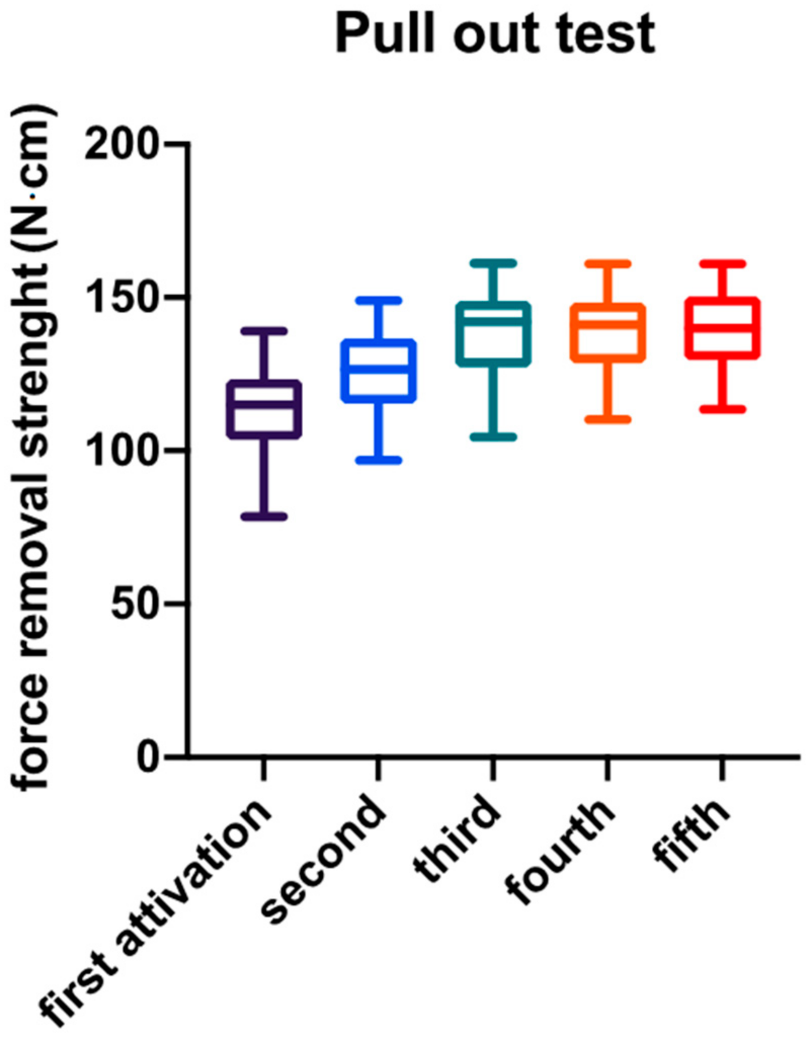
| Minimum | 78.54 | 96.87 | 104.4 | 110.2 | 113.5 |
| 25% Percentile | 103.5 | 115.4 | 127.2 | 128.6 | 129.4 |
| Median | 114.9 | 126.6 | 142.0 | 141.1 | 140.0 |
| 75% Percentile | 123.4 | 136.8 | 148.8 | 148.3 | 150.4 |
| Maximum | 139.1 | 149.1 | 161.2 | 161.0 | 161.0 |
| Mean | 113.9 | 126.1 | 138.1 | 138.8 | 140.0 |
| Std. Deviation | 13.02 | 12.81 | 15.15 | 11.90 | 12.99 |
| Std. Error of Mean | 2.059 | 2.025 | 2.396 | 1.881 | 2.053 |
| Lower 95% CI | 109.7 | 122.0 | 133.3 | 135.0 | 135.8 |
| Upper 95% CI | 118.0 | 130.2 | 143.0 | 142.6 | 144.1 |
| Comparison | Tukey’s Multiple Comparisons Test | |||
|---|---|---|---|---|
| Mean Difference | 95% Confidence Interval of Difference | Significance | Level of Significance | |
| 1° vs. 2° | −12.20 | −20.33 to −4.058 | 0.0005 | *** |
| 1° vs. 3° | −24.23 | −32.37 to −16.10 | <0.0001 | **** |
| 1° vs. 4° | −24.89 | −33.02 to −16.75 | <0.0001 | **** |
| 1° vs. 5° | −26.08 | −34.21 to −17.94 | <0.0001 | **** |
| 2° vs. 3° | −12.04 | −20.18 to −3.901 | 0.0006 | *** |
| 2° vs. 4° | −12.69 | −20.83 to −4.554 | 0.0003 | *** |
| 2° vs. 5° | −13.88 | −22.02 to −5.745 | <0.0001 | **** |
| 3° vs. 4° | −0.6530 | −8.790 to 7.484 | 0.9995 | ns |
| 3° vs. 5° | −1.844 | −9.981 to 6.293 | 0.9711 | ns |
| 4° vs. 5° | −1.191 | −9.328 to 6.946 | 0.9944 | ns |
Publisher’s Note: MDPI stays neutral with regard to jurisdictional claims in published maps and institutional affiliations. |
© 2021 by the authors. Licensee MDPI, Basel, Switzerland. This article is an open access article distributed under the terms and conditions of the Creative Commons Attribution (CC BY) license (http://creativecommons.org/licenses/by/4.0/).
Share and Cite
D’Addazio, G.; Sinjari, B.; Arcuri, L.; Femminella, B.; Murmura, G.; Santilli, M.; Caputi, S. Mechanical Pull-Out Test of a New Hybrid Fixture-Abutment Connection: An In Vitro Study. Materials 2021, 14, 1555. https://doi.org/10.3390/ma14061555
D’Addazio G, Sinjari B, Arcuri L, Femminella B, Murmura G, Santilli M, Caputi S. Mechanical Pull-Out Test of a New Hybrid Fixture-Abutment Connection: An In Vitro Study. Materials. 2021; 14(6):1555. https://doi.org/10.3390/ma14061555
Chicago/Turabian StyleD’Addazio, Gianmaria, Bruna Sinjari, Lorenzo Arcuri, Beatrice Femminella, Giovanna Murmura, Manlio Santilli, and Sergio Caputi. 2021. "Mechanical Pull-Out Test of a New Hybrid Fixture-Abutment Connection: An In Vitro Study" Materials 14, no. 6: 1555. https://doi.org/10.3390/ma14061555
APA StyleD’Addazio, G., Sinjari, B., Arcuri, L., Femminella, B., Murmura, G., Santilli, M., & Caputi, S. (2021). Mechanical Pull-Out Test of a New Hybrid Fixture-Abutment Connection: An In Vitro Study. Materials, 14(6), 1555. https://doi.org/10.3390/ma14061555