Article

Spectral and Angular Characteristics of the High-Contrast Dielectric Grating under the Resonant Interaction of a Plane Wave and a Gaussian Beam

1
INFN-Laboratori Nazionali di Frascati, Via E. Fermi 54, 00044 Frascati, Italy
2
Department of Photonics, Lviv Polytechnic National University, S. Bandera Str. 12, 79013 Lviv, Ukraine
3
Institute of Physics of NAS of Ukraine, Prospect Nauky, 46, 03028 Kyiv, Ukraine
4
Department of Physics, University of Rzeszow, Pigonia Str. 1, 35959 Rzeszow, Poland
*
Authors to whom correspondence should be addressed.
Materials 2022, 15(10), 3529; https://doi.org/10.3390/ma15103529
Submission received: 17 March 2022 / Revised: 30 April 2022 / Accepted: 12 May 2022 / Published: 14 May 2022

Abstract

:
The resonant interaction of a plane wave and a one-dimensional Gaussian beam with a high-contrast dielectric grating was analyzed. Rigorous coupled wave analysis (RCWA) was used to numerically model the diffraction of a plane wave by the grating. RCWA, a discrete Fourier transform at the fulfillment (of the conditions) of the sampling theorem, was used to study diffraction of the Gaussian beam. The grating can be considered as a one-dimensional photonic crystal along which the waveguide mode propagates under resonance. The corresponding photonic crystal has both allowed and forbidden photonic bands for the propagating waveguide mode under resonance due to the high-contrast dielectric permittivity. There is no significant difference between the spectral and angular characteristics under the interaction of the plane wave or the Gaussian beam with grating, if the waveguide mode is in the forbidden photonic bandgap. The reflection coefficient from the grating is practically equal to unity for both cases. Resonant spectral and angular characteristics become wider at the Gaussian beam diffraction compared to the resonance curves for the plane wave in the case when the waveguide mode is in the allowed photon bandgap. The reflection coefficient from the grating becomes less than unity and its value tends to unity when the Gaussian beam width increases.

1. Introduction

In recent years, intensive studies of refractive index sensors based on the dielectric grating on dielectric substrates have been carried out [1,2,3,4]. These sensors are based on the waveguide mode resonance [5,6,7] by the dielectric gratings on the dielectric substrates. The reflection coefficient from a periodic structure is equal to unity under the resonant interaction of an incident plane wave and grating [8,9,10]. The operation principle of such sensors is based on a change in the resonant wavelength of the incident wave or the resonant angle of the beam incidence by the gratings with the change in the refractive index of the studied surrounding medium [3,10,11].
The predominantly numerical studies of the diffraction of a plane wave by the grating were carried out using rigorous coupled wave analysis (RCWA) [12] with numerically stable algorithms [13,14,15]. The RCWA is asymptotically accurate [13] and converges faster than the other methods for dielectric periodic structures. It is used to analyze various periodic structures [16,17], including photonic crystals [18].
However, the results obtained using RCWA for the resonant interaction of a plane wave with a dielectric grating often did not coincide with the experimental data [2,19]. It is obvious that the grating was irradiated not by a plane wave but by a finite cross-section beam in the experiments. It should be noted that the resonant wavelengths, experimentally determined and numerically predicted, coincide with satisfactory accuracy. At the same time, the reflection coefficients determined experimentally are significantly less than unity, but significantly higher than the values ( R > 0.1 ), which can be explained by Fresnel reflection. Simultaneously, the widths of the experimentally measured spectral resonance curves increased. This discrepancy between the numerically predicted and experimental results can be explained by the following reasons:
(a) there is no strict repeatability of the groove shape and the period of the grating in the real grating, which was especially important in [19];
(b) the grating was irradiated by a finite cross-section beam during the experimental studies. The beam width can be much less than the distance over which the resonant waveguide mode propagates into the gratings. It is important for a slight refractive index modulation of the grating medium [2,16]. Therefore, it is important to numerically study the interaction of a finite cross-section beam with the dielectric grating, under waveguide resonance.
This problem has been analyzed in a relatively small number of scientific works. Apparently, this is due to the fact that the result of the diffraction of a finite cross-section beam by the grating almost coincides with the result of the diffraction of the plane wave in the absence of resonance [20].
The studies of the diffraction of the finite size beam from three to 20 periods of using the finite-difference frequency-domain method were presented in [21]. The influence of beams limited in transverse size by the rigorous boundary element method was studied using the rigorous boundary element method in [22]. According to the simple scalar theory of diffraction, it was explained that the angular anomaly of the reflected beam from the grating is a direct result of the finite size of the beam [23]. In [24], a study of beam diffraction using a metal grating of finite size, under excitation of the surface plasmon–polariton resonances, was carried out. Theoretical modeling suggests an expansion of the resonances when the grating size decreases. The resonant filter for telecommunications based on gratings finite in size has been developed, which is tuned due to the change in the incidence angle of the beam by the gratings [25]. It was shown in [26] that the fields of Gaussian beams scattered by reflective gratings differ markedly from those predicted by geometrical considerations. A corrected theory of diffraction [27] by a finite volume grating, which is rather complicated for practical use, was proposed. The influence of the finite size of the incident Gaussian beam on the spectrum of anomalous reflection and the shape of the energy distribution in the reflected beam from the waveguide with the grating was analyzed using the developed approximate theory [28]. The authors of [29] attempted to extend the RCWA method for a grating with a finite number of periods using supercells. Guizal et al. [30] developed a method called aperiodic RCWA, in which the permittivity of the finite grating is represented by a Fourier integral leading to an integral–differential equation. Lalanne and coworkers [31,32] introduced the use of absorbing boundary conditions and ideal layer matching at the unit cell ends, to numerically analyze the finite periodic structures. The simplest and rather effective theory of the reflection of the finite size beam from the grating was given in [33], where the solution was provided in the analytical form. This theory consists of decomposing the limited beam into plane waves. The direct and inverse transformations are used in the analysis. This theory does not imply a search for the spatial distribution of the amplitude and, accordingly, the power of the wave passes through the gratings. Therefore, it is impossible to check whether the law of energy conservation is fulfilled during diffraction by the purely phase grating. Further development of the theory of limited light beam diffraction by the dielectric grating was presented in [34]. The method is based on the representation of such a beam as an expansion into plane waves using the Fourier transform. Then, the amplitude reflection and transmission coefficients of RCWA are determined for each plane wave. The field distribution of the reflected and transmitted beams is determined by the inverse discrete Fourier transform [35]. The number of plane waves into which a limited light beam is decomposed must correspond to the sampling theorem [36,37]. The developed method [34] corresponds to the energy conservation law, if the grating is dielectric [38] at the diffraction of the finite cross section beam. Thus, the sum of the powers of reflected and transmitted beams is equal to the power of the incident beam on the grating. Results of studies of finite beam diffraction by non-absorbing gratings obtained by the holographic method using the photosensitive media were obtained using this method [20,34]. Such gratings are characterized by the low modulation of the grating medium refractive index. In [20], diffraction analysis of the one-dimensional Gaussian beam and the beam described by the rect ( x ) [35] function was performed. Experimental data [20] of the reflection coefficient dependence on the beam width coincided well with the corresponding dependence obtained by the numerical method, according to the developed theory.
A sensor based on a relief dielectric grating with a rectangular bar cross-section was characterized by unique properties [4]. The lower refractive index was 1.333 (the refractive index of the tested medium), and the higher refractive index was 2.0 at the fill factor F = 0.5 in this grating. It turned out that such a structure had some unexpected properties. The full width at half maximum (FWHM) decreased sharply (approximately from 20 nm to 0.15 nm) [4] at almost constant sensitivity S ~ 250   nm / RIUU and accordingly increased the figure of merit (FOM), which can be defined as FOM = S/FWHM [39] for certain grating parameters (grating period and thickness, wavelength). The FOM increased from 14 to 1620. Such features of this periodic structure were explained in [40], in which an analysis of diffraction was performed using numerical methods for the plane wave and the Gaussian beam. A comparison of the obtained results allowed us to conclude that the grating under the waveguide mode resonance, with respect to the high reflection coefficient from the grating, should be considered as a one-dimensional photonic crystal [41]. Such a high-contrast photonic crystal can have both forbidden and allowed photonic bandgaps [41,42]. There is no bandgap [41] in the case of low dielectric contrast in the photonic crystal. Thus, such sensors will have a high FOM [2,20,34].
It was found that FOMs are equal in wavelength and angle, both for a plane wave [2] and for the limited beam in cross-section [20,34] for sensors based on the holographic gratings (small modulation of the grating medium refractive index). In addition, it was shown that FWHM for the plane wave is uniquely related by the analytical expression linking wavelength, grating period, beam angle, and wavelength attenuation constant of waveguide mode at the propagation by the grating [20]. Moreover, the constant attenuation was determined at the grating irradiation by the Gaussian beam. However, it is not certain that these provisions will be valid for gratings with high-contrast changes in dielectric constant over a period. Allowed and forbidden photonic bandgaps are possible in such gratings in one-dimensional photonic crystals. Therefore, it is desirable to continue numerous studies in its irradiation with the plane wave and the Gaussian beam. These studies should be aimed at obtaining the spectral and angular dependences of the reflection coefficient from the grating, with various parameters ( L ,   d ,   θ ,   λ ), as well as the changes in the resonant wavelength and the resonant angle, upon changes in the surrounding medium refractive index. According to the results of these studies, it is important to determine the angular and spectral sensitivity, as well as FWHM and FOM, and how they depend on the Gaussian beam width L, for the allowed and forbidden photonic bandgaps.

2. Results of Numerical Modeling and Discussions

The method described in detail in [20,34,40] was used to analyze the diffraction of the Gaussian beam by the dielectric grating. The notation of physical quantities in this paper is the same as in [40]. The researched periodic structure with the corresponding symbols is shown in Figure 1. The red arrow in the figure schematically shows the waveguide mode propagating from right to left, which loses its energy when interacting with the grating; as a result, the reflected and missed beams are formed.
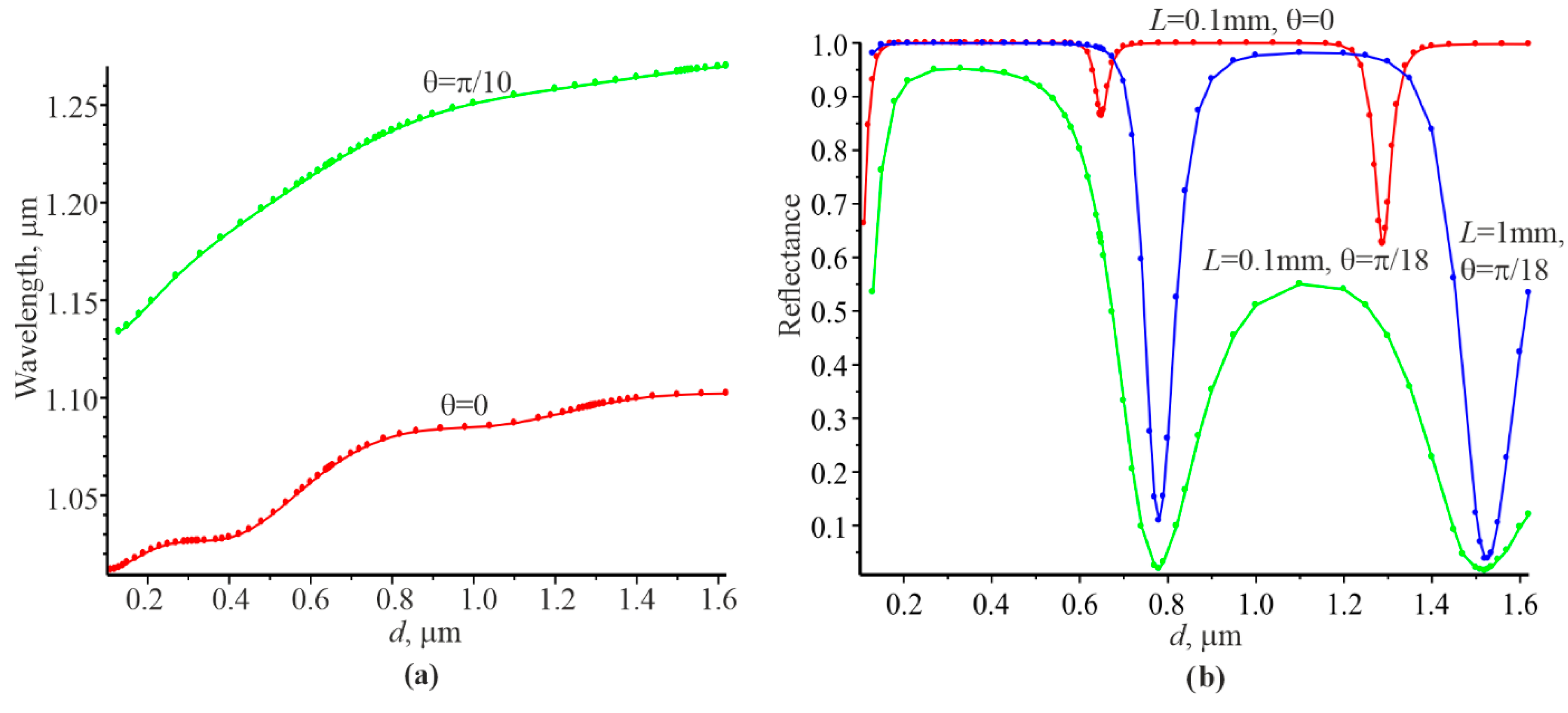
The graphical materials (Figure 2) and the corresponding numerical data given in [40] were used for our study.
Each grating thickness d has its own resonant wavelength λ r e z at which the reflection coefficient is equal to unity, as follows from Figure 2a. It can be seen that the resonant wavelengths are higher than at the normal incidence of the plane wave at the incidence angle of the plane wave = π / 18 . Figure 2b indicates that the reflection coefficient P r takes on minimum values at certain thicknesses corresponding to λ r e z according to Figure 2a: d = 0.65   μ m and d = 1.288   μ m for θ = 0 and d = 0.78   μ m and d = 1.52   μ m for θ = π / 18 . Therefore, it can be argued that the corresponding λ r e z values are in the photonic allowed bandgap according to the theory of photonic crystals. At the same time, reflection coefficient P r is practically equal to unity for a wide range of thicknesses d , even for the Gaussian beam width L = 0.1   mm . That is, these thicknesses and the corresponding resonant wavelengths are in the forbidden photonic bandgap.
The spectral dependences of the reflection coefficient on the grating are shown in Figure 3. The reflection spectrum for the Gaussian beam, i.e., the solid red curve, coincides with the blue circles, corresponding to the plane wave at the thickness d = 1   μ m (Figure 3a, photonic bandgap).
The spectral curves under conditions when the waveguide mode is in the allowed photon bandgap and can propagate a considerable distance in the grating are shown in the Figure 3b–d.
It can be concluded that the reflection coefficient P r ( λ ) increases when L increases and approaches the spectral curve at L = (Figure 3b). There is also a clear correlation between the reflection coefficient at resonance for the Gaussian beam in accordance with Figure 2a and the width of the spectral curve for the plane wave. That is, a smaller reflection coefficient P r for a Gaussian beam results in a smaller width of the spectral curve for the plane wave.
The widths of the spectral resonance curves at the level of 0.5 at the incidence of the plane wave and the Gaussian beam ( δ λ ≡ FWHM) were determined using Figure 3. The attenuation indices γ at the propagation of the resonant waveguide mode in the grating were determined for the linear sections of the curves ln | r 0 ( x ) | . These data are presented in Table 1 (columns 4 and 5, respectively).
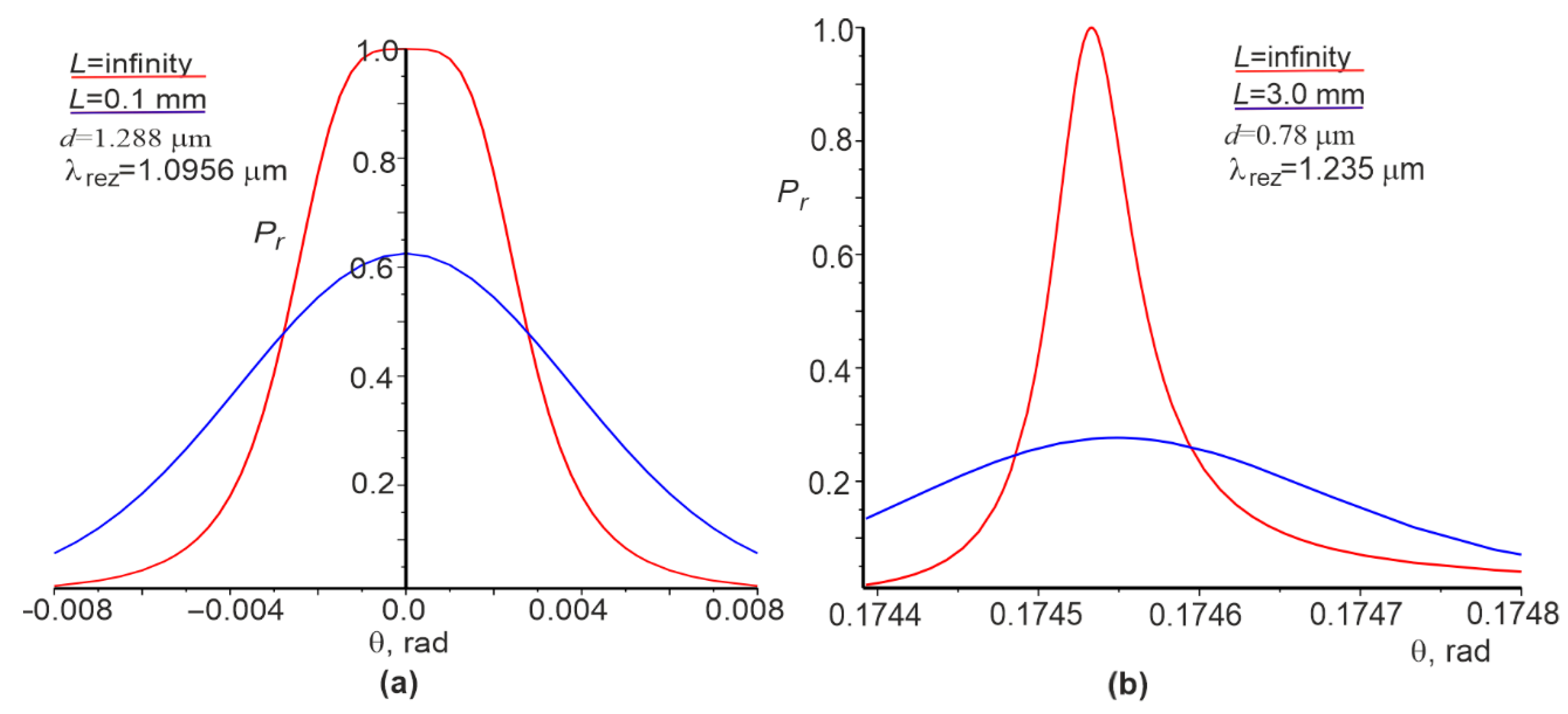
The angular dependences of the reflection coefficient for the plane wave and the Gaussian beam are shown in Figure 4. It can be seen that angular dependence has a somewhat flat vertex (Figure 4a, red curve) at the normal incidence of the plane wave. However, it is absent for other cases. The widths of the angular dependences δ θ are given in column 6 of Table 1. There is a clear correlation between the widths δ λ and δ θ for the plane wave and the attenuation index γ ; a smaller γ results in a narrower δ λ and δ θ for the plane wave.
The dependences of the change in the resonant wavelength Δ λ r e z on the change in the refractive index Δ n 1 for the Gaussian beam and the plane wave at other constant parameters are also interesting. The corresponding dependencies are shown in Figure 5. These dependences are linear in nature, and they can be used to determine the spectral sensitivity S λ = Δ λ r e z / Δ n 1 . It can be argued that the sensitivities S λ are the same for the Gaussian beam and the plane wave since the red and green circles lie on the same straight line (see Figure 5). This is consistent with the findings in [34], where the same result was obtained but for a low modulation dielectric constant of the grating medium. It can be concluded on the basis of the data in Table 1 that S λ values are slightly larger at the normal incidence of the Gaussian beam or plane wave compared to the angle of incidence π / 18 .
The spectral sensitivities S λ for some cases are shown in Table 1, column 7. Knowing S λ and δ λ , we determined FOM = S λ / δ λ , as presented in Table 1 (column 8). It can be seen that FOMs are mostly larger among the studied cases at the beam angle of incidence on the grating of π / 18 .
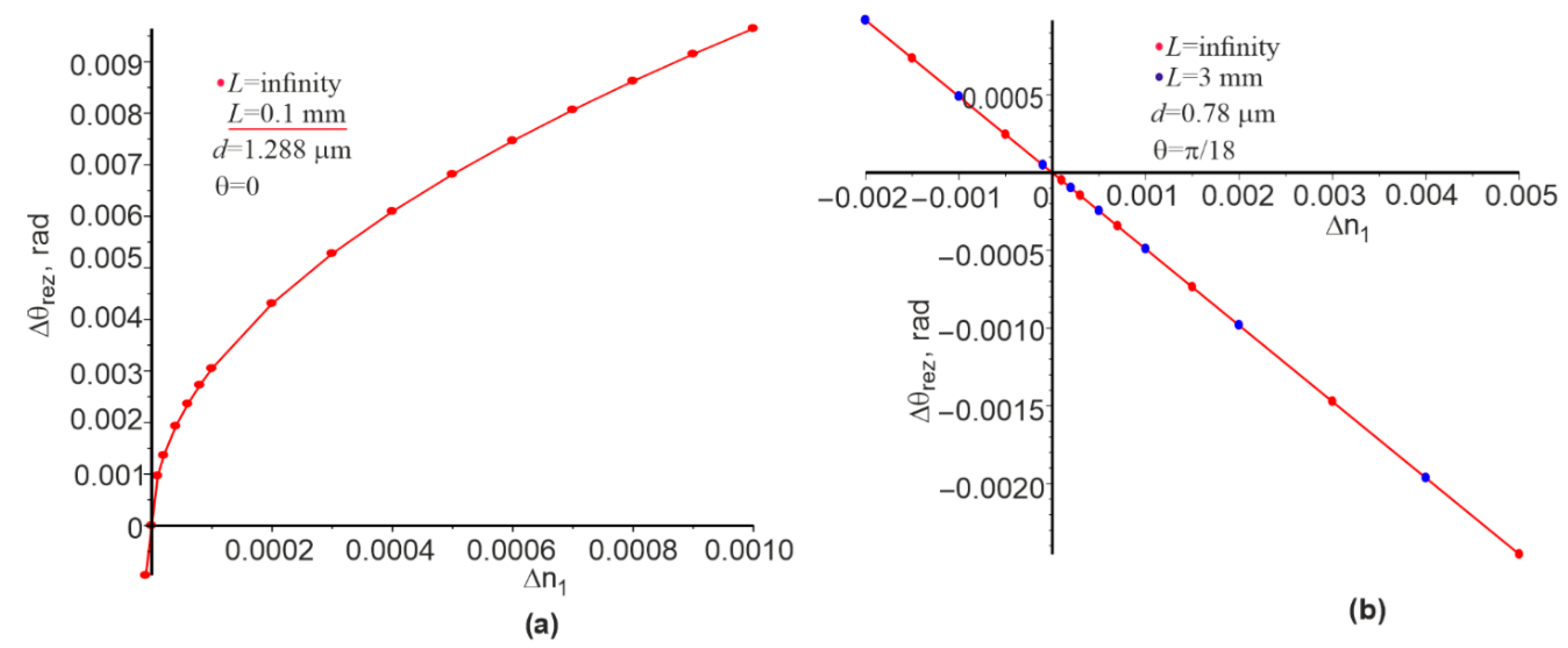
The dependences of the change in the resonance angle Δ θ r e z on the change in the refractive index Δ n 1 for the Gaussian beam and the plane wave at other constant parameters are shown in Figure 6. The nature of the corresponding curves significantly depends on the initial value of the angle. If the angle of incidence of the beams at n 1 = 1.333 is zero, then the corresponding dependence is nonlinear (Figure 6a). If the angle of incidence of the beams is equal to π / 18 , then the corresponding dependence is linear in the range of Δ n 1 from 0.002 to 0.005 , allowing us to calculate S θ = Δ θ / Δ n 1 . Results of the calculation of S θ for the angle of π / 18 are included in column 9 of Table 1. The ratio FOM θ = S θ / δ θ can be calculated knowing the values S θ , which are given in column 10 of Table 1. It can be expressed that
S λ / δ λ S θ / δ θ .
Equation (1) was obtained in [11] analytically for dielectric gratings based on photopolymer compositions, which are characterized by insignificant modulation of the refractive index of the grating medium. Equation (1) is also true for sensors based on a prism structure and based on metal gratings on the metal substrate in which surface plasmon–polariton waves are excited [11]. Moreover, Equation (1) is valid both for the plane wave (columns 8 and 10, lines 1 and 3) and for the cross-section limited beam (columns 8 and 10, lines 2 and 4). However, we can consider the S θ at the beam incidence angle on the grating significantly different from zero, as evidenced by Figure 6. Therefore, some of the cells of Table 1 are not filled for cases where the normal incidence of the plane wave or the Gaussian beam is on the grating.
It follows from Table 1 (columns 8 and 10) that the FOM in the transition from the plane wave to the Gaussian beam decreases several times due to increasing δ λ and δ θ at constant sensitivities S λ and S θ (columns 7 and 9, respectively). However, the FOM is large enough at the L shown in column 11, except for the data of rows 9 and 10, which correspond to the photon bandgap. In this case, the FOM is very small (41.7) due to the high value of δ λ = 11.5   nm .
Analytical expressions defining δ λ and δ θ for the plane wave for gratings with small modulation of the refractive index through Λ λ θ , and especially γ , which is determined for the Gaussian beam on the linear part of the ln | r 0 ( x ) | dependence, were presented in [33]. The corresponding equations are as follows:
δ λ λ Λ γ 2 π .
δ θ λ γ 2 π cos θ .
Numerical experiments have confirmed the validity of these equations for three-dimensional phase gratings with low modulation of the grating medium refractive index [20,34]. However, these relations are not fulfilled for our case when n 1 = 1.333 and n 2 = 2.0 . Here, δ λ = 0.037   nm , δ θ = 0.0624   mrad , and δ θ = 0.0624   mrad according to row 1 of Table 1 and δ λ = 0.021   nm and δ θ = 0.031   mrad according to Equations (2) and (3).
However, Equations (2) and (3) can be useful in another aspect. If certain grating parameters ( n 1 ,   n 2 , F ,   Λ , wavelength, and beam incident angle on the grating) correspond to a certain reflection coefficient, then the reflection coefficient does not change upon changing the wavelength λ , period Λ , grating thickness d , or beam width L   K times. The value of K can be either larger or smaller than one. This statement is true for both the plane wave ( L = ) and the beam of width L . However, numerical experiments have shown that γ will change 1 / K times. Therefore, we can assume that, when the parameters change K times, δ λ will also change K times, and δ θ will be unchanged in accordance with Equations (2) and (3). This was confirmed by our numerical experiments for data rows 1–8 of Table 1. Numerical experiments also showed that S λ also will change K times, while S θ will remain unchanged. Therefore, the FOM with such a change in parameters will remain unchanged, which is consistent with Equation (1).
The obtained relations can be called rules of similarity. They can be useful in determining the grating parameters to obtain the resonance at the certain wavelength generated by the laser, if the resonance conditions are known at the specific wavelength. Accordingly, the coefficient of change K will be equal to the ratio of the two wavelengths.

3. Conclusions

The obtained numerical results confirm the concept of the resonant waveguide mode propagation in the grating of a one-dimensional photonic crystal.
The values of FWHM for the plane wave and the Gaussian beam (rows 9 and 10, column 4 of Table 1) are the same and relatively wide (Figure 3a) if the waveguide mode is in the forbidden photon bandgap. Otherwise, when the waveguide mode is within the allowed photon bandgap, FWHM decreases with increasing L and approaches FWHM for the plane wave.
Numerical studies have shown that the dependences λ r e z and θ r e z are linear to change n 1 (see Figure 5b and Figure 6b) at the beam incidence angle of θ = π / 18 rad. However, θ r e z is nonlinear on n 1 at the initial angle θ = 0 (see Figure 6a). The corresponding sensitivities S λ and S θ , as well as FOM for both cases, which satisfy Equation (1), can be calculated on the basis of these linear dependences. However, Equations (2) and (3) are not valid for a large contrast of changes in the dielectric permittivity in the grating. Nevertheless, the right and left parts of these relations are within the same order of magnitude; in this particular case, they differ by about two times.
It is shown that the similarity rule is also valid for the limited beam in width. According to this rule, the reflection coefficient will not change when the wavelength λ , the period Λ , the grating thickness d , and the beam width L change K times. Therefore, δ λ will change K times and δ θ will remain unchanged, while S λ will also change K times and S θ will remain unchanged. Therefore, the FOM will remain unchanged with such a change in parameters, which is consistent with Equation (1).

Author Contributions

Conceptualization, S.B. and V.F.; methodology, V.F. and T.S.; formal analysis, Y.B. and I.Y.; investigation, V.F. and O.V.; validation, S.B.; resources, S.B.; writing—original draft preparation, V.F.; writing—review and editing, I.Y. and S.B.; supervision, V.F. and S.B. All authors have read and agreed to the published version of the manuscript.

Funding

This research received no external funding.

Informed Consent Statement

Not applicable.

Data Availability Statement

Data are available by the corresponding authors, upon reasonable request.

Conflicts of Interest

The authors declare no conflict of interest.

References

  1. Xu, Y.; Bai, P.; Zhou, X.; Akimov, Y.; Png, C.E.; Ang, L.-K.; Knoll, W.; Wu, L. Optical Refractive Index Sensors with Plasmonic and Photonic Structures: Promising and Inconvenient Truth. Adv. Opt. Mater. 2019, 7, 1801433. [Google Scholar] [CrossRef]
  2. Smirnova, T.; Fitio, V.; Sakhno, O.; Yezhov, P.; Bendziak, A.; Hryn, V.; Bellucci, S. Resonant and Sensing Performance of Volume Waveguide Structures Based on Polymer Nanomaterials. Nanomaterials 2020, 10, 2114. [Google Scholar] [CrossRef] [PubMed]
  3. Quaranta, G.; Basset, G.; Martin, O.J.F.; Gallinet, B. Recent Advances in Resonant Waveguide Gratings. Laser Photonics Rev. 2018, 12, 1800017. [Google Scholar] [CrossRef]
  4. Zhou, Y.; Wang, B.; Guo, Z.; Wu, X. Guided Mode Resonance Sensors with Optimized Figure of Merit. Nanomaterials 2019, 9, 837. [Google Scholar] [CrossRef] [Green Version]
  5. Wang, S.S.; Magnusson, R. Theory and applications of guided-mode resonance filters. Appl. Opt. 1993, 32, 2606–2613. [Google Scholar] [CrossRef]
  6. Magnusson, R.; Ko, Y.H. Guided-Mode Resonance Nanophotonics: Fundamentals and Applications. In Nanoengineering: Fabrication, Properties, Optics, and Devices XIII; SPIE: Bellingham, WA, USA, 2016; Volume 9927, p. 992702. [Google Scholar]
  7. Norton, S.M.; Morris, G.M.; Erdogan, T. Experimental investigation of resonant-grating filter lineshapes in comparison with theoretical models. J. Opt. Soc. Am. A 1998, 15, 464–472. [Google Scholar] [CrossRef]
  8. Destouches, N.; Pommier, J.-C.; Parriaux, O.; Clausnitzer, T.; Lyndin, N.; Tonchev, S. Narrow band resonant grating of 100% reflection under normal incidence. Opt. Express 2006, 14, 12613. [Google Scholar] [CrossRef] [Green Version]
  9. Tamulevičius, T.; Šeperys, R.; Andrulevičius, M.; Tamulevičius, S. Total internal reflection based sub-wavelength grating sensor for the determination of refractive index of liquids. Photonics Nanostruct. Fundam. Appl. 2011, 9, 140–148. [Google Scholar] [CrossRef]
  10. Anderson, B.B.; Brodsky, A.M.; Burgess, L.W. Threshold effects in light scattering from a binary diffraction grating. Phys. Rev. E 1996, 54, 912–923. [Google Scholar] [CrossRef]
  11. Bellucci, S.; Fitio, V.M.; Yaremchuk, I.; Vernyhor, O.; Bendziak, A.; Bobitski, Y. Comparison of the Optical Planar Waveguide Sensors’ Characteristics Based on Guided-Mode Resonance. Symmetry 2020, 12, 1315. [Google Scholar] [CrossRef]
  12. Moharam, M.G.; Gaylord, T.K. Rigorous coupled-wave analysis of grating diffraction—E-mode polarization and losses. J. Opt. Soc. Am. 1983, 73, 451–455. [Google Scholar] [CrossRef]
  13. Moharam, M.G.; Gaylord, T.K.; Grann, E.B.; Pommet, D.A. Formulation for stable and efficient implementation of the rigorous coupled-wave analysis of binary gratings. J. Opt. Soc. Am. A 1995, 12, 1068–1076. [Google Scholar] [CrossRef]
  14. Li, L. Formulation and comparison of two recursive matrix algorithms for modeling layered diffraction gratings. J. Opt. Soc. Am. A 1996, 13, 1024–1035. [Google Scholar] [CrossRef] [Green Version]
  15. Yaremchuk, I.; Tamulevičius, T.; Fitio, V.; Gražulevičiūte, I.; Bobitski, Y.; Tamulevičius, S. Numerical implementation of the S-matrix algorithm for modeling of relief diffraction gratings. J. Mod. Opt. 2013, 60, 1781–1788. [Google Scholar] [CrossRef]
  16. Fitio, V.M.; Sakhno, O.V.; Smirnova, T.N. Analysis of the diffraction by the gratings generated in the materials with a nonlinear response. Optik 2008, 119, 236–246. [Google Scholar] [CrossRef]
  17. Fitio, V.M. Transmissions of Metallic Gratings with Narrow Slots. In Proceedings of the 2006 International Workshop on Laser and Fiber-Optical Networks Modeling, Kharkiv, Ukraine, 29 June–1 July 2006; Volume 4018, pp. 113–116. [Google Scholar] [CrossRef]
  18. Dansas, P.; Paraire, N. Fast modeling of fotonic bandgap structures by use of diffraction-grating approach. J. Opt. Soc. Am. A 1998, 15, 1586–1597. [Google Scholar] [CrossRef]
  19. Yaremchuk, I.; Tamulevičius, T.; Fitio, V.; Gražulevičiute, I.; Bobitski, Y.B.; Tamulevičius, S. Guide-mode resonance characteristics of periodic structure on base of diamond-like carbon film. Opt. Commun. 2013, 301–302, 1–6. [Google Scholar] [CrossRef]
  20. Fitio, V.; Bendziak, A.; Yezhov, P.; Hryn, V.; Sakhno, O.; Smirnova, T. Diffraction of a finite-cross-section light beam by the grating: Theoretical analysis and experimental verification. Opt. Int. J. Light Electron Opt. 2022, 252, 168550–168562. [Google Scholar] [CrossRef]
  21. Wu, S.-D.; Glytsis, E.N. Finite-number-of-periods holographic gratings with finite-width incident beams: Analysis using the finite-difference frequency-domain method. J. Opt. Soc. Am. A 2002, 19, 2018–2029. [Google Scholar] [CrossRef]
  22. Bendickson, J.M.; Glytsis, E.N.; Gaylord, T.K.; Brundrett, D.L. Guided-mode resonant subwavelength gratings: Effects of finite beams and finite gratings. J. Opt. Soc. Am. A 2001, 18, 1912–1928. [Google Scholar] [CrossRef]
  23. Harvey, J.E.; Nevis, E.A. Angular grating anomalies: Effects of finite beam size on wide-angle diffraction phenomena. Appl. Opt. 1992, 31, 6783–6788. [Google Scholar] [CrossRef] [PubMed]
  24. Ren, F.; Kim, K.-Y.; Chong, X.; Wang, A.X. Effect of finite metallic grating size on Rayleigh anomaly-surface plasmon polariton resonances. Opt. Express 2015, 23, 28868–28873. [Google Scholar] [CrossRef] [PubMed] [Green Version]
  25. Niederer, G.; Herzig, H.P.; Shamir, J.; Thiele, H.; Schnieper, M.; Zschokke, C. Tunable, oblique incidence resonant grating filter for telecommunications. Appl. Opt. 2004, 43, 1683–1694. [Google Scholar] [CrossRef] [PubMed]
  26. Zhang, S.; Tamir, T. Spatial modifications of Gaussian beams diffracted by reflection gratings. J. Opt. Soc. Am. A 1989, 6, 1368–1381. [Google Scholar] [CrossRef]
  27. Tao, S.; Wang, B.; Burr, G.W.; Chen, J. Diffraction efficiency of volume gratings with finite size: Corrected analytical solution. J. Mod. Opt. 2004, 51, 1115–1122. [Google Scholar] [CrossRef]
  28. Loktev, S.M.; Lyndin, N.M.; Parriaux, O.; Sychugov, V.A.; Tishchenko, A.V. Reflection of a finite light beam from a finite waveguide grating. Quantum Electron. 1997, 27, 445–449. [Google Scholar] [CrossRef]
  29. Pisarenco, M.; Setija, I.D. On the complexity of aperiodic Fourier modal methods for finite periodic structures. J. Comput. Phys. 2014, 261, 130–144. [Google Scholar] [CrossRef]
  30. Guizal, B.; Barchiesi, D.; Felbacq, D. Electromagnetic beam diffraction by a finite lamellar structure: An aperiodic coupled-wave method. J. Opt. Soc. Am. A 2003, 20, 2274–2280. [Google Scholar] [CrossRef]
  31. Lalanne, P.; Silberstein, E. Fourier-modal methods applied to waveguide computational problems. Opt. Lett. 2000, 25, 1092–1094. [Google Scholar] [CrossRef]
  32. Lecamp, G.; Hugonin, J.P.; Lalanne, P. Theoretical and computational concepts for periodic optical waveguides. Opt. Express 2007, 15, 11042–11060. [Google Scholar] [CrossRef]
  33. Avrutsky, I.A.; Sychugov, V.A. Reflection of a beam of finite size from a corrugated waveguide. J. Mod. Opt. 1989, 36, 1527–1539. [Google Scholar] [CrossRef]
  34. Fitio, V.; Yaremchuk, I.; Bendziak, A.; Marchewka, M.; Bobitski, Y. Diffraction of a Gaussian Beam with Limited cross Section by a Volume Phase Grating under Waveguide Mode Resonance. Materials 2021, 14, 2252. [Google Scholar] [CrossRef]
  35. Goodman, J.W. Introduction to Fourier Optics; McGraw-Hill Book Company: San Francisco, CA, USA, 1967. [Google Scholar]
  36. Whittaker, E.T. On the functions which are represented by the expansions of the interpolation-theory. Proc. R. Soc. Sect. A Math. 1915, 35, 181–194. [Google Scholar] [CrossRef] [Green Version]
  37. Shannon, C.E. Communication in the presence of noise. Proc. IRE 1949, 37, 10–21. [Google Scholar] [CrossRef]
  38. Russell, P.S.J. Power conservation and field structures in uniform dielectric gratings. J. Opt. Soc. Am. A 1984, 1, 293–299. [Google Scholar] [CrossRef]
  39. Lu, H.; Huang, M.; Kang, X.B.; Liu, W.X.; Dong, C.; Zhang, J.; Xia, S.Q.; Zhang, X.Z. Improving the sensitivity of compound waveguide grating biosensor via modulated wavevector. Appl. Phys. Express 2018, 11, 082202. [Google Scholar] [CrossRef]
  40. Bellucci, S.; Fitio, V.; Yaremchuk, I.; Vernyhor, O.; Bobitski, Y. Features of the Resonance in a Rectangular Dielectric Surace-Relief Gratings Illuminated with a Limited Cross Section Gaussian Beam. Nanomaterials 2022, 12, 72. [Google Scholar] [CrossRef]
  41. Meade, R.D.; Winn, J.N.; Joannopoulos, J. Photonic Crystals: Molding the Flow of Light; Princeton University Press: Princeton, NJ, USA, 1995. [Google Scholar]
  42. Yaremchuk, Y.; Fitio, V.; Bobitski, Y. Prediction of a region with high transmission (reflectance) for bandpass interferential filters by using the method of pointer function. Semicond. Phys. Quantum Electron. Optoelectron. 2008, 11, 50–53. [Google Scholar] [CrossRef]
Figure 1. Incidence of the Gaussian beam on the grating with the following parameters: Λ = 0.697748   μ m ,   n 1 = 1.333 ,   n 2 = 2 ,   n 3 = 1.45 ,   F = 0.5 . Angle θ is 0 or π / 18 according to numerical analysis. Wavelength λ and grating thickness d are constant.
Materials 15 03529 g001
Figure 2. Dependences of the resonant wavelength on the grating thickness for the plane wave (a). Dependence of the relative reflectance P r on the grating for the Gaussian beam (b). L is the half-width of the Gaussian beam in accordance with Figure 1. The distribution of the Gaussian beam per 1001 plane wave (reprinted with permission from ref. [40]) was used for numerical calculations.
Materials 15 03529 g002
Figure 3. Spectral dependences of the reflection coefficient from the grating for the plane wave ( L = infinity ) and the Gaussian beam. The color of the curves corresponds to the color of straight segments under the value of L : (a) forbidden photon bandgap; (bd) allowed photon bandgap.
Materials 15 03529 g003
Figure 4. Angular dependences of the reflection coefficient P r at normal incidence (a) and the incidence angle of π / 18 (b).
Materials 15 03529 g004
Figure 5. Dependence of Δ λ r e z on the change of refractive index Δ n 1 for the Gaussian beam and the plane wave at the normal incidence of the Gaussian beam and the plane wave (a), and for the Gaussian beam and the plane wave incidence at the angle of π / 18 (b). Straight red lines are drawn between the two extreme points corresponding to the minimum and maximum value of n 1 .
Materials 15 03529 g005
Figure 6. Dependence of Δ θ r e z on the change in refractive index Δ n 1 for the Gaussian beam and the plane wave at the normal incidence of the Gaussian beam and the plane wave (a), and for the Gaussian beam and the plane wave incidence at the angle of π / 18 (b). A straight red line is drawn between the two extreme points corresponding to the minimum and maximum value of n 1 .
Materials 15 03529 g006
Table 1. Parameters of the grating (columns 1,2) and beam (column 11), as well as the results of numerical analysis (columns 3–10).
Parameters d ,   μ m θ ,   rad λ r e z ,   μ m δ λ ,   n m γ ,   m m 1 δ θ ,   mrad S λ ,   n m S λ / δ λ S θ , rad S θ / δ θ L ,   mm
No1234567891011
10.78 π / 18 1.234960.037-0.062429178650.4917869
20.78 π / 18 1.234960.1860.15400.32129115560.49115443.0
31.52 π / 18 1.267540.01186-0.01944300.125,3040.49225,309
41.52 π / 18 1.267540.05950.047090.09763300.150440.492503910
51.2880.01.095570.071-0.005434566423--
61.2880.01.095570.10111.0590.00904564515--0.1
70.650.01.064490.24--4051688--
80.650.01.064490.2822.07-4051446-- 0.1
91.00.01.0849011.5--48041.7--
101.00.01.0849011.5--48041.7-- 0.1
Publisher’s Note: MDPI stays neutral with regard to jurisdictional claims in published maps and institutional affiliations.