1. Introduction
Metallic Additive Manufacturing (M-AM) process development began in the late 1990s [
1,
2]. The process consists of melting a wire or powder using an energy source to create a liquid melt pool bead. The beads are then added layer by layer to form the part. Today’s application of the process can be found in the automotive sector, aircraft, medical implants, dental restoration, and even the fashion sector [
3,
4,
5]. M-AM integration in the industrial sector is still in process because of the complexity and the interference of highly sensitive parameters causing disturbances. A fluctuation of one process parameter such as the wire-feeding rate, power, and deposition speed can modify the melt pool shape, thus to the final part quality and integrity [
6,
7].
According to different sources of energy used for metal deposition, M-AM could be classified into Arc Additive Manufacturing (AAM), Electron Beam Additive Manufacturing (EBAM), and Laser Additive Manufacturing (LAM) [
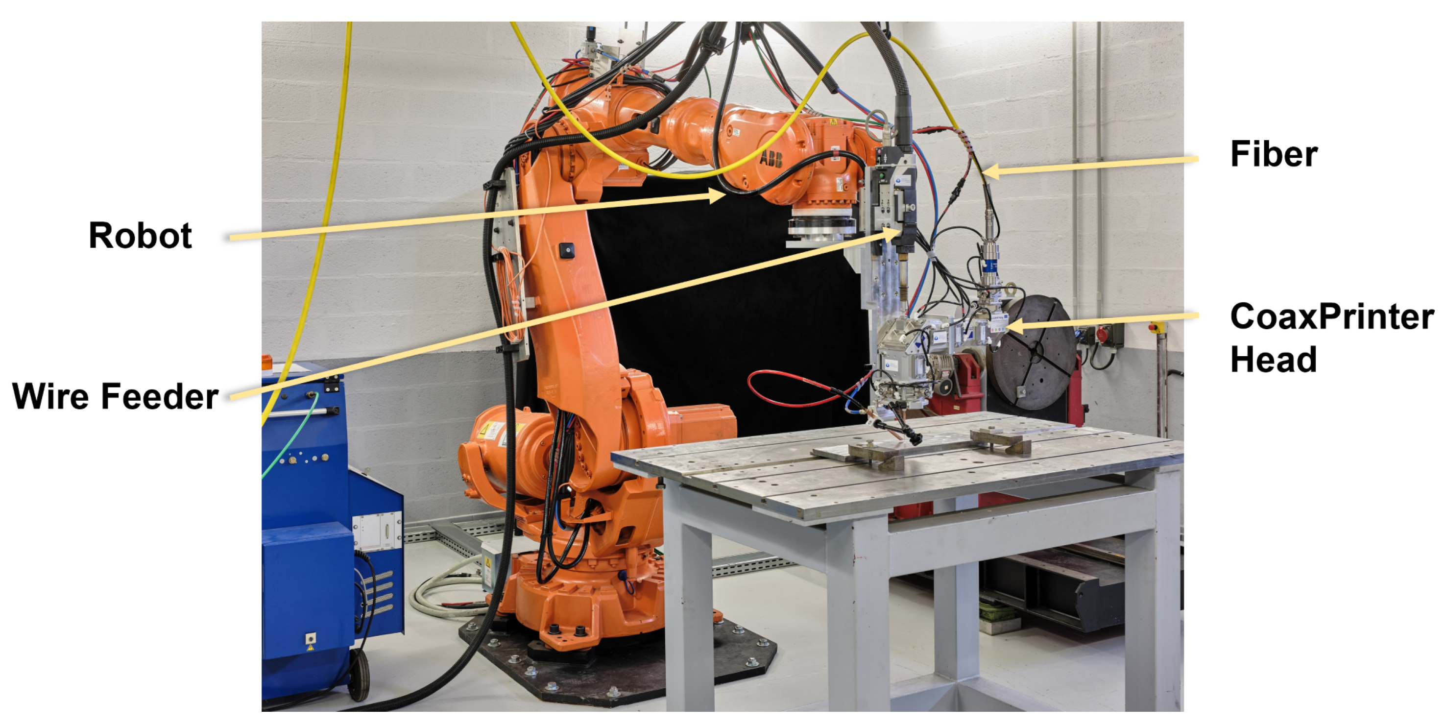
8]. With regard to the additive material form, Laser Additive Manufacturing could be divided into powder-based and wire-based Laser Additive Manufacturing. In this paper, we will focus on the Laser Wire Additive Manufacturing (LWAM) technology.
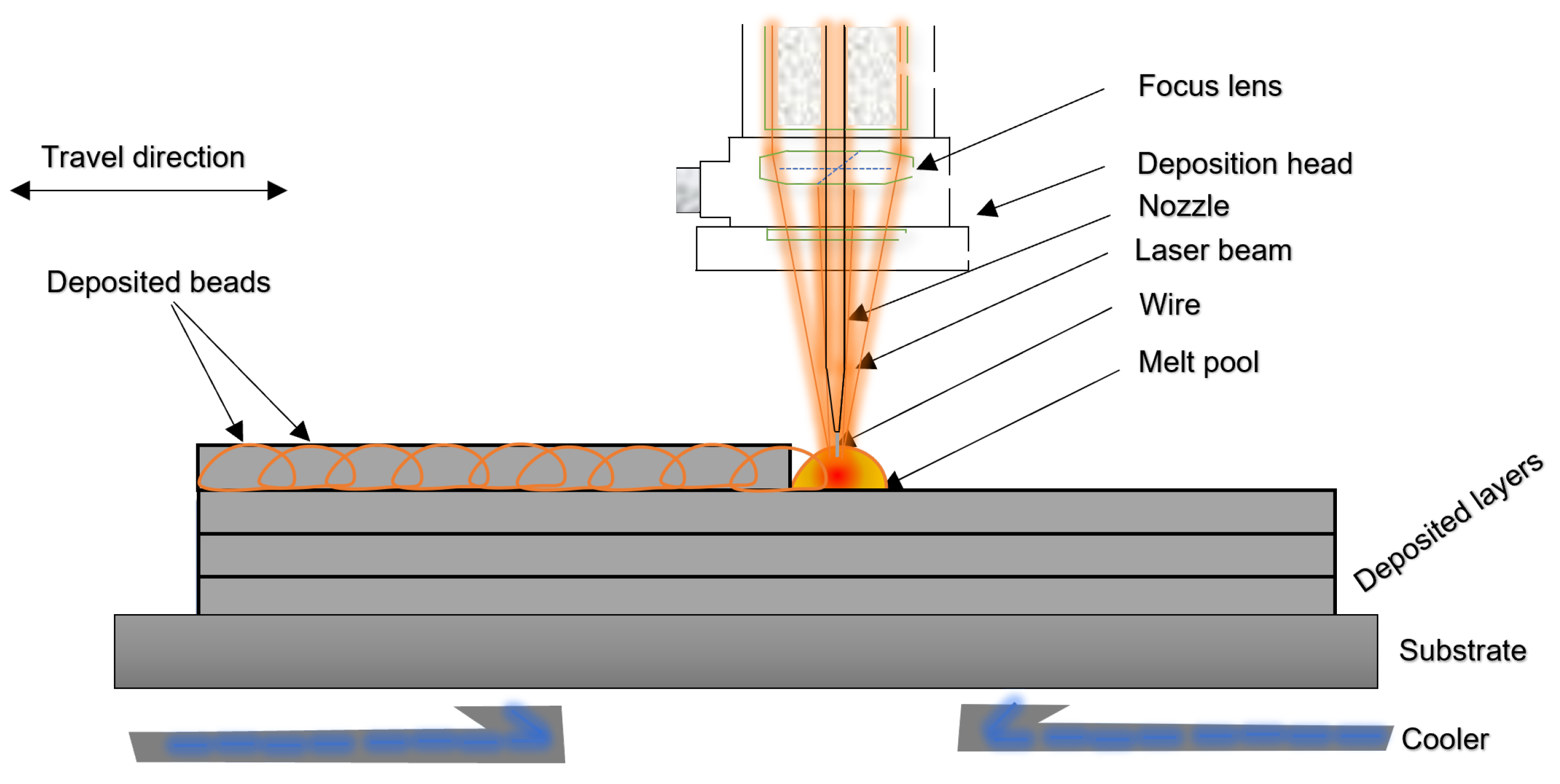
The process of LWAM consists of melting a wire using an energy source to create a liquid melt pool bead. The beads are then added layer by layer to form the final object, as illustrated in
Figure 1.
To obtain a stable deposition process, reliable sensing, modeling and control approaches are needed. In Mbodj et al. [
9], a model to predict bead geometry and improve deposition accuracy was proposed. More specifically, a regression algorithm is applied to fit bead geometry with the main deposition process parameters (laser power, wire feed rate and advanced speed) and a neural network-based approach was used to study the influence of the parameters on the bead geometry. Magerramova et al. [
10] investigated body parts using computational and experimental methods. The Finite Element Method (FEM) was used in the Laser-Based Manufacturing (LBM) process to simulate gearbox housings and numerically optimize the product weight. The results show that the mass of body parts is reduced by up to 15% with the same strength properties. Finally, Liu et al. [
11] used a 3D microscale FEM with a powder arrangement system to simulate multi-layer powder stacking for Selective Laser Sintering (SLS). The model aimed mainly to investigate the thermal evolution of selective laser sintering using metal powders.
Furthermore, Fetni et al. [
12], developed an empirical model to study the impact of process parameters on the deposition. The thermal history and the melt pool dimension evolution of a 316L stainless steel reinforced by Tungsten carbides were studied using finite elements. The experimental analysis was correlated with the numerical results using experimental observations from light optical, scanning electron microscopies and thermocouple records. Corbin et al. [
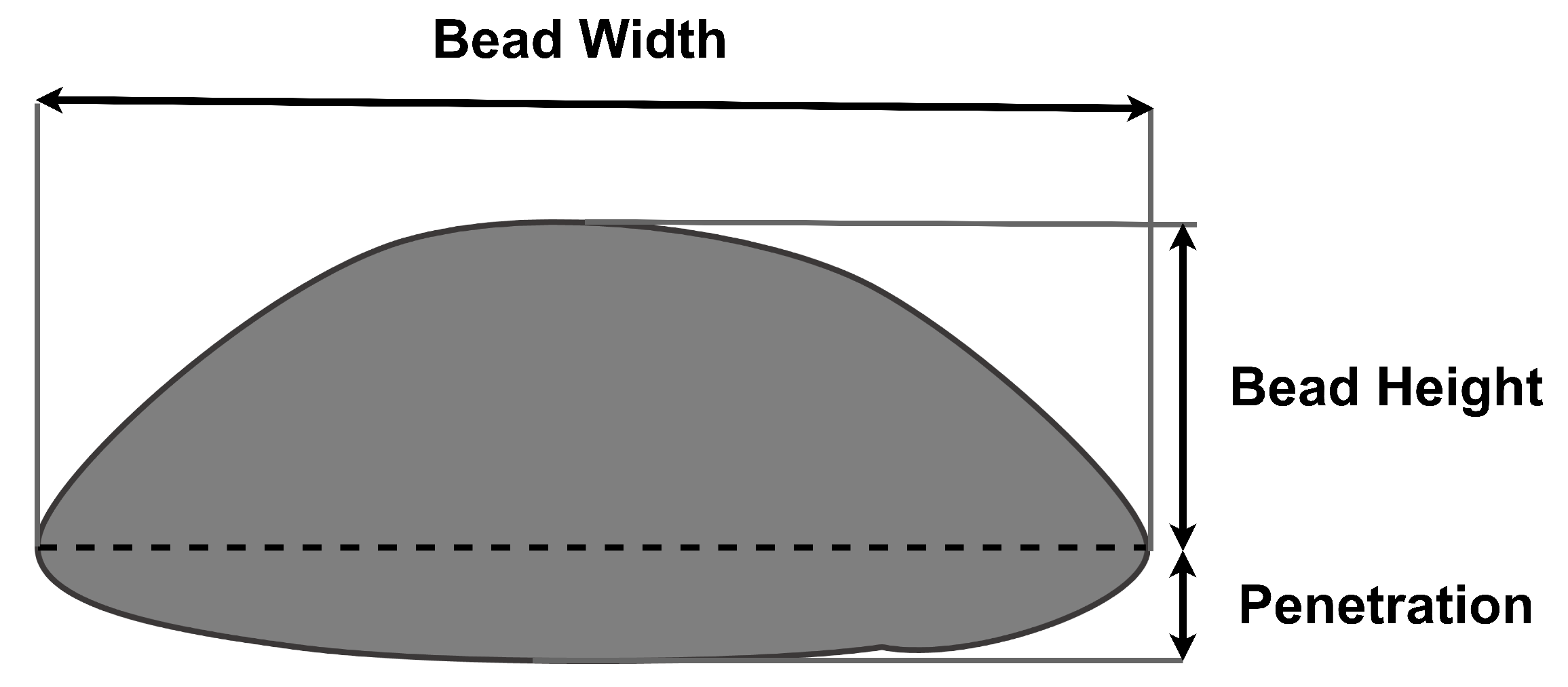
13], proposed an empirical model of single bead geometry and the process parameters was developed. Linear regression was applied to fit the collected data using an optical profilometer. The response variables are the bead height, bead width, and angle of repose. The model showed the influence of the process parameter’s interaction on the bead geometry. Kiran et al. [
14] developed a thermo-mechanical weld model for 316L stainless steel. Their model estimates the residual stress for large parts. The results obtained are compared with the experimentally measured thermal field to validate the approach. On the other hand, Gockel et al. [
15] created a process map of single beads of Ti-6Al-4V using finite element analysis. The process is developed for the microstructure solidification in electron beam wire feed AM processes.
The presented computational methods, for developing a physical model of the bead deposition, are limited and complicated to be employed from the control system design point of view. Therefore, an analytical model is suggested for process optimization as well as for designing a stable and fast controller. The first analytical model for metal deposition was developed in 2001 by Doumanidis et al. [
16]. The analytical model includes the material transfer phenomena and thermal transfer of the moving source. The model was derived from the molten pool’s scalar mass, momentum, thermal conduction, and energy balances. Years later, Wang et al. [
17] proposed an improved model based on Doumanidis et al.’s work. The developed physics-multivariable model proposed a parameterization of the material transfer rate as a function of the process parameters, thus characterizing the steady-state melt-pool geometry. Yuze et al. [
18] proposed an analytical method to predict the clad geometry and the catchment efficiency. The model couples the moving laser beam, the powder stream, the semi-infinite substrate with the heated powder spatial distribution, the attenuated laser power distribution, and the 3D shape of the melt pool. Furthermore, Yuze et al. [
19] developed a physics-based model for melt pool dimensions, height, width, and wetting angle. The model was applied on single-track to multi-track and multi-layer deposition. The experimental validation showed good agreement at different levels of specific energy and powder feed rate for single-track simulation and good prediction of the dynamic height for 3D profile structures. However, some discrepancies between the model prediction and the experimental results were noticed. The differences came from the deviation of the powder feeding and the heat convection leading to oxidation in the process.
Regarding the monitoring systems and controller design in the M-AM, Farshidianfar et al. [
20] developed an infrared system to monitor surface temperatures of deposition microstructure during Laser Additive Manufacturing (LAM). A PID feedback controller stabilizes the cooling rate by adjusting the travel speed. The experimental results show that the controller can achieve acceptable microstructure in real-time. In the work of Garmendia et al. [
21], a structured light scanner is used to obtain the part height. A closed-loop controller is implemented to adjust the deposition height to ensure a good geometrical accuracy of the final part. The results show that the model can give satisfactory results both on power and wire-based laser metal deposition (LMD). Heralic et al. [
22] used a 3D scanning system to obtain the surface for each deposited layer. An iterative learning control system compensates for the depositions by varying the wire feed rate across layers. The experimental results showed that the developed model works for the automatic deposition of structures. Gibson et al. [
23] presented multiple modes of closed-loop melt pool size control in laser-wire based DED. A real-time closed-loop melt pool size control through laser power modulation and a controller that modulates the print speed and deposition rate on a per-layer basis was developed and demonstrated. In [
24], Liu et al. used a near-infrared monochrome (NIRM) camera to get the melt pool size and a first-order transfer function created for an automatic control system. The laser power was used as the input variable in the system and a Model Predictive Controller was created to control the melt pool size. The experimental results showed that the control system had improved the final part quality. Xiong et al. [
25] created a single-neuron self-adjusting controller for the wire and arc additive manufacturing (WAAM) process. The controller takes the travel speed as the input to correct the layer width. The experimental results show that the controller contributes to the stability of the layer width. In [
26], the clad height is controlled using the scanning speed as the control input. A charge-coupled camera gets the training data profiles and Adaptive Neuro-Fuzzy Inference Systems (ANFIS) is developed to control the system. The experimental results showed satisfactory outcomes in the laser cladding process. Finally, Zeinali et al. [
27] presented a real-time acquisition and control of the clad height. The substrate velocity is taken as the input of the system. A camera is used to obtain the clad height and an adaptive sliding mode control with an uncertainty estimator is implemented. The experimental results showed an improvement in the final deposition.
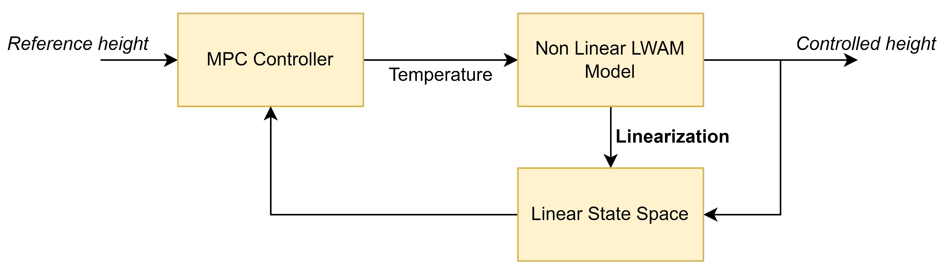
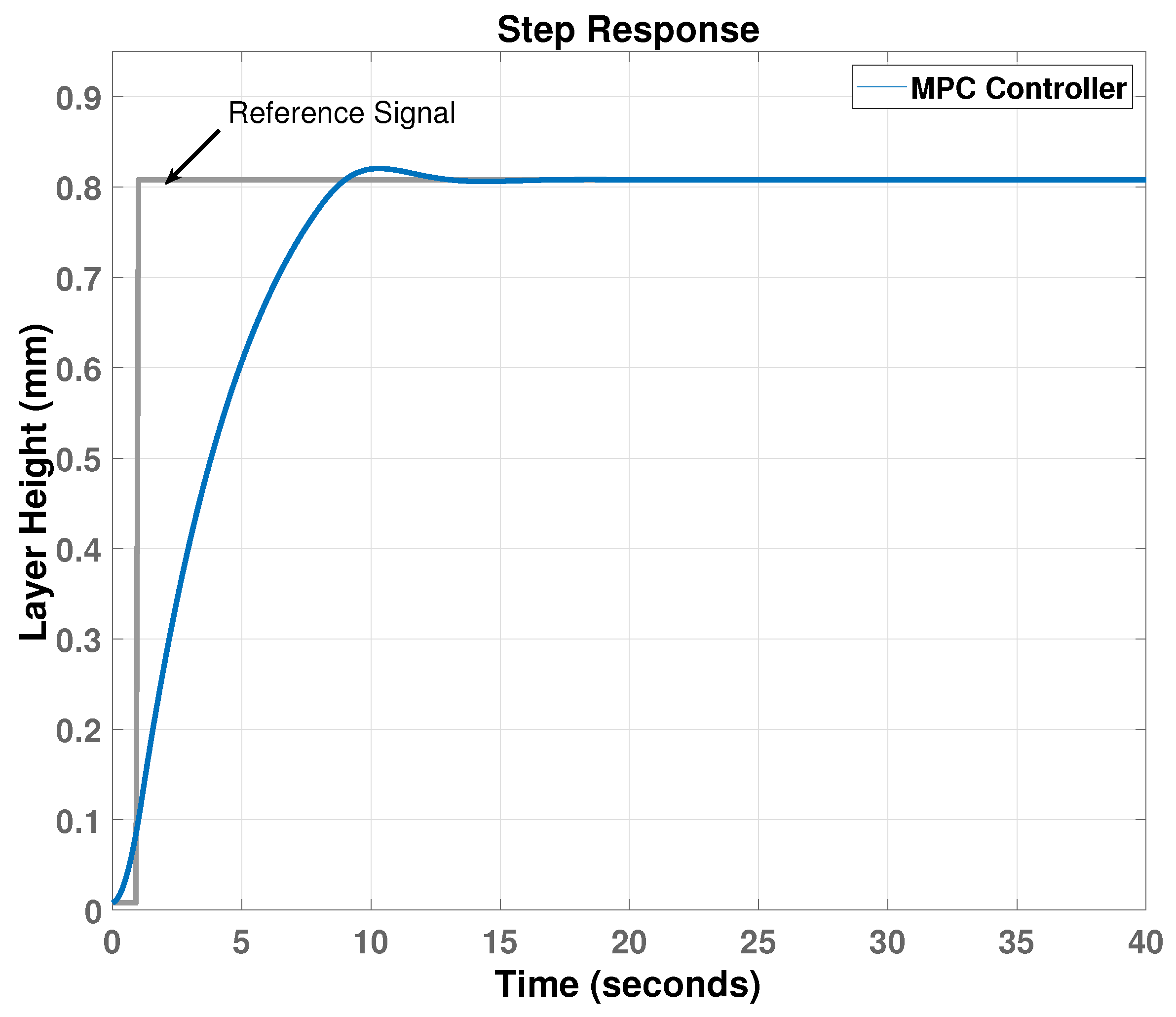
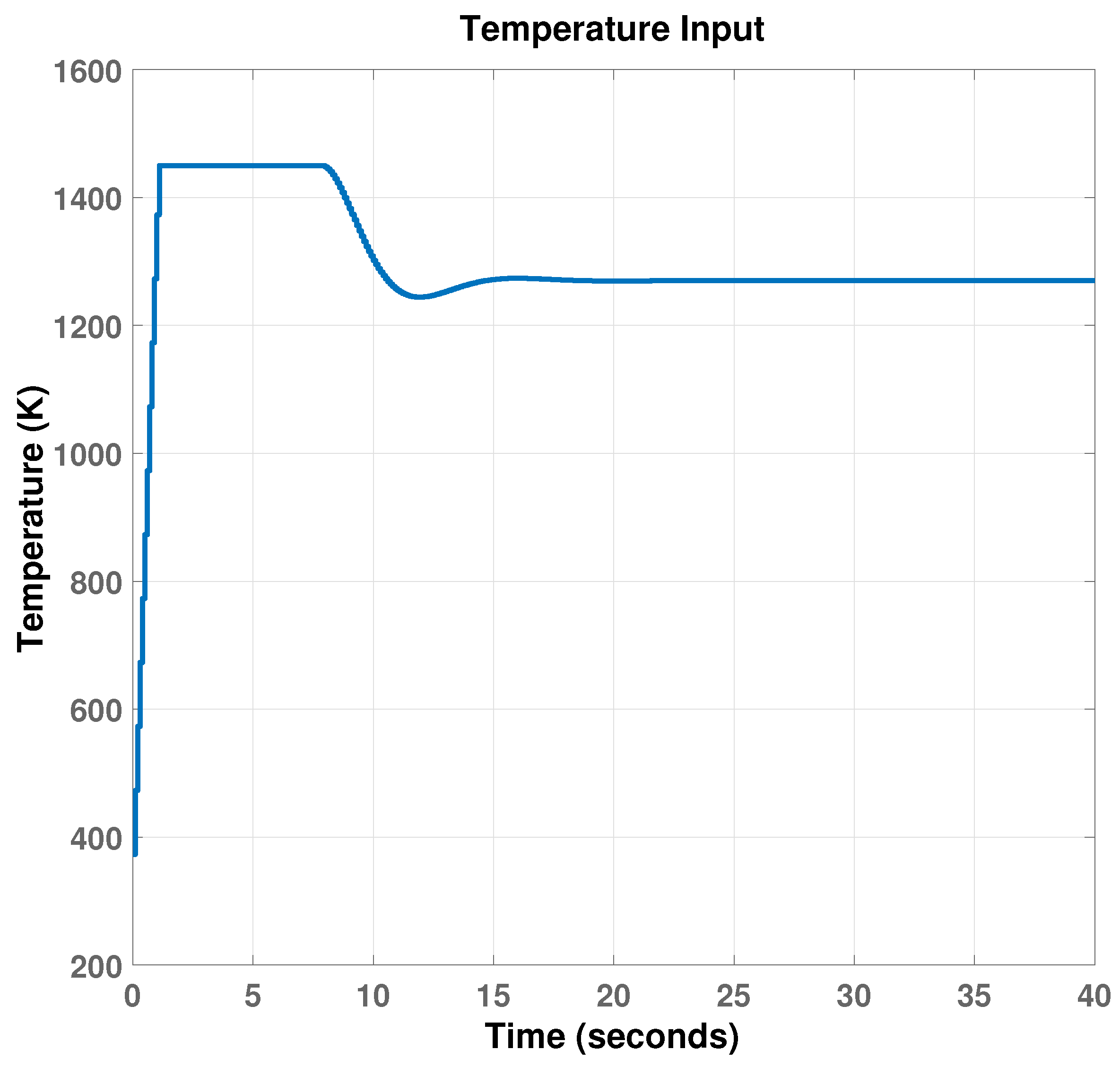
Based on the cited works, physical model implementation and control design for the LWAM process has not been developed in detail due to system complexity and parameter diversity. Therefore, the aim of this work is to derive a physics-based multi-variable model that describes the LWAM process and to design a Model Predictive Controller (MPC) based on the derived model. More specifically, the proposed model describes the relationship between the layer height and the molten pool behaviour, material properties, process parameters, and thermal history. The proposed model provides easiness and computation efficiency for offline simulation when dealing with process parameters and designing a layer height controller for LWAM. Thus, the main contributions of this work are, (i) proposing a dynamical model description of layer height deposition in the LWAM by taking into account different process parameters and material properties; (ii) designing an MPC to control the layer height to achieve good deposition and improving the quality of the final printed part in the LWAM process.
The rest of this paper is structured as follows,
Section 2 and
Section 3 provide a detailed theoretical background for the numerical model implementation and MPC design for the LWAM process respectively.
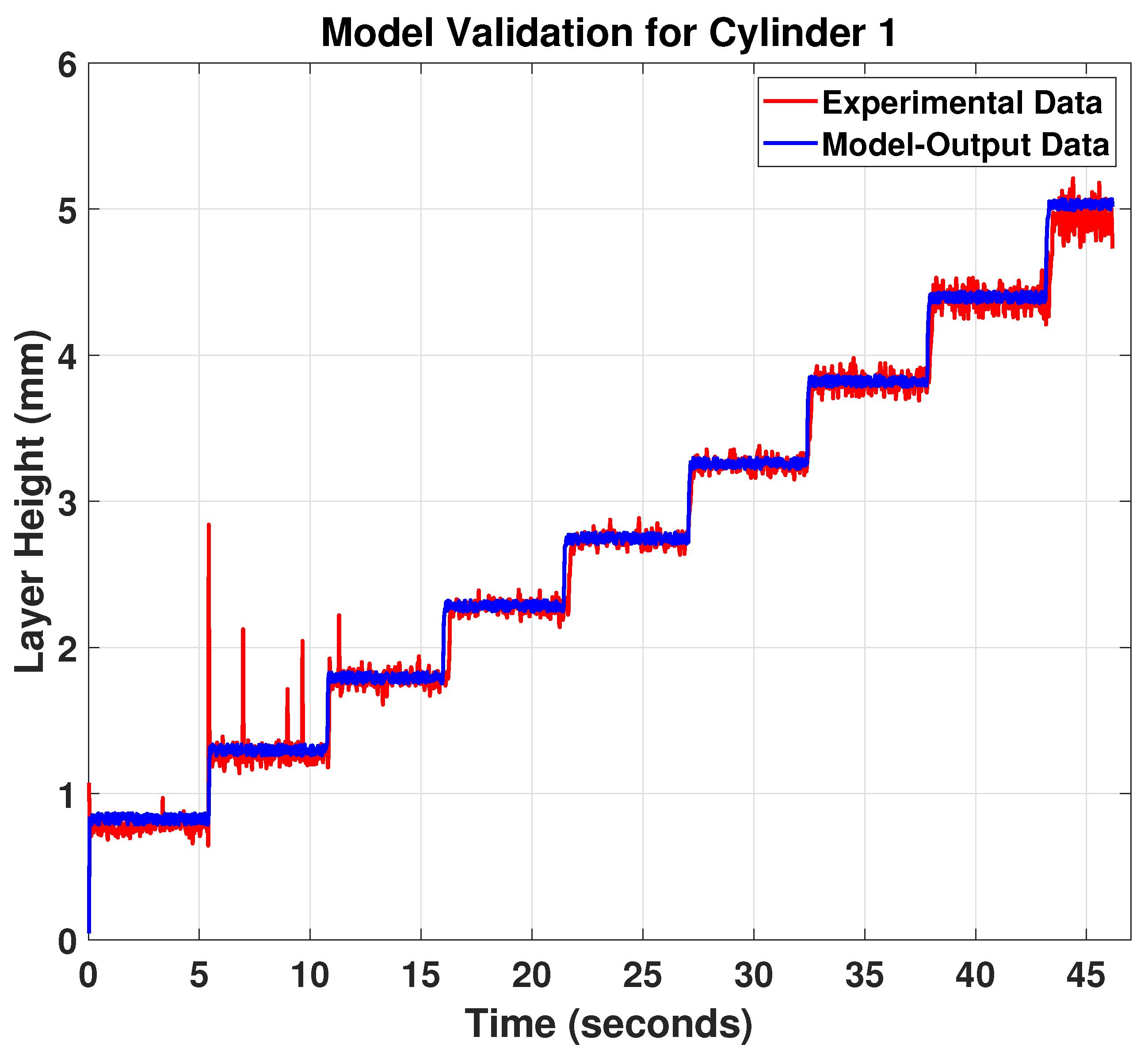
Section 4 presents the simulation and experimental results and discussion. The paper finishes in
Section 5 with conclusions.
2. Numerical Model
As a non-linear process, LWAM involves complex interaction to perform a material transfer using wire and laser power. The main process parameters interfering in the process are the laser power, the travel speed, the standoff distance, and the wire feed rate. Some insights based on previous studies (e.g., [
16,
28,
29]) and the authors’ knowledge of the LWAM process are used to develop the desired model. The proposed model provides a physical description of the LWAM process, considering most of the process requirements. This model can also be considered as a pillar for a reliable controller design.
Based on Doumanidis et al. [
16], the mass change rate of the melt pool is equal to the material transfer rate minus the mass rate of solidification (material loss), and it is given by,
where
is the melt pool density,
V is the volume of the melt pool,
is the mass transfer efficiency,
is the total material transfer rate (wire feed rate),
A is the cross-section area of the melt pool and
v is the travel speed. The mass transfer efficiency of the deposition is the ratio of the mass deposited over layers with respect to the consumed wire. Equation (
1) was derived based on the approximation of the bead geometry profile to have a half-ellipsoidal form, as shown in
Figure 2.
The half of the three-dimensional ellipsoid is characterized by the melt pool width,
w, the melt pool length,
l, and the melt pool height,
h. Therefore, the volume
V can be expressed with respect to the melt pool geometry variables (
w,
h and
l) such as,
and the area
A is described as,
Further, for simplicity, the ratio between the melt-pool width and height will be fixed. Also, the melt-pool width and length are assumed to be equal in the derivation of the equations; in this work, some deposition trials allowed to obtain this ratio for different process parameters, as presented in [
9].
It is worth mentioning that, the equation presented by Doumanidis et al. [
16] was derived for the gas metal arc welding (GMAW). Thus, a modification is required to reflect and describe the LWAM process properly. Therefore, after substituting the volume, the area, and the the width-length ratio, the mass conservation equation of the melt-pool in the LWAM becomes,
The derivative of
with respect to the melt-pool height variable, assuming that
l =
w and the ratio
(see e.g., [
28]), is given by the following equation,
Then, the mass balance equation of the melt pool can be rewritten as,
In Equation (
6), the obtained model does not explicitly show how the model uses the laser power. Also, several process parameters and material properties should be taken into account in the model equation to understand the physics of the deposition process. Therefore, Equation (
6) needs to be extended to an equation that relates the melt-pool dimension to the process parameters and material properties. Eagar and Tsai [
29] developed a mathematical equation expressing a Gaussian heat distribution of the melt-pool where the pool shape was represented as a function of the operating parameter, and it is given by,
where
Q is the laser power,
a is the thermal diffusivity,
C is the specific heat,
is the melting temperature and
T is the initial temperature of each layer. To extend Equation (
7) to the bead geometry profile, Wang et al. [
17] proposed a parametrization of the melt pool cross-sectional area at a steady state to the operating process parameters
, such as,
where
is a general linear function. Wang expressed the melt pool cross-sectional area at a steady state as,
Following this idea, this work adopts the same assumption for the cross-sectional area in the LWAM and assumes the existence of a linear coefficient called
. From this assumption, Wang’s parametrization, shown in Equation (
8), becomes,
From Equation (
10), the cross-sectional area
A is derived as,
From Equation (
11), it is evident that the melt-pool area varies with the increase or decrease of the laser power, and it also varies with the variation of the velocity. Considering the melt pool’s balance Equation (
1) at steady-state conditions,
=
−
Av = 0, gives
=
Av. This means that the material transfer rate is equal to the mass rate of solidification at a steady state. Then the material transfer rate,
can be approximated to the mass rate of solidification. Therefore, the following equation can be drawn,
and thus the material transfer rate from Equation (
12) is equaled to Equation (
11), such as,
Therefore, the mass balance equation becomes,
The obtained Equation (
14) can be further extended. The extension can be possible with Pinkerton et al.’s works [
30]. Pinkerton stated that the heat flowing into the melt pool is determined by considering the interaction between laser parameters and the melt pool. Pinkerton et al. expression has used the optics parameters and the power variation with respect to the z-axis to describe the system. It assumes the laser beam has an even power distribution for calculating the intensity of radiation that reaches the melt pool. The equation states that the diameter of the laser beam in a horizontal plane through the deposition point,
d, is given in terms of the melt pool standoff,
, the beam diameter
D, and the focal length of the objective lens
f, and it is given by,
Further, Pinkerton investigated the relationship between the intensity and other variables. Pinkerton developed another equation that relates the intensity of the laser source
I to other process parameters and material properties around the beam area at the melt pool, such as,
where
Q is the laser power and
is the proportion of laser power reflected from the wire. Also, Pinkerton assumed that the heat flowing into the melt pool is proportional to the intensity of the laser source
I, the melt pool width
w and the melt pool’s surface absorptivity
. Therefore, the rate of heat flowing into the melt pool is expressed as,
Based on Pinkerton’s equations, it is now assumed that in the LWAM process, the heat flowing into the melt pool can be expressed as,
where
is the absorptivity of the melt pool,
f is the focal length,
w the width of the deposited bead,
is the reflected laser power from the wire,
D is the beam diameter of the laser source and
is the standoff distance.
In LWAM, the standoff distance (
) is not stated forward and well defined as in other processes, this variable will be set up, in this work, in the following manner. The
is defined with respect to
, which is called the working distance. In this work, we assume that
, as shown in
Figure 3, where
is the nozzle variable that describes by the movement of the nozzle on the Z-axis.
In order to extend the Equation (
19) to include more process parameters and material properties, the Rosenthal equation is used in the LWAM process [
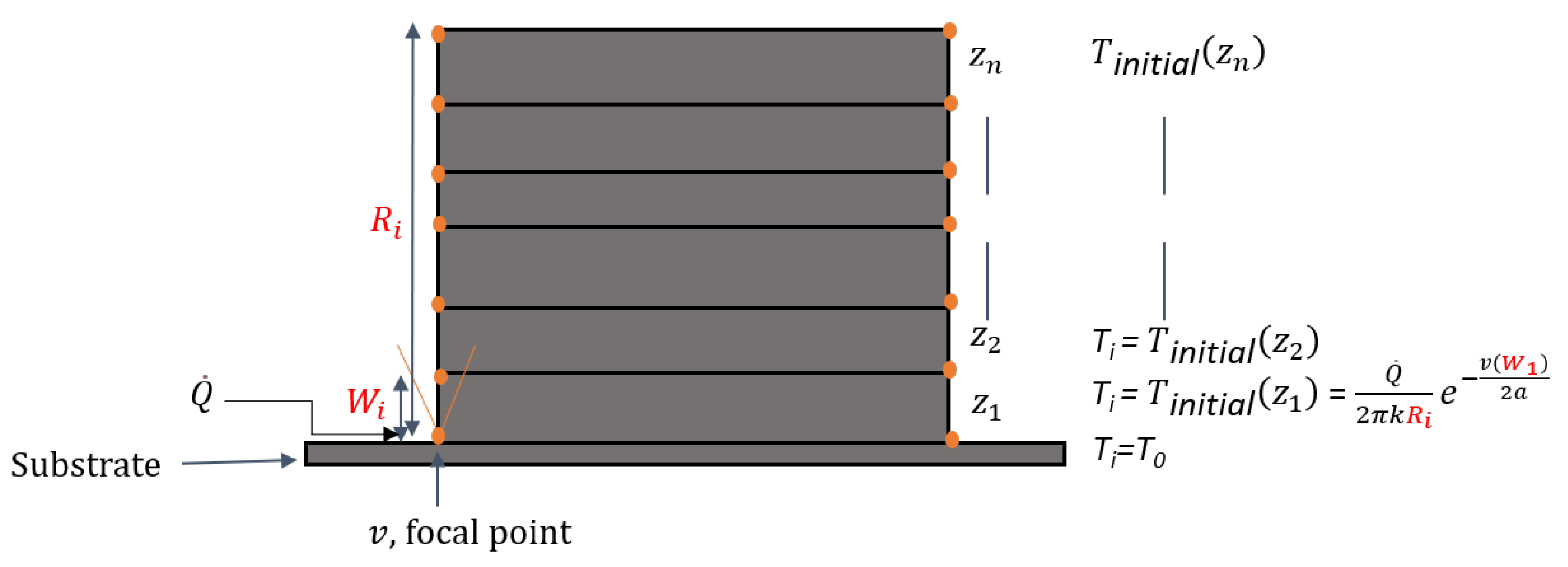
31]. It is assumed that the heat flowing into the melt pool moves from layer to layer during the deposition process. The application of Rosenthal’s equation at each layer edge is assumed to be,
where
is the initial temperature at layer
,
is the temperature of the preceding layer with
to
n;
n is the last layer,
k is the thermal conductivity,
is the length of the part,
is the theoretical layer thickness,
v is the scan speed and
a is the thermal diffusivity, as shown in
Figure 4.
Substituting Equation (
18) into Equation (
19) will change the temperature distribution at each layer edge (the orange points in
Figure 4) while including more process variables (
,
f,
D,
v) and more material properties (
,
k,
a ) to the LWAM process for a fair physical description of the process, as described by,
Finally, the mass balance equation from Doumanidis (
1) becomes an extended dynamics multivariable equation applied to the LWAM process, given by,
Equation (
21) calculates the melt pool height for the LWAM process while taking into consideration several process variables and material properties involved in the complex process. This equation includes several variables that can be used for simulation purposes to understand their influence on bead geometry. Further, this equation can be used in control system design to regulate one or more deposition process parameters, as will be discussed in
Section 3.


 ,
, 


