Article

Evaluation of the Cathodic Electrodeposition Effectiveness of the Hydroxyapatite Layer Used in Surface Modification of Ti6Al4V-Based Biomaterials

by
Michalina Ehlert
1,2,*,
Aleksandra Radtke
1,2,
Michał Bartmański
3 and
Piotr Piszczek
1,2,*
1
Department of Inorganic and Coordination Chemistry, Faculty of Chemistry, Nicolaus Copernicus University in Toruń, Gagarina 7, 87-100 Toruń, Poland
2
Nano-Implant Ltd., Gagarina 7/47, 87-100 Toruń, Poland
3
Department of Biomaterials Technology, Faculty of Mechanical Engineering and Ship Technology, Gdańsk University of Technology, Gabriela Narutowicza 11/12, 80-233 Gdańsk, Poland
*
Authors to whom correspondence should be addressed.
Materials 2022, 15(19), 6925; https://doi.org/10.3390/ma15196925
Submission received: 29 August 2022 / Revised: 23 September 2022 / Accepted: 1 October 2022 / Published: 6 October 2022

Abstract

:
The important issue associated with the design and the fabrication of the titanium and titanium alloy implants is the increase of their biointegration with bone tissue. In the presented paper, the research results concerning the conditions used in the cathodic deposition of hydroxyapatite on the surface Ti6Al4V substrates primarily modified by the production of TiO2 nanoporous coatings, TiO2 nanofibers, and titanate coatings, are discussed. Despite excellent biocompatibility with natural bone tissue of materials based on hydroxyapatite (HA), their poor adhesion to the substrate caused the limited use in the implants’ construction. In our works, we have focused on the comparison of the structure, physicochemical, and mechanical properties of coating systems produced at different conditions. For this purpose, scanning electron microscopy images, chemical composition, X-ray diffraction patterns, infrared spectroscopy, wettability, and mechanical properties are analyzed. Our investigations proved that the intermediate titanium oxide coatings presence significantly increases the adhesion between the hydroxyapatite layer and the Ti6Al4V substrate, thus solving the temporary delamination problems of the HA layer.

1. Introduction

Titanium and its alloys are wieldy used as load-bearing implants [1,2,3]. Among them, the Ti6Al4V alloy in particular has been considered as one of the suitable candidates for bioimplants due its good biocompatibility, well-balanced strength-to-weight ratio and comparatively low elastic modulus [4,5,6]. Nevertheless, research is still being conducted to achieve a higher biointegrity of the Ti6Al4V alloy and closer mechanical properties to the skeletal system. It should also be noted that the studies of titanium-based materials used in the construction of modern implants revealed their susceptibility to bacteria-induced inflammations [7,8,9]. It can lead to the loosening of the implants and other complications and consequently, their removal or replacement may be necessary. The surface modification of implants by producing the coatings of defined architecture, which will inhibit the adhesion of bacterial cells to them, is one of the proposed solutions. Electrolytic oxidation (anodizing), allowing for the production of different surface architecture coatings, i.e., nanoporous, nanotubular, or nanosponge-like types, is a widely used method [10,11,12]. Another good example is the result of investigations concerning the Ti6Al4V implant surface modification using SLS technology (selective laser sintering). It was found that Ti6Al4V implant surface modification by the TiO2 nanoporous layer covering, led to the formation of a system of more suitable physicochemical and osseointegration properties [10,11,13]. Moreover, this layer exhibited excellent wear resistance and the ability to propagate energy at plastic deformation during loading. The increase in the antimicrobial activity of this implant was obtained by surface enrichment with metallic silver nanoparticles. A significant advantage of the modification type mentioned above was that the layer did not release substances showing mutagenic properties [14,15].
From the new generation implant construction point of view, the crucial issue is to equip their surface with a biocompatible, bioactive coating layer that adheres perfectly to the substrate (e.g., does not delaminate during use of the implant) [16,17]. The way to achieve this effect can be a production of an additional coating of a bone-like substance that is hydroxyapatite (HA), i.e., hydroxyl-containing forms of calcium phosphate, which promotes bone formation and growth [17,18]. Crystalline HA provides mechanical stability to the coating. However, in the environment of body fluid it can slowly degrade, leading to insufficient bone ingrowth [19]. On the other hand, the amorphous type has a slightly higher solubility, which promotes faster initial bone fixation due to resorption and bioactivity [20]. For biomedical applications, an important ceramic material is a hydroxyapatite with a Ca/P molar ratio of 1.67. Since it can provide the mineral scaffolding for connective tissue, which is responsible for the mechanical strength of bones [16,21]. The use of hydroxyapatite as a protective coating for various metallic implants offers many advantages. The surfaces of metal implants become more resistant to corrosion and are also protected against releasing toxic ions from their surfaces [21]. Furthermore, the production of a hydroxyapatite coating promotes the formation of apatite, the main inorganic component of bone and teeth [22,23,24]. However, calcium phosphate coatings often exhibit poor adhesion to metallic substrates. Implants with an HA layer may undergo fatigue failure in load-bearing applications. According to literature data, it is assumed that in order to avoid fatigue damage and dissolution, the thickness of the HA layer should be ca. 50 μm [22,25].
The plasma spraying, pulsed laser deposition, sol-gel method, PVD (sputter coat-ing), electrophoretic deposition, electrodeposition, and gas detonation deposition are usually used for producing an HA layer on implant surfaces [16,17,21,24,26,27,28]. Plasma spraying is the most popular, which has the advantage of being able to produce highly repeatable coatings. Nevertheless, the plasma spraying process uses high temperatures, often linked to uncontrolled phase changes and thermomechanical mismatches [16,27,29,30]. An alternative method to produce hydroxyapatite layers is electrodeposition. This is an efficient technique for producing a calcium phosphate layer on the surface of a conductive material through a series of chemical reactions in an aqueous solution using electrical energy [16,21,24,27,31]. The electrochemical technique is attractive due to its simplicity, low cost, uniformity of the produced coatings, and ability to precisely control the properties of the layers produced (chemical composition, thickness, structure) at low temperatures. It is suitable for coating surfaces with complex geometries [16,17,21,32]. The major limitation of the electrodeposition technique is the poor adhesion of the HA layer to the implant’s surface [16,21,33]. Usually, the interfacial delamination of the HA layer is initially caused by vertical cracking of the coating throughout the thickness, which occurs at the HA–Ti6Al4V and HA–human bone interface [34]. The delamination of the hydroxyapatite layer can lead to the formation of inflammation in the surrounding organs, and consequently bone loss and even loosening of such an implant [22,35]. The analysis of literature data shows that research on this issue is conducted in various directions. An example is using computational models to the analyze Tresca stresses in metal bearings, as well as to assess delamination-fretting damage [34,36]. According to Ammarullah et al., it is the Ti6Al4V-on-Ti6Al4V bearings that show the superior Tresca stress reduction properties among other metal-on-metal bearings [36].
Nevertheless, so far, research using a connector has not yielded the expected results, so we aimed to produce a group of different connectors and select the most optimal one to create more stable HA layers [22,37]. For this purpose, a multistage chemical treatment of the Ti6Al4V substrate surface was used to create a stable intermediate layer connecting the alloy surface with the hydroxyapatite layer. Based on our earlier works, the following coatings were selected: (a) nanoporous TiO2 coatings, (b) nanofibrous TiO2 coatings, and (c) titanate coatings. It should be noted that we tested the coatings mentioned above as independent systems but not as intermediate ones [10,38,39]. For this reason, an innovative aspect of the presented paper is the system’s production: Ti6Al4V–intermediate layer (TiO2 or titanate)–HA. Titanium oxide coatings show high biointegration properties and better mechanical properties than titanium alloy. However, their Young’s modulus and hardness parameters are still higher than cortical bone’s. Therefore, our research aimed to produce a coating system whose mechanical parameters are like the cortical bone and reveal the hydroxyapatite layer’s high adhesion strength to the Ti6Al4V substrate. To achieve this effect, we optimized the process conditions of the cathodic electrodeposition of hydroxyapatite and the determined mechanical properties of produced systems Ti6Al4V-intermediate layer-HA.

2. Materials and Methods

2.1. The Synthesis of TiO2 and Titanate Nanocoatings

All experiments were carried out using Ti6Al4V alloy (marked as T, grade 5, 99.7% purity) (Strem Chemicals Inc., Bischheim, France), a foil of 0.2 mm thickness, as a base substrate, which was cut into strips of 6 mm wide and 100 mm long. In the first stage, the surface of T substrates was modified by manufacturing TiO2 nanoporous (T5) coatings and TiO2 nanofiber (TNF6 and TNF72), and titanate (T5-S and T-S) types, according to methods previously described (all acronyms used in this article are consistent with those used to mark samples in earlier works) [10,11,38,39,40]. Before the next stages of the research, the samples were structurally and morphologically characterized.
Details of T surface modification:
(a)
The anodic oxidation method allowed the production of T5 coatings on the surface of Ti6Al4V substrates. This method used the 0.3% HF solution as an electrolyte, t = 20 min, and the 5 V potential. The produced T5 coatings were rinsed with deionized water and in acetone for 10 min.
(b)
The TNF coatings were produced due to T sample surface chemical oxidation. The surfaces of the substrates were chemically etched in c.a. 5.8 M HCl. Afterwards, materials were heated in 30% H2O2 solution at 358 K under a reflux condenser (TNF6C) or in an incubator (TNF6S) for t = 6 h. The nanofibrous samples marked TNF72 were produced in a slightly different procedure. The surface etching of the Ti6Al4V substrate was applied (a) in 2M HF solution for 10 s (TNF72a) or (b) in a 1:4:5 mixture of HF:HNO3:H2O (TNF72b). Then, the samples were immersed in 30% H2O2 solution at 358 K for 72 h in an incubator.
(c)
The alkali-sodium treatment produced the T-S and T5-S samples. The Ti6Al4V sample (T) and nonporous one (T5) were immersed in a 7 M NaOH solution at 339 K for t = 48 h. In the next step, these materials were washed with distilled water and dried at 314 K for 24 h in an incubator.

2.2. Synthesis of Hydroxyapatite on TiO2 and Titanate Nanocoatings

The electrochemical cathodic deposition method was applied when depositing the hydroxyapatite (HA) coating. The experimental set-up is home-made and was made by the authors of this paper. It consists of a laboratory power supply (China, MCP lab electronics, M10-QS1005; display accuracy is ± 0.5%Rdg + 2digits) and two digital multimeters (Germany, Beha Amprobe, AM-510-EUR; accuracy of DC current measurement is ± 1%Rdg + 2digits; accuracy of DC voltage measurement is ± 1%Rdg + 3digits). The deposition process was carried out at 339 K temperature using prepared substrate ((T (Ti6Al4V), TiO2 nanoporous (T5), titanate (T5-S, T-S), and TiO2 nanofibres (TNF6C, TNF6S, TNF72a, and TNF72b)) as cathode, platinum wire as anode (Figure 1). The electrolyte consisted of Ca(NO3)2 · 4 H2O (0.042 M), NH4H2PO4 (0.025 M), and EDTA-2Na (1.5 × 10⁻³ M) in distilled water. The initial pH value of the electrolytes was adjusted to 4.5 using Tris(hydroxymethyl)aminomethane. The deposition process time was 60 min. The electrochemical deposition of HA on each sample was carried out at three different current values, i.e., 1.5 mA, 2.5 mA, and 3.5 mA. The voltage range during deposition was 2.24−3.00 V. After cathodic deposition, specimens were immersed in 0.1M NaOH solution for 2 h at 339 K and then sintered at 524 K for 2 h. All samples prepared for analyses were autoclaved using an IS YESON YS-18L (Yeson, Ningbo, China) at 396 K, p = 120 kPa, t = 20 min.

2.3. Structural and Morphological Characterization

The surface morphology of all samples was studied using a Quanta scanning electron microscope with field emission (SEM, Quanta 3D FEG, Huston, TX, USA). The phase identification of all produced layers was carried out with X-ray diffraction (XRD; PANalytical X’Pert Pro, PANalytical B.V., Almelo, the Netherlands; MPD X-ray diffractometer using Cu-K alfa radiation, grazing incidence angle mode–GIXRD; the incidence angle was equal to 1 degree). Diffuse reflectance infrared Fourier transform spectra (DRIFT, Spectrum 2000, PerkinElmer Inc., Waltham, MA, USA) were used to estimate the structure of the specimens. The chemical composition of all synthesized layers was determined using an energy-dispersive X-ray spectrometer (EDS, Quantax 200 XFlash 4010, Bruker AXS, Karlsruhe, Germany). Surface roughness were carried out using a commercial Nanoscope IIIa MultiMode AFM (Veeco Metrology Inc., Santa Barbara, CA, USA) through the technique of tapping mode, an area of 10 × 10 × 2.5 µm. All analyses were conducted for five samples of each modification.

2.4. Contact Angle

The contact angle of water on all samples produced at different currents was measured at room temperature using a goniometer (DSA 10 Krüss GmbH, Hamburg, Germany) with drop shape analysis software (ADVANCE, Krüss software, Krüss GmbH, Hamburg, Germany). The volume of the deionized water drop in the contact angle measurement was 3 mL for onto each sample. The contact angle was measured in triplicate and the mean value was calculated.

2.5. Nanomechanical Properties and Adhesion

The nanomechanical properties, hardness, and Young’s modulus were studied using the nanoindentation technique with Oliver–Pharr procedure with nanoindenter (NanoTest Vantage, Wrexham, United Kingdom) and Berkovich indenter. The 25 independent indentations were performed on all tested materials on three samples of each group (n = 3). The increased to maximum load was 50 mN and the time was 10 s, with 5 s dwell with maximum load and unloading to zero force equal to 10 s. After indentation, a temperature drift was performed at a load of 5 mN for 30 s. The distance between indentations was 20 µm on both axes. To convert the reduced Young’s modulus for Young’s modulus, according to the Oliver–Pharr procedure, the Poisson’s modification ratio of 0.28 was used. The adhesion of modifications to titanium substrate was studied with a nanoscratch-test. The nanoscratch-test was performed using a nanoindenter (NanoTest Vantage, Wrexham, The United Kingdom) and a diamond indenter. Ten measurements on three samples of each group (n = 3) were made for each sample tested with a maximum force of 500 mN and over a length of 500 µm. The distance between measurements was 250 µm. The adhesion force of the modification to the titanium substrate was evaluated as a sudden and abrupt change in the plot of the normal force against the friction force recorded during the measurement.

3. Results

3.1. Structural and Morphological Characterization of TiO2 and Titanate Nanocoatings

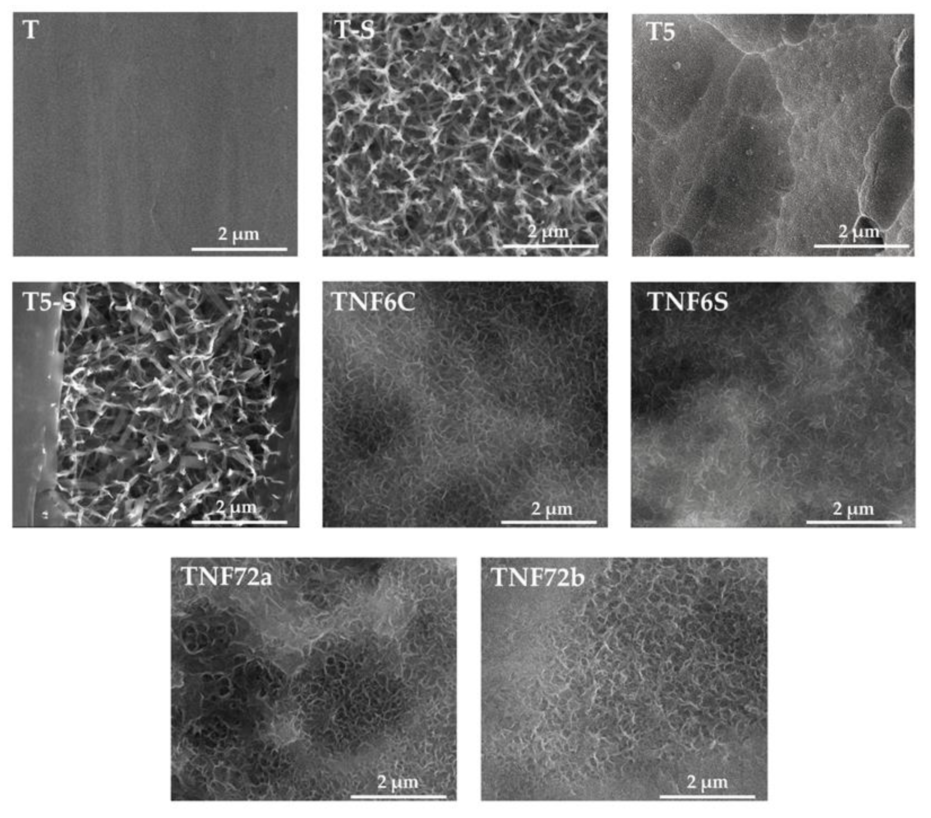
In order to improve the physicochemical properties of Ti6Al4V samples (T), their surface was modified by the production of TiO2-based coatings, which showed suitable mechanical and physicochemical parameters and high biointegration activity using the previously described methods [10,11,38,39,40]. The morphological differences between T, T-S, T5, T5-S, TNF6C, TNF6S, TNF72a, and TNF72b samples are presented in Figure 2.
Searching for the most optimal and repeatable HA synthesis procedure, which can be applied to biomaterials with different nanoarchitectures, our research started by determining such parameters of cathodic deposition as temperature (T) and process time (t) and the effect of EDTA-2Na addition to the electrolyte. In the carried out experiments, the T was changed between 339 and 364 K, t = 25 − 60 min and we tested the use of the electrolyte solution with and without the addition of 1.5 × 10⁻³ M EDTA-2Na. The results revealed that the following conditions were the best—electrolyte containing the EDTA-2Na, T = 339 K, and t = 60 min.
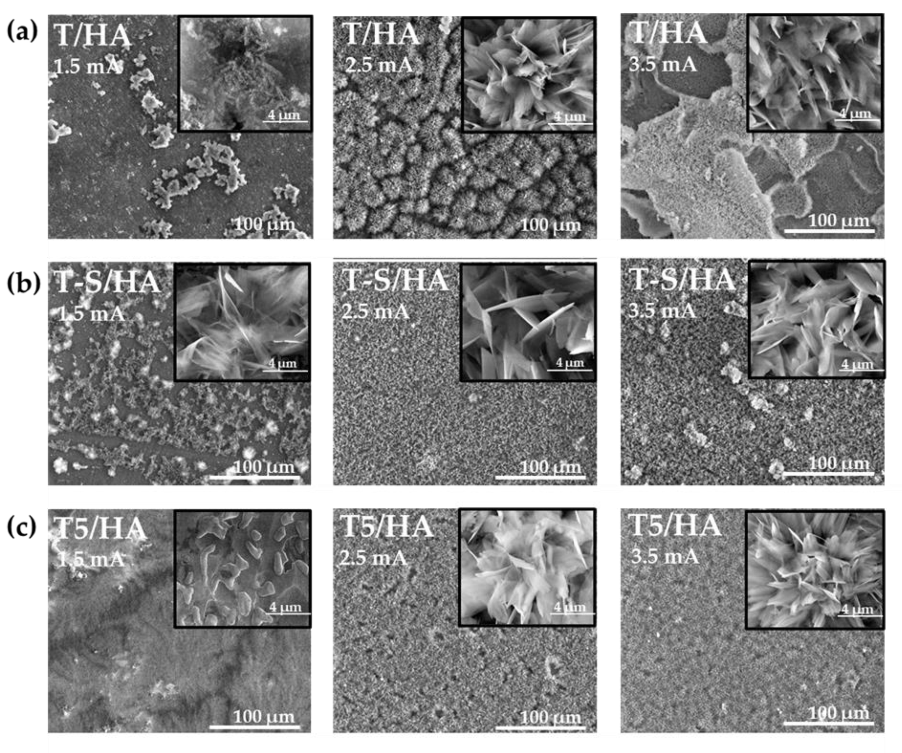
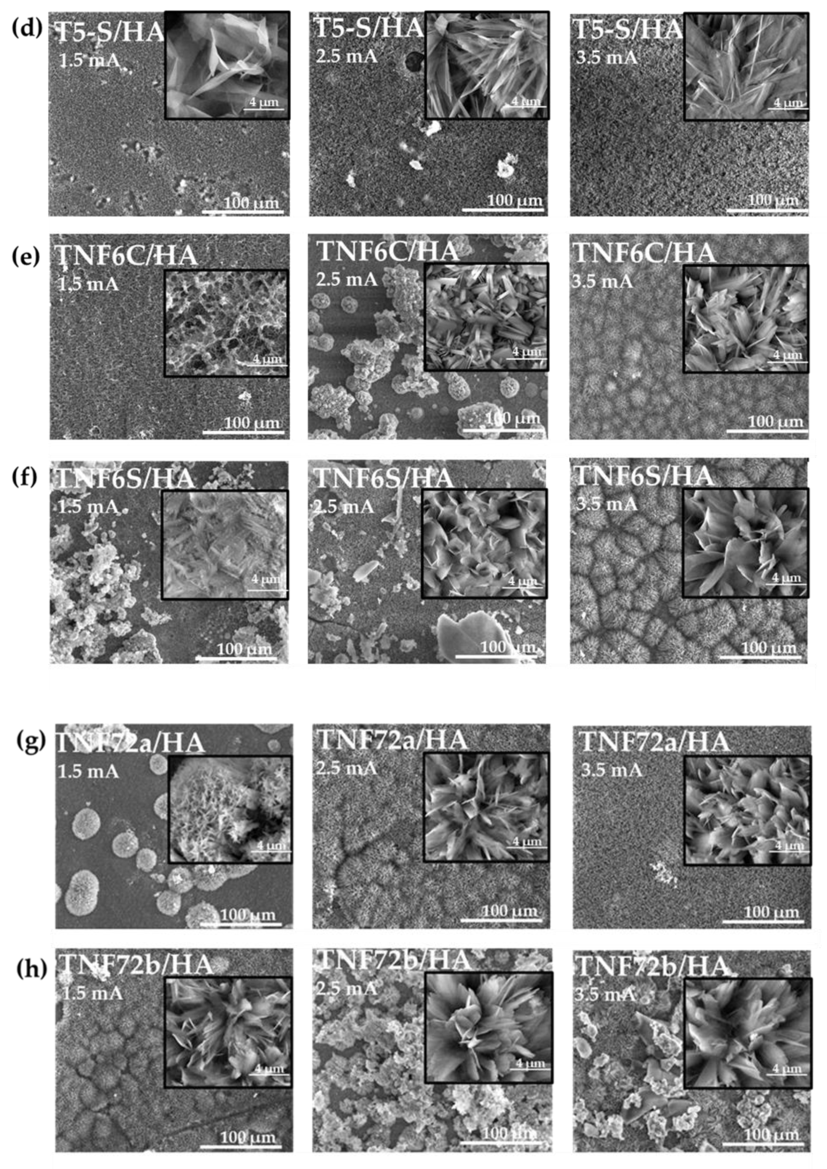
The differences in surface morphology of samples T/HA (a), T-S/HA (b), T5/HA (c), T5-S/HA (d), TNF6C/HA (e), TNF6S/HA (f), TNF72a/HA (g), and TNF72b/HA (h), which were produced at various currents (1.5 mA; 2.5 mA; 3.5 mA) are presented in Figure 3. The morphology and packing density of hydroxyapatite layers significantly depended on the type of substrate and on the current density applied during cathodic deposition. For T/HA, T5/HA, TNF6C/HA, and TNF6S/HA substrates, the applied current of 1.5 mA was too low, and the dispersed HA nucleations of different morphology were formed (Figure 3a,c,e,f)). In the case of T-S/HA, T5-S/HA, TNF72b/HA samples, the hydroxyapatite was formed in the shape of nanoplates (Figure 3b,d,h), while for TNF72a/HA, a floral morphology composed of thin nanoplates was formed (Figure 3g). By increasing the current intensity and thus the current density for all substrates, the hydroxyapatite morphology changed to a floral morphology composed of numerous nanoplatelets. Furthermore, with increasing current density, there is a change in the hydroxyapatite structure from dispersed to densely packed (Figure 3a–h). The further enhancement of the current density up to 3.5 mA led to the delamination of the hydroxyapatite layer deposited on the surface of nonmodified Ti6Al4V substrates (T/HA, Figure 3a). According to literature reports, the intensity of hydrogen gas escaping in the cathodic reaction increases with increasing current density, which can lead to cracks in the hydroxyapatite layer [33,34]. Figures S1 and S2 show SEM cross-section images of the T/HA (a), T-S/HA (b), T5/HA (c), T5-S/HA (d), TNF6C/HA (e), TNF6S/HA (f), TNF72a/HA (g), and TNF72b/HA (h) samples at 2.5 mA current (Figure S1) or 3.5 mA current (Figure S2). By increasing the current intensity, we observe the formation of thicker hydroxyapatite layers on the surface of all the analyzed biomaterials. The most significant growth of the HA layer was noted for T-S/HA (from ~12.58 µm to ~17.60 µm) and TNF72b (from ~14.51 µm to ~20.80 µm) samples (Figures S1 and S2).
Scanning electron microscopy with energy-dispersive spectroscopy (SEM/EDS) analysis revealed mainly calcium, phosphorous, titanium, vanadium, aluminium, and oxygen to be present in the surface of all biomaterials. Small amounts of sodium were additionally detected on the alkali-modified surfaces (T-S/HA and T5-S/HA). The Ca/P molar ratios for the samples with hydroxyapatite layers at different currents are shown in Table 1. A smaller Ca/P ratio for samples T5/HA (0.82) and TNF6C/HA (1.13) at 1.5 mA may indicate the formation of a calcium-poor layer. On the surface of titanium alloy T, nanoporous T5, as well as after alkali-sodium treatment of T-S and T5-S, the most similar Ca/P ratio calculated directly from the EDS results to stoichiometric hydroxyapatite Ca/P ratio (1.67) was obtained during hydroxyapatite deposition at 2.5 mA [16,21,24,26]. In contrast, for TNF6 and TNF72 nanofibrous coatings, the Ca/P ratio is relatively close to the theoretical value during HA deposition at 3.5 mA. SEM/EDS analysis confirmed the presence of hydroxyapatite on titanium oxide surfaces (Figure S3).
The hydroxyapatite (HA) presence on the surface of samples with different morphology was confirmed by X-ray diffraction (XRD). Figure 4 shows the XRD patterns of T/HA (a), T-S/HA (b), T5/HA (c), T5-S/HA (d), TNF6C/HA (e), TNF6S/HA (f), TNF72a/HA (g), and TNF72b/HA (h) samples at various currents (1.5 mA; 2.5 mA; 3.5 mA). The results demonstrate that a pure layer of hydroxyapatite (Ca10(PO4)6(OH)2) was deposited on all analyzed surfaces of biomaterials at 2.5 mA and 3.5 mA. At 1.5 mA a peak of very low intensity is observed, in particular for samples T/HA, T5/HA, TNF6C/HA, and TNF6S/HA. As can be seen, the XRD pattern of the peak at 2θ of ~25.9° corresponding to plane (002) is the strongest among the other peaks in the diffraction patterns. According to literature reports, this may be due to the fact that HA crystals often form in a direction perpendicular to the electrode surface in the electrodeposition method [41,42]. The positions of the HA peaks marked on the spectra are in good agreement with the data in card JCPDS no. 09-0432.
The diffuse reflectance infrared Fourier transform spectra (DRIFT), registered for HA layers produced at different currents, are shown in Figure S4. The detected frequencies and corresponding functional groups in hydroxyapatite samples are listed in Table 2.
The DRIFT results of all studied samples were consistent with the SEM images and EDS, as well as XRD data. At 1.5 mA, bands attributed to phosphate groups in hydroxyapatite are invisible (TNF6C/HA, TNF72a/HA) or weakly intense (TNF72b/HA) on modified nanofibrous surfaces, except for the TNF6S/HA sample. For this sample, the intense bands assigned to CO32− group in carbonate HA (stretching mode of ν1 at 1460 cm−1 and 1406 cm−1, as well as bending mode of ν3 or ν4 at 872 cm−1) were found [43,44,45,46,47,48,49,51,52]. However, the HPO42− group in the crystal lattice could also be responsible for the additional low-intensity band centered around 875–867 cm−1, which indicates the formation of non-stoichiometric HA [43,50,54]. In the case of the other T/HA, T-S/HA, T5/HA, and T5-S/HA samples, at 1.5 mA the appearance of intense bands attributed to PO43− groups was noticed. The additional band at 495 cm−1 was detected in the spectrum of T5/HA sample was assigned to Ca-Ti-O group modes. While the bands between 699 and 800 cm−1 were attributed to the Ti–O vibration [38,39,45,56,57]. The bands attributed to O-Ti-O modes at 777 cm−1 could also be found in the spectra of the TNF6C/HA 2.5 mA samples. The characteristic bands of the hydroxyapatite (PO42−, OH-, and sometimes CO32−) were found in spectra of all samples produced at 2.5 and 3.5 mA. The sharp band localized at 1594–1653 cm−1 and the broad band between 3000 and 3456 cm−1 were attributed to the vibrations of the absorbed H2O molecules in the HA structure (they were assigned to HOH bending and OH stretching modes, respectively) [10,19,38,39,41,42,43,44,45,46,49,50,51,55,56,58,59]. These bands are least noticed for the T5/HA and T5-S/HA sample’s surface layer.
The surface roughness (Ra) of the hydroxyapatite layers was calculated from the AFM topographic images, and the mean values in micrometer (µm) are summarized in Table 3. The results demonstrated that, with increasing current intensity (from I = 2.5 mA to I = 3.5 mA), the roughness increases for all tested samples with oxide intermediate. The highest surface roughness (0.61 µm) was obtained for the TNF6C/HA sample (nanofibrous intermediate layer, oxidized for 6 h in hydrogen peroxide solution) at 3.5 mA. In the case of Ti6Al4V/HA sample (without intermediate layer) at I = 3.5 mA, the Ra value was significantly lower (0.33 µm). However, for the HA layer deposited at I = 2.5 mA, the Ra value increases up to 0.57 µm (Table 3). This may be due to the delamination of the HA layer from the titanium alloy substrate at higher current densities.

3.2. Contact Angle

The water contact angle for all samples with the HA layer, produced at different currents (1.5, 2.5 and 3.5 mA), was nearly 0°. On all the surfaces of the samples with the hydroxyapatite layer, the drop of water spread rapidly, which means that these surfaces show a clear superhydrophilic character.

3.3. Mechanical Properties and Adhesion

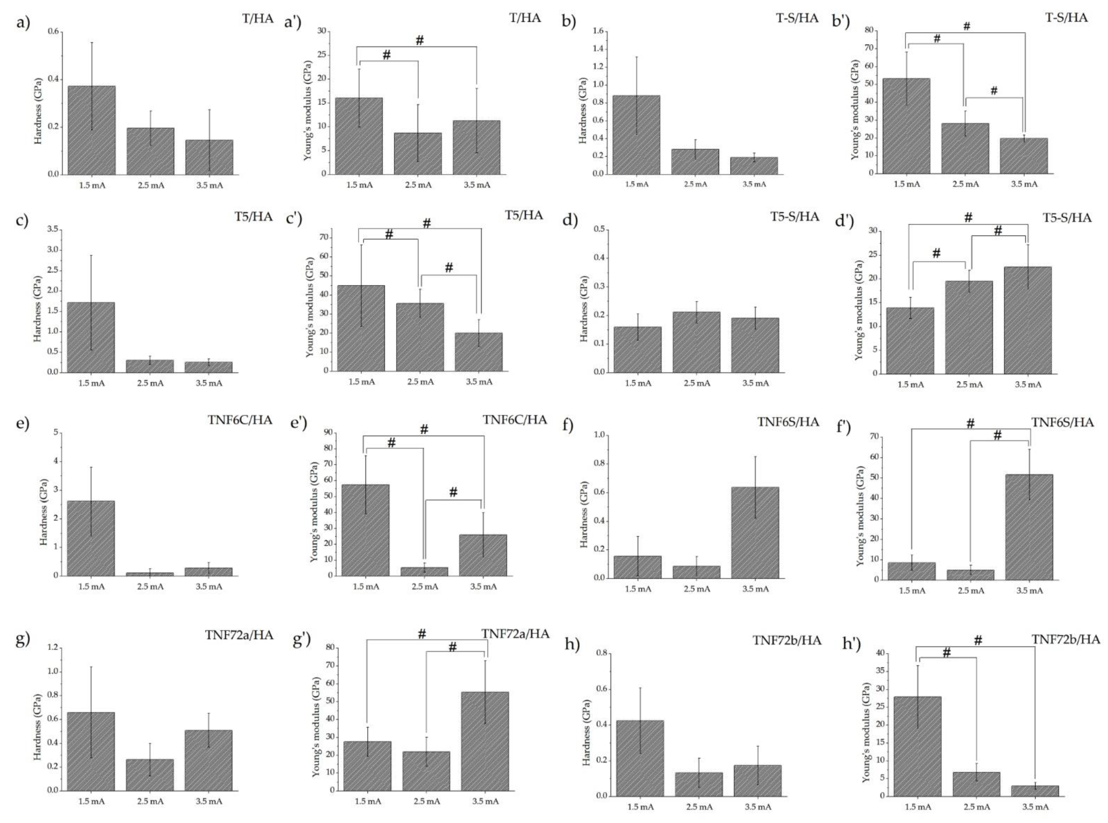
Figure 5 shows the results of the measurements of nanomechanical properties. The main mechanical properties are hardness and Young’s modulus. Although the instrumental values of these parameters are obtained in the nanoindentation test, they provide an overview and the opportunity to compare these properties. The occurrence of high standard deviations in nanoindentation studies of porous ceramic materials, such as hydroxyapatite coatings, are normal occurrences. In addition, when correlating the mechanical test results with SEM images of the tested specimens, it should be noted that in the case of hydroxyapatite coatings obtained at the lowest current value (1.5 mA), the coatings are characterized by unevenness. The test results presented probably concern either the coating or the substrate material. Figure S5a,b shows the nanohardness and Young’s modulus T-S and T5-S specimens. In the case of T-S and T5-S samples, no effect of modification on the hardness value was observed, only in T5-S did the value of Young’s modulus increased almost twice. For the rest of the tested materials, the results obtained indicate that there is no significant effect of the modification manufacturing parameters on hardness. In the case of Young’s modulus, the obtained results of nanomechanical properties indicate that the influence is significant for most samples. Increasing the deposition current from 1.5 mA to 3.5 mA for all tested specimens had a significant effect on the value of reduced Young’s modulus. An increase in Young’s modulus with increasing deposition current was observed for the T5-S/HA samples, while a decrease in Young’s modulus with increasing current was observed for T-S/HA, T5/HA, and TNF72b/HA. The optimal mechanical properties of the implants for biomechanical compatibility should be as close as possible to human cortical bone (hardness 0.3–0.7 GPa and Young’s modulus ~20 GPa), but it is Young’s modulus that is crucial. In the case of the tested materials, a Young’s modulus close to that of bone, with appropriate hardness, was obtained for TS-HA (2.5 mA), T5/HA (3.5 mA), TNF6C/HA (3.5 mA), and TNF72a/HA (1.5 mA) samples. However, due to the previous description of the HA coating inhomogeneity for a low value of deposition current (1.5mA), TNF72a/HA samples should not be considered. Comparing the results of the nanomechanical tests with previous studies for all the samples tested, the hardness and Young’s modulus results obtained are lower on specimens with the hydroxyapatite coating than without it [10,39]. A significant decrease in these properties was observed in all tested specimens. The decrease in mechanical values obtained for the samples with hydroxyapatite (for deposition current values of 2.5 and 3.5 mA) confirms that the nanoindentation tests were for the coatings and not for the substrate.
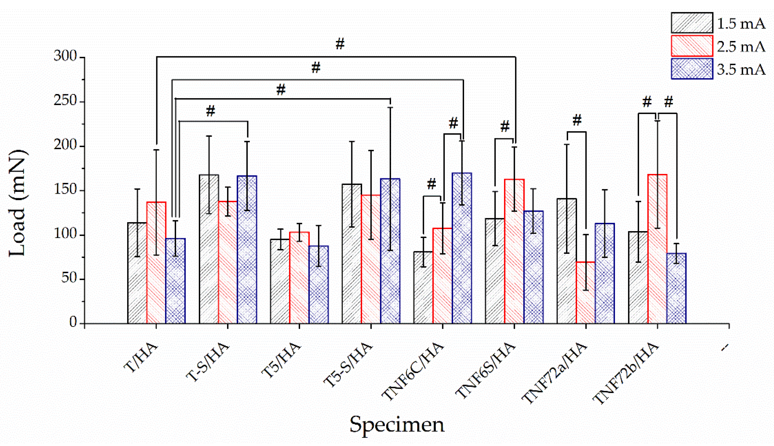
The results of the nanoscratch-test measurements for TS and T5-S samples (Figure S5c) indicate that there is no effect of the modification parameters on its adhesion. Figure 6 shows the results of the nanoscratch-test measurements. The effect of deposition current on adhesion was observed for samples from the TNF6C/HA, TNF6S/HA, TNF72a/HA, and TNF72b/HA groups. However, strict correlations were not observed for these groups: for TNF6C/HA samples, an increase in adhesion was observed with increasing intensity: for TNF6S/HA and TNF72b/HA samples, an initial increase, then a decrease; for TNF72a/HA, an initial decrease, then an increase. Significant differences between HA coatings deposited at the same current value relative to HA coatings deposited on unmodified titanium (specimens T/HA) were obtained for TNF6S/HA (2.5 mA), T-S/HA (3.5 mA), T5-S/HA (3.5 mA), and TNF6C/HA (3.5 mA) specimens. Improved adhesion was observed in all the above. For all tested materials, the best mechanical properties (relative to human cortical bone), while maintaining the highest adhesion value, were characterized by samples from the TNF6C/HA group (3.5 mA).

4. Discussion

The search for optimal conditions of the cathodic electrodeposition of HA on the surface of titanium implants/titanium alloys is one of the crucial issues that research on the design and manufacture of modern implants is focused on [16,30,51,60,61,62]. Electrodeposition is used in surface engineering electrochemical techniques, in which two electrodes (connected to an electrical generator) are immersed in an aqueous solution containing calcium and phosphate ions [16,17,26,63]. It should be noted that besides the deposition process conditions, the substrate’s type and properties directly impact the morphology, structure, and mechanical and biological properties of the produced HA layers. Therefore, our research aimed to select the suitable, universal, and reproducible conditions for the cathodic deposition of HA on the surfaces of Ti6Al4V alloy biomaterials with different surface morphologies and appropriate mechanical properties.
The electrolyte used during the HA electrodeposition consisted of calcium nitrate tetrahydrate ((CaNO3)2·4H2O) and ammonium dihydrogen phosphate (NH4(H2PO4) [17,51,52,64,65,66,67]. However, in all our experiments, the electrolyte mentioned above was enriched by adding ethylenediaminetetraacetic acid disodium salt (EDTA-2Na). The analysis of the literature data showed that the use of the chelating agent, which is ethylenediaminetetraacetic acid (EDTA), on the properties, morphology, and crystallinity of HA layers deposited on titanium implants has not been fully uncovered so far [47,64,65,68]. According to Zhao et al. [69], the addition of the EDTA-2Na (c = 3.5 · 10−2 M) to the electrolyte improved the corrosion resistance and the crystallinity of formed HA layers. It was noted that the increase in the biodegradability of these layers affects the formation of calcium phosphate particles. Morphologically, the resulting HA layers on the magnesium alloy resembled flowers [69]. He et al. [45], studying the effect of EDTA on the deposition of HA coating on Ti6Al4V alloy surface. According to this report, in the absence of a chelating agent, the HA crystals formed were not very dense and had a needle- or rod-like shape, which was consistent with our results. Moreover, no effect of EDTA on changes in the phase composition of the HA layer was found. He et al. proved that increasing EDTA concentration decreases the thickness of the hydroxyapatite layer, which is associated with a decreasing concentration of available calcium ions in the solution. The bonding force between the substrate and the HA layer achieved a maximum value of 16.8 MPa when the EDTA-2Na concentration was 7.5 · 10−4 M (the bonding force in this experiments was assessed on the basis of the HA layer breaking strength) [45]. The EDTA-2Na concentration used in our investigations amounted 1.5 · 10−3 M. Adhesion force between the substrate and the HA layer (measures using nanoindentation method) varied from 69 mN (TNF72a, I = 2.5 mA) up to 170 mN (TNF6C/HA, I = 3.5mA), depending on the type of surface modification. This issue will be discussed in a later part of this paper. Court et al. [58] pointed out that the electrodeposition temperature also affects the morphology and structure of hydroxyapatite layers on titanium substrates. The HA layers revealed homogenous plate-like structures. However, deposition at 348 K led to denser coatings, covering the whole surface with a more compact layer than in deposition at 323 K. At lower temperatures, the deposition rate of the HA layer was lower, and the resulting layers were thinner. HA layers deposited at 348 K were more hydrophilic (contact angle 27.4°) than those deposited at 323 K (contact angle 76.1°) [58]. In our experiments, hydroxyapatite was deposited on modified titanium alloy surfaces of different morphology at 338 K as an optimal temperature. The analysis of the XRD patterns of studied samples revealed that the intensity of peaks assigned to HA layers was the greatest. Moreover, all produced hydroxyapatite layers showed superhydrophilic properties, which is highly desirable for biomedical applications [23,58,59,70].
It is assumed that the formation of hydrophilic coatings promotes apatite growth due to the increased ion exchange capacity from the SBF solution [42,44]. This effect is consistent with our earlier investigations on apatite growth on intermediate TiO2 and titanate coatings. The apatite growth from SBF solution was noticed on amphiphilic titanate substrates, but it was not observed for the hydrophobic TiO2 nanoporous surfaces [38]. Superhydrophilic surfaces exhibit increased surface tension and a high potential to form hydrated layers with surrounding water molecules through the hydrogen bonds [23,60,61,62,71,72]. He et al. [45], studying the issue of the substrate influence on the formation of the HA layer, used the electrodeposition method on a pre-treated alkali-sodium Ti6Al4V substrate. They showed that by varying the current density values between 1.25 and 3.61 mA/cm2, no differences in the composition and grain size of the hydroxyapatite layer are observed. However, as the current density increases, the thickness of the HA layers increases and the crystal structure changes from porous to dense (1.25–2.5 mA/cm2) and back to porous (2.5–3.61 mA/cm2) [45]. Meanwhile Gu et al. [63] obtained the most homogeneous HA layers using lower current densities, i.e., 5 mA/cm2. They observed that the higher the current density, the more heterogeneous the layer. At a current density of 10 mA/cm2, they obtained a non-uniform coating of seaweed-like crystals with different grain sizes [63]. In contrast, Chakraborty et al. [64] exhibited that the 10 mA/cm2 as the most optimal current density. The hydroxyapatite layers on SS316 substrate obtained at this value are porous, crystallite sizes in the nano range [64]. There are also reports that an increase in current density from 10 to 20 mA/cm2 leads to an increased volume fraction of microcracks, changing surface cracks to cracks formed along the deposited layer’s cross-sections [41,65,66,67,68].
Searching for the optimal conditions of the cathodic electrodeposition of HA layers on Ti6Al4V substrates, we decided to study the influence of current densities (input: J = 7.5 mA/cm2 (I = 1.5 mA), J = 12.5 mA/cm2 (I = 2.5 mA), and J = 17.5 mA/cm2 (I= 3.5 mA)) on the physicochemical and mechanical properties of the produced coatings. Our results were compatible with most earlier reports concerning the HA layer deposition on the pure titanium alloy. A current density of 17.5 mA/cm2 lead to numerous micro-cracks, delaminating the HA layer from the substrate. It can be attributed to the increased cathodic hydrogen evolution reaction (released with increasing current density), leading to the cracking and the porous structure formation of the HA layer [21,45,73,74]. However, we observe that the influence of the type of surface modification used on the Ti6Al4V alloy substrate has a significant effect on the hydroxyapatite layers formed. The applied current I = 1.5 mA (J = 7.5 mA/cm2) is too low for the formation of hydroxyapatite crystals in the case of hydroxyapatite deposition on T5 porous or TNF6 nanofibrous coating. On the surfaces of pre-treated sodium-alkali samples, i.e., T-S and T5-S HA, hydroxyapatite forms nanoplates dispersed over the coating surface. Whereas on the surface of nanofibrous TNF72 we observe the formation of HA in the form of flower-like (TNF72a) or nanoplatelets (TNF72b). We observed no visible changes in the morphology of hydroxyapatite crystals between the applied current density value of 12.5 mA/cm2 (I = 2.5 mA) and 17.5 mA/cm2 (I = 3.5 mA). For all tested substrates, the hydroxyapatite layers show a floral morphology composed of numerous nanoplatelets. When current density increases, the change of HA crystalline structure from dispersed to densely packed is visible, and the thickness of HA layers grows. The modification of the titanium substrate had no significant effect on the thickness of the HA layers obtained when the current density was 12.5 mA/cm2. The obtained layer thicknesses were between 11.61 µm (TNF6C) and 12.90 µm (TNF72a). The exception at 2.5 and 3.5 mA was the TNF72b sample, for which the layer obtained was the thickest at 14.51 and 20.8 µm, respectively. This layer also exhibited the weakest mechanical properties. At a current intensity of 3.5 mA, we noted wider differences in layer thicknesses depending on the coating on which the hydroxyapatite was deposited. The obtained layer thicknesses ranged from 13.60 µm (TNF6C) to 17.60 µm (T-S).
In order to determine which of the Ti6Al4V surface modifications is most desirable for the deposition of hydroxyapatite layers, mechanical studies were crucial. Improving the mechanical strength of hydroxyapatite layers has been a challenge for many years. The interfacial adhesion of HA to the substrate is weak [21,30,43,75,76,77]. In our research, to increase the adhesion between the substrate and the hydroxyapatite layer, we used intermediate coatings in the form of nanotubes (T5), nanofibres (TNF), and titanates (T-S, T5-S). We had previously analyzed the chosen nanocoatings in depth for their physicochemical, mechanical, and biointegrative properties [10,11,38,39,40]. Integrating them into the HA layer brings many benefits related to increasing the implant’s bioactivity and improving the HA layers’ mechanical properties. The obtained HA layers were characterized in terms of adhesion, hardness, and Young’s modulus. In order to avoid the shielding effect, which is associated with a significant loss of bone mass, it is aimed that Young’s modulus of the implants is close to the elastic modulus of cortical bone (about 20 GPa) [78,79].
The previous reports suggest that the increased interfacial adhesion strength between the titanium implant and the apatite layer is due to the roughness of the biomaterial surface [80,81,82,83]. It is thought that a larger surface area and physical blockage are generated between the nanotube coating and the apatite layer [80,81,82,83]. Our research confirmed that the substrate’s surface roughness affects the hydroxyapatite layer’s obtained mechanical properties. Our produced intermediate oxide coatings show high surface roughness parameters (Sa) compared to the unmodified titanium alloy [10,39]. We observed the highest value of the Sa parameter for the TNF6S intermediate nanofibrous coating (0.30 µm) and the lowest value for the TNF72a nanofibrous coating (0.06 µm) [39]. Using the cathodic HA deposition technique on intermediate coatings, we did not observe the delamination of the layer. In contrast, delamination was evident when depositing the HA layer directly onto a Ti6Al4V substrate (low value Sa = 0.02 µm) [10]. With the use of nanoporous (T5) titanate (T5-S and T5) coatings as interlayer systems, the dense HA layers with optimal mechanical properties were produced using a current of 2.5 mA. Young’s modulus for the samples mentioned above was close to that of cortical bone and was 35.58 GPa for T5/HA, 28.05 GPa for T-S/HA, and 19.50 GPa for T5-S/HA, respectively. Among the materials as mentioned earlier, the adhesion of HA layers was higher for the T-S (137.62 mN) and T5-S (145.22 mN) titanate coatings in comparison to T5/HA (103.11 mN) nanoporous coatings. This may be related to the formation of a bonding layer, i.e., CaTiO3 (chemical bonding) [43,84,85]. According to our previous studies, the Na2Ti3O7 layer supports spontaneous apatite deposition, as it is capable of actively exchanging calcium cations in a simulated SBF body fluid solution, thus converting to calcium titanate. The T5-S layer formed by the alkali-sodium treatment of the T5 nanoporous coating shows faster apatite growth in SBF solution than the T-S layer formed by the alkali-sodium treatment of pure titanium alloy [38]. In addition, the rough surface resulting from the alkaline pretreatment increases the bonding strength [84,85,86,87]. Blackwood et al. [88] showed that the crystallinity and adhesion of HA could be improved by the sodium-alkali pretreatment of titanium. However, they suggested it is also crucial to additionally apply a heat treatment at 873 K or add H2O2 to the electrolyte [88]. Ahmadi et al. [25] reported that the production of a nanotube coating in the anodization process can significantly increase the adhesion strength of hydroxyapatite to the substrate. The bond strength for the HA/Ti6Al4V system was 12.8 ± 2 MPa, while for the HA/TiO2 nanotube nanocomposite it was 23.1 ± 4 MPa. The formation of a rough surface at the HA/TiO2 nanotube interface strengthens the cohesion forces. As a result of filling the voids, a compact HA/TiO2 layer is formed. It can also be seen that titanium dioxide nanoparticles in the HA layer are able to relax residual stresses, which are usually responsible for microcracks in the hydroxyapatite deposition process [25,89,90]. Besides the anodization process, the sodium-alkali treatment, a variety of etchants, such as HNO3, H2SO4, HCl, and HF, are commonly used to pretreat the substrate. Using the compounds mentioned above in concentrations between 50 and 75% improved the adhesion strength at the coating/implant interface [21,91,92,93,94,95]. As an intermediate coating between the titanium alloy substrate and the HA coating, we also used TiO2 nanofibres (TNF). These studies revealed that some samples were chemically etched in a mixture of concentrated HCl and H2O and then heated in a 30% H2O2 solution at 358 K for 6 h. Depending on the heating procedure, the samples were designated as TNF6S (heating in an incubator) and TNF6C (heating under a reflux condenser). Another sample was etched, respectively, in (a) 2 M HF solution for 10 s (TNF72a), (b) in a 1:4:5 mixture of HF:HNO3:H2O for 30 s (TNF72b), and then heated in 30 wt.% H2O2 solution at 358 K for 72h. The obtained TNF samples are amorphous and contain rutile (TNF72) or anatase (TNF6) phase domains [39,40]. In contrast to nanoporous and titanate samples, we noticed that the optimum mechanical properties of electrodeposition of HA layers on nanofibrous coatings are obtained at 3.5 mA (except TNF72b). Generally, the TNF72b/HA sample at both 2.5 mA and 3.5 mA exhibits the weakest hardness (0.13 and 0.17 GPa, respectively) and a very low Young’s modulus (6.81 GPa and 2.98 GPa, respectively) compared to other biomaterials. Surprisingly, the adhesion strength of the HA layers to the TNF72b coating is high at 2.5 mA and is 168.25 mN. As the current increases to 3.5 mA, it rapidly decreases to 79.25 mN. It possibly can be related to a too-thick deposited HA layer on the TNF72b coating. In this case, the deposition of the thickest HA layer (20.8 um) was noticed. The TNF6C/HA sample exhibits the best mechanical properties of all analyzed samples, where the current intensity was 3.5 mA. The thickness of the resulting HA layer is 13.60 um. The Young’s modulus is close to that of cortical bone and was 25.96 GPa, while the adhesion force is 169.93 mN. So far, there are no reports on the electrodeposition of the hydroxyapatite on nanofibrous Ti6Al4V substrates.
Robertson et al. [96] presented a different approach to this issue and used a sol-gel method to deposit hydroxyapatite on a Ti6Al4V–ELI substrate, obtaining the layer with a thickness of 73.3 um. They also tested anodized Ti6Al4V with an HA layer, for which the thickness increased to 84.97 um. However, it should be noted that the main function of the oxide intermediate coatings is to improve the adhesion of the ceramic hydroxyapatite layer to the titanium substrate, so the smaller the thickness of the HA layer, the more chance of avoiding its delamination and introducing additional stresses. In the method we used, the thickness of the HA layers obtained varied between 9.67 µm (T/HA I = 2.5mA) and 20.80 µm (TNF72b I = 3.5 mA), depending on the intermediate coating used and the applied current. An additional advantage of using the cathodic deposition method is that the deposition and sintering time of the hydroxyapatite layer is significantly shorter, and the ageing step (necessary in the case of the sol-gel method) is omitted, which increases the chances of using this method in industry [97,98]. Commercially, the most commonly used method for the deposition of hydroxyapatite coatings is plasma spraying. The resulting layers typically achieve thicknesses in the range of 20–50 µm [99]. However, the limitations of this method are mainly the high energy and temperature of the plasma, which can cause rapid thermal decomposition of HA and numerous residual stresses [100]. Singh et al. showed that in plasma-sprayed coatings, the hydroxyapatite particles on the Ti6Al4V alloy melt completely or partially due to the high plasma temperature. The researchers obtained a very high surface roughness value (Ra = 5.43 µm) for the Ti6Al4V/HA systems [37]. The Ra value obtained is nearly ten times higher than that achieved in our study (0.57 µm for T/HA). Plasma-sprayed HA coatings have a much rougher surface compared to HA coatings produced by cathodic deposition or sol-gel [37,96]. By applying plasma spraying with induction preheating (400–600 °C), Fomin et al. [101] revealed that the resulting HA layers on Ti implants exhibited a stoichiometric-like chemical composition, a homogeneous nanostructure, and morphologically resembled micro-sized splats with numerous nanograins. Moreover, the HA layers on Ti substrates showed high hardness in the range of 0.9–12 GPa and elastic modulus in the range of 7–16 GPa. Unfortunately, during this work, the adhesion strength between the coating and the substrate was not determined. The results of our research revealed that the morphology of the produced HA coatings was more floral, with numerous nanoplatelets. Moreover, the produced HA layers exhibited close mechanical parameters to cortical bone (H = 0.29 GPa, Young’s modulus = 25.96 GPa) and high adhesion force = 169.93 mN for the TNF6C/HA sample. Ritwik et al. [102] produced a thin layer (30 µm) of hydroxyapatite on a Ti6Al4V substrate using a dip-coating process. They used shellac (a natural resin) as an intermediate coating. The researchers showed that the deposition of a shellac layer between the HA and the Ti6Al4V substrate increases the adhesion force from 1.08 MPa (Ti6Al4V/HA) to 7.14 MPa (Ti6Al4V/Shellac/HA). The average surface roughness (Ra) values measured were 0.93 µm [102]. The cathodic deposition of hydroxyapatite, which we optimized, allowed us to obtain thinner hydroxyapatite layers (from 10 µm to 20 µm, depending on the type of intermediate coating used) and two to three times lower roughness.

5. Conclusions

In order to increase the adhesion strength of hydroxyapatite layers (HA) to Ti6Al4V alloy substrates, we researched the morphology, structure, and mechanical properties of HA layers deposited by the cathodic electrodeposition method. The results proved that the above coatings’ parameters depend not only on temperature, time, current density, and the addition of EDTA-2Na to the electrolyte solution but also on the method of the pre-modification of the alloy surface. The fabrication of an intermediate layer between Ti6Al4V substrates surface and hydroxyapatite coating, which could be the TiO2 nanoporous layer (T5), TiO2 nanofiber (TNF6, TNF72), and titanate (T5-S, T-S), significantly improve the mechanical properties of the HA layers. Our investigations revealed that Ti6Al4V/TNF6C system (i.e., TiO2 nanofibrous coatings formed by chemical oxidation in a 30% H2O2 solution at 358 K under a reflux condenser) is the most appropriate for the fabrication of implants covered with a mechanical permanent hydroxyapatite layer. However, the obtained physicochemical and mechanical parameters are also satisfactory for the other intermediate layers, i.e., T5, T5-S, T-S, and TNF6S with a hydroxyapatite layer. Double-layer coatings (TNF6C/HA, T5/HA, T-S/HA, T5-S/HA, and TNF6S/HA) offer very promising results (the mechanical properties like human cortical bone), which can be used in the construction of modern orthopedic or dental implants.
In the next step of our research, in vitro investigations of the biomaterials mentioned above will be conducted to confirm their potential medical applications. We will focus on Ti6Al4V/intermediate layer/HA systems, investigating their effects on the survival and proliferation of human MG-63 osteoblasts-like, mouse L929 fibroblast, and adipose-derived human mesenchymal stem cell (ADSC) cultures seeded on their surface in vitro. We will also determine the antimicrobial activity of the produced systems. Results on the apatite-forming ability of coatings immersed in simulated body fluid (SBF) will be presented.

Supplementary Materials

The following supporting information can be downloaded at: https://www.mdpi.com/article/10.3390/ma15196925/s1; Figure S1: SEM cross-section images of the T/HA (a), T-S/HA (b), T5/HA (c), T5-S/HA (d), TNF6C/HA (e), TNF6S/HA (f), TNF72a/HA (g), and TNF72b/HA (h) samples at 2.5 mA current.; Figure S2: SEM cross-section images of the T/HA (a), T-S/HA (b), T5/HA (c), T5-S/HA (d), TNF6C/HA (e), TNF6S/HA (f), TNF72a/HA (g), and TNF72b/HA (h) samples at 3.5 mA current; Figure S3: Energy-dispersive spectroscopy (EDS) spectra and quantitative data of the T5-S samples with hydroxyapatite layers at various currents: 1.5 mA (a), 2.5 mA (b), and 3.5 mA (c); Figure S4: DRIFT spectra of studied T/HA (a), T-S/HA (b), T5/HA (c), T5-S/HA (d), TNF6C/HA (e), TNF6S/HA (f), TNF72a/HA (g), and TNF72b/HA (h) samples at various currents (1.5, 2.5, 3.5 mA); Figure S5: Nanomechanical properties (hardness—left and Young’s modulus—right) of T-S and T5-S specimens.

Author Contributions

Conceptualization, M.E., P.P. and A.R.; methodology, M.E., P.P. and A.R.; validation, M.E. and M.B.; formal analysis, M.E., P.P. and A.R.; investigation, M.E. and M.B.; resources, M.E.; data curation, M.E.; writing—original draft preparation, M.E. and M.B.; writing—review and editing, M.E., P.P. and A.R.; supervision, P.P.; project administration, M.E.; funding acquisition, M.E. All authors have read and agreed to the published version of the manuscript.

Funding

This research was funded by Research Nicolaus Copernicus University in Toruń—Excellence Initiative, Grants4NCUStudents number 2403. The Ministry of Science and Higher Education and Nano-implant Ltd. also funded this research through the PhD studies of Michalina Ehlert. The APC was waived by MDPI.

Institutional Review Board Statement

Not applicable.

Informed Consent Statement

Not applicable.

Data Availability Statement

Data sharing is not applicable in this article.

Conflicts of Interest

The authors declare no conflict of interest. The funders had no role in the design of the study; in the collection, analyses, or interpretation of data; in the writing of the manuscript; or in the decision to publish the results.

References

  1. Geetha, M.; Singh, A.K.; Asokamani, R.; Gogia, A.K. Ti Based Biomaterials, the Ultimate Choice for Orthopaedic Implants—A Review. Prog. Mater. Sci. 2009, 54, 397–425. [Google Scholar] [CrossRef]
  2. Attar, H.; Löber, L.; Funk, A.; Calin, M.; Zhang, L.C.; Prashanth, K.G.; Scudino, S.; Zhang, Y.S.; Eckert, J. Mechanical Behavior of Porous Commercially Pure Ti and Ti–TiB Composite Materials Manufactured by Selective Laser Melting. Mater. Sci. Eng. A 2015, 625, 350–356. [Google Scholar] [CrossRef]
  3. Gain, A.K.; Zhang, L.; Quadir, M.Z. Composites Matching the Properties of Human Cortical Bones: The Design of Porous Titanium-Zirconia (Ti-ZrO2) Nanocomposites Using Polymethyl Methacrylate Powders. Mater. Sci. Eng. A 2016, 662, 258–267. [Google Scholar] [CrossRef]
  4. Liu, S.; Shin, Y. Additive Manufacturing of Ti6Al4V Alloy: A Review. Mater. Des. 2018, 164, 107552. [Google Scholar] [CrossRef]
  5. Gain, A.K.; Zhang, L.; Lim, S. Tribological Behavior of Ti–6Al–4V Alloy: Subsurface Structure, Damage Mechanism and Mechanical Properties. Wear 2021, 464–465, 203551. [Google Scholar] [CrossRef]
  6. Sadeghi, M.; Kharaziha, M.; Salimijazi, H.R.; Tabesh, E. Role of Micro-Dimple Array Geometry on the Biological and Tribological Performance of Ti6Al4V for Biomedical Applications. Surf. Coat. Technol. 2019, 362, 282–292. [Google Scholar] [CrossRef]
  7. Sarker, A.; Tran, N.; Rifai, A.; Brandt, M.; Tran, P.A.; Leary, M.; Fox, K.; Williams, R. Rational Design of Additively Manufactured Ti6Al4V Implants to Control Staphylococcus Aureus Biofilm Formation. Materialia 2019, 5, 100250. [Google Scholar] [CrossRef]
  8. Chatzopoulos, G.S.; Wolff, L.F. Implant Failure and History of Failed Endodontic Treatment: A Retrospective Case-Control Study. J. Clin. Exp. Dent. 2017, 9, e1322–e1328. [Google Scholar] [CrossRef]
  9. Liu, J.; Liu, J.; Attarilar, S.; Wang, C.; Tamaddon, M.; Yang, C.; Xie, K.; Yao, J.; Wang, L.; Liu, C.; et al. Nano-Modified Titanium Implant Materials: A Way Toward Improved Antibacterial Properties. Front. Bioeng. Biotechnol. 2020, 8, 576969. [Google Scholar] [CrossRef]
  10. Ehlert, M.; Radtke, A.; Jędrzejewski, T.; Roszek, K.; Bartmański, M.; Piszczek, P. In Vitro Studies on Nanoporous, Nanotubular and Nanosponge-Like Titania Coatings, with the Use of Adipose-Derived Stem Cells. Materials 2020, 13, 1574. [Google Scholar] [CrossRef]
  11. Radtke, A.; Ehlert, M.; Jędrzejewski, T.; Bartmański, M. The Morphology, Structure, Mechanical Properties and Biocompatibility of Nanotubular Titania Coatings before and after Autoclaving Process. J. Clin. Med. 2019, 8, 272. [Google Scholar] [CrossRef] [PubMed] [Green Version]
  12. Ribeiro, M.; Monteiro, F.; Ferraz, M. Infection of Orthopedic Implants with Emphasis on Bacterial Adhesion Process and Techniques Used in Studying Bacterial-Material Interactions. Biomatter 2012, 2, 176–194. [Google Scholar] [CrossRef] [PubMed] [Green Version]
  13. Piszczek, P.; Radtke, A.; Ehlert, M.; Jędrzejewski, T.; Sznarkowska, A.; Sadowska, B.; Bartmański, M.; Erdoğan, Y.K.; Ercan, B.; Jędrzejczyk, W. Comprehensive Evaluation of the Biological Properties of Surface-Modified Titanium Alloy Implants. J. Clin. Med. 2020, 9, 342. [Google Scholar] [CrossRef] [PubMed] [Green Version]
  14. Radtke, A.; Grodzicka, M.; Ehlert, M.; Muzioł, T.M.; Szkodo, M.; Bartmański, M.; Piszczek, P. Studies on Silver Ions Releasing Processes and Mechanical Properties of Surface-Modified Titanium Alloy Implants. Int. J. Mol. Sci. 2018, 19, 3962. [Google Scholar] [CrossRef] [Green Version]
  15. Radtke, A.; Grodzicka, M.; Ehlert, M.; Jędrzejewski, T.; Wypij, M.; Golińska, P. “To Be Microbiocidal and Not to Be Cytotoxic at the Same Time…”-Silver Nanoparticles and Their Main Role on the Surface of Titanium Alloy Implants. J. Clin. Med. 2019, 8, 334. [Google Scholar] [CrossRef] [PubMed] [Green Version]
  16. Vranceanu, D.M.; Ungureanu, E.; Ionescu, I.C.; Parau, A.C.; Kiss, A.E.; Vladescu, A.; Cotrut, C.M. Electrochemical Surface Biofunctionalization of Titanium through Growth of TiO2 Nanotubes and Deposition of Zn Doped Hydroxyapatite. Coatings 2022, 12, 69. [Google Scholar] [CrossRef]
  17. Stocco, T.D.; Rodrigues, P.J.G.; Filho, M.A.d.A.; Lobo, A.O. Nanohydroxyapatite Electrodeposition onto Electrospun Nanofibers: Technique Overview and Tissue Engineering Applications. Bioengineering 2021, 8, 151. [Google Scholar] [CrossRef] [PubMed]
  18. Surmenev, R.A.; Surmeneva, M.A.; Ivanova, A.A. Significance of Calcium Phosphate Coatings for the Enhancement of New Bone Osteogenesis—A Review. Acta Biomater. 2014, 10, 557–579. [Google Scholar] [CrossRef]
  19. Brangule, A.; Gross, K.A. Importance of FTIR Spectra Deconvolution for the Analysis of Amorphous Calcium Phosphates. IOP Conf. Ser. Mater. Sci. Eng. 2015, 77, 012027. [Google Scholar] [CrossRef] [Green Version]
  20. Vecstaudza, J.; Gasik, M.; Locs, J. Amorphous Calcium Phosphate Materials: Formation, Structure and Thermal Behaviour. J. Eur. Ceram. Soc. 2019, 39, 1642–1649. [Google Scholar] [CrossRef]
  21. Safavi, M.S.; Walsh, F.C.; Surmeneva, M.A.; Surmenev, R.A.; Khalil-Allafi, J. Electrodeposited Hydroxyapatite-Based Biocoatings: Recent Progress and Future Challenges. Coatings 2021, 11, 110. [Google Scholar] [CrossRef]
  22. Radtke, A.; Ehlert, M.; Jędrzejewski, T.; Sadowska, B.; Więckowska-Szakiel, M.; Holopainen, J.; Ritala, M.; Leskelä, M.; Bartmański, M.; Szkodo, M.; et al. Titania Nanotubes/Hydroxyapatite Nanocomposites Produced with the Use of the Atomic Layer Deposition Technique: Estimation of Bioactivity and Nanomechanical Properties. Nanomaterials 2019, 9, 123. [Google Scholar] [CrossRef] [PubMed] [Green Version]
  23. Tian, M.; Cai, S.; Ling, L.; Zuo, Y.; Wang, Z.; Liu, P.; Bao, X.; Xu, G. Superhydrophilic Hydroxyapatite/Hydroxypropyltrimethyl Ammonium Chloride Chitosan Composite Coating for Enhancing the Antibacterial and Corrosion Resistance of Magnesium Alloy. Prog. Org. Coat. 2022, 165, 106745. [Google Scholar] [CrossRef]
  24. Panda, S.; Biswas, C.K.; Paul, S. A Comprehensive Review on the Preparation and Application of Calcium Hydroxyapatite: A Special Focus on Atomic Doping Methods for Bone Tissue Engineering. Ceram. Int. 2021, 47, 28122–28144. [Google Scholar] [CrossRef]
  25. Ahmadi, S.; Mohammadi, I.; Sadrnezhaad, S.K. Hydroxyapatite Based and Anodic Titania Nanotube Biocomposite Coatings: Fabrication, Characterization and Electrochemical Behavior. Surf. Coat. Technol. 2016, 287, 67–75. [Google Scholar] [CrossRef]
  26. Drevet, R.; Benhayoune, H. Electrodeposition of Calcium Phosphate Coatings on Metallic Substrates for Bone Implant Applications: A Review. Coatings 2022, 12, 539. [Google Scholar] [CrossRef]
  27. Taranu, B.-O.; Ianasi, P.; Rus, S.F.; Bucur, A.I. Simultaneous Precipitation and Electrodeposition of Hydroxyapatite Coatings at Different Temperatures on Various Metal Substrates. Coatings 2022, 12, 288. [Google Scholar] [CrossRef]
  28. Catauro, M.; Barrino, F.; Blanco, I.; Piccolella, S.; Pacifico, S. Use of the Sol–Gel Method for the Preparation of Coatings of Titanium Substrates with Hydroxyapatite for Biomedical Application. Coatings 2020, 10, 203. [Google Scholar] [CrossRef] [Green Version]
  29. Heimann, R.B. Structural Changes of Hydroxylapatite during Plasma Spraying: Raman and NMR Spectroscopy Results. Coatings 2021, 11, 987. [Google Scholar] [CrossRef]
  30. Mohseni, E.; Zalnezhad, E.; Bushroa, A.R. Comparative Investigation on the Adhesion of Hydroxyapatite Coating on Ti–6Al–4V Implant: A Review Paper. Int. J. Adhes. Adhes. 2014, 48, 238–257. [Google Scholar] [CrossRef]
  31. Vladescu, A.; Vranceanu, D.M.; Kulesza, S.; Ivanov, A.N.; Bramowicz, M.; Fedonnikov, A.S.; Braic, M.; Norkin, I.A.; Koptyug, A.; Kurtukova, M.O.; et al. Influence of the Electrolyte’s PH on the Properties of Electrochemically Deposited Hydroxyapatite Coating on Additively Manufactured Ti64 Alloy. Sci. Rep. 2017, 7, 16819. [Google Scholar] [CrossRef] [PubMed] [Green Version]
  32. Khlifi, K.; Dhiflaoui, H.; Ben Rhouma, A.; Faure, J.; Benhayoune, H.; Laarbi, A.B.C. Nanomechanical Behavior, Adhesion and Corrosion Resistance of Hydroxyapatite Coatings for Orthopedic Implant Applications. Coatings 2021, 11, 477. [Google Scholar] [CrossRef]
  33. Li, T.T.; Ling, L.; Lin, M.C.; Peng, H.K.; Ren, H.T.; Lou, C.W.; Lin, J.H. Recent Advances in Multifunctional Hydroxyapatite Coating by Electrochemical Deposition. J. Mater. Sci. 2020, 55, 6352–6374. [Google Scholar] [CrossRef]
  34. Nagentrau, M.; Tobi, A.L.M.; Jamian, S.; Otsuka, Y.; Hussin, R. Delamination-Fretting Wear Failure Evaluation at HAp-Ti-6Al–4V Interface of Uncemented Artificial Hip Implant. J. Mech. Behav. Biomed. Mater. 2021, 122, 104657. [Google Scholar] [CrossRef]
  35. Schönweger, F.; Sprecher, C.M.; Milz, S.; Dommann-Scherrer, C.; Meier, C.; Dommann, A.; Neels, A.; Wahl, P. New Insights into Osteointegration and Delamination from a Multidisciplinary Investigation of a Failed Hydroxyapatite-Coated Hip Joint Replacement. Materials 2020, 13, 4713. [Google Scholar] [CrossRef] [PubMed]
  36. Ammarullah, M.I.; Afif, I.Y.; Maula, M.I.; Winarni, T.I.; Tauviqirrahman, M.; Jamari, J. Tresca Stress Evaluation of Metal-on-UHMWPE Total Hip Arthroplasty during Peak Loading from Normal Walking Activity. Mater. Today Proc. 2022, 63, S143–S146. [Google Scholar] [CrossRef]
  37. Singh, G.; Singh, H.; Sidhu, B.S. Characterization and Corrosion Resistance of Plasma Sprayed HA and HA–SiO2 Coatings on Ti–6Al–4V. Surf. Coat. Technol. 2013, 228, 242–247. [Google Scholar] [CrossRef]
  38. Ehlert, M.; Radtke, A.; Roszek, K.; Jędrzejewski, T.; Piszczek, P. Assessment of Titanate Nanolayers in Terms of Their Physicochemical and Biological Properties. Materials 2021, 14, 806. [Google Scholar] [CrossRef]
  39. Ehlert, M.; Roszek, K.; Jędrzejewski, T.; Bartmański, M.; Radtke, A. Titania Nanofiber Scaffolds with Enhanced Biointegration Activity—Preliminary In Vitro Studies. Int. J. Mol. Sci. 2019, 20, 5642. [Google Scholar] [CrossRef] [Green Version]
  40. Ehlert, M.; Radtke, A.; Topolski, A.; Śmigiel, J.; Piszczek, P. The Photocatalytic Activity of Titania Coatings Produced by Electrochemical and Chemical Oxidation of Ti6Al4V Substrate, Estimated According to ISO 10678:2010. Materials 2020, 13, 2649. [Google Scholar] [CrossRef]
  41. Lin, D.-Y.; Wang, X.-X. Electrodeposition of Hydroxyapatite Coating on CoNiCrMo Substrate in Dilute Solution. Surf. Coat. Technol. 2010, 204, 3205–3213. [Google Scholar] [CrossRef]
  42. Huang, Y.; Hao, M.; Nian, X.; Qiao, H.; Zhang, X.; Zhang, X.; Song, G.; Guo, J.; Pang, X.; Zhang, H. Strontium and Copper Co-Substituted Hydroxyapatite-Based Coatings with Improved Antibacterial Activity and Cytocompatibility Fabricated by Electrodeposition. Ceram. Int. 2016, 42, 11876–11888. [Google Scholar] [CrossRef]
  43. Xiao, X.F.; Liu, R.F.; Zheng, Y.Z. Characterization of Hydroxyapatite/Titania Composite Coatings Codeposited by a Hydrothermal–Electrochemical Method on Titanium. Surf. Coat. Technol. 2006, 200, 4406–4413. [Google Scholar] [CrossRef]
  44. Huang, Y.; Zhang, X.; Zhang, H.; Qiao, H.; Zhang, X.; Jia, T.; Han, S.; Gao, Y.; Xiao, H.; Yang, H. Fabrication of Silver- and Strontium-Doped Hydroxyapatite/TiO2 Nanotube Bilayer Coatings for Enhancing Bactericidal Effect and Osteoinductivity. Ceram. Int. 2017, 43, 992–1007. [Google Scholar] [CrossRef]
  45. He, D.-H.; Wang, P.; Liu, P.; Liu, X.-K.; Ma, F.-C.; Zhao, J. HA Coating Fabricated by Electrochemical Deposition on Modified Ti6Al4V Alloy. Surf. Coat. Technol. 2016, 301, 6–12. [Google Scholar] [CrossRef]
  46. Zeng, H.; Lacefield, W.R. XPS, EDX and FTIR Analysis of Pulsed Laser Deposited Calcium Phosphate Bioceramic Coatings: The Effects of Various Process Parameters. Biomaterials 2000, 21, 23–30. [Google Scholar] [CrossRef]
  47. Rehman, I.; Bonfield, W. Characterization of Hydroxyapatite and Carbonated Apatite by Photo Acoustic FTIR Spectroscopy. J. Mater. Sci. Mater. Med. 1997, 8, 1–4. [Google Scholar] [CrossRef]
  48. Barinov, S.M.; Rau, J.V.; Cesaro, S.N.; Durisin, J.; Fadeeva, I.V.; Ferro, D.; Medvecky, L.; Trionfetti, G. Carbonate Release from Carbonated Hydroxyapatite in the Wide Temperature Rage. J. Mater. Sci. Mater. Med. 2006, 17, 597–604. [Google Scholar] [CrossRef]
  49. Berzina-Cimdina, L.; Borodajenko, N. Research of Calcium Phosphates Using Fourier Transform Infrared Spectroscopy. In Infrared Spectroscopy—Materials Science, Engineering and Technology; Theophanides, T., Ed.; InTech: London, UK, 2012; ISBN 978-953-51-0537-4. [Google Scholar]
  50. Wei, D.; Zhou, Y.; Jia, D.; Wang, Y. Biomimetic Apatite Deposited on Microarc Oxidized Anatase-Based Ceramic Coating. Ceram. Int. 2008, 34, 1139–1144. [Google Scholar] [CrossRef]
  51. Tsuchiya, H.; Macak, J.M.; Müller, L.; Kunze, J.; Müller, F.; Greil, P.; Virtanen, S.; Schmuki, P. Hydroxyapatite Growth on Anodic TiO2 Nanotubes. J. Biomed. Mater. Res. A 2006, 77, 534–541. [Google Scholar] [CrossRef]
  52. Ramesh, S.T.; Rameshbabu, N.; Gandhimathi, R.; Nidheesh, P.V.; Kumar, M.S. Kinetics and Equilibrium Studies for the Removal of Heavy Metals in Both Single and Binary Systems Using Hydroxyapatite. Appl. Water Sci. 2012, 2, 187–197. [Google Scholar] [CrossRef] [Green Version]
  53. Elliott, J.C. Structure and Chemistry of the Apatites and Other Calcium Orthophosphates, 1st ed.; Studies in Inorganic Chemistry; Elsevier: London, UK, 1994; Volume 18, ISBN 978-1-4832-9031-7. [Google Scholar]
  54. El Boujaady, H.; Mouraber, M.; El Rhilassi, A.; Bennani-Ziatni, M.; El Hamri, R.; Tajtai, A. Adsorption of a Textile Dye on Synthesized Calcium Deficient Hydroxyapatite (CDHAp): Kinetic and Thermodynamic Studies. J. Mater. Env. Sci. 2016, 7, 4049–4063. [Google Scholar]
  55. Ronan, K.; Kannan, M.B. Novel Sustainable Route for Synthesis of Hydroxyapatite Biomaterial from Biowastes. ACS Sustain. Chem. Eng. 2017, 5, 2237–2245. [Google Scholar] [CrossRef]
  56. Tripathy, A.; Sharma, P.; Sahoo, N.; Pramanik, S.; Abu Osman, N.A. Moisture Sensitive Inimitable Armalcolite/PDMS Flexible Sensor: A New Entry. Sens. Actuators B Chem. 2018, 262, 211–220. [Google Scholar] [CrossRef]
  57. Bohre, A.; Avasthi, K.; Singh, B.; Shrivastava, O.P. Crystallographic Evaluation of Titanate Ceramics as a Host Structure for Immobilization of Samarium. Radiochemistry 2014, 56, 92–97. [Google Scholar] [CrossRef]
  58. Cotrut, C.M.; Vladescu, A.; Dinu, M.; Vranceanu, D.M. Influence of Deposition Temperature on the Properties of Hydroxyapatite Obtained by Electrochemical Assisted Deposition. Ceram. Int. 2018, 44, 669–677. [Google Scholar] [CrossRef]
  59. Du, J.; Wang, G.; Song, D.; Jiang, J.; Jiang, H.; Gao, J. In-Vitro Degradation Behavior and Biocompatibility of Superhydrophilic Hydroxyapatite Coating on Mg–2Zn–Mn–Ca–Ce Alloy. J. Mater. Res. Technol. 2022, 17, 2742–2754. [Google Scholar] [CrossRef]
  60. Yang, Y.; Ao, H.; Wang, Y.; Lin, W.; Yang, S.; Zhang, S.; Yu, Z.; Tang, T. Cytocompatibility with Osteogenic Cells and Enhanced in Vivo Anti-Infection Potential of Quaternized Chitosan-Loaded Titania Nanotubes. Bone Res. 2016, 4, 16027. [Google Scholar] [CrossRef]
  61. Bai, Y.; Zhang, H.; Shao, Y.; Zhang, H.; Zhu, J. Recent Progresses of Superhydrophobic Coatings in Different Application Fields: An Overview. Coatings 2021, 11, 116. [Google Scholar] [CrossRef]
  62. Li, W.; Zhan, Y.; Yu, S. Applications of Superhydrophobic Coatings in Anti-Icing: Theory, Mechanisms, Impact Factors, Challenges and Perspectives. Prog. Org. Coat. 2021, 152, 106117. [Google Scholar] [CrossRef]
  63. Gu, C.G.; Fu, Q.-G.; Li, H.; Lu, J.H.; Zhang, L.L. Study on Special Morphology Hydroxyapatite Bioactive Coating by Electrochemical Deposition. Key Eng. Mater. 2013, 537, 256–260. [Google Scholar] [CrossRef]
  64. Chakraborty, R.; Sengupta, S.; Saha, P.; Das, S. Synthesis of Biocompatible Calcium Hydrogen Phosphate and Hydroxyapatite Coating on SS316 Substrate through Pulsed Electrodeposition. Mater. Sci. Eng. C 2016, 69, 875–883. [Google Scholar] [CrossRef] [PubMed]
  65. Han, Y.; Fu, T.; Lu, J.; Xu, K. Characterization and Stability of Hydroxyapatite Coatings Prepared by an Electrodeposition and Alkaline-Treatment Process. J. Biomed. Mater. Res. 2001, 54, 96–101. [Google Scholar] [CrossRef]
  66. Gopi, D.; Indira, J.; Kavitha, L. A Comparative Study on the Direct and Pulsed Current Electrodeposition of Hydroxyapatite Coatings on Surgical Grade Stainless Steel. Surf. Coat. Technol. 2012, 206, 2859–2869. [Google Scholar] [CrossRef]
  67. Marashi-Najafi, F.; Khalil-Allafi, J.; Etminanfar, M.R.; Faezi-Alivand, R. Corrosion Resistance and in Vitro Evaluation of the Pulsed Current Electrodeposited Hydroxyapatite Coatings on Nitinol Shape Memory Alloy. Mater. Corros. 2017, 68, 1237–1245. [Google Scholar] [CrossRef]
  68. Gopi, D.; Prakash, V.C.A.; Kavitha, L.; Kannan, S.; Bhalaji, P.R.; Shinyjoy, E.; Ferreira, J.M.F. A Facile Electrodeposition of Hydroxyapatite onto Borate Passivated Surgical Grade Stainless Steel. Corros. Sci. 2011, 53, 2328–2334. [Google Scholar] [CrossRef]
  69. Zhao, D.; Sun, R.; Chen, K. Influence of Different Chelating Agents on Corrosion Performance of Microstructured Hydroxyapatite Coatings on AZ91D Magnesium Alloy. J. Wuhan Univ. Technol. Mater. Sci. Ed. 2017, 32, 179–185. [Google Scholar] [CrossRef]
  70. Zhang, Y.; Wu, M.; Wang, T.; Guo, S. Fabrication of Porous Micro-Nanostructured Networks on Ti6Al4V for Faster Hydroxyapatite Deposition in SBF. Mater. Lett. 2019, 256, 126571. [Google Scholar] [CrossRef]
  71. Mazumder, S.; Falkinham, J.; Dietrich, A.; Puri, I. Role of Hydrophobicity in Bacterial Adherence to Carbon Nanostructures and Biofilm Formation. Biofouling 2010, 26, 333–339. [Google Scholar] [CrossRef]
  72. Gittens, R.A.; Scheideler, L.; Rupp, F.; Hyzy, S.L.; Geis-Gerstorfer, J.; Schwartz, Z.; Boyan, B.D. A Review on the Wettability of Dental Implant Surfaces II: Biological and Clinical Aspects. Acta Biomater. 2014, 10, 2907–2918. [Google Scholar] [CrossRef] [Green Version]
  73. Tsai, W.L.; Hsu, P.C.; Hwu, Y.; Chen, C.H.; Chang, L.W.; Je, J.H.; Lin, H.M.; Groso, A. Electrochemistry—Building on Bubbles in Metal Electrodeposition. Nature 2002, 417, 139. [Google Scholar] [CrossRef] [PubMed]
  74. Dumelié, N.; Benhayoune, H.; Rousse, C.; Bouthors, S.; Perchet, A.; Wortham, L.; Douglade, J.; Laurent-Maquin, D.; Balossier, G. Characterization of Electrodeposited Calcium Phosphate Coatings by Complementary Scanning Electron Microscopy and Scanning-Transmission Electron Microscopy Associated to X-Ray Microanalysis. Thin Solid Films 2005, 492, 131–139. [Google Scholar] [CrossRef]
  75. Aminzare, M.; Eskandari, A.; Baroonian, M.H.; Berenov, A.; Hesabi, Z.R.; Taheri, M.; Sadrnezhaad, S.K. Hydroxyapatite Nanocomposites: Synthesis, Sintering and Mechanical Properties. Ceram. Int. 2013, 39, 2197–2206. [Google Scholar] [CrossRef]
  76. Zhang, Z.; Dunn, M.F.; Xiao, T.D.; Tomsia, A.P.; Saiz, E. Nanostructured Hydroxyapatite Coatings for Improved Adhesion and Corrosion Resistance for Medical Implants. MRS Online Proc. Libr. 2011, 703, 75. [Google Scholar] [CrossRef] [Green Version]
  77. Zhang, E.; Zou, C.; Zeng, S. Preparation and Characterization of Silicon-Substituted Hydroxyapatite Coating by a Biomimetic Process on Titanium Substrate. Surf. Coat. Technol. 2009, 203, 1075–1080. [Google Scholar] [CrossRef]
  78. Brizuela, A.; Herrero-Climent, M.; Rios-Carrasco, E.; Rios-Santos, J.; Pérez, R.; Manero, J.; Gil Mur, J. Influence of the Elastic Modulus on the Osseointegration of Dental Implants. Materials 2019, 12, 980. [Google Scholar] [CrossRef] [PubMed] [Green Version]
  79. Shibata, Y.; Tanimoto, Y.; Maruyama, N.; Nagakura, M. A Review of Improved Fixation Methods for Dental Implants. Part II: Biomechanical Integrity at Bone–Implant Interface. J. Prosthodont. Res. 2015, 59, 84–95. [Google Scholar] [CrossRef]
  80. Wang, Y.; Tao, J.; Wang, L.; He, P.; Wang, T. HA Coating on Titanium with Nanotubular Anodized TiO2 Intermediate Layer via Electrochemical Deposition. Trans. Nonferrous Met. Soc. China 2008, 18, 631–635. [Google Scholar] [CrossRef]
  81. Wang, H.; Chen, C.; Wang, D. Development of Hydroxyapatite Coating Prepared by Sol–Gel Technique. Surf. Rev. Lett. 2006, 13, 737–745. [Google Scholar] [CrossRef]
  82. Brammer, K.S.; Frandsen, C.J.; Jin, S. TiO2 Nanotubes for Bone Regeneration. Trends Biotechnol. 2012, 30, 315. [Google Scholar] [CrossRef]
  83. Tan, A.W.; Pingguan-Murphy, B.; Ahmad, R.; Akbar, S.A. Review of Titania Nanotubes: Fabrication and Cellular Response. Ceram. Int. 2012, 38, 4421–4435. [Google Scholar] [CrossRef]
  84. Rakngarm, A.; Miyashita, Y.; Mutoh, Y. Formation of Hydroxyapatite Layer on Bioactive Ti and Ti–6Al–4V by Simple Chemical Technique. J. Mater. Sci. Mater. Med. 2008, 19, 1953–1961. [Google Scholar] [CrossRef] [PubMed]
  85. Hamada, K.; Kon, M.; Hanawa, T.; Yokoyama, K.; Miyamoto, Y.; Asaoka, K. Hydrothermal Modification of Titanium Surface in Calcium Solutions. Biomaterials 2002, 23, 2265–2272. [Google Scholar] [CrossRef]
  86. Zavgorodniy, A.V.; Borrero-López, O.; Hoffman, M.; LeGeros, R.Z.; Rohanizadeh, R. Mechanical Stability of Two-Step Chemically Deposited Hydroxyapatite Coating on Ti Substrate: Effects of Various Surface Pretreatments. J. Biomed. Mater. Res. B Appl. Biomater. 2011, 99, 58–69. [Google Scholar] [CrossRef]
  87. Yılmaz, E.; Çakıroğlu, B.; Gökçe, A.; Findik, F.; Gülsoy, N.; Özacar, M. Novel Hydroxyapatite/Graphene Oxide/Collagen Bioactive Composite Coating on Ti16Nb Alloys by Electrodeposition. Mater. Sci. Eng. C 2019, 101, 292–305. [Google Scholar] [CrossRef]
  88. Blackwood, D.J.; Seah, K.H.W. Electrochemical Cathodic Deposition of Hydroxyapatite: Improvements in Adhesion and Crystallinity. Mater. Sci. Eng. C 2009, 29, 1233–1238. [Google Scholar] [CrossRef]
  89. Sarraf, M.; Razak, A.; Crum, R.; Gamez, C.; Ramirez, B.; Hayaty, A.K.N.; Nasiri-Tabrizi, B.; Gupta, V.; Sukiman, N.; Basirun, W. Adhesion Measurement of Highly-Ordered TiO2 Nanotubes on Ti-6Al-4V Alloy. Process. Appl. Ceram. 2017, 11, 311–321. [Google Scholar] [CrossRef] [Green Version]
  90. Jaafar, A.; Hecker, C.; Árki, P.; Joseph, Y. Sol-Gel Derived Hydroxyapatite Coatings for Titanium Implants: A Review. Bioengineering 2020, 7, 127. [Google Scholar] [CrossRef]
  91. Isa, N.N.C.; Mohd, Y.; Yury, N. Electrochemical Deposition and Characterization of Hydroxyapatite (HAp) on Titanium Substrate. APCBEE Procedia 2012, 3, 46–52. [Google Scholar] [CrossRef] [Green Version]
  92. Schmidt, R.; Hoffmann, V.; Helth, A.; Gostin, P.F.; Calin, M.; Eckert, J.; Gebert, A. Electrochemical Deposition of Hydroxyapatite on Beta-Ti-40Nb. Surf. Coat. Technol. 2016, 294, 186–193. [Google Scholar] [CrossRef]
  93. Hayakawa, T.; Kawashita, M.; Takaoaka, G. Coating of Hydroxyapatite Films on Titanium Substrates by Electrodeposition under Pulse Current. J. Ceram. Soc. Jpn. 2008, 116, 68–73. [Google Scholar] [CrossRef]
  94. Huang, Y.; Zhang, X.; Mao, H.; Li, T.; Zhao, R.; Yan, Y.; Pang, X. Osteoblastic Cell Responses and Antibacterial Efficacy of Cu/Zn Co-Substituted Hydroxyapatite Coatings on Pure Titanium Using Electrodeposition Method. RSC Adv. 2015, 5, 17076–17086. [Google Scholar] [CrossRef]
  95. Eliaz, N.; Ritman-Hertz, O.; Aronov, D.; Weinberg, E.; Shenhar, Y.; Rosenman, G.; Weinreb, M.; Ron, E. The Effect of Surface Treatments on the Adhesion of Electrochemically Deposited Hydroxyapatite Coating to Titanium and on Its Interaction with Cells and Bacteria. J. Mater. Sci. Mater. Med. 2011, 22, 1741–1752. [Google Scholar] [CrossRef] [PubMed]
  96. Robertson, S.F.; Bandyopadhyay, A.; Bose, S. Titania Nanotube Interface to Increase Adhesion Strength of Hydroxyapatite Sol-Gel Coatings on Ti-6Al-4V for Orthopedic Applications. Surf. Coat. Technol. 2019, 372, 140–147. [Google Scholar] [CrossRef]
  97. Mohammad, N.F.; Ahmad, R.N.; Rosli, N.L.M.; Manan, M.S.A.; Marzuki, M.; Wahi, A. Sol Gel Deposited Hydroxyapatite-Based Coating Technique on Porous Titanium Niobium for Biomedical Applications: A Mini Review. Mater. Today Proc. 2021, 41, 127–135. [Google Scholar] [CrossRef]
  98. Tranquillo, E.; Bollino, F. Surface Modifications for Implants Lifetime Extension: An Overview of Sol-Gel Coatings. Coatings 2020, 10, 589. [Google Scholar] [CrossRef]
  99. Heimann, R.B. Structure, Properties, and Biomedical Performance of Osteoconductive Bioceramic Coatings. Surf. Coat. Technol. 2013, 233, 27–38. [Google Scholar] [CrossRef]
  100. Carradò, A.; Perrin-Schmitt, F.; Le, Q.V.; Giraudel, M.; Fischer, C.; Koenig, G.; Jacomine, L.; Behr, L.; Chalom, A.; Fiette, L.; et al. Nanoporous Hydroxyapatite/Sodium Titanate Bilayer on Titanium Implants for Improved Osteointegration. Dent. Mater. 2017, 33, 321–332. [Google Scholar] [CrossRef]
  101. Fomin, A.; Fomina, M.; Koshuro, V.; Rodionov, I.; Zakharevich, A.; Skaptsov, A. Structure and Mechanical Properties of Hydroxyapatite Coatings Produced on Titanium Using Plasma Spraying with Induction Preheating. Ceram. Int. 2017, 43, 11189–11196. [Google Scholar] [CrossRef]
  102. Ritwik, A.; Saju, K.K.; Vengellur, A.; Saipriya, P.P. Development of Thin-Film Hydroxyapatite Coatings with an Intermediate Shellac Layer Produced by Dip-Coating Process on Ti6Al4V Implant Materials. J. Coat. Technol. Res. 2022, 19, 597–605. [Google Scholar] [CrossRef]
Figure 1. Scheme of hydroxyapatite coatings fabricated by electrodeposition.
Materials 15 06925 g001
Figure 2. SEM images of T, T-S, T5, T5-S, TNF6C, TNF6S, TNF72a, and TNF72b surface sample morphologies.
Materials 15 06925 g002
Figure 3. SEM images of the surface morphology of the T/HA (a), T-S/HA (b), T5/HA (c), T5-S/HA (d), TNF6C/HA (e), TNF6S/HA (f), TNF72a/HA (g), and TNF72b/HA (h) samples obtained at various currents (1.5, 2.5, 3.5 mA).
Materials 15 06925 g003aMaterials 15 06925 g003b
Figure 4. X-ray diffraction patterns of T/HA (a), T-S/HA (b), T5/HA (c), T5-S/HA (d), TNF6C/HA (e), TNF6S/HA (f), TNF72a/HA (g), and TNF72b/HA (h) samples at various currents (1.5 mA; 2.5 mA; 3.5 mA). (hkl) for HA are marked by grey colour. (hkl) for CaTiO3 are marked in violet. S is assigned to the sodium titanate. Ti is assigned to the Ti6Al4V substrate (TiO2 anatase phase (A) and rutile phase (R)).
Materials 15 06925 g004
Figure 5. Nanomechanical properties of studied T/HA ((a) for hardness and (a’) for Young’s modulus), T-S/HA ((b,b’)), T5/HA ((c,c’)), T5-S/HA ((d,d’)), TNF6C/HA ((e,e’)), TNF6S/HA ((f,f’)), TNF72a/HA ((g,g’)), and TNF72b/HA ((h,h’)) samples at various currents (1.5 mA; 2.5 mA; 3.5 mA); (# significantly different according to one-way ANOVA test followed by Bonferroni’s multiple comparison test, p < 0.05).
Materials 15 06925 g005
Figure 6. Nanoscratch-test results (adhesion load) of studied: T/HA, T-S/HA, T5/HA, T5-S/HA, TNF6C/HA, TNF6S/HA, TNF72a/HA, and TNF72b/HA samples at various currents (1.5, 2.5, 3.5 mA); (# significantly different according to one-way ANOVA test followed by Bonferroni’s multiple comparison test, p < 0.05).
Materials 15 06925 g006
Table 1. Ca/P ratios obtained from EDS measurements for the samples with hydroxyapatite layers at different currents.
Ca/P (Mole Ratio) of HA Layer at Different Currents
SampleI = 1.5 mA I = 2.5 mA I = 3.5 mA
T/HA 1.831.601.54
T-S/HA 1.451.691.73
T5/HA 0.821.581.82
T5-S/HA 1.391.621.92
TNF6c/HA 1.131.451.76
TNF6s/HA 1.661.541.58
TNF72a/HA 1.701.961.75
TNF72b/HA 1.581.631.65
Table 2. DRIFT frequencies and corresponding functional groups in hydroxyapatite samples.
Functional GroupsFrequencies
(Experimental) (cm1)
Frequencies
(Reference) (cm1)
Reference
ν3(PO43−)1188–10061200–960[43,44,45,46,47,48,49,50]
ν1(PO43−)960–956963–960[43,44,47,48,49,51]
ν4(PO43−)601–531660–520[19,43,44,45,46,47,48,50,51,52,53]
ν1(CO32−)1460–13981500–1400[43,44,45,46,47,48,49,51,52]
ν3 or ν4(CO32−)875–867880–865[43,44,45,49,50,54]
ν3(CO32−)13231300, 1321[47,48]
ν(OH)3456–30003571–3420[41,42,43,44,45,46,49,50,51,55]
σ(OH)1653–15941650–1631[43,44,45,50,51,55]
Table 3. Changes of the roughness value (Ra) (µm) of the HA layer deposited at different currents and the surface of different substrates. The values are expressed as means ± SEM of five independent experiments.
I = 2.5 mAI = 3.5 mA
SampleRoughness (Ra) (µm)
T/HA0.57 ± 0.070.33 ± 0.00
T-S/HA0.21 ± 0.030.29 ± 0.04
T5/HA0.21 ± 0.000.31 ± 0.02
T5-S/HA0.20 ± 0.050.38 ± 0.05
TNF6C/HA0.20 ± 0.010.61 ± 0.03
TNF6S/HA0.15 ± 0.000.43 ± 0.03
TNF72a/HA0.13 ± 0.010.32 ± 0.02
TNF72b/HA0.11 ± 0.010.13 ± 0.00
Publisher’s Note: MDPI stays neutral with regard to jurisdictional claims in published maps and institutional affiliations.