Article

Comparison of the Material Quality of AlxIn1−xN (x—0–0.50) Films Deposited on Si(100) and Si(111) at Low Temperature by Reactive RF Sputtering

1
Photonics Engineering Group, Electronics Department, University of Alcalá, Madrid-Barcelona Road km 33.6, 28871 Alcalá de Henares, Spain
2
Science, Computations and Technology Department, European University of Madrid, Tajo Street s/n, 28670 Villaviciosa de Odón, Spain
3
Fort Hare Institute of Technology, University of Fort Hare, Alice 5700, South Africa
4
Departamento Ciencia de los Materiales, I.M. y Q.I., IMEYMAT, Universidad de Cádiz, Campus Río San Pedro s/n, Puerto Real, 11510 Cádiz, Spain
5
CEA-Grenoble, INAC/PHELIQS, 17 av. des Martyrs, 38054 Grenoble, France
*
Author to whom correspondence should be addressed.
Materials 2022, 15(20), 7373; https://doi.org/10.3390/ma15207373
Submission received: 22 September 2022 / Revised: 9 October 2022 / Accepted: 17 October 2022 / Published: 21 October 2022
(This article belongs to the Special Issue Emerging Materials for Energy Applications)

Abstract

:
AlxIn1−xN ternary semiconductors have attracted much interest for application in photovoltaic devices. Here, we compare the material quality of AlxIn1−xN layers deposited on Si with different crystallographic orientations, (100) and (111), via radio-frequency (RF) sputtering. To modulate their Al content, the Al RF power was varied from 0 to 225 W, whereas the In RF power and deposition temperature were fixed at 30 W and 300 °C, respectively. X-ray diffraction measurements reveal a c-axis-oriented wurtzite structure with no phase separation regardless of the Al content (x = 0–0.50), which increases with the Al power supply. The surface morphology of the AlxIn1−xN layers improves with increasing Al content (the root-mean-square roughness decreases from ≈12 to 2.5 nm), and it is similar for samples grown on both Si substrates. The amorphous layer (~2.5 nm thick) found at the interface with the substrates explains the weak influence of their orientation on the properties of the AlxIn1−xN films. Simultaneously grown AlxIn1−xN-on-sapphire samples point to a residual n-type carrier concentration in the 1020–1021 cm−3 range. The optical band gap energy of these layers evolves from 1.75 to 2.56 eV with the increase in the Al. PL measurements of AlxIn1−xN show a blue shift in the peak emission when adding the Al, as expected. We also observe an increase in the FWHM of the main peak and a decrease in the integrated emission with the Al content in room-temperature PL measurements. In general, the material quality of the AlxIn1-xN films on Si is similar for both crystallographic orientations.

1. Introduction

AlxIn1−xN ternary semiconductor alloys have attracted huge interest for their application in solar cells, particularly after the revision of the indium nitride (InN) band gap energy in 2001 [1]. The direct band gap (i.e., high absorption coefficient) of AlxIn1−xN, tunable from the near-infrared (0.7 eV for InN [1]) to the ultraviolet (6.2 eV for AlN [2]) range, makes it an excellent candidate for developing photovoltaic devices in combination with silicon. In addition, this material shows high resistance to thermal and mechanical stress and irradiation with high-energy particles [3], which makes it suitable for space applications.
The synthesis of high-quality single-phase AlxIn1−xN layers is challenging due to the large difference in properties such as bonding energy, lattice constants, or growth temperature between the binary constituents, InN and AlN. The growth of AlxIn1−xN layers has been reported by various techniques, including metal–organic chemical vapor deposition (MOCVD) [4,5,6,7], molecular beam epitaxy (MBE) [8,9,10,11,12], elemental stacks annealing (ESA) [13,14], and reactive sputtering. Within this last technique, we can distinguish two approaches, one that uses a mixture of argon and nitrogen for the deposition [15,16,17,18,19,20,21,22,23,24] and another that uses only nitrogen [25,26,27,28,29,30,31], the latter being our case. Reactive sputtering also allows the deposition on large substrates and employs lower temperatures than MOCVD or MBE. However, the low-temperature deposition comes at the price of higher defect density. The presence of impurities such as hydrogen [32] and defects such as nitrogen vacancies [33] induces unintentional doping with a residual carrier concentration as high as 1021 cm−3, which causes a blue shift in the optical band gap due to the Burstein–Moss effect [34].
AlxIn1−xN can be synthesized on different substrates, such as Si(111) [22,30,31,35,36,37], Si(100) [19,23,27,38], sapphire [17,22,26,30,35,37,38], glass [17,22,30,37], and GaAs [22]. However, the properties of the AlxIn1−xN films strongly depend on the nature of the substrate. It is particularly interesting to study the deposition of silicon due to its potential for hybrid III-nitride/Si solar cells. Wurtzite III-nitrides are usually grown on silicon (111) due to the hexagonal symmetry of this crystallographic plane. However, today, silicon-based nanotechnology uses silicon (100) because of its lower amount of dangling bonds, which generate undesired recombination centers [34].
There are several studies about the growth of AlxIn1-xN films on either Si(111) or Si(100) and its comparison with AlxIn1-xN on sapphire substrates. Bashir et al. [35] deposited InN on Si(111) by RF sputtering and obtained large crystallite size, low microstrain, and low dislocation density. Afzal et al. [22] grew AlxIn1−xN films on Si(111) at 300 °C using a magnetron cosputtering system and obtained polycrystalline films with the preferred orientation along the (101) direction, with higher crystallite size and lower surface roughness compared with other substrates such as GaAs and glass. However, the comparison of AlxIn1−xN layers simultaneously grown on both Si(111) and Si(100) substrates by reactive RF sputtering has never been reported so far.
This work presents the study of the properties of AlxIn1−xN layers with Al content ranging from 0% to 50% simultaneously deposited on silicon (100) and (111) via reactive RF sputtering at a relatively low substrate temperature, 300 °C. The layer characteristics in terms of structural, morphological, electrical, and optical properties are studied and compared considering both substrate orientations. Finally, we demonstrate the possibility of using silicon (100) as a feasible substrate for developing AlxIn1−xN layers for device applications by taking advantage of its compatibility with today’s silicon-based nanotechnology.

2. Materials and Methods

AlxIn1-xN layers were simultaneously deposited in a reactive RF magnetron sputtering system (AJA International, ATC ORION-3-HV, Scituate, MA, USA) on three substrates: p-doped 375 µm thick Si(100), p-doped 500 µm thick Si(111) (both with a resistivity of 1–10 Ωcm), and on 500 µm thick (0001)-oriented sapphire. This system was equipped with a 2 inch confocal magnetron cathodes of pure In (4N5) and pure Al (5N). The base pressure of the system was in the order of 10−7 mbar. The substrate-target distance was fixed at 10.5 cm, and the temperature during the deposition was monitored with a thermocouple placed in direct contact with the substrate holder. The substrates were chemically cleaned in organic solvents before being loaded in the chamber, where they were outgassed for 30 min at 550 °C and then cooled down to the growth temperature. Prior to the deposition, the surface of the targets and the substrates were cleaned using a soft plasma etching with Ar (2 sccm and 20 W), causing no damage to the surface. AlxIn1−xN layers were deposited in a pure N2 atmosphere with a nitrogen flow of 14 sccm and a pressure of 0.47 Pa. The RF power applied to the Al target, PAl, was set to 0, 100, 150, 175, and 225 W (samples M1–M5, respectively), while the RF power applied to the In target and the temperature were fixed to 30 W and 300 °C, respectively. A sputtering time of 3 h was used for the InN sample, 5 h for the sample with PAl = 100 W, and 4 h for the rest. The thickness and deposition rate of the samples are summarized in Table 1.
The alloy mole fraction, crystalline orientation, and mosaicity of the films were evaluated by high-resolution X-ray diffraction (HRXRD) measurements using a PANalytical X’Pert Pro MRD system (Malvern, UK). In addition, the thicknesses of the layers were obtained from field-emission scanning electron microscopy (FESEM) images. Atomic force microscopy (AFM) was employed to study the surface morphology and estimate the root-mean-square (rms) surface roughness using a Bruker multimode Nanoscope IIIA microscope in tapping mode (Billerica, MA, USA). Additionally, transmission electron microscopy (TEM) provided a deeper understanding of the structural properties of the interface between the deposited material and the substrate. The electrical properties of the films were analyzed using room-temperature Hall-effect measurements in a conventional Van der Paw geometry.
Finally, photoluminescence measurements were carried out at room temperature by exciting the samples with ~20 mW of a continuous-wave laser diode emitting at λ = 405 nm focused on a 1 mm diameter spot. The emission was collected with a 193 mm focal-length Andor spectrograph equipped with a UV-extended silicon-based charge-coupled-device (CCD) camera operating at −65 °C between 200 and 1100 nm.

3. Results and Discussions

3.1. Structural Characterization

To study the structural quality of the layers, HRXRD 2θ/ω scans were carried out on the AlxIn1−xN layers grown on Si(100) and Si(111), with the results shown in Figure 1a,b, respectively. All layers presented a wurtzite crystalline structure highly oriented along the c-axis, and no other crystallographic phases were detected. The increase in PAl shifted the (0002) and (0004) reflection peaks assigned to AlxIn1−xN toward higher diffraction angles, which confirmed the reduction in the c lattice parameter. The Al mole fraction of the alloy was estimated by applying Vegard’s Law [39] to the AlN-InN system, using the c lattice parameter obtained from HRXRD and assuming fully relaxed layers. The calculated Al mole fraction, x, scales linearly with PAl between x = 0 and x = 0.49 or 0.48, for Si(100) and Si(111) substrates, respectively, as summarized in Table 1.
The FWHM of the ω-scan (rocking curve) of the (0002) AlxIn1−xN diffraction peak provides information about the mosaicity of the material. In this study, AlxIn1−xN layers grown on both silicon substrates showed similar values, in the 3–6° range, without a clear trend (Table 1). This indicated that the mosaicity is independent of the crystal orientation of the silicon substrate.

3.2. Morphological Characterization

In order to investigate the morphology of the layers, they were studied by FESEM and AFM techniques. Figure 2a–c show the FESEM images of samples grown on Si(100) and Si(111). The morphology of the layers evolved from nanocolumnar for pure InN (sample M1) toward grain-like compact when increasing the Al content (samples M3 and M5) for both substrate orientations. Such a trend was already observed in similar AlxIn1−xN samples deposited on Si(111) by RF sputtering (40 W In, 300 °C) with similar Al compositions [31]. The observed phenomena could be attributed to changes in the surface diffusion of adatoms due to the increased kinetic energy of the incoming Al species, which can determine the layer morphology for both substrate orientations.
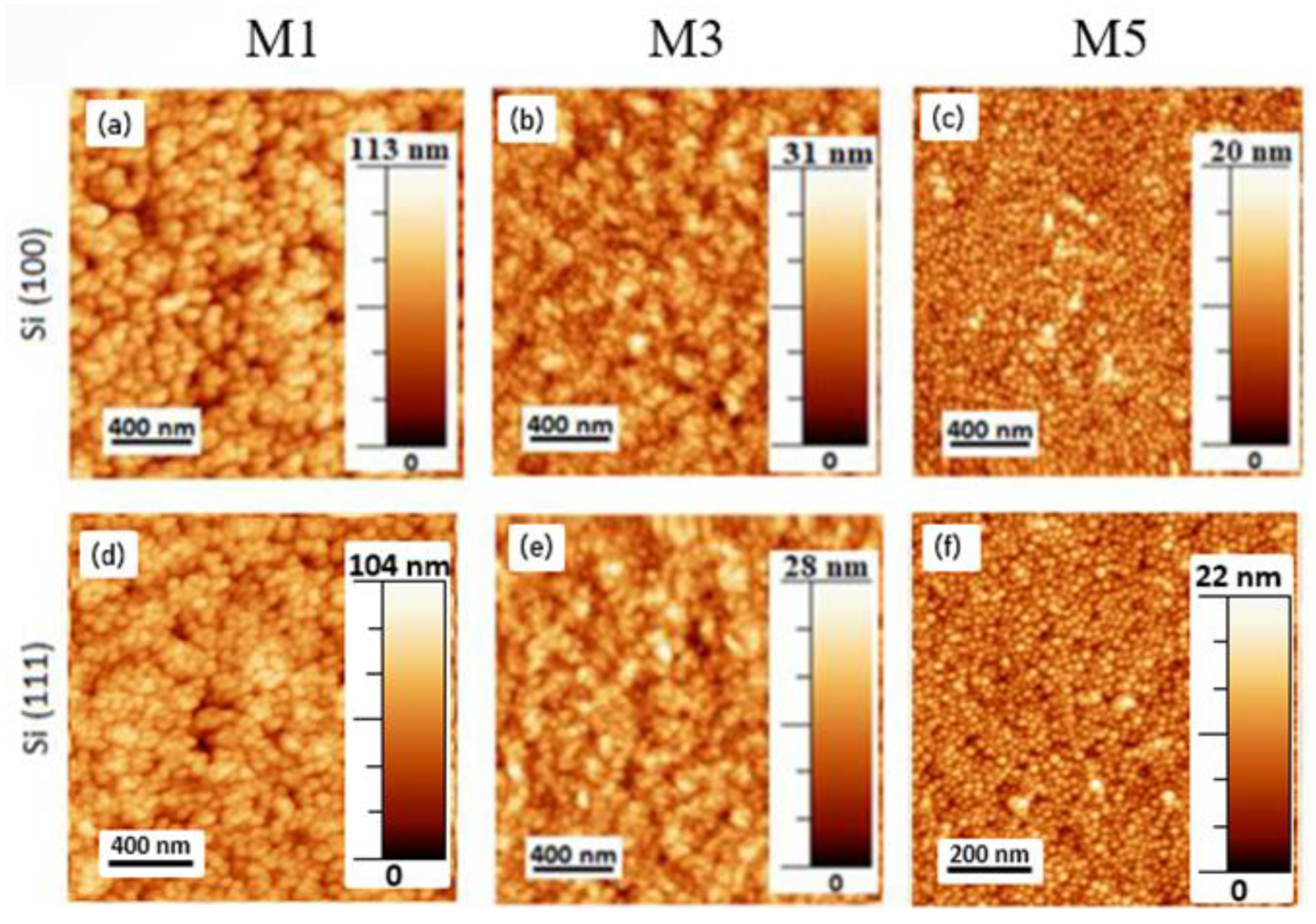
The observed morphological transition was accompanied by a modification of the sample surface roughness. The rms roughness was measured by AFM images scanned in a 2 × 2 μm area (Figure 3). The results showed a surface roughness evolution from 11.5 (Al content x = 0) to 2.5 nm (x ≈ 0.36) for Si(100) and from 13.0 (Al content x = 0) to 2.5 nm (x ≈ 0.36) for Si(111), as summarized in Table 1, and in agreement with previously published results [31]. The roughness remained almost constant for samples with an Al content in the range within x ≈ 0.36–0.42 (see Table 1), and it finally dropped up to ≈2.5 nm for an Al content of ≈50%. This surface roughness reduction was attributed to an increase in the adatom energy and mobility when increasing PAl, in agreement with results obtained in similar AlxIn1-xN-on-Si(100) samples deposited at a higher temperature (550 °C) [27], where the surface roughness was 2.0 and 1.5 nm for x ≈ 0.35 and x ≈ 0.56, respectively.
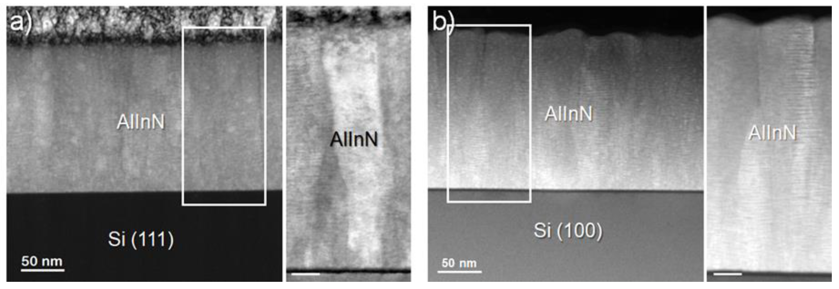
The interface between the AlxIn1−xN and the silicon substrate was studied by transmission electron microscopy (TEM) measurements. Figure 4 shows the cross-sectional TEM images of an AlxIn1−xN (x ≈ 0.36) layer deposited on Si(100) and Si(111), evidencing the epitaxial growth along the c-axis for the two silicon orientations. In both cases, the images reveal the formation of an amorphous layer of ~2.5 nm at the layer/substrate interface (see the inset of both figures), which may have weakened the interactions between phases and reduced the influence of the silicon orientation on the quality of the nitride layer deposited on top. The similar structural quality obtained growing on both substrates was also confirmed by the comparable grain size estimated from STEM images (Figure 5a,b). Thus, the structural quality is conserved even when grown on a cubic substrate, although a clearer boundary between the amorphous interfacial layer and the nitride one was observed in this case.

3.3. Electrical Characterization

The electrical properties of the AlxIn1-xN layers could only be addressed for samples deposited on sapphire substrates, because the silicon conduction masked the layered signal whenever a silicon substrate was used. The values of resistivity, carrier concentration, and mobility were obtained for simultaneously grown layers with an Al content up to 0.32. Samples with higher Al content showed a resistivity above 10 mΩ·cm, making the Hall effect measurement unreliable.
The layer resistivity increased from 0.38 mΩ·cm for InN to 8 mΩ·cm for Al0.32In0.68N, while the carrier concentration decreased from 1.73 × 1021 cm−3 for InN to 2.48 × 1020 cm−3 for Al0.32In0.68N. On the other hand, the values of mobility showed no clear trend, starting with a value of 9.5 cm2/V.s for InN and decreasing to 3.2 cm2/V.s for Al0.32In0.68N with a peak of 11.5 cm2/V.s for Al0.14In0.86N. The values of resistivity and mobility obtained for the Al0.32In0.68N sample are similar to those reported by Liu et al. [38] (1.2 mΩ·cm and 11.4 cm2/V·s, respectively, for a ~90 nm Al0.28In0.72N layer deposited by RF sputtering at 600 °C). The high carrier concentration of the layers is related to the unintentional doping from impurities such as hydrogen or oxygen during growth [32], and it was also observed by Nuñez-Cascajero et al. [26], where similar AlxIn1−xN on sapphire with homogeneous distribution of oxygen were obtained.

3.4. Optical Characterization

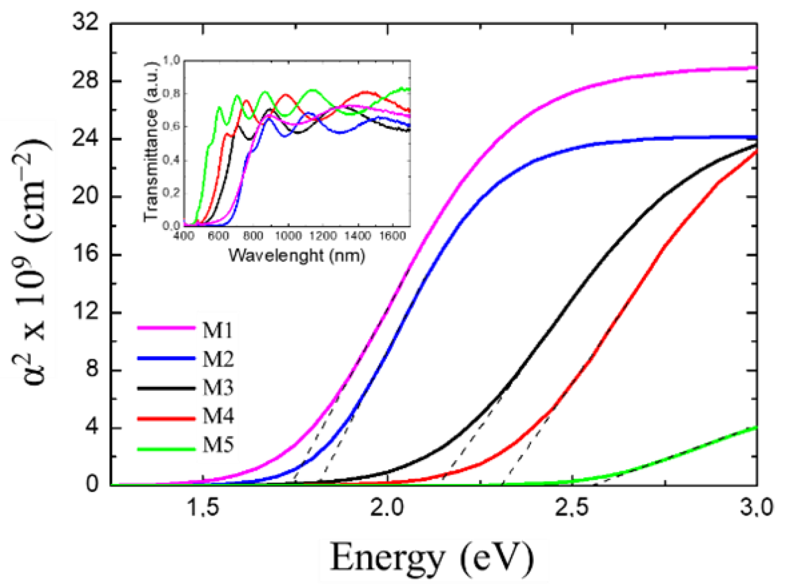
The apparent optical band gap energy of the samples deposited on sapphire was estimated through room-temperature optical transmittance measurements following the procedure described in Ref. [26] (See Table 2 for all optical data). Figure 6 shows the squared absorption used for this estimation, obtained from the transmittance spectra depicted in the inset of the figure for each sample.
As expected, the apparent optical band gap energy blue shifted with the Al mole fraction as following: EgAbs ~ 1.70 eV for InN (M1), 1.80 eV (M2), 2.10 eV (M3), 2.30 eV (M4), and 2.60 eV for Al0.43In0.57N (M5). This blue shift in the optical band gap of the InN, compared with the theoretical of 0.7 eV, was attributed to the high residual carrier concentration of the layer.
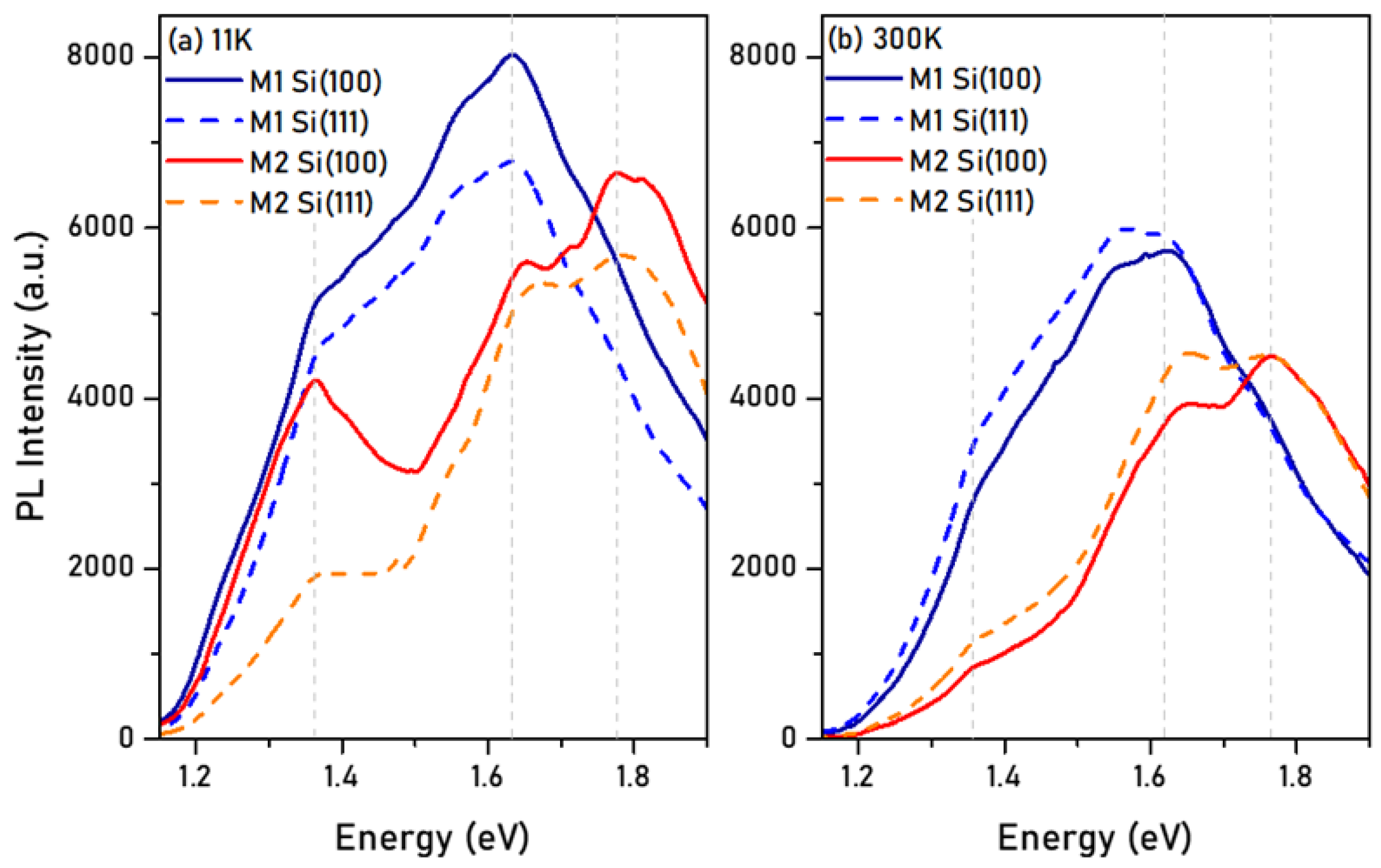
Figure 7 shows the low-(11 K) and room-temperature (300K) PL emission of samples M1 (InN) and M2 (AlxIn1−xN, x—0.12, 0.16), grown on Si(100) and Si(111). No PL emission was observed for AlxIn1−xN layers with higher Al content than 16%, independent of the crystal orientation of the substrate. The results obtained from the analysis of the PL measurements in terms of the main peak emission energy, FWHM, and integrated intensity are summarized in Table 3.
The dominant room-temperature emission energy centered at ≈1.60 and ≈1.80 eV for the M1 (InN) and M2 (AlxIn1−xN, x—0.12, 0.16) samples deposited on both silicon substrates, respectively. The position of the emission energy practically stayed the same, while the intensity decreased when increasing the temperature from 11 to 300 K, as expected. However, the presence of an emission at room temperature was a clear indication of the good crystalline quality of the samples. The FWHM of the PL emission of the samples was similar for both types of substrates, being slightly higher for sample M2, probably due to the alloy disorder present in the AlxIn1−xN layer.
Then, assuming that the band gap energy was similar for the samples grown on Si and sapphire, we could extract an approximate value for the Stokes shift as the difference between the band gap energy obtained from transmission measurements (EgAbs) and the PL emission energy (EPL) at 300 K. The obtained Stokes shift was around ~130 and ~60 meV for InN (M1) and AlxIn1−xN (M2), respectively. These values pointed to a reduced band tail for the AlxIn1−xN samples compared with the InN ones, which could be related to the change in layer morphology (and probably the surrounding of the involved emission centers) when introducing aluminum into the InN binary.
Lastly, comparing each sample on both substrates, they showed a very similar emission shape and integrated intensity, even though the AlxIn1-xN ones had double the layer thickness compared with their InN counterparts. This result pointed to an enhancement of the nonradiative recombination channels due to Al incorporation, which could increase the lattice disorder and defects.

4. Conclusions

AlxIn1−xN films with low-to-mid Al content (x—0–0.50) were deposited via RF sputtering on different substrates, i.e., Si(100) and Si(111), for their comparison. The increase in the Al mole fraction improved the structural and morphological quality of the layers, achieving a minimum FWHM of the (0002) AlxIn1−xN rocking curve of ~2.8° and a minimum rms surface roughness of ~2.5 nm for samples grown on both Si substrates with x—0.49. FESEM images showed a morphological transition from nanocolumnar toward a grain-like compact morphology when aluminum was introduced. Cross-sectional TEM images revealed a ~2.5 nm thick amorphous layer in the interface between the nitride material and the substrate, which could be responsible for the weak coupling between the active layer and the substrate. This finding allows the development of AlxIn1−xN with similar material quality on both silicon substrate orientations.
Hall-effect measurements revealed a carrier concentration above 1020 cm−3 for the AlxIn1-xN layers with x < 0.32, probably induced by the unintentional doping of the material during deposition. Additionally, the AlxIn1-xN layers (x ≤ 0.16) deposited on both Si substrate orientations exhibited similar PL emission in terms of shape, energy, FWHM, and integrated intensity at room temperature, showing a reduction in the PL emission efficiency when introducing the Al compared with the one obtained for InN layers.
In this work, we demonstrated the ability to produce high-quality AlxIn1−xN layers on Si with low-to-mid Al content via RF sputtering regardless of the chosen substrate orientation.

Author Contributions

Investigation, R.B., J.N., M.d.l.M., S.I.M., A.A. and E.M.; Writing—original draft, M.S.; Writing—review & editing, S.V.-F. and F.B.N. All authors have read and agreed to the published version of the manuscript.

Funding

Partial financial support was provided by the projects: NERA (RTI2018-101037-B-I00), SINFOTON2-CM (P2018/NMT-4326), GRISA (CM/JIN/2021-021), and CAM-project (EPU-DPTO/2020/012).

Institutional Review Board Statement

Not applicable.

Informed Consent Statement

Not applicable.

Conflicts of Interest

The authors declare no conflict of interest.

References

  1. Wu, J.; Walukiewicz, W.; Yu, K.M.; Ager, J.; Haller, E.E.; Lu, H.; Schaff, W.J.; Saito, Y.; Nanishi, Y. Unusual properties of the fundamental band gap of InN. Appl. Phys. Lett. 2002, 80, 3967–3969. [Google Scholar] [CrossRef] [Green Version]
  2. Yim, W.M.; Stofko, E.J.; Zanzucchi, P.J.; Pankove, J.I.; Ettenberg, M.; Gilbert, S.L. Epitaxially grown AlN and its optical band gap. J. Appl. Phys. 1973, 44, 292–296. [Google Scholar] [CrossRef]
  3. Lu, N.; Ferguson, I. III-nitrides for energy production: Photovoltaic and thermoelectric applications. Semicond. Sci. Technol. 2013, 28, 074023. [Google Scholar] [CrossRef]
  4. Hums, C.; Bläsing, J.; Dadgar, A.; Diez, A.; Hempel, T.; Christen, J.; Krost, A.; Lorenz, K.; Alves, E. Metal-organic vapor phase epitaxy and properties of AlInN in the whole compositional range. Appl. Phys. Lett. 2007, 90, 022105. [Google Scholar] [CrossRef]
  5. Senda, S.; Jiang, H.; Egawa, T. AlInN-based ultraviolet photodiode grown by metal organic chemical vapor deposition. Appl. Phys. Lett. 2008, 92, 203507. [Google Scholar] [CrossRef]
  6. Yun, L.; Wei, T.; Yan, J.; Liu, Z.; Wang, J.; Li, J. MOCVD epitaxy of InAlN on different templates. J. Semicond. 2011, 32, 093001. [Google Scholar] [CrossRef]
  7. Dinh, D.V.; Hu, N.; Honda, Y.; Amano, H.; Pristovsek, M. Indium icorporation and optical properties of polar, semipolar and nonpolar InAlN. Semicond. Sci. Technol. 2019, 35, 035004. [Google Scholar] [CrossRef]
  8. Wu, Y.-H.; Wong, Y.-Y.; Chen, W.-C.; Tsai, D.-S.; Peng, C.-Y.; Tian, J.-S.; Chang, L.; Chang, E.Y. Indium-rich InAlN films on GaN/sapphire by molecular beam epitaxy. Mater. Res. Express 2014, 1, 015904. [Google Scholar] [CrossRef]
  9. Kamimura, J.; Kouno, T.; Ishizawa, S.; Kikuchi, A.; Kishino, K. Growth of high-In-content InAlN nanocolumns on Si (111) by RF-plasma-assisted molecular-beam epitaxy. J. Cryst. Growth 2007, 300, 160–163. [Google Scholar] [CrossRef]
  10. Bhuiyan, A.G.; Islam, S.; Hashimoto, A. Molecular beam epitaxy of InAlN alloys in the whole compositional range. AIP Adv. 2020, 10, 015053. [Google Scholar] [CrossRef]
  11. Chen, W.-C.; Wu, Y.-H.; Tian, J.-S.; Yen, T.-C.; Lin, P.-Y.; Chen, J.-Y.; Hsiao, C.-N.; Chang, L. Effect of Growth Temperature on Structural Quality of In-Rich InxAl1−xN Alloys on Si (111) Substrate by RF-MOMBE. ISRN Nanomater. 2014, 2014, 1–6. [Google Scholar] [CrossRef]
  12. Yodo, T.; Ando, H.; Nosei, D.; Harada, Y. Growth and characterization of InN heteroepitaxial layers grown on Si substrates by ECR-assisted MBE. Phys. Status Solidi Basic Res. 2001, 228, 21–26. [Google Scholar] [CrossRef]
  13. Afzal, N.; Devarajan, M.; Ibrahim, K. Growth of AlInN films via elemental layers annealing at different temperatures. Mod. Phys. Lett. B 2015, 29, 1550169. [Google Scholar] [CrossRef]
  14. Afzal, N.; Devarajan, M.; Subramani, S.; Ibrahim, K. Structural and surface analysis of AlInN thin films synthesized by elemental stacks annealing. Mater. Res. Express 2014, 1, 026403. [Google Scholar] [CrossRef]
  15. Afzal, N.; Devarajan, M.; Ibrahim, K. Influence of substrate temperature on the growth and properties of reactively sputtered In-rich InAlN films. J. Mater. Sci. Mater. Electron. 2016, 27, 4281–4289. [Google Scholar] [CrossRef]
  16. He, H.; Cao, Y.; Fu, R.; Guo, W.; Huang, Z.; Wang, M.; Huang, C.; Huang, J.; Wang, H. Band gap energy and bowing parameter of In-rich InAlN films grown by magnetron sputtering. Appl. Surf. Sci. 2010, 256, 1812–1816. [Google Scholar] [CrossRef]
  17. Guo, Q.; Okazaki, Y.; Kume, Y.; Tanaka, T.; Nishio, M.; Ogawa, H. Reactive sputter deposition of AlInN thin films. J. Cryst. Growth 2007, 300, 151–154. [Google Scholar] [CrossRef]
  18. Guo, Q.; Yahata, K.; Tanaka, T.; Nishio, M.; Ogawa, H. Growth and characterization of reactive sputtered AlInN films. Phys. Status Solidi 2003, 2533–2536. [Google Scholar] [CrossRef]
  19. Lv, W.; Shen, L.; Liu, J.; Chen, J.; Wu, L.; Qi, D.; Zhang, G.; Li, X. Mechanical properties of single-phase Al1−In N films across the compositional range (0 ≤ x ≤ 0.7) grown by radio-frequency magnetron sputtering. Appl. Surf. Sci. 2019, 504, 144335. [Google Scholar] [CrossRef]
  20. Zhou, Y.; Peng, W.; Li, J.; Liu, Y.; Zhu, X.; Wei, J.; Wang, H.; Zhao, Y. Substrate temperature induced physical property variation of InxAl1−xN alloys prepared on Al2O3 by magnetron sputtering. Vacuum 2020, 179, 109512. [Google Scholar] [CrossRef]
  21. Zhao, Y.; Wang, H.; Li, X.; Li, J.; Shi, Z.; Wu, G.; Zhuang, S.; Yin, C.; Yang, F. Parametric study on the well-oriented growth of InxAl1-xN nanodots by magnetron sputtering. Mater. Sci. Semicond. Process. 2019, 102, 104583. [Google Scholar] [CrossRef]
  22. Afzal, N.; Devarajan, M.; Ibrahim, K. A comparative study on the growth of InAlN films on different substrates. Mater. Sci. Semicond. Process. 2016, 51, 8–14. [Google Scholar] [CrossRef]
  23. He, H.; Cao, Y.; Fu, R.; Wang, H.; Huang, J.; Huang, C.; Wang, M.; Deng, Z. Structure and optical properties of InN and InAlN films grown by rf magnetron sputtering. J. Mater. Sci. Mater. Electron. 2010, 21, 676–681. [Google Scholar] [CrossRef]
  24. Afzal, N.; Devarajan, M.; Ibrahim, K. Synthesis of aluminium indium nitride (AlInN) thin films by stacked elemental layers method. Eur. Phys. J. Appl. Phys. 2014, 67, 10301. [Google Scholar] [CrossRef]
  25. Valdueza-Felip, S.; Núñez-Cascajero, A.; Blasco, R.; Montero, D.; Grenet, L.; de la Mata, M.; Fernández, S.; Marcos, L.R.-D.; Molina, S.I.; Olea, J.; et al. Influence of the AlN interlayer thickness on the photovoltaic properties of in-rich AlInN on Si heterojunctions deposited by RF sputtering. AIP Adv. 2018, 8, 115315. [Google Scholar] [CrossRef] [Green Version]
  26. Núñez-Cascajero, A.; Valdueza-Felip, S.; Monteagudo-Lerma, L.; Monroy, E.; Taylor-Shaw, E.; Martin, R.W.; González-Herráez, M.; Naranjo, F.B. In-rich AlxIn1−xN grown by RF-sputtering on sapphire: From closely-packed columnar to high-surface quality compact layers. J. Phys. D Appl. Phys. 2017, 50, 065101. [Google Scholar] [CrossRef]
  27. Blasco, R.; Valdueza-Felip, S.; Montero, D.; Sun, M.; Olea, J.; Naranjo, F.B. Low-to-Mid Al Content (x = 0–0.56) AlxIn1−x N Layers Deposited on Si(100) by Radio-Frequency Sputtering. Phys. Status Solidi 2020, 257, 1900575. [Google Scholar] [CrossRef]
  28. Núñez-Cascajero, A.; Valdueza-Felip, S.; Blasco, R.; de la Mata, M.; Molina, S.I.; Gonzalez-Herraez, M.; Monroy, E.; Naranjo, F. Quality improvement of AlInN/p-Si heterojunctions with AlN buffer layer deposited by RF-sputtering. J. Alloy. Compd. 2018, 769, 824–830. [Google Scholar] [CrossRef]
  29. Blasco, R.; Núñez-Cascajero, A.; Jiménez-Rodríguez, M.; Montero, D.; Grenet, L.; Olea, J.; Naranjo, F.B.; Valdueza-Felip, S. Influence of the AlInN Thickness on the Photovoltaic Characteristics of AlInN on Si Solar Cells Deposited by RF Sputtering. Phys. Status Solidi 2019, 216, 1800494. [Google Scholar] [CrossRef] [Green Version]
  30. Núñez-Cascajero, A.; Blasco, R.; Naranjo, F.N.; Valdueza-Felip, S. High quality Al0.37In0.63N layers grown at low temperature (<300 °C) by radio-frequency sputtering. Mater. Sci. Semicond. Process. 2019, 100, 8–14. [Google Scholar] [CrossRef]
  31. Núñez-cascajero, A.; Monteagudo-Lerma, L.; Valdueza-Felip, S.; Navío, C.; Monroy, E.; González-Herráez, M.; Naranjo, F.B. Study of high In-content AlInN deposition on p-Si (111) by RF-sputtering. Jpn. J. Appl. Phys. 2016, 55, 05FB07. [Google Scholar] [CrossRef]
  32. Darakchieva, V.; Lorenz, K.; Barradas, N.P.; Alves, E.; Monemar, B.; Schubert, M.; Franco, N.; Hsiao, C.-L.; Chen, L.-C.; Schaff, W.J.; et al. Hydrogen in InN: A ubiquitous phenomenon in molecular beam epitaxy grown material. Appl. Phys. Lett. 2010, 96, 081907. [Google Scholar] [CrossRef] [Green Version]
  33. Darakchieva, V.; Barradas, N.P.; Xie, M.-Y.; Lorenz, K.; Alves, E.; Schubert, M.; Persson, P.; Giuliani, F.; Munnik, F.; Hsiao, C.-L.; et al. Role of impurities and dislocations for the unintentional n-type conductivity in InN. Phys. B Condens. Matter 2009, 404, 4476–4481. [Google Scholar] [CrossRef]
  34. Butcher, K.; Tansley, T. InN, latest development and a review of the band-gap controversy. Superlattices Microstruct. 2005, 38, 1–37. [Google Scholar] [CrossRef]
  35. Bashir, U.; Hassan, Z.; Ahmed, N.M. A comparative study of InN growth on quartz, silicon, C-sapphire and bulk GaN substrates by RF magnetron sputtering. J. Mater. Sci. Mater. Electron. 2017, 28, 9228–9236. [Google Scholar] [CrossRef]
  36. Han, Q.; Duan, C.; Du, G.; Shi, W.; Ji, L. Magnetron Sputter Epitaxy and Characterization of Wurtzite AlInN on Si(111) Substrates. J. Electron. Mater. 2010, 39, 489–493. [Google Scholar] [CrossRef]
  37. Dong, C.J.; Xu, M.; Chen, Q.Y.; Liu, F.S.; Zhou, H.P.; Wei, Y.; Ji, H.X. Growth of well-oriented AlxIn1−xN films by sputtering at low temperature. J. Alloy. Compd. 2009, 479, 812–815. [Google Scholar] [CrossRef]
  38. Liu, H.F.; Tan, C.C.; Dalapati, G.K.; Chi, D.Z. Magnetron-sputter deposition of high-indium-content n-AlInN thin film on p-Si(001) substrate for photovoltaic applications. J. Appl. Phys. 2012, 112, 063114. [Google Scholar] [CrossRef]
  39. Von, L.V. Die Konstitution der Mischkristalle und die Raumfullung der Atome. Z. Phys. 1921, 5, 17–26. [Google Scholar]
Figure 1. The 2θ/ω scans of the AlxIn1−xN layers deposited on (a) Si(100) and (b) Si(111) for different PAl. The only reflections assigned to AlxIn1−xN were (0002) and (0004). The rest of the reflections were assigned to the substrates.
Materials 15 07373 g001
Figure 2. FESEM images of AlxIn1−xN samples (a) M1, (b) M3, and (c) M5 on Si(100) (left) and Si(111) (right).
Materials 15 07373 g002
Figure 3. AFM images with a scanning area of 2 × 2 μm of InN and AlxIn1−xN samples with PAl = 0, 150, and 225 W grown on Si(100) (ac) and Si(111) (df).
Materials 15 07373 g003
Figure 4. HRTEM images of Al0.36In0.64N samples grown on (a) Si(100) and (b) Si(111), along with magnified details of the interphase (right side). Insets show the epitaxial relationship between the layer and substrate.
Materials 15 07373 g004
Figure 5. HRTEM images of Al0.36In0.64N samples grown on (a) Si(100) and (b) Si(111) show a similar grain size on both substrates. Scale bar at the magnified details is 20 nm.
Materials 15 07373 g005
Figure 6. Squared absorption coefficient α2 as a function of the energy extracted from the sigmoidal approximation of the AlxIn1−xN layers grown on sapphire. Dashed lines are the linear fits used to estimate the apparent optical band gap energy of the samples EgAbs. Inset: transmittance spectra vs. wavelength of the same samples M1–M5.
Materials 15 07373 g006
Figure 7. (a) Low-temperature (11K) and (b) room-temperature (300 K) PL emission of AlxIn1−xN layers deposited on Si(100) and Si(111). For x > 0.16, no PL emission was observed.
Materials 15 07373 g007
Table 1. Summary of the deposition parameters and the structural and morphological analysis of AlxIn1−xN on Si(100) and Si(111): c-axis parameter and Al mole fraction x extracted from HRXRD, layer thickness estimated from FESEM, and rms surface roughness measured by AFM.
SampleSubstratePAl (W)c (Å)Al Mole Fraction xFWHM
Rocking Curve (°)
Thickness 1 (nm)Deposition Rate 2 (nm/h)Rms Surface Roughness 3 (nm)
M1Si(100)05.7304.639013011.5
M21005.610.122.47901609.5
M31505.450.356.26501603.5
M41755.420.403.26201553.5
M52255.360.482.89102302.5
M1Si(111)05.7304.738012513.0
M21005.590.162.97801608.0
M31505.440.366.16401603.5
M41755.400.423.16301603.5
M52255.350.492.85851502.5
1 Standard error of ±30 nm. 2 Standard error of ±15 nm/h. 3 Standard error of ±0.3 nm.
Table 2. Summary of the optical transmittance characterization at room temperature: apparent optical band gap energy (EgAbs), absorption band edge broadening (ΔE), and linear absorption well above the band gap ( α 0 ) of the samples under study.
SampleAl Mole Fraction x α 0   × 10 4   c m 2 E g A b s e V   1 Δ E m e V   2
M1017.21.70160
M20.1220.31.80120
M30.3518.42.10210
M40.4018.32.30210
M50.4810.02.60180
1 Standard error of ±0.03 eV. 2 Standard error of ±10 meV.
Table 3. Summary of the analysis of the PL measurements at 11 K and 300 K of InN (M1) and AlxIn1−xN (M2) on Si(100) and Si(111).
SampleTemperature (K)SubstrateMain Peak Emission Energy 1 (eV)FWHM 2 (meV)Integrated Intensity 3 (a.u.)
M111Si(100)1.605604500
Si(111)1.605153600
300Si(100)1.604602750
Si(111)1.604652920
M211Si(100)1.805653750
Si(111)1.804803100
300Si(100)1.805002250
Si(111)1.754902400
1 Standard error of ±0.05 eV. 2 Standard error of ±5 meV. 3 Standard error of ±10.
Publisher’s Note: MDPI stays neutral with regard to jurisdictional claims in published maps and institutional affiliations.