Article

Effect of Pretreatment with Acids on the N-Functionalization of Carbon Nanofibers Using Melamine

by
Tatyana A. Maksimova
1,
Ilya V. Mishakov
1,
Yury I. Bauman
1,
Artem B. Ayupov
1,2,
Maksim S. Mel’gunov
1,2,
Aleksey M. Dmitrachkov
1,2,
Anna V. Nartova
1,2,
Vladimir O. Stoyanovskii
1 and
Aleksey A. Vedyagin
1,*
1
Boreskov Institute of Catalysis, 630090 Novosibirsk, Russia
2
Department of Natural Sciences, Novosibirsk State University, Pirogova Str. 2, 630090 Novosibirsk, Russia
*
Author to whom correspondence should be addressed.
Materials 2022, 15(22), 8239; https://doi.org/10.3390/ma15228239
Submission received: 1 October 2022 / Revised: 11 November 2022 / Accepted: 17 November 2022 / Published: 20 November 2022
(This article belongs to the Special Issue Advanced Materials in Catalysis and Adsorption)

Abstract

:
Nowadays, N-functionalized carbon nanomaterials attract a growing interest. The use of melamine as a functionalizing agent looks prospective from environmental and cost points of view. Moreover, the melamine molecule contains a high amount of nitrogen with an atomic ratio C/N of 1/2. In present work, the initial carbon nanofibers (CNFs) were synthesized via catalytic pyrolysis of ethylene over microdispersed Ni–Cu alloy. The CNF materials were pretreated with 12% hydrochloric acid or with a mixture of concentrated nitric and sulfuric acids, which allowed etching of the metals from the fibers and oxidizing of the fibers’ surface. Finally, the CNFs were N-functionalized via their impregnation with a melamine solution and thermolysis in an inert atmosphere. According to the microscopic data, the initial structure of the CNFs remained the same after the pretreatment and post-functionalization procedures. At the same time, the surface of the N-functionalized CNFs became more defective. The textural properties of the materials were also affected. In the case of the oxidative treatment with a mixture of acids, the highest content of the surface oxygen of 11.8% was registered by X-ray photoelectron spectroscopy. The amount of nitrogen introduced during the post-functionalization of CNFs with melamine increased from 1.4 to 4.3%. Along with this, the surface oxygen concentration diminished to 6.4%.

1. Introduction

In recent decades, researchers have paid special attention to the improvement of methods for the introduction of various heteroatoms into the structure of carbon materials (CMs). The growing interest in this research field was due to the fact that heteroatoms introduced into CM structures noticeably change the properties of the CMs and widen the areas of their application [1,2,3]. For instance, nitrogen-containing CMs (N-CMs) are widely used in production of supercapacitors [4,5,6,7,8,9,10,11,12,13] and in catalysis (as catalysts or catalysts’ supports) [14,15,16,17,18,19,20] as well as in biomedicine [21] and even in criminalistics [22].
All the approaches to prepare N-doped CMs can be classified onto two groups: (i) one-pot functionalization, where nitrogen is introduced at the stage of the CM’s synthesis and (ii) post-functionalization, where preliminarily prepared CMs are chemically modified with nitrogen. The one-pot functionalization considers the preparation of N-CMs via a simultaneous pyrolysis or thermal catalytic decomposition of precursors serving as carbon and nitrogen sources [7,8,10,21,23,24,25,26,27,28]. Often, one substrate containing both carbon and nitrogen atoms can be chosen as such a precursor. In the case of post-functionalization, previously prepared (or purchased from a supplier) CMs are treated with some N-containing reagents. This results in bonding of the N-containing functional groups to the CM’s surface or in embedding of nitrogen atoms into the near-surface carbon structure [4,5,6,9,12,14,15,16,17,20,29,30,31,32,33,34,35,36,37]. The following N-containing compounds are usually used for the functionalization of CMs: ammonia [9,12,29,30,34], aniline in a mixture with ammonium persulphate [32], 3-hydroxyaniline [23], acetonitrile [24], glucosamine hydrochloride [31], dicyandiamide [18], melamine [4,6,7,8,9,10,11,12,14,15,16,17,18,19,20,22,23,37], urea [4,9,16,18,21], nitrogen (II) oxide [12], pyridine [23,36], pyrrole [35,38]; tiourea [20], 1,10-phenantroline [36], and ethylene diamine [13,33]. Among them, melamine, due to its high nitrogen content (atomic ratio C/N = 1/2), relative non-toxicity, and cheapness, is more preferable.
On the other hand, carbon nanofibers (CNFs) represent an important class of CMs with unique properties [39]. Therefore, the search for an appropriate method for their controllable synthesis and N-functionalization is an actual direction in modern materials sciences. In the present work, the synthesis of N-functionalized carbon nanofibers (N-CNFs) was performed via the post-functionalization route using melamine as a precursor. The initial CNF samples were prepared by the process of catalytic chemical vapor deposition (CCVD) of ethylene at 550 °C over the microdispersed Ni–Cu alloy (12 wt% Cu) obtained by the method of mechanochemical alloying of metals [40]. The CCVD process starts with a spontaneous disintegration of the bulk Ni–Cu alloy under the action of carbon erosion. This leads to the formation of dispersed active particles catalyzing the growth of the morphologically uniform carbon filaments of submicron diameter [27,40,41,42]. The subsequent acidic treatment of the thus-obtained CNFs results in a complete elimination of mineral impurities such as metallic particles of the catalyst, since no oxide supports (silica, alumina, etc.) were used in the composition of initial catalyst.
Among the diverse and ever-growing areas of practical application, the N-functionalized carbon nanomaterials attract attention in the field of heterogeneous catalysis. N-doped CNTs and CNFs are now considered as prospective substrates for supported metal catalysts. The metallic clusters (or single atoms) can be stabilized in a highly dispersed state by their anchoring at the surface N-sites [14,15,43]. For instance, the catalysts based on N-doped carbon nanomaterials can be effectively used in such processes as hydrodechlorination [36,44,45], selective hydrogenation reactions [46,47,48], formic-acid decomposition to produce hydrogen [49,50], and reversible (de)hydrogenation of liquid organic hydrogen carriers (LOHCs) [51,52,53]. In the latter methods, catalysts assist both to absorb hydrogen during the hydrogenation of unsaturated bonds of a substrate and to release stored hydrogen via catalytic dehydrogenation (reverse reaction). Thus, the development of a simple, versatile, and cost-effective technique for the N-functionalization of CNMs remains of particular interest.
The aim of the present study was to investigate the effect of the preliminary acidic treatment of CNFs on the characteristics of the N-CNF samples obtained by the post-functionalization of the former CNFs with melamine. The CNFs were treated in two regimes: mild washing out from the catalyst using hydrochloric acid and oxidative treatment in a mixture of concentrated sulfuric and nitric acids. The second regime allows not only washing out the catalyst’s particles but oxidizing of the CNF surface as well [4,29,30,35,54,55,56]. The morphology, structure, and chemical composition of the N-functionalized CNF samples were examined by a number of characterization techniques, including electron microscopy, Raman spectroscopy, and X-ray photoelectron spectroscopy.

2. Materials and Methods

2.1. Chemicals and Materials

Nickel powder (PNK-UT3) and copper powder (PMS-1) used to synthesize the Ni–Cu catalyst were purchased from RusRedMet (Saint-Petersburg, Russia) and NMK-Ural (Yekaterinburg, Russia), respectively. High-purity ethylene (Nizhnekamskneftekhim, Nizhnekamsk, Russia) and high-purity hydrogen (GasProduct, Yekaterinburg, Russia) were used to produce the initial carbon nanofibers. Hydrochloric acid (ultrapure), nitric acid (ultrapure), and sulfuric acid (ultrapure) used for the pretreatment procedures were purchased from SigmaTek LLC (Khimki, Russia). Melamine (Shanxi Fenghe Melamine Co., Yuncheng, China) was used as a nitrogen source for the post-functionalization.

2.2. Synthesis of the Catalyst

The Ni–Cu catalyst was prepared by a mechanochemical alloying of metal powders using an Activator-2S planetary mill (Activator LLC, Novosibirsk, Russia), as described elsewhere [40,57]. Initially, nickel and copper powders were premixed in a weight ratio of Ni/Cu = 88/12. Then, 1 wt% of recently prepared CNF was added to the mixture. This was required to accelerate the carbon erosion stage at the beginning of the CCVD process. A specimen of this mixture (10 g) along with grinding balls (340 g; stainless steel; 5 mm in diameter) was loaded into stainless-steel bowls (250 mL in volume). The rotation frequency of the bowls and the platform was controlled using a VF-S15 industrial frequency inverter (Toshiba Schneider Inverter Corp., Nagoya, Japan). To avoid overheating, the bowls were water-cooled. The acceleration of the grinding balls was 780 m/c2 (~80 G). The mechanochemical alloying was performed for 5 min. Finally, the bowls were unloaded in air, and the product was separated from the grinding balls and weighed.

2.3. Synthesis, Pretreatment and N-Functionalization of CNFs

Initial carbon nanofibers (labeled as cat/CNF, see Table 1) were synthesized via CCVD, as described elsewhere [40]. A specimen of the Ni–Cu catalyst (125 mg) was place into a horizontal quartz tubular reactor installed inside an XD-1200NT high-temperature furnace (Zhengzhou Brother Furnace Co., Zhengzhou, China). The reactor was fed with an argon flow and heated up to 550 °C with a heating rate of 10 °C/min. Then, a reaction mixture composed of ethylene (25 L/h), hydrogen (10 L/h), and argon (20 L/h) was passed through the reactor. The CCVD process was performed at 550 °C for 1 h. The carbon yield was ~110 gCNF/gcat.
Pretreatment of the cat/CNF sample in hydrochloric acid (labeled as ha-CNF, see Table 1) was carried out by soaking it in an aqueous solution of HCl (200 mL of concentrated HCl mixed with 400 mL of distilled water) for 1 day at room temperature. Then, the sample was washed with distilled water on a glass filter until the pH value of the rinse water was neutral.
Oxidative pretreatment of the cat/CNF samples in a mixture of sulfuric and nitric acids (labeled as ox-CNF, see Table 1) was performed on a water bath at 60 °C for 2 h. The cat/CNF sample was placed into a flask along with 150 mL of distilled water, 100 mL of concentrated HNO3, and 100 mL of concentrated H2SO4. Finally, the sample was washed with distilled water on a glass filter until the pH value of the rinse water was neutral.
Post-functionalization of the ha-CNF and ox-CNF samples with melamine (labeled as N/ha-CNF and N/ox-CNF, respectively, see Table 1) was performed as follows. A specimen (1 g) of the ha-CNF or ox-CNF sample was placed into a cylindrical vessel with 0.476 g of melamine dissolved in 20 mL of distilled water in a water bath at 60 °C. The mixture was maintained for 1.5 h and then dried in a drying oven at 150 °C. The dried sample was placed into a muffle, slowly heated up to 400 °C during 1 h, and calcined at this temperature for another 1 h.

2.4. Characterization of the Samples

The N2 adsorption/desorption isotherms were recorded at 77 K using an Autosorb-6B-Kr automated adsorption analyzer (Quantachrome Instruments, Boynton Beach, FL, USA). In order to remove the adsorbed moisture and other impurities, before the measurements, a specimen (~150 mg) of each sample was treated in a vacuum (1 Pa) at 250 °C for 20 h. The characteristics of the porous structure were calculated using the ASWin 2.02 software package (Quantachrome Instruments, Boynton Beach, FL, USA). The specific surface area (SSA) values were obtained in accordance with a MA-BET approach described elsewhere [58]. To calculate the outer SSA of the CNF samples, a method of αS-curves [59] was applied. An adsorption isotherm for Cabot-BP 280 was used as a reference equation [60]. The pore size distribution was evaluated by a quenched solid density functional theory (QSDFT) method using an integrated model with the following parameters: the adsorbate was nitrogen at 77 K, the pores were slotted, the material was carbon, and the calculation was applied to the adsorption branch of the isotherm.
Scanning electron microscopy (SEM, JEOL, Tokyo, Japan) studies of CNFs were performed using a JSM-6460 electron microscope (JEOL, Tokyo, Japan) at a magnification of 1000–100,000×. The morphology of CNFs was examined by transmission electron microscopy (TEM, Hitachi High-Technologies Corp., Tokyo, Japan) using an Hitachi HT7700 TEM (Hitachi High-Technologies Corp., Tokyo, Japan) working at an acceleration voltage of 100 kV and equipped with a W source.
Raman spectra of CNFs were registered on a Horiba Jobin Yvon LabRAM HR UV-VIS-NIR Evolution Raman spectrometer (Horiba, Kyoto, Japan) equipped with an Olympus BX41 microscope (Olympus Corp., Tokyo, Japan) and a 514.5 nm line Ar-ion laser. To avoid thermal decomposition of the CNF samples, the power of light focused in a spot with a diameter of ~2 μm did not exceed 0.8 mW.
The X-ray photoelectron spectroscopy (XPS) experiments were performed using a SPECS spectrometer (SPECS Surface Nano Analysis GmbH, Berlin, Germany) equipped with a hemispherical PHOIBOS-150-MCD-9 analyzer (SPECS Surface Nano Analysis GmbH, Berlin, Germany). The non-monochromatic MgKα radiation (hν = 1253.6 eV) at 200 W and monochromatic AlKα (hν = 1486.7 eV) at 150 W were used for the primary excitation. The spectrometer was calibrated using the peaks Au4f7/2 (84.0 eV) and Cu2p3/2 (932.7 eV) attributed to metallic gold and copper foils [61]. The samples were fixed on a holder with 3 M double-sided adhesive copper conducting tape. Peak 4.1 XPS software was applied for spectral analysis and data processing. In order to determine the binding energy values and the areas of XPS peaks, a Shirley background was subtracted. The XPS spectra were fitted with Gaussian–Lorentzian functions for each XPS region. The atomic ratios of elements were calculated from the integral photoelectron peak intensities corrected by the corresponding relative atomic sensitivity factors [61] and the transmission function of the analyzer.

3. Results and Discussion

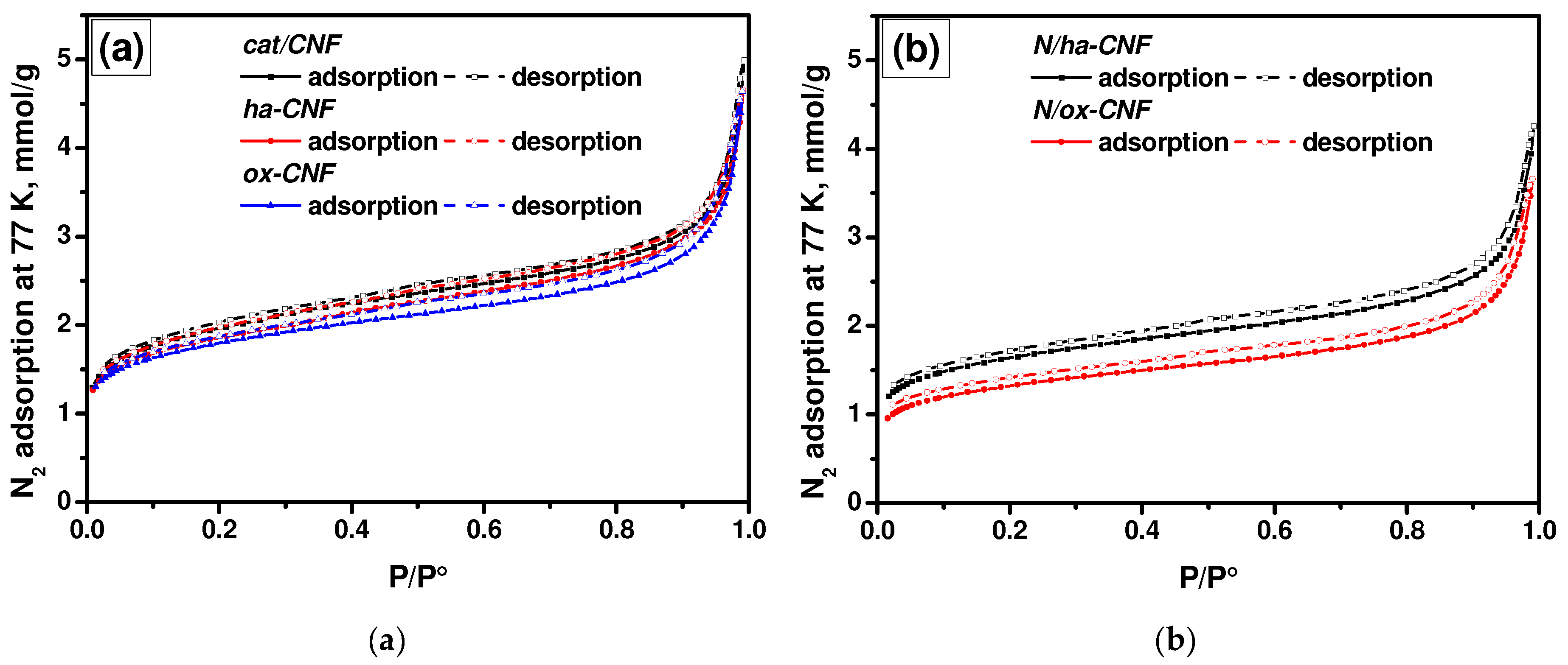
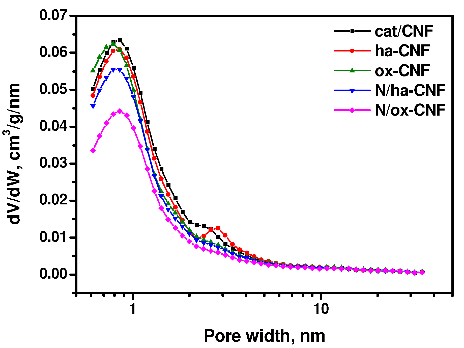
3.1. Textural Properties of CNFs

It is well known that any modification or functionalization of the surface of carbon materials should affect their textural properties. To follow such changes, the low-temperature nitrogen adsorption/desorption technique was applied. The obtained adsorption/desorption isotherms for the CNF samples are shown in Figure 1. The shape of the isotherms indicates the presence of large micropores and small mesopores in all studied CNFs. According to IUPAC classification [62], the isotherms are close to Type I(b). They exhibit a narrow hysteresis loop with a shape close to Types H3 or H4. The adsorption and desorption branches do not connect with each other until the relative pressure value reaches 0.025, thus indicating the non-equilibrium character of adsorption on these samples, which can be explained by the swelling of carbon materials. Apparently, the desorption branch is not equilibrium. Therefore, the adsorption branch was used for the further analysis.
The main characteristics of the porous structure of CNFs are summarized in Table 2. As seen from the presented data, the pretreatment and post-functionalization procedures resulted in a decrease in both the SSA and the total pore volume. The average pore diameter, calculated as 4V/A, where V is the total pore volume and A is the specific surface area, had changed insignificantly. It should be also mentioned that the effect of the post-functionalization with melamine on the textural characteristics of CNFs was more noticeable than the effect of their pretreatment with acids.
The calculation results for the relative pressure region of 0.5–0.9 of the adsorption branch in comparison with the corresponding data of the QSDFT method are presented in Table 3. As recently reported [63], the comparative method can be used to calculate the SSA of the rough micropores. Comparing the presented characteristics, it can be supposed that the method of αS-curves allows the volume of inner pores located inside CNFs to be obtained. Indeed, the values of pore volumes estimated by the αS-curves method were close to those calculated by the QSDFT method for the pores less than 2 nm. Therefore, the value of 2 nm seems to be a border value of width for pores located inside and outside the fibers. Almost all the studied samples, except N/ox-CNF, had similar values for the volume of micropores with a diameter < 2 nm to those calculated by the QSDFT method.
The pore size distributions calculated by the QSDFT method are shown in Figure 2. As seen, all the samples were characterized by the presence of micropores of ~0.8 nm in width. The samples cat/CNF and ha-CNF also contained small mesopores of 2–3 nm in width. It is evident that the post-functionalization with melamine changed the pore size distribution. Thus, the number of pores of 0.8 nm in size decreased noticeably. It is interesting to note that the pretreatment with hydrochloric acid led to a slight shift of the distribution peak at ~2 nm towards higher sizes without a significant change in its value.
In general, each of modification procedures significantly affected the textural characteristics of CNFs. The main tendencies are a decrease in the contribution of small mesopores and an appearance of macropores with a distribution maximum at ~100 nm.

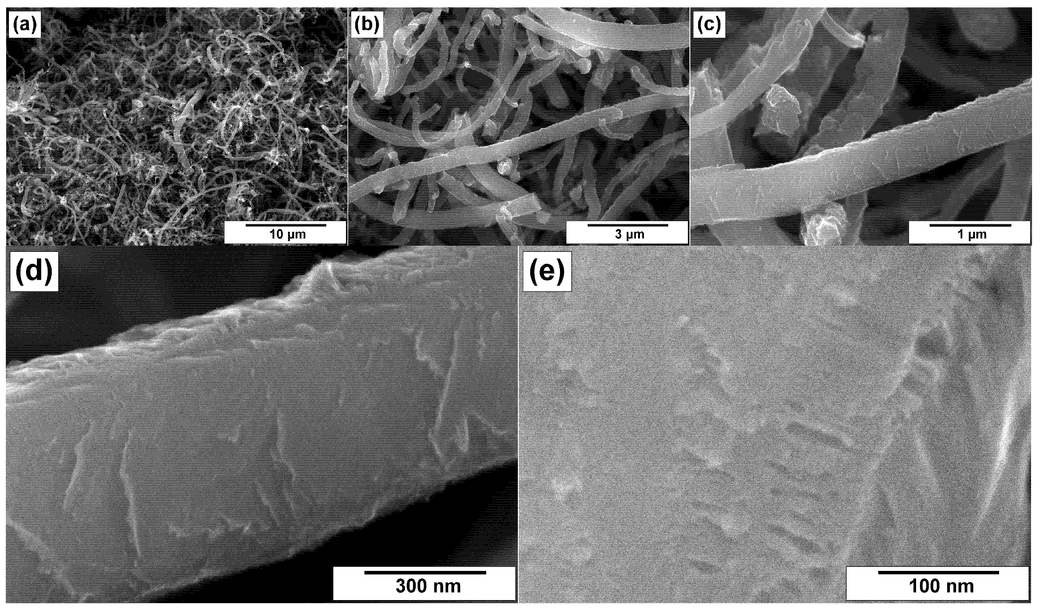
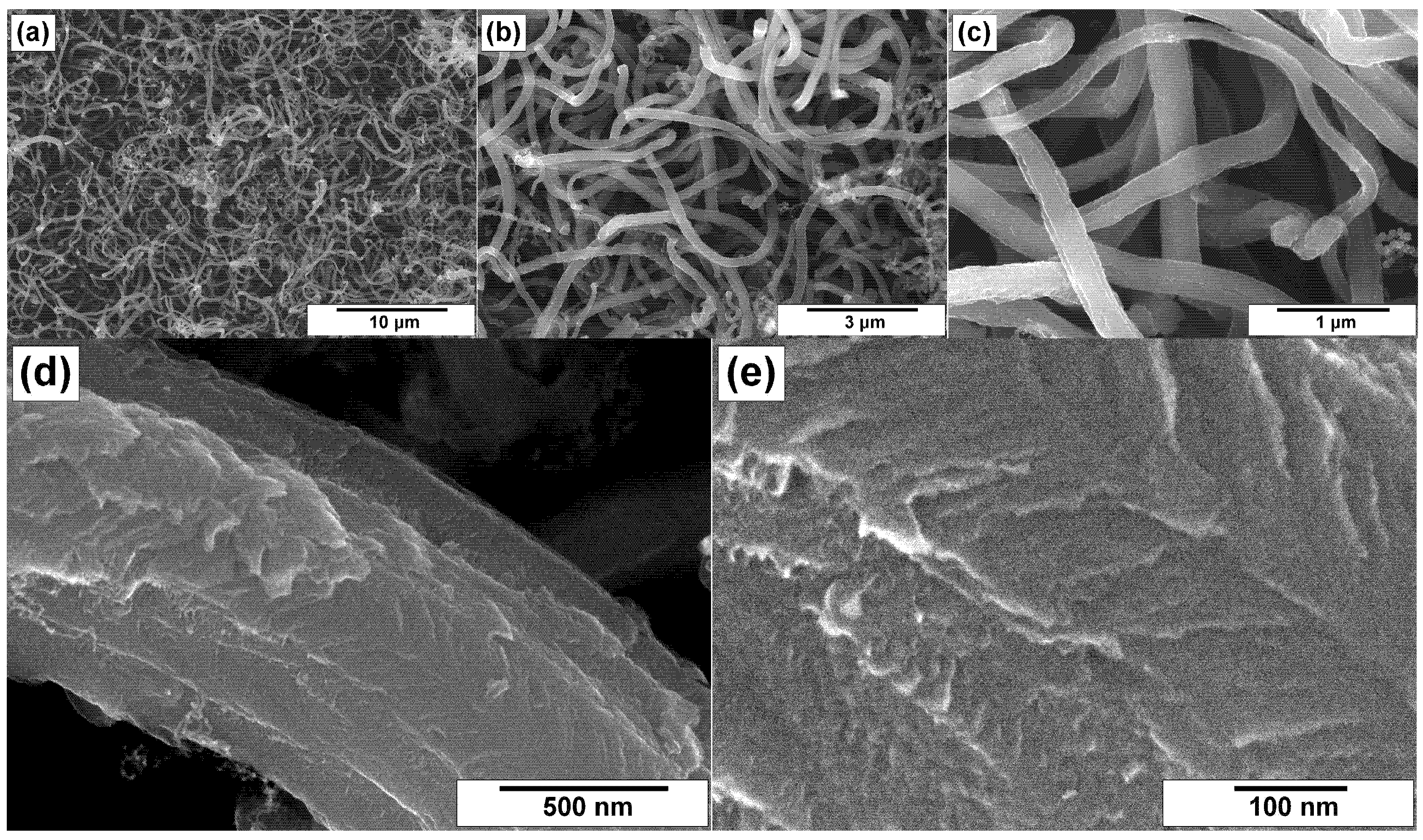
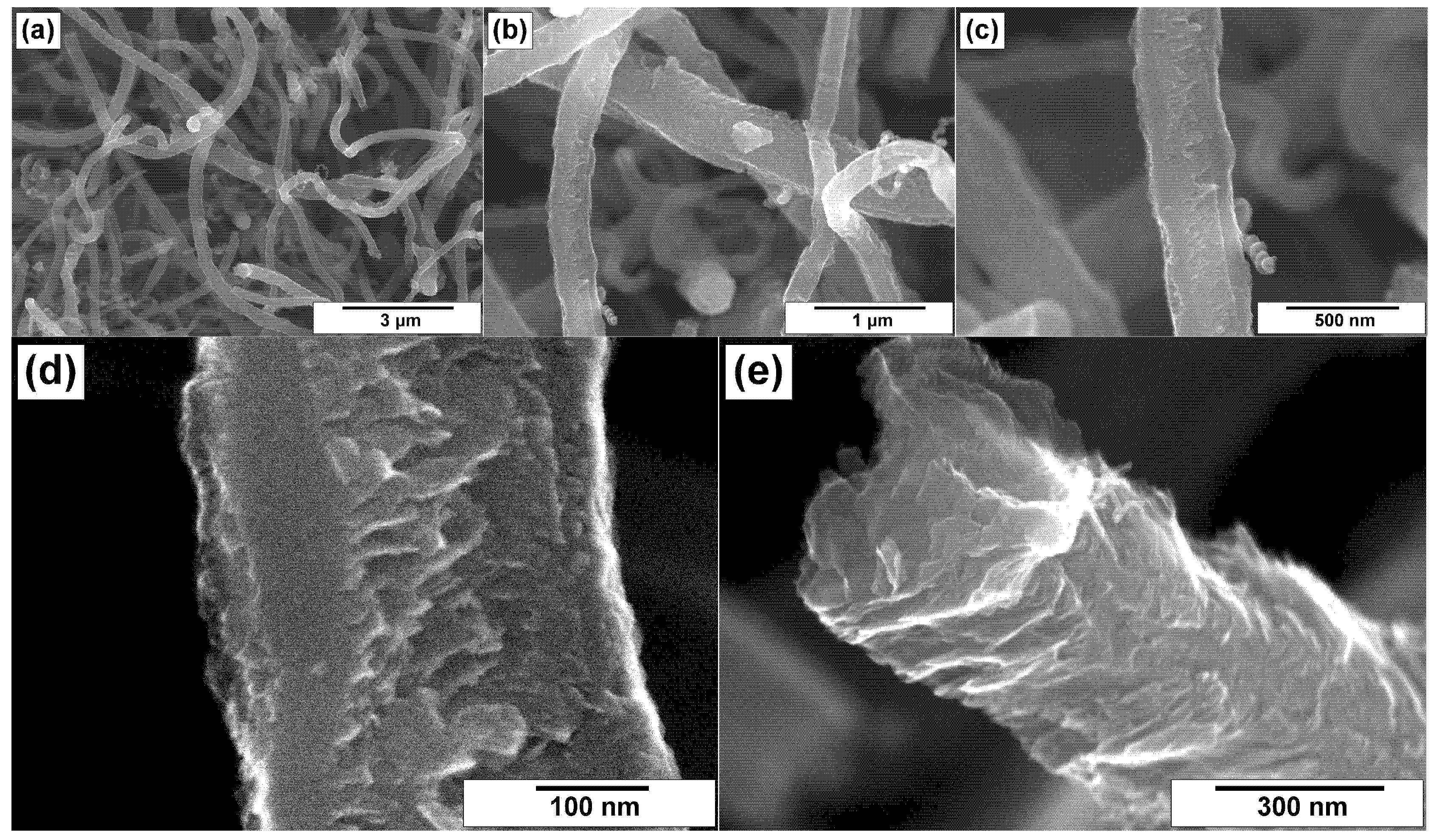
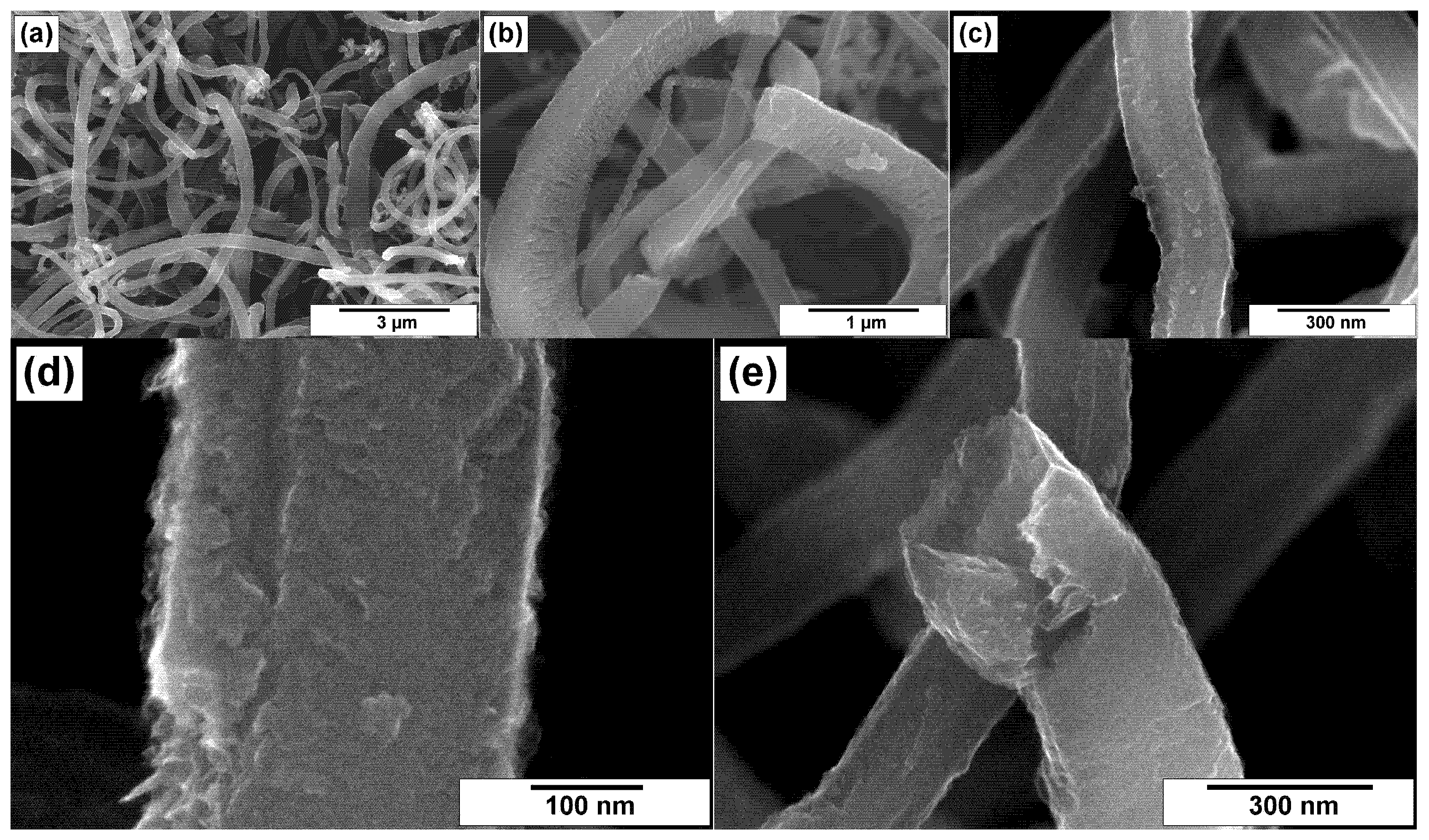
3.2. SEM Characterization of CNFs

The modified CNF samples were explored by the SEM technique. Figure 3 and Figure 4 demonstrate the microscopic images for CNFs treated in hydrochloric acid (ha-CNF) and post-functionalized with melamine (N/ha-CNF), respectively. As seen, the ha-CNF sample before the post-functionalization (Figure 3) possessed a fibrous architecture represented by the assemblage of carbon nanofibers. The diameter of the carbon filaments was varied in a range of 100–500 nm. It should be noted that this parameter is defined by the size of the active Ni–Cu particles, catalyzing the growth of CNFs. The images show that all the fibers were of submicron diameter. This is related to the catalyst’s formation process. During the first minutes of interaction with ethylene, the microdispersed Ni–Cu alloy used as a catalyst’s precursor undergoes a rapid disintegration under the action of carbon erosion [40,41,42]. Such a disintegration of the alloy results in the formation of active particles responsible for the growth of CNFs. It is worth noting that the carbon erosion process predetermines, at earlier stages, the formation of a very fluffy carbon product. The carbon filaments within this product do not tangle or form dense agglomerates.
The individual fibers and their fragments are shown in Figure 3d,e. As seen, the fibers are characterized by a relatively dense packing with a few slit-like pores. The mutual orientation of graphene layers defines the following structural types of CNFs: the stacked “pile of plates” structure and the coaxial cones “fishbone” structure [64,65]. The surface of CNF looks rough.
Comparing the ha-CNF samples before (Figure 3) and after the post-functionalization (Figure 4), it can be seen that this procedure (the impregnation with a solution of melamine followed by the calcination at 400 °C) did not practically affect the morphology and the structure of CNFs and did not lead to their destruction.
On the contrary, pretreatment by heating in a mixture of sulfuric and nitric acids resulted in loosening of the outer surface of CNFs, thus making them more rough (Figure 5c,d). Figure 5e illustrates the packing character of the flakes within the fiber’s body with eliminated metal particle of the catalyst. Nevertheless, the structure integrity of initial CNFs was not broken during such a drastic conditions of the oxidative treatment.
The influence of the subsequent N-functionalization of the ox-CNF sample on its secondary structure is shown in Figure 6. The fibrous structure of the carbon material remained mainly the same. At the same time, the surface of fibers was maximally loosened (Figure 6c,d). Despite no sufficient changes in the secondary structure being observed, many splits, cleaved facets, and cracks are clearly seen.

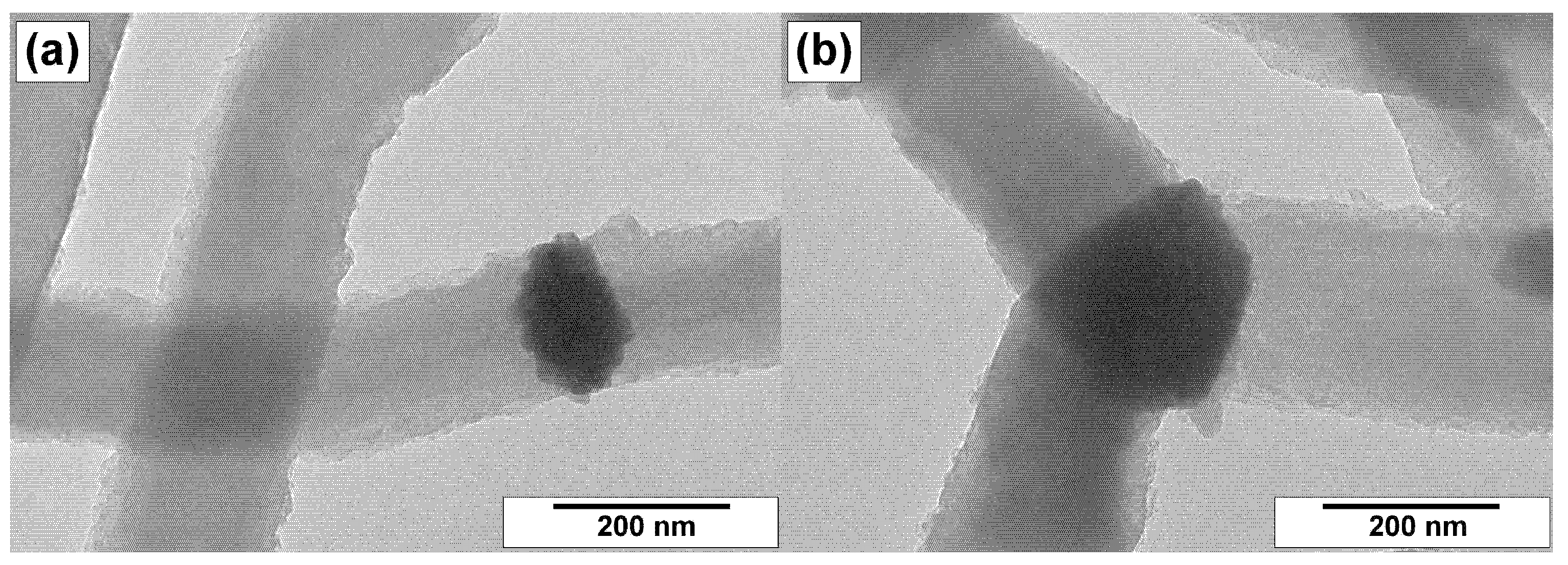
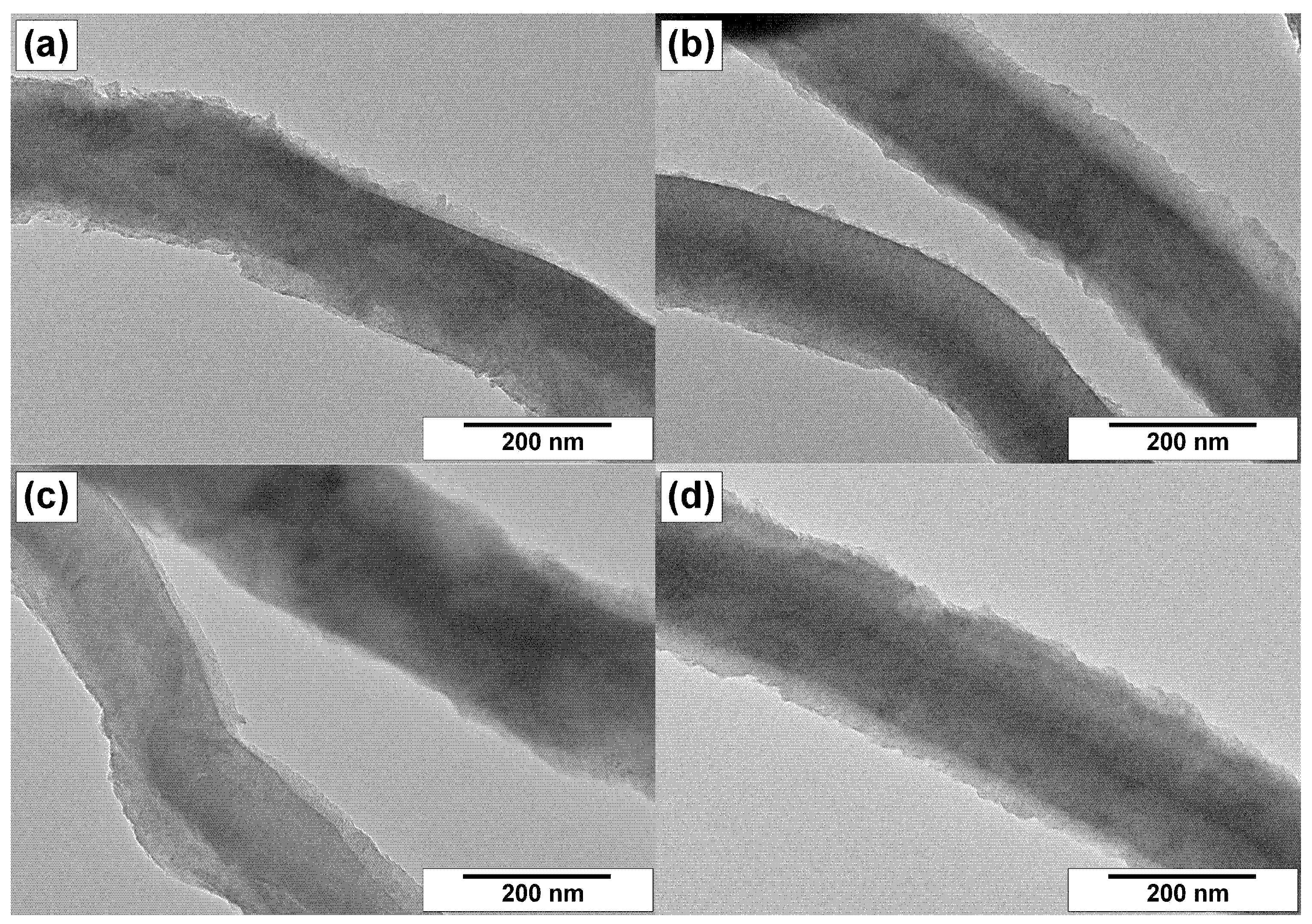
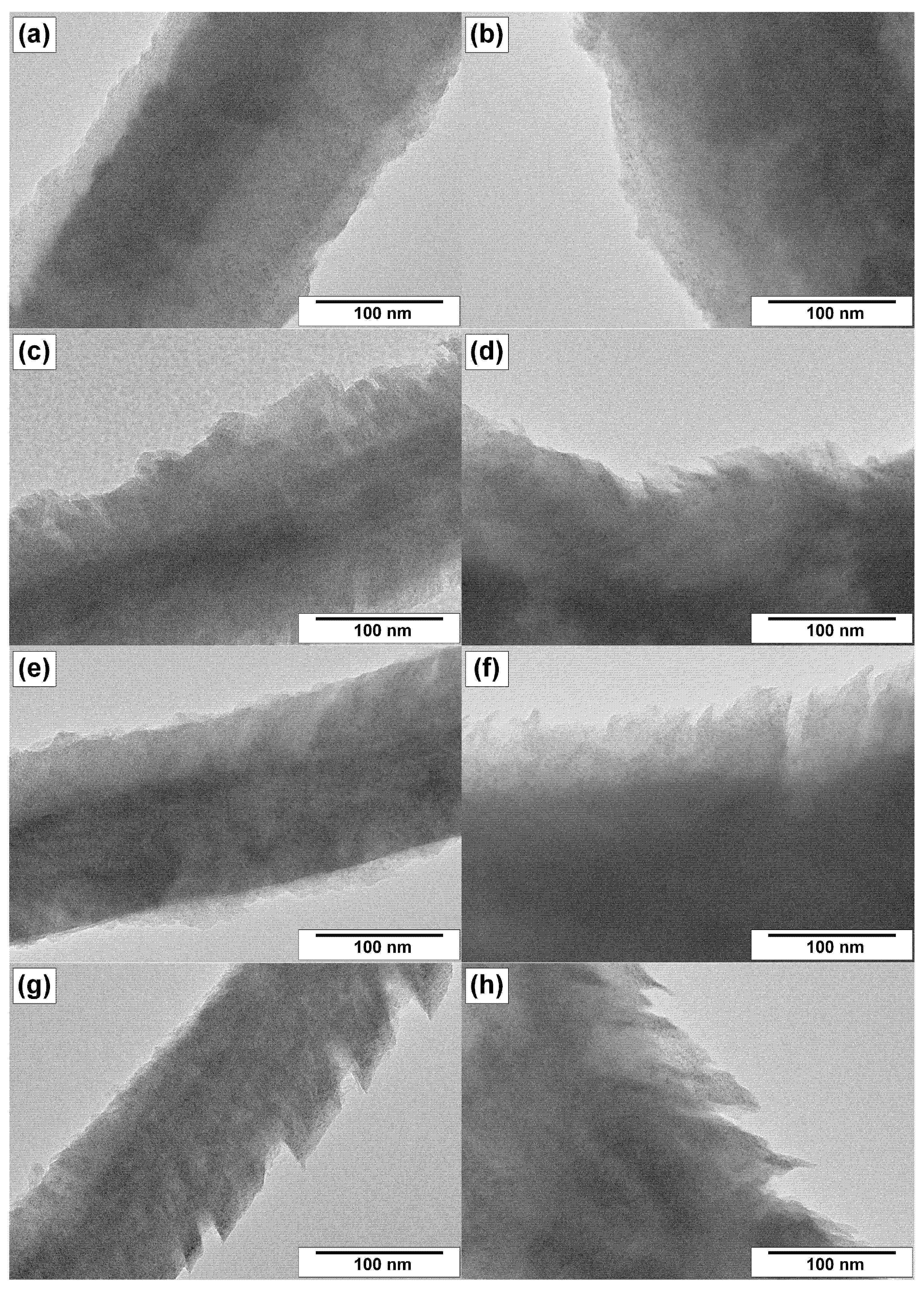
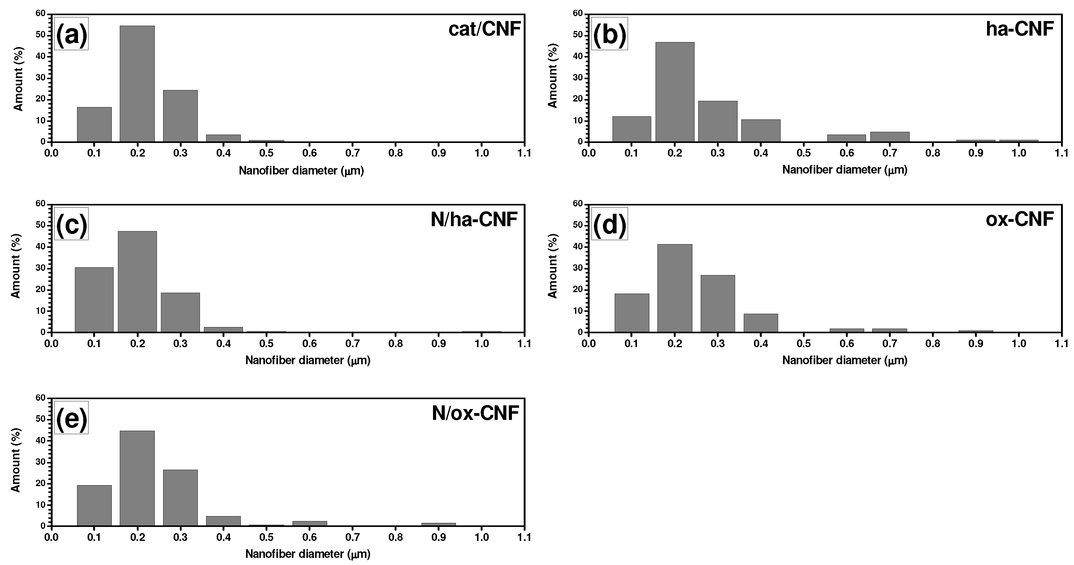
3.3. TEM Characterization of CNFs

Transmission electron microscopy gives more detailed information regarding the morphological and structural features of CNFs. Therefore, the samples were examined by this method as well. The resulting TEM images are collected in Figure 7, Figure 8 and Figure 9.
Figure 7 shows the TEM images for the as-prepared cat/CNF sample obtained via CCVD of ethylene over Ni–Cu alloy. As already mentioned, the growth of carbon filaments occurs as a result of the catalytic action of the dispersed active particles that appear due to the rapid disintegration of the initial Ni–Cu alloy. Such submicron particles of 100–200 nm in size can be clearly seen in Figure 7. One type of particle has a relatively symmetric shape and carries on the growth of carbon filaments in two opposite directions (Figure 7a). At the same time, these particles possess a relief surface without expressed faceting. The second type of particle is alloyed crystallites connected by three or more carbon filaments (Figure 7b). Such particles are clearly faceted. The crystallite plates, where the CNF growth takes place, are perpendicular to the axes of carbon filaments, thus indicating the formation of the stacked structure of CNFs.
It is important to note that in all case, the particles are not entirely covered with carbon. There are places on the surface that are free of carbon, which are responsible for the catalytic decomposition of ethylene molecules and the supply of carbon atoms [66]. These particles are easily accessible for any reagents and, therefore, they can be completely removed from the composition of CNFs even under mild treatment conditions. On the other hand, the acidic pretreatment breaks the integrity of CNFs. As expected, these procedures lead to the breakage of the filaments at the places of removed metal particles and their crushing into two and more pieces. At the same time, the filaments themselves are not fragile. They can stand even boiling in acids without further lengthwise destruction.
Figure 8 and Figure 9 present the TEM images of the same magnification for the samples cat/CNF, ox-CNF, N/ha-CNF, and N/ox-CNF, which allows their structural features to be compared. It is evident that the structure of filaments was not significantly changed during the acidic pretreatment and the subsequent N-functionalization. All the fibers are characterized by a dense packing in the bulk and a loose rough surface.
In some cases, the surface of filaments is covered with a thin layer of carbon with a different character of the graphite packing (Figure 8a,c and Figure 9a,e). The boundary interface is obviously seen in these images. The loose surface of CNFs seems to be more liable for the structural changes under the action of oxidative treatment or N-functionalization. Thus, the carbon fibers with a fringe on the surface were found in the case of CNFs post-functionalized with melamine (Figure 9f,h). At the same time, despite the surface loosening, the structure of the core part of carbon filaments within the composition of N/ha-CNF and N/ox-CNF did not suffer any visual changes.
Based on numerous SEM and TEM data acquired for all studied samples, it was possible to statistically measure the diameter distributions for the carbon nanofibers. The obtained results are presented as diagrams in Figure 10. It is obvious from the comparison of given data that the acidic treatment (both methods) and subsequent N-functionalization had an insignificant effect on the CNF diameter distribution. The measured average diameter of CNFs for all the samples was around 200 nm, regardless to the treatment conditions. The obtained result confirms that the proposed method for N-functionalization of carbon nanofibers appears to be non-destructive.
Therefore, it can be concluded that the proposed approach for the pretreatment of CNFs before their N-functionalization allows the metal particles of the catalysts to be effectively eliminated from the fiber’s structure. The structure and the integrity of the initial filaments as well as their diameter distribution remained almost the same. The post-modification of these CNFs with melamine also did not affect these characteristics noticeably; however, the surface structure was being changed and the surface layer of the filaments became significantly looser.

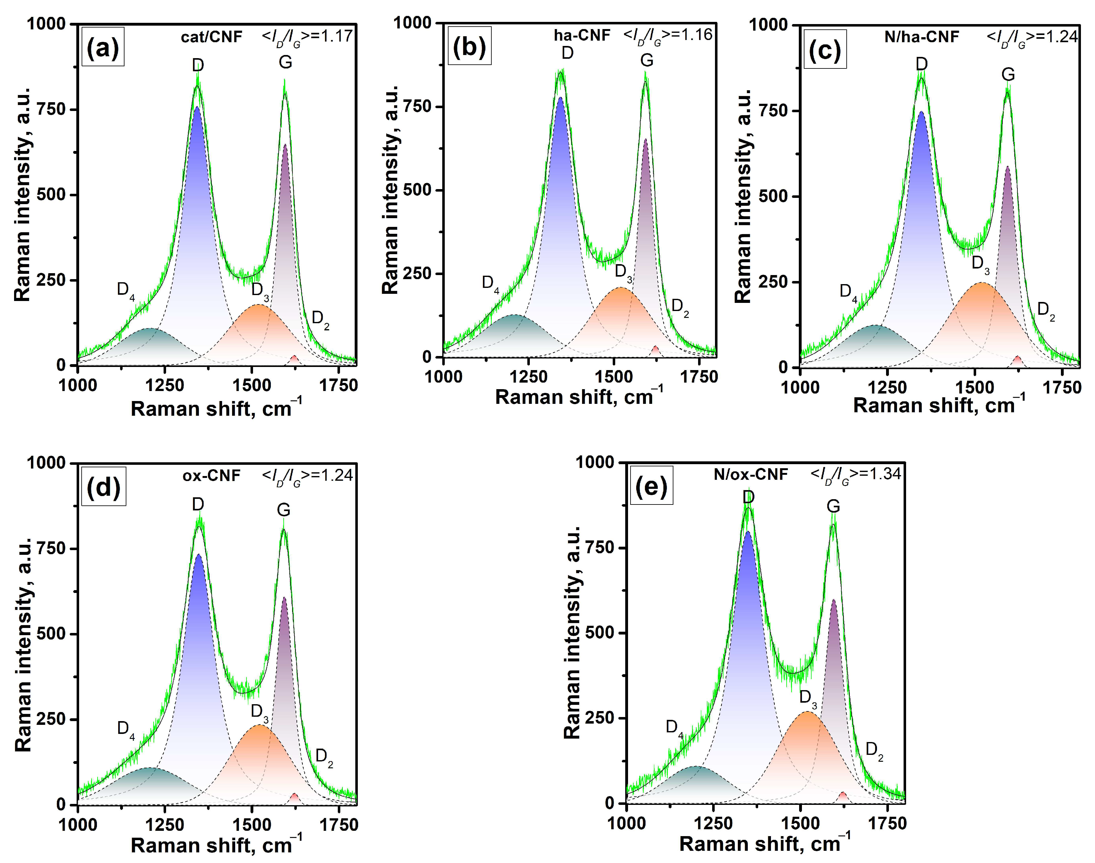
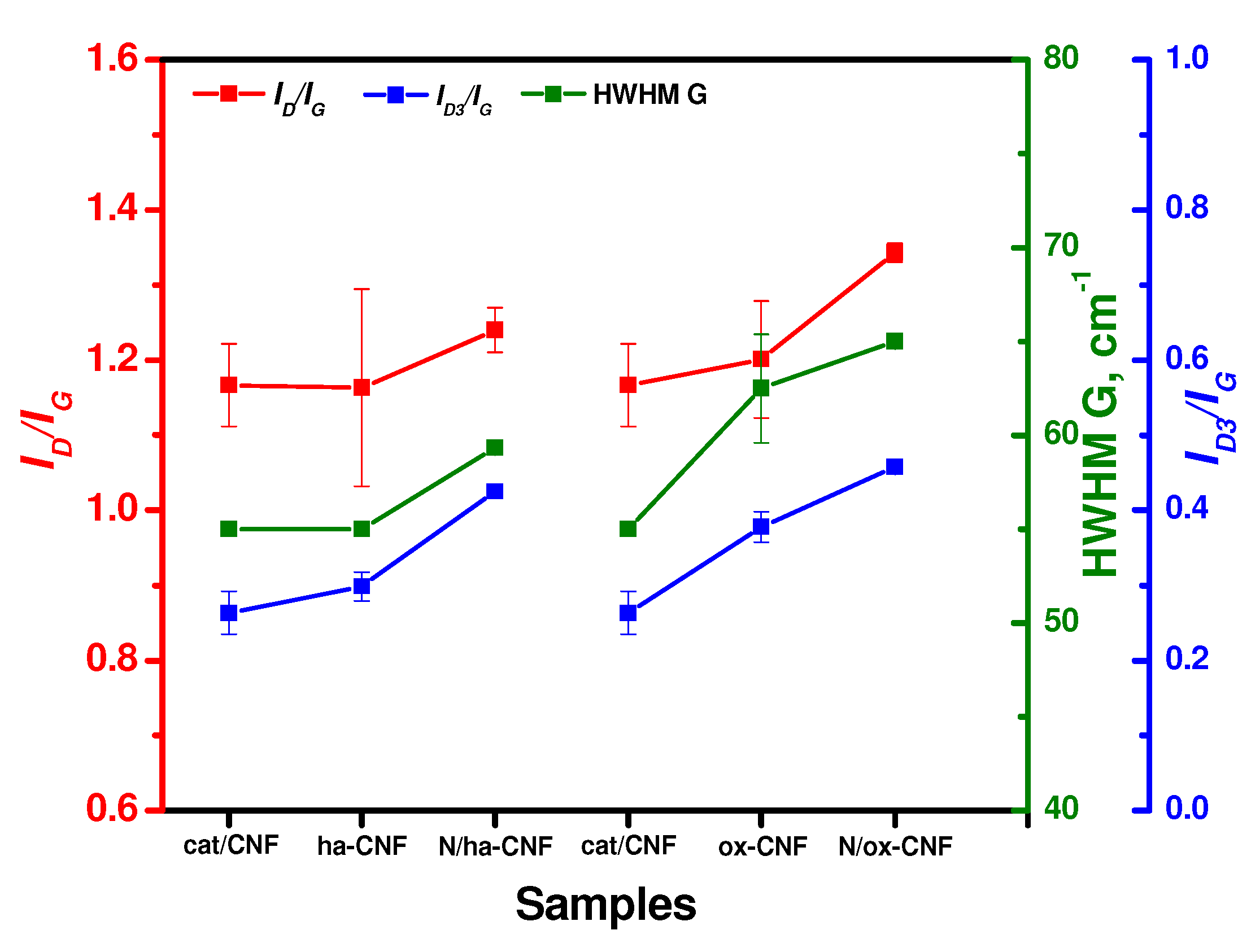
3.4. Raman Spectroscopy Data

Another informative method to study the structure and orderliness of CNFs is Raman spectroscopy. The typical Raman spectra of the samples in a region of the first order bands are shown in Figure 11. The spectra are characterized by the G bands at ~1595 cm−1 corresponding to the allowed vibrations E2g of the hexagonal graphite lattice [67,68] and by the disorder-induced D band (activated A1g mode due to the finite crystal size) at 1345 cm−1, which is a characteristic of disordered carbon materials [68,69]. Using a phenomenological three-stage model for the ordering trajectory from tetrahedral amorphous carbon to graphite or the amorphization trajectory considering the change in the G band position for the wavelength of 514.5 nm from 1581 to 1600, 1510, and 1560 cm−1, respectively, the studied samples can be assigned closer to nanocrystalline graphite [68].
For all the samples, D2 bands can be observed at ~1618 cm−1, D3 at ~1520 cm−1, and D4 at ~1208 cm−1. The D2 bands correspond to a disordered graphitic lattice (surface graphene layers, E2g-symmetry) [70], while the two other bands can be assigned to amorphous carbon and disordered graphitic lattice (A1g-symmetry) or polyenes [71], which is typical for soot and related carbonaceous materials.
The second order bands are ill-defined and very close to each other in intensity for all the studied samples. The characteristic intensities of the 2D bands at ~2700 cm−1 and D + D2 at 2934 cm−1 were I2D/IG ~ 0.11 and ID + D2/IG ~ 0.14, respectively. Taking into account the half-width values (HWHM) of the G band > 45 cm−1 and according to Ferrari and Robertson [68], the cluster diameter (or in-plane correlation length) La can be approximated from the ID/IG ratio using the equation ID/IG = C′(λ)·La2, where C′ is of ~0.0055 for the wavelength of 514.5 nm. The obtained La values lie in a range of 13.3–15.7 Å.
The changes of the main parameters (ID/IG, HWHM G, and ID3/IG) resulting from the pretreatment and post-functionalization of CNFs are shown in Figure 12. Note that each value is an average for four points. As seen, the pretreatment of the initial cat/CNF sample in hydrochloric acid led to an insignificant increase in the portion of amorphous carbon (ID3/IG). The oxidative treatment in a mixture of sulfuric and nitric acids (ox-CNF sample), in addition to an increase in the ID3/IG ratio, also increased the HWHM G value and the ID/IG ratio. This indicates a higher number of defects along with an increased portion of crystalline carbon. In other words, this acidic treatment procedure decreased the portion of disordered carbon on the surface of CNFs. In should be noted that a similar effect of etching-out the disordered carbon from the surface of carbon paper using a solution of sulfuric acid being accompanied by an increase in the ID/IG ratio has been reported in the literature [72]. However, the authors interpreted this change in the ID/IG ratio oppositely—as an increase in the disorder degree of carbon, which is the only explanation if no analysis of the HWHM G parameter and no approximation of the La value are considered.
The post-functionalization of CNFs with melamine resulted in a synchronous increase in the ID/IG ratio, the HWHM G parameter, and the portion of amorphous carbon ID3/IG (Figure 12). This observation can be interpreted as a rise of the disordered carbon portion on the surface of CNFs. Therefore, it can be concluded that all the modification procedures dealt only with the amorphous carbon and the surface layer of CNFs.

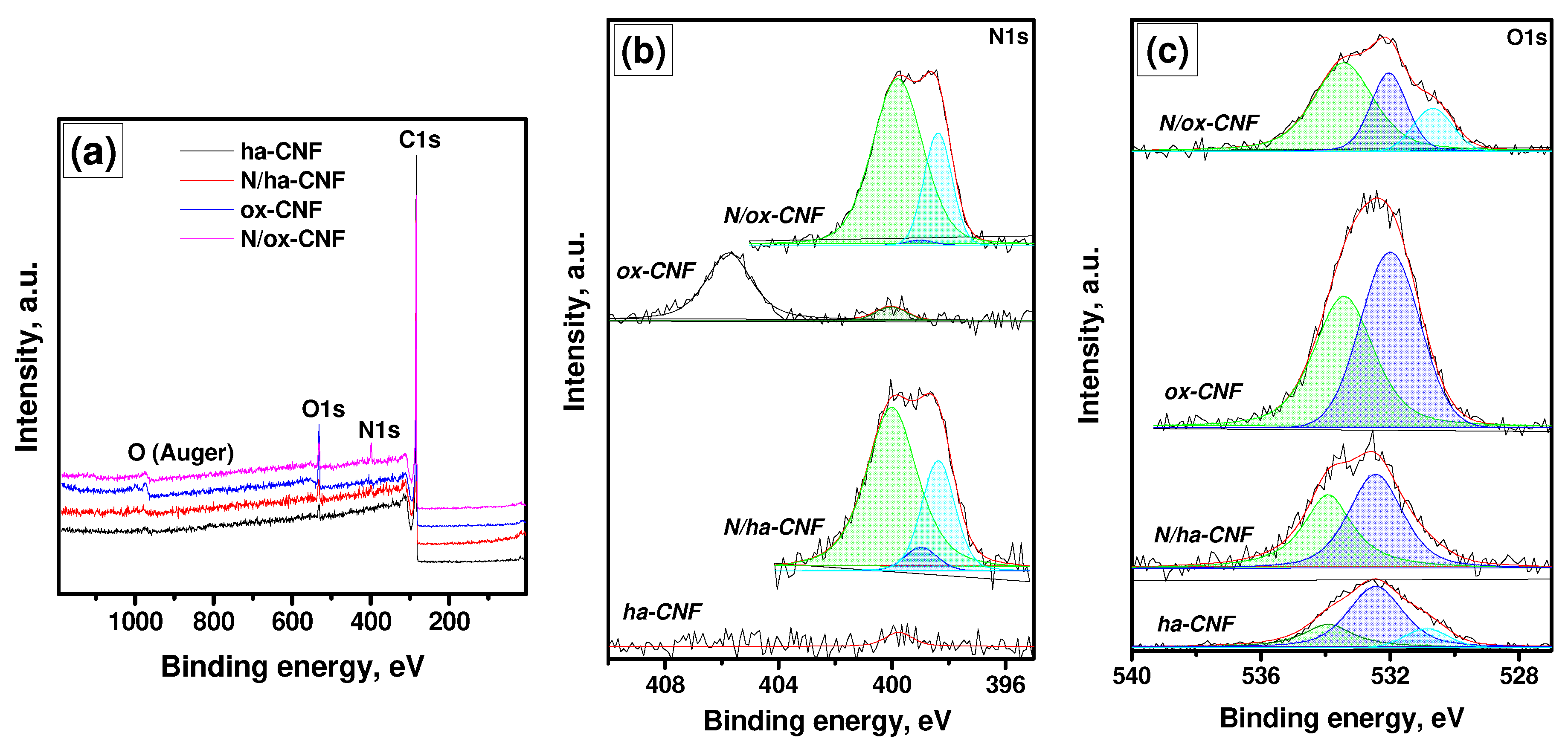
3.5. XPS Study of CNFs

The qualitative and quantitative estimations of the number of introduced nitrogen and oxygen atoms can be made by means of XPS analysis. According to the survey spectra presented in Figure 13a, the studied CNF samples contain atoms of carbon, oxygen, and nitrogen only. The atomic ratios O/C and N/C are summarized in Table 4.
Figure 13b,c shows the spectra of the N 1s and O 1s regions recorded using the monochromatic radiation AlKα. The binding energy (BE) values, the corresponding species, and their ratios to carbon for all the registered components in these spectra are compared in Table 5 and Table 6. In cases of the ha-CNF and ox-CNF samples, the spectra contain low-intensive peaks at ~ 400 eV, whose appearance could have been caused by the presence of a trace amount of nitrogen. Such a low intensity of these peaks does not allow identifying the state of these species. In addition, in the spectrum of ox-CNF, a state with BE of ~405.8 eV is predominant. This state can be definitely identified as C-NO2 groups [73,74]. For both the samples treated with melamine, three states of nitrogen are observed with BE at 398.4, 399.0, and 399.8–400.0 eV. The first (398.4 eV) and second (399.0 eV) states correspond to C-NH2 groups [75,76] and C=N-C fragments [75,77], respectively. Note that the state with BE of 398.4 eV can be also attributed to C≡N species [61,75]. The state with BE of ~400 eV is usually assigned to pyrrolic nitrogen [76,77,78]. However, the peak of pyrrolic N is overlapped in XPS spectra by nitrogen of diazine and triazine rings [76].
The presence of an intensive peak at BE near 399 eV in the spectrum of the N/ox-CNF sample allows for the assumption that there was a large amount of residual melamine (or its fragments) in this sample. Note that in the melamine spectrum, nitrogen is in two states with BE of 398.6 eV (C-NH2) and 399.2 eV (C=N-C) [75].
The O 1s spectra for the samples ha-CNF, N/ha-CNF, and N/ox-CNF contain components that can be attributed to the following groups (Figure 13c, Table 6): C(O)O with BE of 530.7–530.8 eV; C=O with BE of 532.0–532.4 eV; and C-OH with BE of 533.4–534.0 eV [79,80]. In the case of the ox-CNF sample, the components in the XPS spectrum correspond to C=O and C-OH groups, and the latter ones are overlapped with –NO2 groups [79,80,81].
Therefore, the performed XPS study confirmed the introduction of heteroatoms (O and N) into the structure of carbon nanofibers during the pretreatment and post-functionalization procedures. Both of the pretreatment regimes caused the complete elimination of metal particles of the catalyst from the composition of CNFs. No components assigned to nickel or copper were observed in XPS spectra. The drastic oxidative treatment (ox-CNF sample) resulted in the modification of the surface of the CNFs with ~11.8 at% of oxygen. Under the mild conditions (ha-CNF sample), the oxidation of the CNF’s surface also took place, but to a lower degree (~2.5 at% of oxygen). The N-functionalization of these samples with melamine allowed for the introduction of ~1.4 and ~4.3 at% of nitrogen for the N/ha-CNF and N/ox-CNF samples, respectively. It is important to note that the oxygen content decreased to 6.5 at% for N/ox-CNF and increased to 4.6 at% for N/ha-CNF. Such an opposite behavior is supposedly connected with the formation of C-NO2 groups in the latter case.
By comparing the results of the present research with the literature data related to the synthesis and characterization of the N-doped CNFs, it can be seen that the produced N-CNFs contained a nitrogen amount of several percent which is rather typical for N-CNM materials [4,7,9,12,16,20,29,36]. This is probably related to the comparatively low porosity and flexible structure of CNFs as well as to the application of a post-functionalization method, which mainly affects the surface of carbon fibers. The higher amount of nitrogen can be introduced into the structure of more porous and/or ordered carbons [6,11,14], microspheres [10], and tubes [15], including the use of severe conditions for the functionalization [25].

4. Conclusions

In present work, the carbon nanofibers obtained via CCVD of ethylene at 550 °C over an Ni–Cu alloy were modified via the introduction of O and N heteroatoms. The application of a low-temperature nitrogen-adsorption method, SEM and TEM, Raman spectroscopy, and XPS technique gave an opportunity to perform an in-depth study of the modification process. The first stage of this process was the pretreatment with hydrochloric acid (mild conditions) or with a mixture of sulfuric and nitric acids under heating (drastic conditions). Both these procedures allowed the complete elimination of metal particles of the catalysts from the structure of carbon filaments. The elimination of metal particles, in its turn, resulted in a breakage of filaments in places where the particles were located. Thus, the filaments became shorter, and the slight compaction of the carbon material occurred. Therefore, the specific surface area of the samples after the acidic pretreatment diminished insignificantly. According to TEM and Raman spectroscopy data, the modification process dealt mostly with the surface changes. The appearance of oxygen species on the surface of CNFs was registered in both the pretreatment cases. The drastic oxidative conditions gave an oxygen content as high as 11.8 at%. The subsequent post-functionalization with melamine did not practically affect the morphology of the CNF samples. At the same time, it allowed for the introduction of 1.4 and 4.3 at% of nitrogen into the structure of ha-CNF and ox-CNF samples, respectively. Therefore, the proposed approach proved to be applicable for the modification of carbon nanofibers with heteroatoms (O and N), which are primarily demanded as a support for heterogeneous catalysts used in hydrodechlorination, selective hydrogenation, and other processes.

Author Contributions

Conceptualization, I.V.M. and A.A.V.; methodology, I.V.M., M.S.M., A.V.N. and V.O.S.; investigation, T.A.M., Y.I.B., A.B.A. and A.M.D.; writing—original draft preparation, T.A.M., I.V.M., A.B.A., A.V.N. and V.O.S.; writing—review and editing, I.V.M., M.S.M. and A.A.V.; funding acquisition, I.V.M. All authors have read and agreed to the published version of the manuscript.

Funding

This work was supported by the Ministry of Science and Higher Education of the Russian Federation (project No. AAAA-A21-121011390054-1).

Institutional Review Board Statement

Not applicable.

Informed Consent Statement

Not applicable.

Data Availability Statement

Data are contained within the article.

Acknowledgments

Characterization of the samples was performed using the equipment of the Center of Collective Use “National Center of Catalysts Research”. TEM studies were performed in the Krasnoyarsk Regional Center of Research Equipment of the Federal Research Center “Krasnoyarsk Science Center SB RAS”. The authors are grateful to A. N. Serkova for her help in SEM studies, to M. N. Volochaev for his help in TEM studies, and to A. S. Kadtsyna for preparing the CNF samples.

Conflicts of Interest

The authors declare no conflict of interest. The funders had no role in the design of the study; in the collection, analyses, or interpretation of data; in the writing of the manuscript; or in the decision to publish the results.

References

  1. Lee, W.J.; Maiti, U.N.; Lee, J.M.; Lim, J.; Han, T.H.; Kim, S.O. Nitrogen-doped carbon nanotubes and graphene composite structures for energy and catalytic applications. Chem. Commun. 2014, 50, 6818–6830. [Google Scholar] [CrossRef] [PubMed]
  2. Podyacheva, O.Y.; Ismagilov, Z.R. Nitrogen-doped carbon nanomaterials: To the mechanism of growth, electrical conductivity and application in catalysis. Catal. Today 2015, 249, 12–22. [Google Scholar] [CrossRef]
  3. Inagaki, M.; Toyoda, M.; Soneda, Y.; Morishita, T. Nitrogen-doped carbon materials. Carbon 2018, 132, 104–140. [Google Scholar] [CrossRef]
  4. Hulicova-Jurcakova, D.; Seredych, M.; Lu, G.Q.; Bandosz, T.J. Combined effect of nitrogen- and oxygen-containing functional groups of microporous activated carbon on its electrochemical performance in supercapacitors. Adv. Func. Mater. 2009, 19, 438–447. [Google Scholar] [CrossRef]
  5. Nasini, U.B.; Bairi, V.G.; Ramasahayam, S.K.; Bourdo, S.E.; Viswanathan, T.; Shaikh, A.U. Phosphorous and nitrogen dual heteroatom doped mesoporous carbon synthesized via microwave method for supercapacitor application. J. Power Sources 2014, 250, 257–265. [Google Scholar] [CrossRef]
  6. Gao, F.; Shao, G.; Qu, J.; Lv, S.; Li, Y.; Wu, M. Tailoring of porous and nitrogen-rich carbons derived from hydrochar for high-performance supercapacitor electrodes. Electrochim. Acta 2015, 155, 201–208. [Google Scholar] [CrossRef]
  7. Liu, C.; Wang, J.; Li, J.; Zeng, M.; Luo, R.; Shen, J.; Sun, X.; Han, W.; Wang, L. Synthesis of N-doped hollow-structured mesoporous carbon nanospheres for high-performance supercapacitors. ACS Appl. Mater. Interf. 2016, 8, 7194–7204. [Google Scholar] [CrossRef]
  8. Yang, Y.; Yang, F.; Lee, S.; Li, X.; Zhao, H.; Wang, Y.; Hao, S.; Zhang, X. Facile fabrication of MnOx and N co-doped hierarchically porous carbon microspheres for high-performance supercapacitors. Electrochim. Acta 2016, 191, 1018–1025. [Google Scholar] [CrossRef] [Green Version]
  9. Kim, J.; Lim, H.; Jyoung, J.-Y.; Lee, E.-S.; Yi, J.S.; Lee, D. Effects of doping methods and kinetic relevance of N and O atomic co-functionalization on carbon electrode for V(IV)/V(V) redox reactions in vanadium redox flow battery. Electrochim. Acta 2017, 245, 724–733. [Google Scholar] [CrossRef]
  10. Ma, C.; Chen, X.; Long, D.; Wang, J.; Qiao, W.; Ling, L. High-surface-area and high-nitrogen-content carbon microspheres prepared by a pre-oxidation and mild KOH activation for superior supercapacitor. Carbon 2017, 118, 699–708. [Google Scholar] [CrossRef]
  11. Chen, Y.; Xiao, Z.; Liu, Y.; Fan, L.-Z. A simple strategy toward hierarchically porous graphene/nitrogen-rich carbon foams for high-performance supercapacitors. J. Mater. Chem. A 2017, 5, 24178–24184. [Google Scholar] [CrossRef]
  12. Sutarsis; Patra, J.; Su, C.-Y.; Li, J.; Bresser, D.; Passerini, S.; Chang, J.-K. Manipulation of nitrogen-heteroatom configuration for enhanced charge-storage performance and reliability of nanoporous carbon electrodes. ACS Appl. Mater. Interf. 2020, 12, 32797–32805. [Google Scholar] [CrossRef] [PubMed]
  13. Luo, Y.; Lu, Y.; Wang, Q.; Xu, F.; Sun, L.; Wang, Y.; Lao, J.; Liao, L.; Zhang, K.; Zhang, H.; et al. Porous carbon with facial tuning of the heteroatom N by polyvinylidene chloride dehalogenation toward enhanced supercapacitor performance. J. Electrochem. Energy Conv. Stor. 2023, 20, 011004. [Google Scholar] [CrossRef]
  14. Li, Z.; Liu, J.; Xia, C.; Li, F. Nitrogen-functionalized ordered mesoporous carbons as multifunctional supports of ultrasmall Pd nanoparticles for hydrogenation of phenol. ACS Catal. 2013, 3, 2440–2448. [Google Scholar] [CrossRef]
  15. Chen, S.; Qi, P.; Chen, J.; Yuan, Y. Platinum nanoparticles supported on N-doped carbon nanotubes for the selective oxidation of glycerol to glyceric acid in a base-free aqueous solution. RSC Adv. 2015, 5, 31566–31574. [Google Scholar] [CrossRef] [Green Version]
  16. Soares, O.S.G.P.; Rocha, R.P.; Gonçalves, A.G.; Figueiredo, J.L.; Órfão, J.J.M.; Pereira, M.F.R. Highly active N-doped carbon nanotubes prepared by an easy ball milling method for advanced oxidation processes. Appl. Catal. B Environ. 2016, 192, 296–303. [Google Scholar] [CrossRef]
  17. Ferrero, G.A.; Fuertes, A.B.; Sevilla, M.; Titirici, M.-M. Efficient metal-free N-doped mesoporous carbon catalysts for ORR by a template-free approach. Carbon 2016, 106, 179–187. [Google Scholar] [CrossRef] [Green Version]
  18. Liang, P.; Zhang, C.; Duan, X.; Sun, H.; Liu, S.; Tade, M.O.; Wang, S. N-doped graphene from metal–organic frameworks for catalytic oxidation of p-hydroxylbenzoic acid: N-functionality and mechanism. ACS Sustain. Chem. Eng. 2017, 5, 2693–2701. [Google Scholar] [CrossRef]
  19. Mian, M.M.; Liu, G.; Zhou, H. Preparation of N-doped biochar from sewage sludge and melamine for peroxymonosulfate activation: N-functionality and catalytic mechanisms. Sci. Total Environ. 2020, 744, 140862. [Google Scholar] [CrossRef]
  20. Anfar, Z.; El Fakir, A.A.; Zbair, M.; Hafidi, Z.; Amedlous, A.; Majdoub, M.; Farsad, S.; Amjlef, A.; Jada, A.; El Alem, N. New functionalization approach synthesis of Sulfur doped, Nitrogen doped and Co-doped porous carbon: Superior metal-free Carbocatalyst for the catalytic oxidation of aqueous organics pollutants. Chem. Eng. J. 2021, 405, 126660. [Google Scholar] [CrossRef]
  21. Lee, B.; Tian, S.; Xiong, G.; Yang, Y.; Zhu, X. Solvothermal synthesis of transition metal (iron/copper) and nitrogen co−doped carbon nanomaterials: Comparing their peroxidase—Like properties. J. Nanopart. Res. 2022, 24, 85. [Google Scholar] [CrossRef]
  22. Prabakaran, E.; Pillay, K. Synthesis and characterization of fluorescent N-CDs/ZnONPs nanocomposite for latent fingerprint detection by using powder brushing method. Arabian J. Chem. 2020, 13, 3817–3835. [Google Scholar] [CrossRef]
  23. Pérez-Cadenas, M.; Moreno-Castilla, C.; Carrasco-Marín, F.; Pérez-Cadenas, A.F. Surface chemistry, porous texture, and morphology of N-doped carbon xerogels. Langmuir 2009, 25, 466–470. [Google Scholar] [CrossRef] [PubMed]
  24. Maboya, W.K.; Coville, N.J.; Mhlanga, S.D. Fabrication of chlorine nitrogen co-doped carbon nanomaterials by an injection catalytic vapor deposition method. Mater. Res. Express 2021, 8, 015007. [Google Scholar] [CrossRef]
  25. Kenzhin, R.M.; Bauman, Y.I.; Volodin, A.M.; Mishakov, I.V.; Vedyagin, A.A. One-step synthesis of nitrogen-doped carbon nanofibers from melamine over nickel alloy in a closed system. Chem. Phys. Lett. 2017, 685, 259–262. [Google Scholar] [CrossRef]
  26. Kenzhin, R.M.; Bauman, Y.I.; Volodin, A.M.; Mishakov, I.V.; Vedyagin, A.A. Interaction of heteroatom-containing organic compounds with bulk nickel alloy in a closed reactor system. Juniper Online J. Mater. Sci. 2018, 4, 555633. [Google Scholar] [CrossRef]
  27. Potylitsyna, A.R.; Mishakov, I.V.; Bauman, Y.I.; Kibis, L.S.; Shubin, Y.V.; Volochaev, M.N.; Melgunov, M.S.; Vedyagin, A.A. Metal dusting as a key route to produce functionalized carbon nanofibers. Reac. Kinet. Mech. Catal. 2022, 135, 1387–1404. [Google Scholar] [CrossRef]
  28. Brzhezinskaya, M.; Mishakov, I.V.; Bauman, Y.I.; Shubin, Y.V.; Maksimova, T.A.; Stoyanovskii, V.O.; Gerasimov, E.Y.; Vedyagin, A.A. One-pot functionalization of catalytically derived carbon nanostructures with heteroatoms for toxic-free environment. Appl. Surf. Sci. 2022, 590, 153055. [Google Scholar] [CrossRef]
  29. Jiang, Y.; Zhang, J.; Qin, Y.-H.; Niu, D.-F.; Zhang, X.-S.; Niu, L.; Zhou, X.-G.; Lu, T.-H.; Yuan, W.-K. Ultrasonic synthesis of nitrogen-doped carbon nanofibers as platinum catalyst support for oxygen reduction. J. Power Sources 2011, 196, 9356–9360. [Google Scholar] [CrossRef]
  30. Yin, J.; Qiu, Y.; Yu, J.; Zhou, X.; Wu, W. Enhancement of electrocatalytic activity for oxygen reduction reaction in alkaline and acid media from electrospun nitrogen-doped carbon nanofibers by surface modification. RSC Adv. 2013, 3, 15655–15663. [Google Scholar] [CrossRef]
  31. Sevilla, M.; Yu, L.; Zhao, L.; Ania, C.O.; Titiricic, M.-M. Surface modification of CNTs with N-doped carbon: An effective way of enhancing their performance in supercapacitors. ACS Sustain. Chem. Eng. 2014, 2, 1049–1055. [Google Scholar] [CrossRef] [Green Version]
  32. Zhang, J.; Zhang, X.; Zhou, Y.; Guo, S.; Wang, K.; Liang, Z.; Xu, Q. Nitrogen-doped hierarchical porous carbon nanowhisker ensembles on carbon nanofiber for high-performance supercapacitors. ACS Sustain. Chem. Eng. 2014, 2, 1525–1533. [Google Scholar] [CrossRef]
  33. Kerdi, F.; Ait Rass, H.; Pinel, C.; Besson, M.; Peru, G.; Leger, B.; Rio, S.; Monflier, E.; Ponchel, A. Evaluation of surface properties and pore structure of carbon on the activity of supported Ru catalysts in the aqueous-phase aerobic oxidation of HMF to FDCA. Appl. Catal. A Gen. 2015, 506, 206–219. [Google Scholar] [CrossRef]
  34. Wang, T.; Chen, Z.-X.; Chen, Y.-G.; Yang, L.-J.; Yang, X.-D.; Ye, J.-Y.; Xia, H.-P.; Zhou, Z.-Y.; Sun, S.-G. Identifying the active site of N-doped graphene for oxygen reduction by selective chemical modification. ACS Energy Lett. 2018, 3, 986–991. [Google Scholar] [CrossRef]
  35. Butsyk, O.; Olejnik, P.; Romero, E.; Plonska-Brzezinska, M.E. Postsynthetic treatment of carbon nano-onions: Surface modification by heteroatoms to enhance their capacitive and electrocatalytic properties. Carbon 2019, 147, 90–104. [Google Scholar] [CrossRef]
  36. Ruiz-Garcia, C.; Heras, F.; Calvo, L.; Alonso-Morales, N.; Rodriguez, J.J.; Gilarranz, M.A. Improving the activity in hydrodechlorination of Pd/C catalysts by nitrogen doping of activated carbon supports. J. Environ. Chem. Eng. 2020, 8, 103689. [Google Scholar] [CrossRef]
  37. Golub, F.S.; Beloshapkin, S.; Gusel’nikov, A.V.; Bolotov, V.A.; Parmon, V.N.; Bulushev, D.A. Boosting hydrogen production from formic acid over Pd catalysts by deposition of N-containing precursors on the carbon support. Energies 2019, 12, 3885. [Google Scholar] [CrossRef] [Green Version]
  38. Li, S.; Bian, F.; Wu, X.; Sun, L.; Yang, H.; Meng, X.; Qin, G. Microstructure evolution and its correlation with performance in nitrogen-containing porous carbon prepared by polypyrrole carbonization: Insights from hybrid calculations. Materials 2022, 15, 3705. [Google Scholar] [CrossRef]
  39. Mishakov, I.V.; Vedyagin, A.A.; Bauman, Y.I.; Shubin, Y.V.; Buyanov, R.A. Synthesis of carbon nanofibers via catalytic chemical vapor deposition of halogenated hydrocarbons. In Carbon Nanofibers: Synthesis, Applications and Performance; Chang-Seop, L., Ed.; Nova Science Publishers: Hauppauge, NY, USA, 2018; pp. 77–181. [Google Scholar]
  40. Mishakov, I.V.; Afonnikova, S.D.; Bauman, Y.I.; Shubin, Y.V.; Trenikhin, M.V.; Serkova, A.N.; Vedyagin, A.A. Carbon erosion of a bulk nickel–copper alloy as an effective tool to synthesize carbon nanofibers from hydrocarbons. Kinet. Catal. 2022, 63, 97–107. [Google Scholar] [CrossRef]
  41. Atwater, M.A.; Guevara, L.N.; Knauss, S.J. Multifunctional porous catalyst produced by mechanical alloying. Mater. Res. Lett. 2019, 7, 131–136. [Google Scholar] [CrossRef]
  42. Mishakov, I.V.; Bauman, Y.I.; Korneev, D.V.; Vedyagin, A.A. Metal dusting as a route to produce active catalyst for processing chlorinated hydrocarbons into carbon nanomaterials. Top. Catal. 2013, 56, 1026–1032. [Google Scholar] [CrossRef]
  43. Zhu, Q.-L.; Xu, Q. Immobilization of ultrafine metal nanoparticles to high-surface-area materials and their catalytic applications. Chem 2016, 1, 220–245. [Google Scholar] [CrossRef]
  44. Saadun, A.J.; Ruiz–Ferrando, A.; Büchele, S.; Faust Akl, D.; López, N.; Pérez–Ramírez, J. Structure sensitivity of nitrogen–doped carbon–supported metal catalysts in dihalomethane hydrodehalogenation. J. Catal. 2021, 404, 291–305. [Google Scholar] [CrossRef]
  45. Liu, S.; Otero, J.A.; Martin-Martinez, M.; Rodriguez-Franco, D.; Rodriguez, J.J.; Gómez-Sainero, L.M. Understanding hydrodechlorination of chloromethanes. Past and future of the technology. Catalysts 2020, 10, 1462. [Google Scholar] [CrossRef]
  46. Chesnokov, V.V.; Kriventsov, V.V.; Malykhin, S.E.; Svintsitskiy, D.A.; Podyacheva, O.Y.; Lisitsyn, A.S.; Richards, R.M. Nature of active palladium sites on nitrogen doped carbon nanofibers in selective hydrogenation of acetylene. Diam. Relat. Mater. 2018, 89, 67–73. [Google Scholar] [CrossRef]
  47. Hu, F.; Leng, L.; Zhang, M.; Chen, W.; Yu, Y.; Wang, J.; Horton, J.H.; Li, Z. Direct synthesis of atomically dispersed palladium atoms supported on graphitic carbon nitride for efficient selective hydrogenation reactions. ACS Appl. Mater. Interf. 2020, 12, 54146–54154. [Google Scholar] [CrossRef]
  48. Glyzdova, D.V.; Vedyagin, A.A.; Tsapina, A.M.; Kaichev, V.V.; Trigub, A.L.; Trenikhin, M.V.; Shlyapin, D.A.; Tsyrulnikov, P.G.; Lavrenov, A.V. A study on structural features of bimetallic Pd-M/C (M: Zn, Ga, Ag) catalysts for liquid-phase selective hydrogenation of acetylene. Appl. Catal. A-Gen. 2018, 563, 18–27. [Google Scholar] [CrossRef]
  49. Bulushev, D.A.; Bulusheva, L.G. Catalysts with single metal atoms for the hydrogen production from formic acid. Catal. Rev. 2022, 64, 835–874. [Google Scholar] [CrossRef]
  50. Suboch, A.N.; Podyacheva, O.Y. Pd Catalysts supported on bamboo-like nitrogen-doped carbon nanotubes for hydrogen production. Energies 2021, 14, 1501. [Google Scholar] [CrossRef]
  51. Kwak, Y.; Kirk, J.; Moon, S.; Ohm, T.; Lee, Y.-J.; Jang, M.; Park, L.-H.; Ahn, C.-i.; Jeong, H.; Sohn, H.; et al. Hydrogen production from homocyclic liquid organic hydrogen carriers (LOHCs): Benchmarking studies and energy-economic analyses. Energ. Conv. Manag. 2021, 239, 114124. [Google Scholar] [CrossRef]
  52. Abdin, Z.; Tang, C.; Liu, Y.; Catchpole, K. Large-scale stationary hydrogen storage via liquid organic hydrogen carriers. iScience 2021, 24, 102966. [Google Scholar] [CrossRef] [PubMed]
  53. Niermann, M.; Drünert, S.; Kaltschmitt, M.; Bonhoff, K. Liquid organic hydrogen carriers (LOHCs)—Techno-economic analysis of LOHCs in a defined process chain. Energy Environ. Sci. 2019, 12, 290–307. [Google Scholar] [CrossRef]
  54. Gómez, S.; Rendtorff, N.M.; Aglietti, E.F.; Sakka, Y.; Suárez, G. Surface modification of multiwall carbon nanotubes by sulfonitric treatment. Appl. Surf. Sci. 2016, 379, 264–269. [Google Scholar] [CrossRef]
  55. Turan, K.; Kaur, P.; Manhas, D.; Sharma, J.; Verma, G. Novel insights into the dispersed and acid-mediated surface modification of the carbon nanofibers. Mater. Chem. Phys. 2020, 239, 121978. [Google Scholar] [CrossRef]
  56. Ud Din, I.; Shaharun, M.S.; Subbarao, D.; Naeem, A. Surface modification of carbon nanofibers by HNO3 treatment. Ceram. Int. 2016, 42, 966–970. [Google Scholar] [CrossRef]
  57. Afonnikova, S.D.; Mishakov, I.V.; Bauman, Y.I.; Trenikhin, M.V.; Shubin, Y.V.; Serkova, A.N.; Vedyagin, A.A. Preparation of Ni-Cu Catalyst for carbon nanofiber production by the mechanochemical route. Top. Catal. 2022. [Google Scholar] [CrossRef]
  58. Mel’gunov, M.S.; Ayupov, A.B. Direct method for evaluation of BET adsorbed monolayer capacity. Micropor. Mesopor. Mat. 2017, 243, 147–153. [Google Scholar] [CrossRef]
  59. Sing, K. The use of nitrogen adsorption for the characterisation of porous materials. Colloids Surf. A 2001, 187–188, 3–9. [Google Scholar] [CrossRef]
  60. Gor, G.Y.; Thommes, M.; Cychosz, K.A.; Neimark, A.V. Quenched solid density functional theory method for characterization of mesoporous carbons by nitrogen adsorption. Carbon 2012, 50, 1583–1590. [Google Scholar] [CrossRef]
  61. Moulder, J.F.; Stickle, W.F.; Sobol, W.M.; Bomben, K.D. (Eds.) Handbook of X-Ray Photoelectron Spectroscopy; Perkin-Elmer Corporation Physical Electronics Division: Eden Prairie, MN, USA, 1992; p. 261. [Google Scholar]
  62. Thommes, M.; Kaneko, K.; Neimark, A.V.; Olivier, J.P.; Rodriguez-Reinoso, F.; Rouquerol, J.; Sing, K.S.W. Physisorption of gases, with special reference to the evaluation of surface area and pore size distribution (IUPAC Technical Report). Pure Appl. Chem. 2015, 87, 1051–1069. [Google Scholar] [CrossRef]
  63. Shubin, Y.V.; Bauman, Y.I.; Plyusnin, P.E.; Mishakov, I.V.; Tarasenko, M.S.; Mel’gunov, M.S.; Stoyanovskii, V.O.; Vedyagin, A.A. Facile synthesis of triple Ni-Mo-W alloys and their catalytic properties in chemical vapor deposition of chlorinated hydrocarbons. J. Alloys Compnd. 2021, 866, 158778. [Google Scholar] [CrossRef]
  64. Mishakov, I.V.; Buyanov, R.A.; Zaikovskii, V.I.; Strel’tsov, I.A.; Vedyagin, A.A. Catalytic synthesis of nanosized feathery carbon structures via the carbide cycle mechanism. Kinet. Catal. 2008, 49, 868–872. [Google Scholar] [CrossRef]
  65. Monthioux, M.; Noé, L.; Dussault, L.; Dupin, J.C.; Latorre, N.; Ubieto, T.; Romeo, E.; Royo, C.; Monzón, A.; Guimon, C. Texturising and structurising mechanisms of carbon nanofilaments during growth. J. Mater. Chem. 2007, 17, 4611–4618. [Google Scholar] [CrossRef]
  66. Chesnokov, V.V.; Buyanov, R.A. The formation of carbon filaments upon decomposition of hydrocarbons catalysed by iron subgroup metals and their alloys. Russ. Chem. Rev. 2000, 69, 623–638. [Google Scholar] [CrossRef]
  67. Nemanich, R.J.; Solin, S.A. First- and second-order Raman scattering from finite-size crystals of graphite. Phys. Rev. B 1979, 20, 392–401. [Google Scholar] [CrossRef]
  68. Ferrari, A.C.; Robertson, J. Interpretation of Raman spectra of disordered and amorphous carbon. Phys. Rev. B 2000, 61, 14095–14107. [Google Scholar] [CrossRef] [Green Version]
  69. Tuinstra, F.; Koenig, J.L. Raman Spectrum of Graphite. J. Chem. Phys. 1970, 53, 1126–1130. [Google Scholar] [CrossRef] [Green Version]
  70. Wang, Y.; Alsmeyer, D.C.; McCreery, R.L. Raman spectroscopy of carbon materials: Structural basis of observed spectra. Chem. Mater. 1990, 2, 557–563. [Google Scholar] [CrossRef]
  71. Sadezky, A.; Muckenhuber, H.; Grothe, H.; Niessner, R.; Pöschl, U. Raman microspectroscopy of soot and related carbonaceous materials: Spectral analysis and structural information. Carbon 2005, 43, 1731–1742. [Google Scholar] [CrossRef]
  72. Liu, C.; Sun, C.; Gao, Y.; Lan, W.; Chen, S. Improving the electrochemical properties of carbon paper as cathodes for microfluidic fuel cells by the electrochemical activation in different solutions. ACS Omega 2021, 6, 19153–19161. [Google Scholar] [CrossRef]
  73. Fu, W.Y.; Wang, K.F.; Lv, X.S.; Fu, H.L.; Dong, X.G.; Chen, L.; Zhang, X.M.; Jiang, G.M. Palladium nanoparticles assembled on titanium nitride for enhanced electrochemical hydrodechlorination of 2,4-dichlorophenol in water. Chin. J. Catal. 2018, 39, 693–700. [Google Scholar] [CrossRef]
  74. Lindberg, B.J.; Hedman, J. Molecular spectroscopy by means of ESCA. Chem. Scripta 1975, 7, 155–166. [Google Scholar]
  75. Dementjev, A.P.; de Graaf, A.; van de Sanden, M.C.M.; Maslakov, K.I.; Naumkin, A.V.; Serov, A.A. X-Ray photoelectron spectroscopy reference data for identification of the C3N4 phase in carbon–nitrogen films. Diam. Relat. Mater. 2000, 9, 1904–1907. [Google Scholar] [CrossRef]
  76. Kuntumalla, M.K.; Attrash, M.; Akhvlediani, R.; Michaelson, S.; Hoffman, A. Nitrogen bonding, work function and thermal stability of nitrided graphite surface: An in situ XPS, UPS and HREELS study. Appl. Surf. Sci. 2020, 525, 146562. [Google Scholar] [CrossRef]
  77. Ayiania, M.; Smith, M.; Hensley, A.J.R.; Scudiero, L.; McEwen, J.-S.; Garcia-Perez, M. Deconvoluting the XPS spectra for nitrogen-doped chars: An analysis from first principles. Carbon 2020, 162, 528–544. [Google Scholar] [CrossRef]
  78. Xu, Y.; Mo, Y.; Tian, J.; Wang, P.; Yu, H.; Yu, J. The synergistic effect of graphitic N and pyrrolic N for the enhanced photocatalytic performance of nitrogen-doped graphene/TiO2 nanocomposites. Appl. Catal. B Environ. 2016, 181, 810–817. [Google Scholar] [CrossRef]
  79. Chen, C.-M.; Zhang, Q.; Yang, M.-G.; Huang, C.-H.; Yang, Y.-G.; Wang, M.-Z. Structural evolution during annealing of thermally reduced graphene nanosheets for application in supercapacitors. Carbon 2012, 50, 3572–3584. [Google Scholar] [CrossRef]
  80. Oh, Y.J.; Yoo, J.J.; Kim, Y.I.; Yoon, J.K.; Yoon, H.N.; Kim, J.-H.; Park, S.B. Oxygen functional groups and electrochemical capacitive behavior of incompletely reduced graphene oxides as a thin-film electrode of supercapacitor. Electrochim. Acta 2014, 116, 118–128. [Google Scholar] [CrossRef] [Green Version]
  81. Folkesson, B.; Sundberg, P. A Reinvestigation of the binding energy versus atomic charge relation for oxygen from X-ray photoelectron spectroscopy. Spectroscopy Lett. 1987, 20, 193–200. [Google Scholar] [CrossRef]
Figure 1. Isotherms of nitrogen adsorption/desorption at 77 K for the studied CNF samples: (a) as-prepared and pretreated CNFs and (b) N-functionalized CNFs. The samples were treated in a vacuum (1 Pa) at 250 °C for 20 h.
Materials 15 08239 g001
Figure 2. Pore size distribution calculated by the QSDFT method using ASWin 2.02 software.
Materials 15 08239 g002
Figure 3. SEM images of the ha-CNF sample at various magnifications: (a) 3000×, (b) 10,000×, (c) 30,000×, (d) 60,000×, and (e) 100,000×.
Materials 15 08239 g003
Figure 4. SEM images of the N/ha-CNF sample at various magnifications: (a) 3000×, (b) 10,000×, (c) 30,000×, (d) 60,000×, and (e) 100,000×.
Materials 15 08239 g004
Figure 5. SEM images of the ox-CNF sample at various magnifications: (a) 3000×, (b) 10,000×, (c) 30,000×, (d) 60,000×, and (e) 100,000×.
Materials 15 08239 g005
Figure 6. SEM images of the N/ox-CNF sample at various magnifications: (a) 3000×, (b) 10,000×, (c) 30,000×, (d) 60,000×, and (e) 100,000×.
Materials 15 08239 g006
Figure 7. TEM images of the cat/CNF sample prepared via CCVD of ethylene at 550 °C over Ni–Cu alloy: (a) two-directional growth of carbon filaments and (b) three-directional growth of carbon filaments.
Materials 15 08239 g007
Figure 8. TEM images of the studied samples: (a) cat/CNF, (b) ox-CNF, (c) N/ha-CNF, and (d) N/ox-CNF.
Materials 15 08239 g008
Figure 9. Magnified TEM images of the filament’s surface for the studied samples: (a,b) cat/CNF, (c,d) ox-CNF (e,f) N/ha-CNF, and (g,h) N/ox-CNF.
Materials 15 08239 g009
Figure 10. CNF diameter distributions depending on the treatment conditions (based on SEM and TEM data): (a) cat/CNF, (b) ha-CNF, (c) N/ha-CNF, (d) ox-CNF, and (e) N/ox-CNF.
Materials 15 08239 g010
Figure 11. Raman spectra in a region of the first order bands: (a) cat/CNF (b) ha-CNF, (c) N/ha-CNF, (d) ox-CNF, and (e) N/ox-CNF.
Materials 15 08239 g011
Figure 12. Changes of the ID/IG, HWHM G, and ID3/IG parameters for the studied samples.
Materials 15 08239 g012
Figure 13. XPS spectra of the studied samples: (a) survey spectra, (b) N 1s region, and (c) O 1s region.
Materials 15 08239 g013
Table 1. Designation of the prepared and studied samples.
#Sample DesignationDescription
1cat/CNFAs-prepared CNFs obtained via CCVD of ethylene at 550 °C over Ni–Cu alloy catalyst
2ha-CNFcat/CNF sample pretreated in hydrochloric acid (elimination of metal particles)
3ox-CNFcat/CNF sample pretreated in a mixture of sulfur and nitric acids (elimination of metal particles, oxidation of the CNF’s surface)
4N/ha-CNFha-CNF sample post-functionalized with melamine
5N/ox-CNFox-CNF sample post-functionalized with melamine
Table 2. The main textural characteristics of CNFs.
SampleSSA, m2/gPore Volume, cm3/gAverage Pore Diameter (4V/A), nm
cat/CNF161.90.1734.3
ha-CNF154.30.1614.2
ox-CNF147.40.1614.4
N/ha-CNF137.10.1474.3
N/ox-CNF110.20.1274.6
Table 3. The characteristics of micropores in CNFs.
SampleSSA of the 1st Adsorption layer *, m2/gVolume of Micropores in CNFs *, cm3/gOuter SSA of CNFs *, m2/gVolume of Micropores < 2 nm , cm3/gOuter SSA of Pores > 2 nm , m2/g
cat/CNF155.60.05948.50.05720.4
ha-CNF150.30.05538.50.05320.7
ox-CNF137.70.05136.40.05317.2
N/ha-CNF134.50.04634.20.04816.4
N/ox-CNF109.50.03531.70.03814.1
* calculated by a method of αS-curves; calculated by a QSDFT method.
Table 4. Atomic ratios for the studied CNF samples.
SampleN/CO/C
ha-CNF0.00070.025
N/ha-CNF0.0140.046
ox-CNF0.0140.118
N/ox-CNF0.0430.064
Table 5. Components of the N 1s spectra and their atomic ratios N/C.
BE, eVSampleSpeciesRef.
ha-CNFN/ha-CNFox-CNFN/ox-CNF
398.4-0.0036-0.011C-NH2 [75,76]
C≡N [61,75]
399.0-0.00078-0.00048C=N-C [75,77]
399.8---0.032Pyrrolic N [76,77,78]
400.0-0.0098--
~400.00.0007-0.0013-Not identified
405.8--0.013-C-NO2 [74]
Table 6. Components of the O 1s spectra and their atomic ratios O/C.
BE, eVSampleSpeciesRef.
ha-CNFN/ha-CNFox-CNFN/ox-CNF
530.7---0.0095C(O)O [79,80,81]
530.80.0019---
530.9-0.0017--
532.0--0.0610.018C=O
532.40.0190.024--
533.4--0.0570.037C-OH
-NO2
533.90.0044---
534.0-0.02--
Publisher’s Note: MDPI stays neutral with regard to jurisdictional claims in published maps and institutional affiliations.

