
Thermal Properties of Lightweight Steel Concrete Wall Panels under Different Humidity Conditions


Abstract
:1. Introduction
- Experimental determination of the thermal properties of lightweight steel concrete wall panels under normal 5% humidity conditions.
- Determination by the calculation method of the thermal properties of lightweight steel concrete wall panels under high humidity conditions and a dry state based on the experiment.
- Experimental determination of the thermal properties of a structure under the worst operating conditions: the presence of a horizontal field joint of two wall panels; increased structure humidity; absence of a thermoprofile in the steel frame composition.
- The same, in the presence of a vertical field joint of panels.
2. Materials and Methods
2.1. Lightweight Steel Concrete Structures Materials
- Monolithic foam concrete with D200 density grade based on Portland cement and foaming agent. Foam concrete manufactured by SOVBI Ltd. (Saint Petersburg, Russia). The SOVBI technology makes it possible to obtain nonshrinking foam concrete with a fine cellular structure that has a stable quality.
- Sheets “Steklotsem” with thickness of 8 mm manufactured by Stroyevolyutsiya Ltd. (Moscow, Russia).
- Galvanized steel profiles PN (channel profile) and PSt (thermoprofile) manufactured by Stal-Profil Ltd. (Saint Petersburg, Russia).
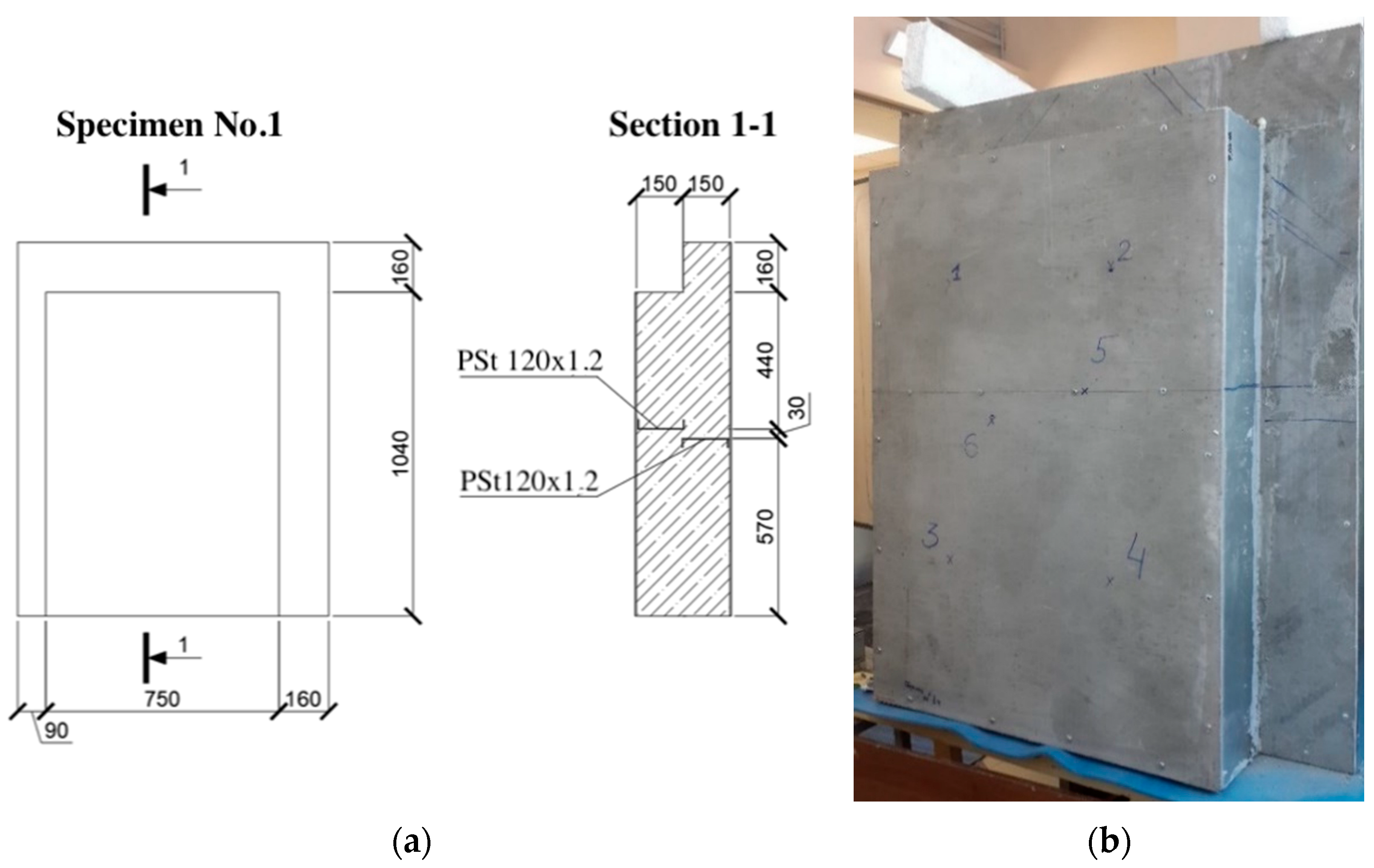
2.2. Research Model
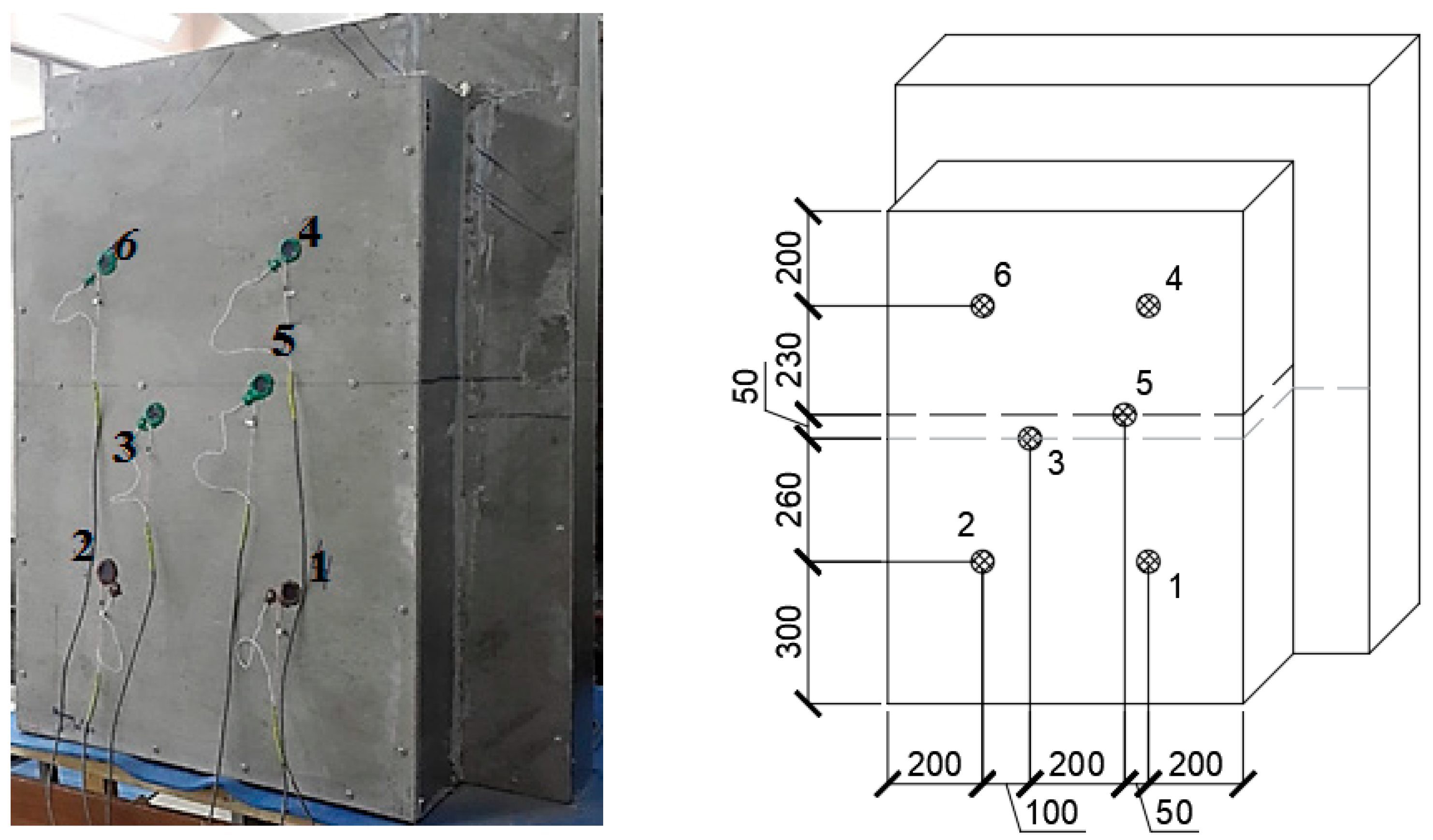
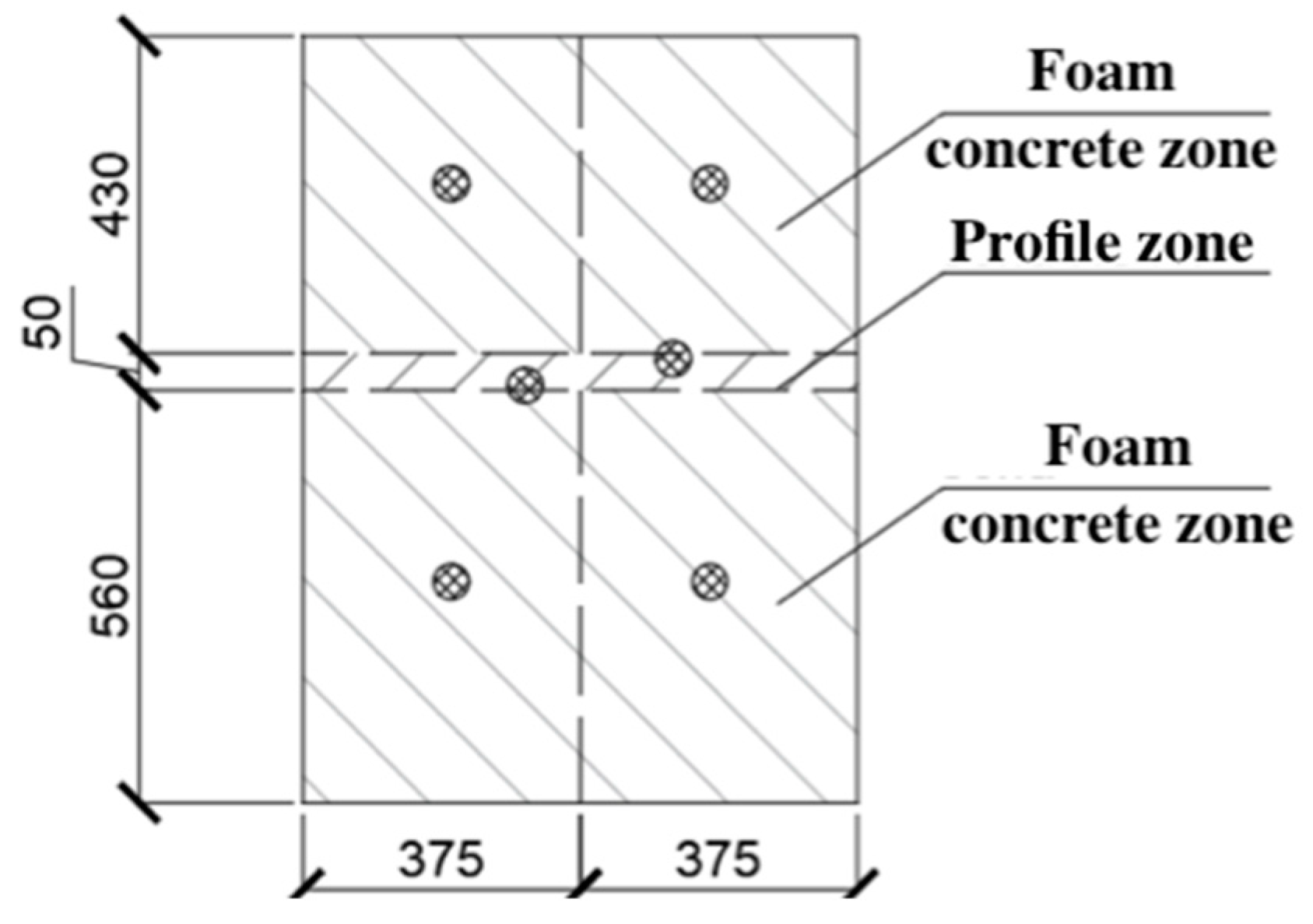
2.3. Methods
3. Results and Discussion
3.1. Determination of the Wall Panel Thermal Properties
3.2. Determination of the Reduced Total Thermal Resistance of Lightweight Steel Concrete Structures at Different Foam Concrete Moistures
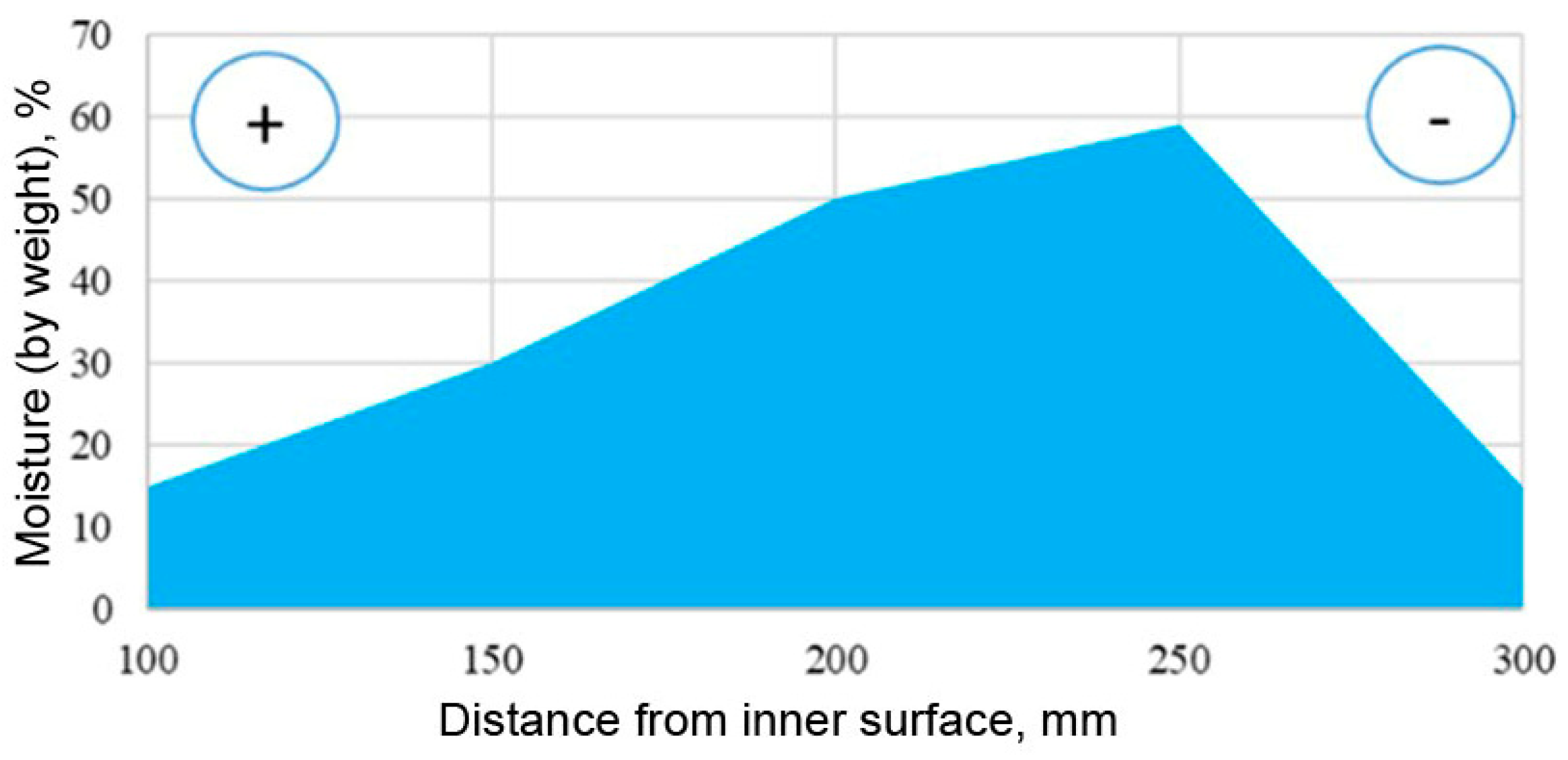
3.2.1. Determination of Foam Concrete Actual Moistures
3.2.2. Determination of the Reduced Total Thermal Resistance at Equilibrium Moisture Content of 8%
3.2.3. Determination of the Reduced Total Thermal Resistance in Dry State
3.2.4. Determination of the Reduced Total Thermal Resistance under High-Humidity Conditions
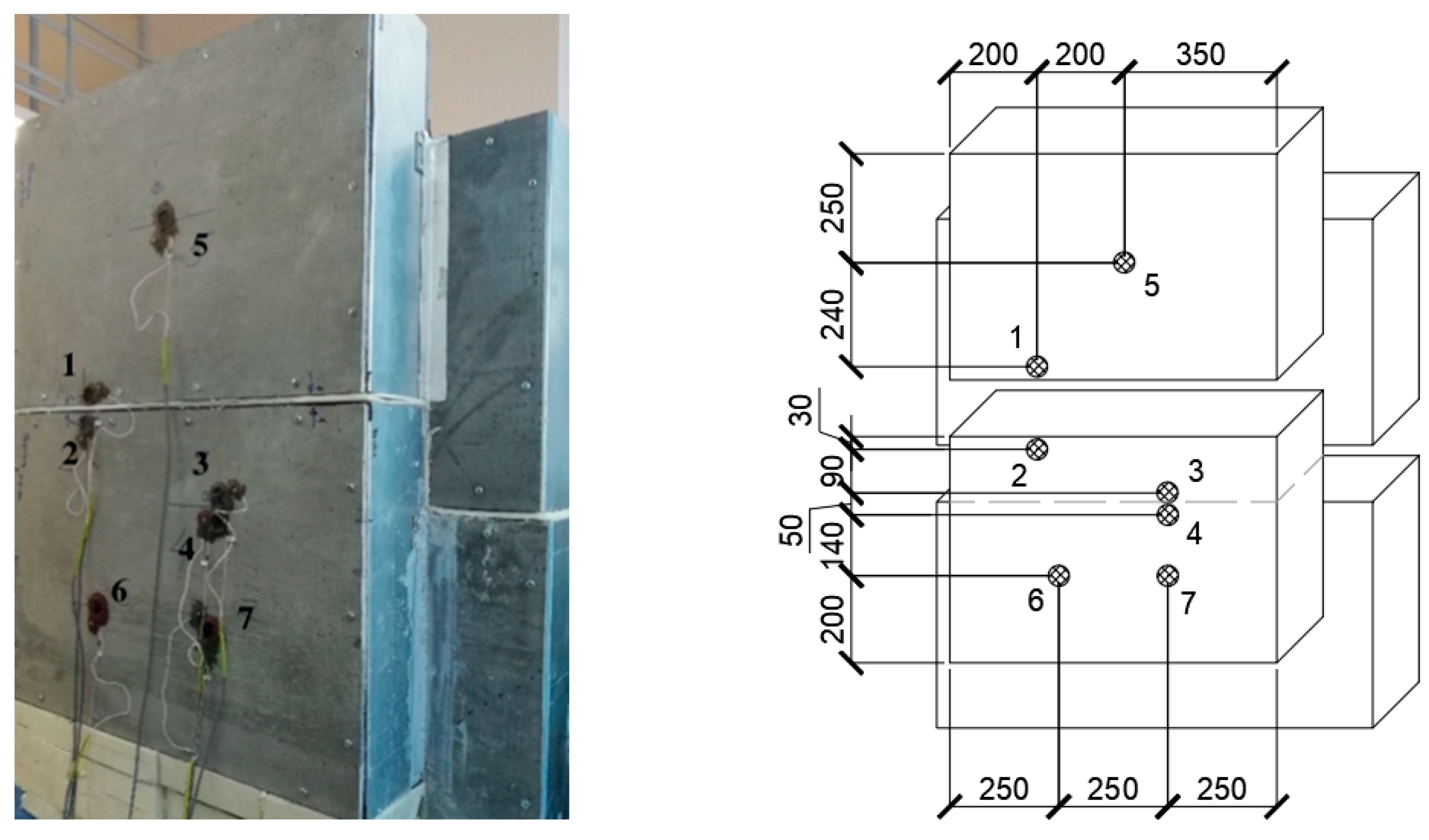
3.3. Determination of the Thermal Properties of Structure with Horizontal Joint and under High Humidity Conditions
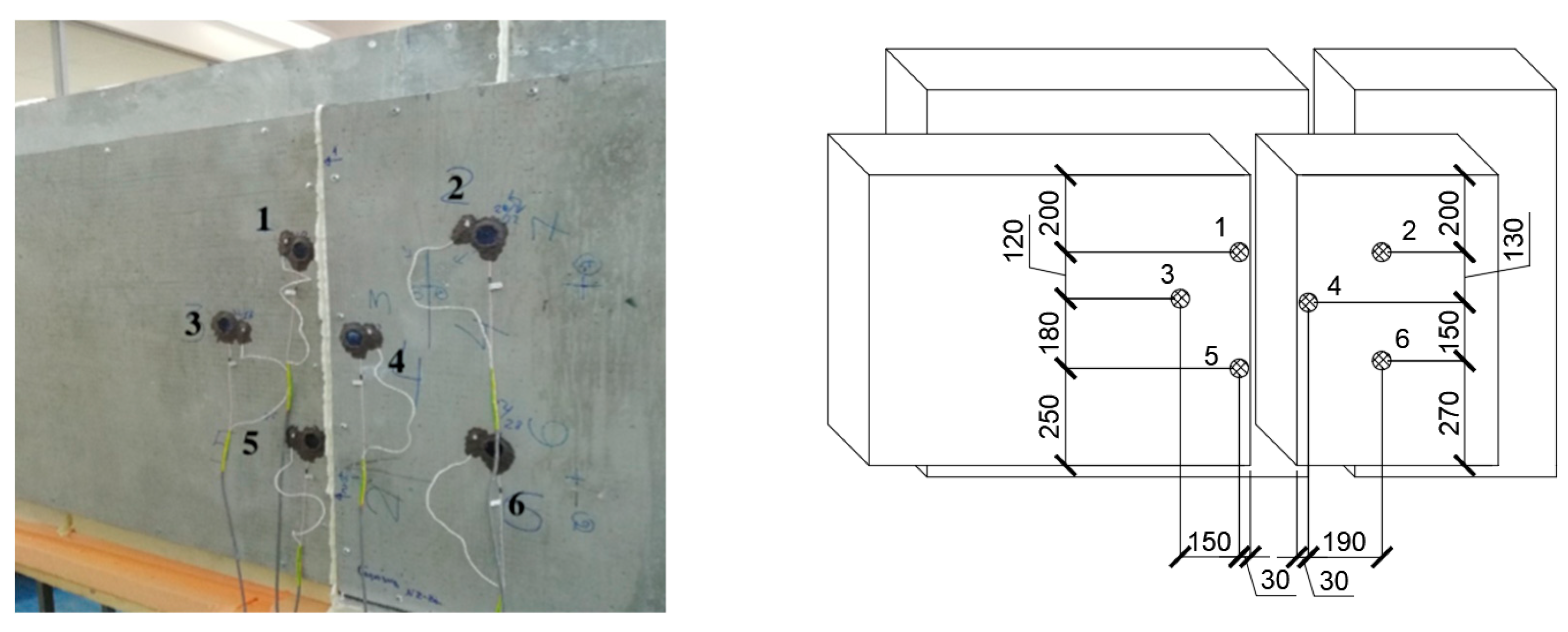
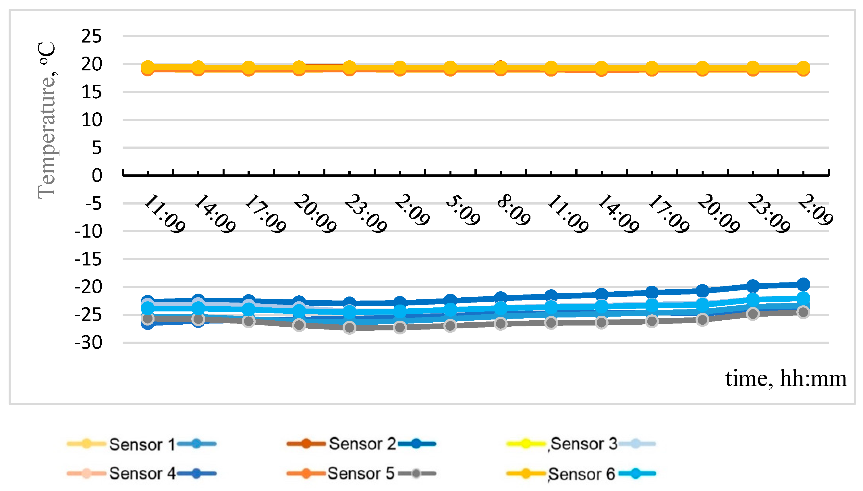
3.4. Determination of the Thermal Properties of Structure with Vertical Joint and under High-Humidity Conditions
4. Conclusions
- The total thermal resistance (considering thermal inhomogeneity) of the enclosing lightweight steel concrete structure with a thickness of 310 mm using monolithic low-density foam concrete (density grade of D200), at an equilibrium humidity of 5% and 8%, was established by calculation based on experimental data. It was equal to 4.602 m2.0 K/W and 4.1 m2.0 K/W, respectively, which corresponds to U-values equal to 0.217 W/m2.0 K and 0.244 W/m2.0 K, respectively.
- In the dry state, the total thermal resistance of this structure was 5.59 m2.0 C/W, which corresponds to a thermal conductivity coefficient of 0.057 m °C/W and U-value equal to 0.179 W/m2.0 K.
- The influence of both horizontal and vertical joints of lightweight steel concrete wall panels and the absence of thermoprofiles on thermal properties was insignificant when using heat-insulating gaskets.
- The presence or absence of perforation in the steel profile of lightweight steel concrete wall panels did not significantly affect their thermal properties.
- The total thermal resistance (considering thermal inhomogeneity) of the considered structure at an increased humidity of 29% and 32% was established by calculation based on experimental data. It was equal to 4.43 m2.0 K/W and 4.33 m2.0 K/W, respectively, which corresponds to U-values of 0.226 W/m2.0 K and 0.231 W/m2.0 K, respectively.
- The actual total thermal resistance of the structure was 2.5–2.8 times higher than that obtained by calculation based on experimental data under high-humidity conditions (29–32%). At the same time, the decrease in the value compared to the same value at an equilibrium humidity of 5% was only 4–6%. This indicates good workability even of a structure with high-humidity foam concrete if the reduced total thermal resistance is complied with by the standardized one.
Author Contributions
Funding
Institutional Review Board Statement
Informed Consent Statement
Data Availability Statement
Conflicts of Interest
References
- Rybakov, V.; Seliverstov, A.; Vakhidov, O. Fire resistance of lightweight steel-concrete slab panels under high-temperature exposure. In E3S Web of Conferences; EDP Sciences: Les Ulis, France, 2021; Volume 264, p. 02003. [Google Scholar]
- Yang, Z.H.; Guo, P.L.; Chen, X.; Jiang, W. Heat and humidity performance of EPS and Rock wool board external thermal insulation system. In IOP Conference Series: Materials Science and Engineering; EDP Sciences: Les Ulis, France, 2019; Volume 592, p. 012008. [Google Scholar]
- Wu, Z.; Li, J.; Ding, Y.; Dong, J.-L.; Yang, T.-L.; Romanova, I. The selecting of building insulation material by the analytic hierarchy process. In IOP Conference Series: Materials Science and Engineering; EDP Sciences: Les Ulis, France, 2018; Volume 365, p. 032016. [Google Scholar]
- Zimele, Z.; Sinka, M.; Bajare, D.; Jakovics, A. Life cycle assessment for masonry exterior wall assemblies made of traditional building materials. In IOP Conference Series: Materials Science and Engineering; EDP Sciences: Les Ulis, France, 2019; Volume 660, p. 012042. [Google Scholar]
- Rybakov, V.; Seliverstov, A.; Usanova, K.; Rayimova, I. Combustibility of lightweight foam concrete based on natural protein foaming agent. In E3S Web of Conferences; EDP Sciences: Les Ulis, France, 2021; Volume 264, p. 05001. [Google Scholar]
- Kazaryan, R.R.; Khvan, V.A. Technological Processes for Manufacturing Cellular Concrete Products for Construction. Mater. Sci. Forum 2018, 931, 634–639. [Google Scholar] [CrossRef]
- Bartenjeva, E. The effect of mineral additives on foam concrete porosity. In IOP Conference Series: Materials Science and Engineering; EDP Sciences: Les Ulis, France, 2020; Volume 962, p. 022023. [Google Scholar]
- Bartenjeva, E. The increase of heat-insulating properties of foam concrete by introducing mineral additives. In IOP Conference Series: Materials Science and Engineering; EDP Sciences: Les Ulis, France, 2018; Volume 456, p. 012036. [Google Scholar]
- Mashkin, N.; Bartenjeva, E. Research of structuring processes of non-autoclave foam concrete with introduction of mineral additives. In IOP Conference Series: Materials Science and Engineering; EDP Sciences: Les Ulis, France, 2018; Volume 451, p. 012018. [Google Scholar]
- Begich, Y.E.; Klyuev, S.V.; Jos, V.A.; Cherkashin, A.V. Fine-grained concrete with various types of fibers. Mag. Civ. Eng. 2020, 97, 9702. [Google Scholar]
- Klyuev, S.V.; Khezhev, T.A.; Pukharenko, Y.V.; Klyuev, A.V. To the Question of Fiber Reinforcement of Concrete. Mater. Sci. Forum 2019, 945, 25–29. [Google Scholar] [CrossRef]
- Gervásio, H.; Santos, P.; Simões da Silva, L.; Lopes, A.M.G. Influence of thermal insulation on the energy balance for cold-formed buildings. Adv. Steel Constr. 2010, 6, 742–766. [Google Scholar]
- Amran, Y.H.M.; Farzadnia, N.; Ali, A.A.A. Properties and applications of foamed concrete; a review. Constr. Build. Mater. 2015, 101, 990–1005. [Google Scholar] [CrossRef]
- Wagh, C.D.; Indu Siva Ranjani, G.; Kamisetty, A. Thermal Properties of Foamed Concrete: A Review. In International Conference on Innovative Technologies for Clean and Sustainable Development, Proceedings of the ITCSD 2020: 3rd International Conference on Innovative Technologies for Clean and Sustainable Development, Chandigarh, India, 19–21 February 2020; Springer: Cham, Switzerland, 2021; Volume 29, pp. 113–137. [Google Scholar]
- Barteneva, E.A.; Ylesin, M.A.; Mashin, N.A.; Dubrov, D.V. Improvement of Heat-Insulating Properties of Foam Concrete by Means of Mineral Additives. Key Eng. Mater. 2018, 771, 31–36. [Google Scholar] [CrossRef]
- Kudiakov, A.; Prischepa, I.; Tolchennickov, M. Foam concrete with porous mineral and organic additives. IOP Conf. Ser. Mater. Sci. Eng. 2015, 71, 012016. [Google Scholar] [CrossRef] [Green Version]
- Barabanshchikov, Y.; Usanova, K.; Akimov, S.; Uhanov, A.; Kalachev, A. Influence of electrostatic precipitator ash “zolest-bet” and silica fume on sulfate resistance of Portland cement. Materials 2020, 13, 4917. [Google Scholar] [CrossRef] [PubMed]
- Soares, N.; Martins, C.; Gonçalves, M.; Santos, P.; da Silva, L.S.; Costa, J.J. Laboratory and in-situ non-destructive methods to evaluate the thermal transmittance and behavior of walls, windows, and construction elements with innovative materials: A review. Energy Build. 2019, 182, 88–110. [Google Scholar] [CrossRef]
- Atsonios, I.A.; Mandilaras, I.D.; Kontogeorgos, D.A.; Founti, M.A. Two new methods for the in-situ measurement of the overall thermal transmittance of cold frame lightweight steel-framed walls. Energy Build. 2018, 170, 183–194. [Google Scholar] [CrossRef]
- Gorgolewski, M. Developing a simplified method of calculating U-values in light steel framing. Build. Environ. 2007, 42, 230–236. [Google Scholar] [CrossRef]
- Santos, P.; Gonçalves, M.; Martins, C.; Soares, N.; Costa, J.J. Thermal transmittance of lightweight steel framed walls: Experimental versus numerical and analytical approaches. J. Build. Eng. 2019, 25, 100776. [Google Scholar] [CrossRef]
- Santos, P. Energy Efficiency of Lightweight Steel-Framed Buildings. Energy Effic. Build. 2017, 35, 180–191. [Google Scholar]
- Santos, P.; Martins, C.; da Silva, L.S.; Bragança, L. Thermal performance of lightweight steel framed wall: The importance of flanking thermal losses. J. Build. Phys. 2014, 38, 81–98. [Google Scholar] [CrossRef] [Green Version]
- Roque, E.; Santos, P. The Effectiveness of Thermal Insulation in Lightweight Steel-Framed Walls with Respect to Its Position. Buildings 2017, 7, 13. [Google Scholar] [CrossRef] [Green Version]
- Leshchenko, M.V.; Semko, V. Thermal characteristics of the external walling made of cold-formed steel studs and polystyrene concrete. Mag. Civ. Eng. 2015, 60, 44–55. [Google Scholar] [CrossRef]
- Nocera, F.; Alonso González Lezcano, R.; Giuseppina Caponetto, R.; Li, T.; Xia, J.; Seong Chin, C.; Song, P. Investigation of the Thermal Performance of Lightweight Assembled Exterior Wall Panel (LAEWP) with Stud Connections. Buildings 2022, 12, 473. [Google Scholar]
- Rybakov, V.A.; Ananeva, I.A.; Pichugin, E.D.; Garifullin, M. Heat protective properties of enclosure structure from thin-wall profiles with foamed concrete. Mag. Civ. Eng. 2020, 94, 11–20. [Google Scholar]
- Vytchikov, Y.; Saparev, M.; Golikov, V. Application of monolithic foam concrete in building envelopes of a cottage, used in conditions of intermittent heating. In MATEC Web of Conferences; EDP Sciences: Les Ulis, France, 2018; Volume 196, p. 04015. [Google Scholar]


| Fragment Zone | Inner Surface Temperature, T2 [°C] | Outer Surface Temperature, T1 [°C] | Heat Flow, q [W/m2] | Apparent Thermal Resistance, R [m2·°C/W] |
|---|---|---|---|---|
| Foam concrete (bottom right zone) | −18.9 | 19.6 | 8.71 | 4.414 |
| Profile (zone of outer panel) | −22.5 | 19.5 | 16.39 | 2.56 |
| Foam concrete (top right zone) | −22.7 | 19.6 | 8.80 | 4.801 |
| Profile (zone of inner panel) | −22.9 | 19.9 | 26.46 | 1.597 |
| Foam concrete (top left zone) | −18.5 | 19.6 | 6.70 | 5.689 |
| Zone | Areas of Zone [m2] |
|---|---|
| Foam concrete zone (area above the profile) | 0.29625 |
| Profile zone | 0.0375 |
| Foam concrete zone (area below the profile) | 0.39375 |
| Total: | 0.7275 |
| Fragment Zone | Inner Surface Temperature, T2 [°C] | Outer Surface Temperature, T1 [°C] | Heat Flow, q [W/m2] | Apparent Thermal Resistance, R [m2·°C/W] |
|---|---|---|---|---|
| Foam concrete (upper zone) | −26.8 | 19.6 | 8.71 | 5.33 |
| Profile (zone of inner panel) | −24.6 | 19.3 | 33.86 | 1.328 |
| Profile (zone of outer panel) | −22.8 | 19.7 | 8.36 | 5.08 |
| Foam concrete (bottom left zone) | −29.5 | 19.6 | 11.04 | 4.452 |
| Foam concrete (bottom right zone) | −28.8 | 19.6 | 9.83 | 4.918 |
| Zone | Areas of Zone [m2] |
|---|---|
| Foam concrete zone (area above the profile) | 0.39 |
| Profile zone | 0.0375 |
| Foam concrete zone (area below the profile) | 0.2775 |
| Total: | 0.705 |
| Fragment Zone | Inner Surface Temperature, T2 [°C] | Outer Surface Temperature, T1 [°C] | Heat Flow, q [W/m2] | Apparent Thermal Resistance, R [m2·°C/W] |
|---|---|---|---|---|
| Foam concrete (left zone) | −23.4 | 19.35 | 8.559 | 4.995 |
| Profile (left zone) | −25.39 | 18.99 | 40.543 | 1.095 |
| Profile (right zone) | −25.14 | 19.07 | 33.98 | 1.301 |
| Foam concrete (right zone) | −22.72 | 19.38 | 8.267 | 5.093 |
| Foam concrete (left zone) | −23.4 | 19.35 | 8.559 | 4.995 |
| Zone | Areas of Zone [m2] |
|---|---|
| Foam concrete zone (left zone) | 0.28 |
| Profile zone | 0.042 |
| Foam concrete zone (right zone) | 0.28 |
| Total: | 0.602 |
Publisher’s Note: MDPI stays neutral with regard to jurisdictional claims in published maps and institutional affiliations. |
© 2022 by the authors. Licensee MDPI, Basel, Switzerland. This article is an open access article distributed under the terms and conditions of the Creative Commons Attribution (CC BY) license (https://creativecommons.org/licenses/by/4.0/).
Share and Cite
Rybakov, V.; Ananeva, I.; Seliverstov, A.; Usanova, K. Thermal Properties of Lightweight Steel Concrete Wall Panels under Different Humidity Conditions. Materials 2022, 15, 3193. https://doi.org/10.3390/ma15093193
Rybakov V, Ananeva I, Seliverstov A, Usanova K. Thermal Properties of Lightweight Steel Concrete Wall Panels under Different Humidity Conditions. Materials. 2022; 15(9):3193. https://doi.org/10.3390/ma15093193
Chicago/Turabian StyleRybakov, Vladimir, Irina Ananeva, Anatoly Seliverstov, and Kseniia Usanova. 2022. "Thermal Properties of Lightweight Steel Concrete Wall Panels under Different Humidity Conditions" Materials 15, no. 9: 3193. https://doi.org/10.3390/ma15093193
APA StyleRybakov, V., Ananeva, I., Seliverstov, A., & Usanova, K. (2022). Thermal Properties of Lightweight Steel Concrete Wall Panels under Different Humidity Conditions. Materials, 15(9), 3193. https://doi.org/10.3390/ma15093193