Abstract
Hybrid plasmas have been reported in various areas of research over the last 40 years. However, a general overview of hybrid plasmas has never been presented or reported. In the present work, a survey of the literature and patents is carried out to provide the reader with a broad view of hybrid plasmas. The term refers to several different configurations of plasmas, including but not limited to: plasmas driven by several power sources simultaneously or sequentially, plasmas that have the properties of both thermal and nonthermal plasmas, plasmas that are enhanced by additional energy, and plasmas that are operated in a unique medium. In addition, a way of evaluating hybrid plasmas in terms of the improvement of processes is discussed, as well as the negative impacts that follow the employment of hybrid plasmas. Regardless of what the hybrid plasma in question is composed of, it often poses a unique advantage to its nonhybrid counterpart, whether it be used for welding, surface treatment, materials synthesis, coating deposition, gas phase reactions, or medicine.
1. Introduction
Gas discharge plasmas are widely applied for materials processing due to their unique properties of reactivities, effectiveness, controllability, and environmental friendliness [1]. For example, plasmas can be applied in the following areas or industries: semiconductors, electronics, automotives, polymers, food, construction, mechanics, medicine, combustion, and energy. With regards to materials processing, plasmas can be used to functionalize surfaces of bulk materials and films as well as synthesize particles. In fact, it is difficult to find industrial areas in which plasmas are not used; plasmas are very useful since they can be used to process solids (bulk, materials, thin films, particles, etc.), liquids, and gases. There have been various attempts to further improve the properties of plasmas, as well as attempts that seek to discover and explore unknown effects.
The development of hybrid plasma is stimulated by these ventures [2], often operated at atmospheric pressure [3,4]. However, the technical term “hybrid plasma” has been used for several different types of technologies. The present paper reviews different types of hybrid plasmas for materials processing and discusses the scope of future developments. The term “hybrid plasma” can refer to a plasma driven by multiple different sources, a plasma having multiple unique properties simultaneously, or a plasma enhanced by additional energy such as photoirradiation, acoustic energy, or thermal energy. In addition, plasma operated in a unique medium rather than a gaseous phase can also be classified as a hybrid plasma.
Since the major motive of developing hybrid plasmas is to exhibit something that cannot be achieved by conventional plasma alone, it is natural that these plasmas are often associated with intellectual properties. There are many patents associated with hybrid plasmas filed and granted worldwide for decades. Due to the nature of intellectual properties, operating conditions are ambitiously defined. For example, it is often the case that hybrid plasmas described in patents are described to be operational at both low and atmospheric pressures, even if this is sometimes unrealistic; the hybrid plasmas in these patents do not necessarily demonstrate the proposed effects at both pressures. As a result, their descriptions can sometimes be inaccurate or incorrect. Nonetheless, useful information can be included, and thus, these patents should neither be underestimated nor neglected.
In the current paper, the following types of hybrid plasmas from academic publications and patents will be presented:
- -
- Plasmas driven by multiple different electrical sources simultaneously;
- -
- Plasmas driven by multiple different electrical sources sequentially;
- -
- Plasmas having properties of thermal and nonthermal plasmas;
- -
- Plasmas enhanced by additional energy;
- -
- Plasmas operated in a unique medium.
Furthermore, proposals and suggestions are made for the future of hybrid plasmas, and the advantages and disadvantages of hybrid plasmas are discussed.
2. Plasmas Driven by Multiple Different Electrical Sources Simultaneously
2.1. Combination of Two Plasmas
The technical term “hybrid plasma” was mentioned as early as 1983 [2], and this work by Yoshida et al. can therefore be counted among the earliest works to study hybrid plasmas. This hybrid plasma is described as the superposition of a radio-frequency (RF) plasma and an arc jet. The numerical model of the hybrid plasma predicts its higher efficiency than conventional plasmas. The experimental investigation based on the numerical model exhibits that the hybrid plasma enables the effective synthesis of ultrafine SiNx compounds [2].
Similarly, a mathematical model that simulates a plasma reactor, which combines direct current (DC) and RF plasmas for the production of silicon, finds that by coupling flow and temperature fields, both production and recovery of silicon become remarkably more efficient than for a purely DC or RF plasma reactor [5].
Saiki et al. propose a process for producing ultrafine metallic or metal compound particles using an apparatus comprised of a plurality of DC plasma sources with inductively coupled plasma (ICP) [6], as shown in Figure 1. Here, the DC plasma sources generate arc discharges to heat up the source material to synthesize the particles. The ICP is used to induce reactions of the synthesized particles with the surrounding reactive gas.
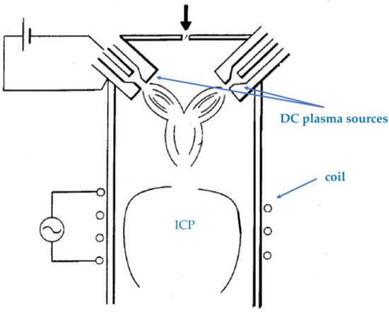
Figure 1.
A schematic diagram of an apparatus comprised of a plurality of DC plasma sources with ICP (based on [6]).
Both capacitively coupled plasma (CCP) and ICP can be generated using RF power supplies. Cho et al. propose a low-pressure plasma setup containing both operated by one generator, as shown in Figure 2 [7]. ICP can be generated in a space between powered and ground electrodes that constitute CCP. The proposed setup allows for high throughput productions for plasma etching and any other general plasma processing due to its simple design.
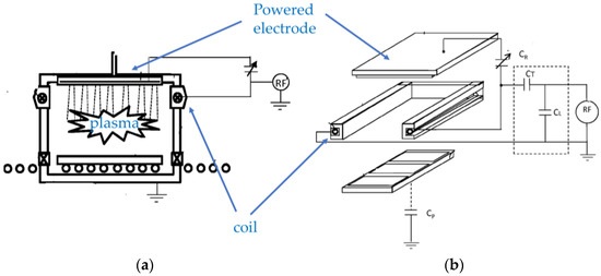
Figure 2.
Schematic diagrams of a low-pressure plasma setup. (a) A cross-sectional view of the setup; (b) A perspective view of the electrodes and coil configuration of the setup with RF generator and matching circuit (based on [7]).
Chen et al. [8,9] and Cui et al. [10] also propose the combination of ICP and CCP for semiconductor processing, as shown in Figure 3. The difference from [7] is that ICP is a remote plasma source. The plasma excited species generated at CCP with the aid of ICP is fed to the gas reaction region. A specimen is placed at the gas reaction region to be processed. When higher power operation is required, both plasmas can be used simultaneously so that CCP can be operated at lower power. This configuration can reduce the generation of unwanted contaminations from CCP electrodes.
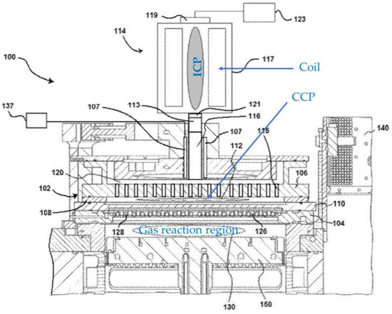
Figure 3.
A schematic diagram of a hybrid plasma setup comprised of a remote ICP and CCP (based on [8,9,10]).
Roppel et al. [11] propose a dual plasma microwave (MW) apparatus. It is a combination of DC or RF plasma with MW, as shown in Figure 4. A DC or RF plasma is generated by supplying DC or RF power to a platform on which a specimen to be treated is placed. A DC or RF plasma is generated above the specimen. Meanwhile, MW is introduced to generate MW plasma. By applying a bias, ions in the MW plasma can be extracted to interact with the DC or RF plasma. This configuration enables pronounced ignition of the DC or RF plasma as well as tuning and improving plasma treatment effects.
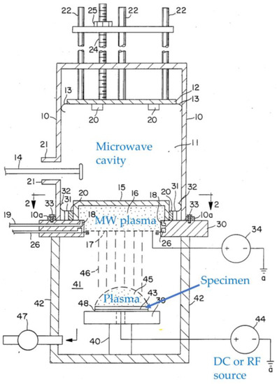
Figure 4.
A cross-sectional view of a hybrid plasma setup, where the lower part is a hybrid of MW plasma and DC or RF plasma depending on the way it is biased (based on [11]).
MW plasma and low-frequency (LF) plasma can be used in combination for plasma sterilization at atmospheric pressure [12]. It is discovered that the sterilization effects on spore-forming bacteria depend on the way the plasma gases are supplied [12].
Bárdoš et al. [13,14] propose a hybrid plasma configuration applicable for low-pressure processing (below 1 Pa) and for the generation of cold atmospheric pressure plasma, which can be used for thin film deposition or plasma surface treatment. The low-pressure hybrid plasma source combines an electron cyclotron resonance (ECR) plasma and a plasma generated by a hollow cathode, as shown in Figure 5. In the case of atmospheric pressure operation, efficient ECR is not expected due to significant collisions of electrons in the plasma. The plasma from the hollow cathode and MW plasma can be simultaneously generated to exhibit high plasma densities without the need for a magnetic field.
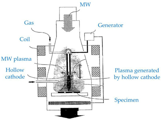
Figure 5.
A schematic diagram of a hybrid plasma setup comprised of a plasma generated by a hollow cathode and MW plasma in the presence of a magnetic field (based on [13]).
Choi [15,16] proposes a hybrid plasma reactor comprised of a ring-shaped transformer-coupled plasma with magnetic flux channel-coupled plasmas, to perform plasma processing for solids, powders, and gases. Figure 6 shows a sectional view of the hybrid plasma reactor. The transformer-coupled plasma is generated by delivering alternating current (AC) signals into the ring-shaped chamber (1st plasma chamber) by using a transformer, which is not illustrated in Figure 6. Although it is not clearly specified in the patent, both CCP and ICP can be generated in the first plasma chamber in this way. The hybrid plasma includes the magnetic flux channel-coupled plasmas. This configuration allows for a high control capability for plasma ion energy and a wide operation region from a low-pressure region to a high-pressure region.
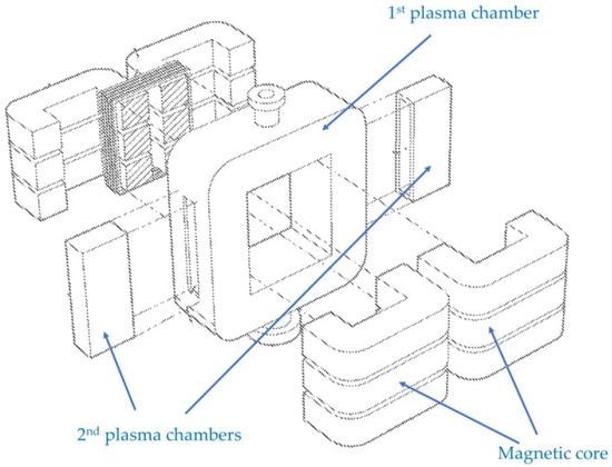
Figure 6.
A sectional view of a hybrid plasma reactor combining transformer-coupled plasma (1st plasma chamber) with magnetic flux channel coupled plasmas (2nd plasma chambers) (based on [15]).
Vaduganathan et al. [17] study ozone generation by using a combination of AC surface discharge and pulsed DC corona discharge at atmospheric pressure. They find that a positive corona with surface discharge exhibits more efficient ozone generation than a negative corona. In both cases, the improvement of ozone generation can be attributed to a larger reaction volume.
Dual cathode magnetron sputtering (DCMS) can also be regarded as a hybrid plasma. When two different metals are used for the targets, the synthesis of alloy films can be conveniently studied since each target can be operated independently. One example is the deposition of boron–carbon–nitride (BCN) films using DCMS [18], in the expectation that this will result in growth of cubic-BCN which has a structure like a diamond or cubic boron nitride. However, the results indicate that the introduction of boron is often difficult even with DCMS. DCMS can be used not only for alloy synthesis but also for improving the performance of magnetron sputtering. Specifically, by facing the magnetron targets with each other and arranging the configuration of the closed magnetic field in between, ion bombardment to the substrates and the growing film can be significantly improved [19].
Kong et al. [20] propose a hybrid plasma source combining two arc discharges, as shown in Figure 7. The first arc is used to ionize a hydrocarbon gas. The gas is subsequently fed to a second plasma source. Water is introduced between the arcs, and the second arc activates water to generate activated hydrogen and oxygen. The ionized hydrocarbon gas is reacted with the activated hydrogen and oxygen to generate synthetic gas. A plurality of arc sources can also be combined to produce synthetic gas [21], as shown in Figure 8.
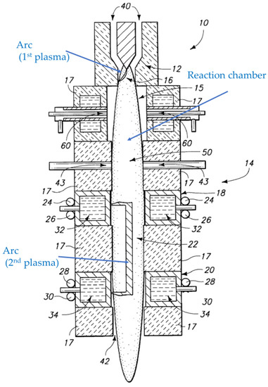
Figure 7.
A cross-sectional view of a hybrid plasma reactor combining two arc plasmas (based on [20]).
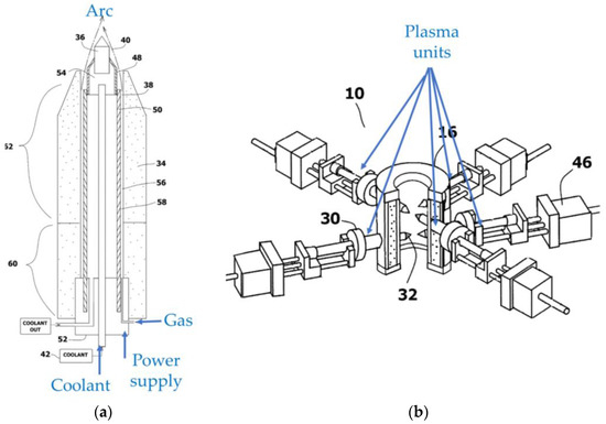
Figure 8.
Schematic diagrams of a hybrid plasma source using a plurality of arc plasma sources. (a) A single plasma unit. (b) An assembled plasma source combining the plasma units (based on [21]).
2.2. Ionized Magnetron Sputtering and Electron Cyclotron Resonance Magnetron Sputtering
One of the most successful uses of hybrid plasmas in this category from the late 1990s and early 2000s is in ionized magnetron sputtering (IMS) for thin film deposition, although it is never referred to as such. Magnetrons are used to sputter atoms against a target surface, and this technology has been praised as a step forward in sputtering technology [22]. However, the magnetron sputtering process can be improved further by increasing the ion bombardment flux to the film deposited on the substrate, by generating an ICP after the magnetron plasma to ionize the sputtered atoms [22]. Figure 9 shows a schematic diagram of a typical IMS setup. ICP is usually generated in a space between the magnetron and the substrate. If the substrate is biased, the ions can be accelerated toward the substrate so that a dense coating can be deposited, and the impact of collision of the ion to the film is greater as the potential difference is greater.
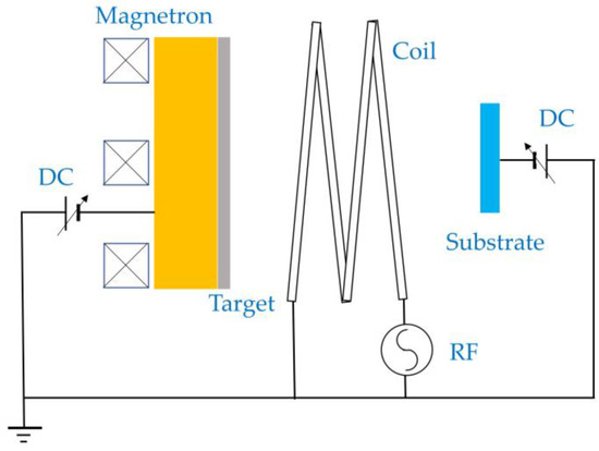
Figure 9.
A schematic diagram of an ionized magnetron sputtering system.
Chen et al. [23] demonstrate improved crystallinity and low resistivity of tungsten films using an IMS. Chiu et al. [24,25] use IMS for stress control and texture formation of silver films, showing that the product of the ion flux and ion energy is the controlling parameter for texture formation. Tranchant et al. [26,27] present similar investigations to Chui et al. for MoCr films. Christou et al. [28] find that ionization of sputtered atoms strongly depends on the pressure of the sputtering gas. Schneider et al. [29,30] demonstrate low-temperature deposition of alumina using IMS.
While efficient ionization and subsequent effects are demonstrated for metal depositions, carbon and carbon nitride films are also deposited using IMS in the application of hard and tribological coatings. Kusano et al. [31] find that positive substrate bias on the substrates showed higher sp and sp2-hybridized carbon contents than those without ICP and/or with negative bias voltages related to the selective etching of nitrogen and sp and sp2-hybridized carbon. The results are associated with the tribological properties of carbon nitride films [32]. The effects of using different inert gases, including helium, neon, and krypton, are also reported [33]. Angleraud et al. [34,35] also study the synthesis of carbon nitride films using IMS, finding selective areal deposition of carbon nitride on conductive and insulating parts of substrates.
In a similar way, electron cyclotron resonance magnetron sputtering (ECR-MS) can also be considered a hybrid plasma. According to Yoshida [36] and Xu et al. [37], ECR-MS can be operated at 0.007 Pa. The electron cyclotron frequency and MW frequencies are synchronized to achieve resonance, hence the classification of ECR-MS as a hybrid plasma. It is noted that at higher pressures, collisions are pronounced to prevent efficient ECR acceleration. As a result, ECR-MS is most effective for pressures between 0.001 and 1 Pa [38]. When the pressure is higher than 0.1 Pa, wave damping by collisions is reported [39]. Therefore, ECR-MS is attractive for applications requiring low-pressure sputter depositions.
IMS and ECR-MS are developed to enhance ionization of the plasma in the magnetron environment. This aim can also be achieved by supplying a DC-pulsed voltage of high energy density to the magnetron without hybridization. This technique is called high-power impulse magnetron sputtering (HIPIMS), also called high power pulsed magnetron sputtering (HPPMS) [40,41,42]. Due to the use of the pulsed high-voltage excitation, high ionization fraction of the sputtered species is expected. However, it is beyond the scope of this review, and hence a detailed description is not provided.
2.3. Superposition
In Section 2.1 and Section 2.2, hybrid plasmas that are created by generating two or more plasmas simultaneously were discussed. However, processing using a single plasma can be improved by superposing different frequencies and/or waveforms of excitation voltages to generate and sustain a plasma. This type of plasma can also be regarded as a hybrid plasma.
Ito et al. [43] report the synthesis of superconducting films by using a magnetron sputtering system, in which RF voltage is superimposed on a DC voltage. This sputtering method is called hybrid plasma sputtering or hybrid plasma magnetron sputtering.
This technique enables the formation of superconducting films with high crystallinity due to the RF plasma, while achieving high-speed deposition due to the DC plasma. A setup of the hybrid plasma sputtering is illustrated in Figure 10, presented by Yoshida et al. [44].
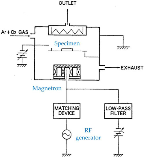
Figure 10.
Hybrid plasma sputtering (based on [44]).
It is reported that superposing different frequencies and/or waveforms of voltages is effective at producing ozone (for example [45]), similar to the pulsed excitation of the plasma [46]. Ahn et al. [45] combine AC-driven surface discharge with a pulsed DC corona discharge to demonstrate improved ozone production yield.
It is noted that this type of technique is often referred to as “superimposition”. However, “superposition” is the proper technical term to be used.
3. Plasmas Driven by Multiple Electrical Sources Sequentially
One interpretation of hybrid plasmas is “the use of two plasma sources in the same vacuum chamber for two different applications” [47]. Alim et al. [47] refer to this as duplex surface treatment, and in their application, they utilize an ICP source and a magnetron cathode. The former is used to nitride and activate a given surface, while the latter is utilized for titanium deposition onto the surface.
Duplex surface treatment is also used to improve tribological characteristics of metals; Díaz-Guillén et al. use pulsed plasma nitriding and a postoxidizing process to treat both hot work H13 tool steel [48] and cold work AISI D2 tool steel [49]. Researching such treatment for the latter material is especially important, considering its brittleness and wear rate; after the duplex surface treatment, the wear resistance is improved drastically because of the protective properties of the newly oxidized layer.
It can be noted that hybrid plasmas are tools often used for surface strengthening. Treating Ti6Al4V with a combination of plasma immersion ion implantation with ion nitriding processes improves the hardness of this alloy considerably [50].
Another example is the deposition of Ti by magnetron sputtering followed by DLC coating using acetylene by hybrid plasma-activated metal–organic vapor deposition/physical vapor deposition (PA-MOCVD/PVD) [51] to synthesize hard coating for dental application. The technique has the disadvantage of using a single RF generator for the deposition of Ti and DLC with a risk of carbon contamination of the reaction chamber.
Hseih et al. [52] propose a roll-to-roll hybrid plasma modular coating system, which is comprised of at least one arc plasma processing unit and a magnetron sputtering unit, as shown in Figure 11. A web substrate is continuously fed to the arc plasma zone to pretreat the surface, and subsequently, a coating is deposited onto the activated surface by the magnetron sputtering.
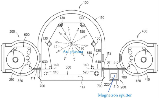
Figure 11.
A schematic diagram of a roll-to-roll hybrid plasma modular coating system (based on [52]).
Although the above examples in this section are claimed as hybrid plasmas, they are most suitably regarded as two-step processes.
4. Plasmas Having Properties of Thermal and Nonthermal Plasmas
Simultaneously achieving high chemical selectivity and efficient productivity is a challenge for atmospheric pressure plasma processing [3,4]. Nonthermal plasmas at a nonequilibrium state ensure elective chemical processes influence the chemical bonding of the molecules in the plasma and/or at the material surfaces to be treated. On the other hand, thermal plasmas, often characterized by high energy densities, enable efficient productivity. However, high nonequilibrium states with high energy densities are hard to achieve by general nonthermal plasmas or thermal plasmas. Therefore, the prospective of a plasma processing method that, by combining thermal and nonthermal plasmas possesses the advantages of both, is attractive. The gliding arc is one such type of plasma and is categorized as a hybrid plasma [1,53]. Note that while the gliding arc is technically a single plasma, the fact that it possesses the properties of both thermal and nonthermal plasmas is the reason that it is classified as hybrid. In this sense, perhaps it should be considered a separate kind of hybrid plasma.
The gliding arc is shown to have many important applications, such as the cleaning of gas and controlling pollution, the conversion of fuel, and the production of hydrogen [1,53]. Gliding arcs also enhance combustion [54] and demonstrate sterilization effects [55]. Extensive research has been conducted on surface treatment for adhesion improvement using gliding arcs [56,57,58,59,60,61]. For example, wettability and adhesive strength of polyester composite plates with an adhesive (vinylester resin) are significantly improved, and as a result, the laminated structure of polyester composite and vinylester demonstrate significant fracture resistance [57,58]. The major treatment effect is attributed to the oxidation of the polyester [56,57,58,59,60,61].
Plasma diagnostics of the gliding arc have been extensively carried out and reported mainly by capturing photo images, using optical diagnostics and electric measurements. A typical gliding arc is a plasma column that is generated as an arc discharge and extends between two diverging electrodes in a turbulent gas flow.
The gliding arc is generally visualized as a thick photoemitting region. The upper images of Figure 12 show photos of AC-driven gliding arcs with different air flowrates [62]. However, true dynamic behaviors of gliding arcs are favorably observed by high-speed charged-coupled device (CCD) cameras with short exposure times [54,63,64,65,66,67,68,69,70,71,72]. Photos of gliding arcs observed by CCD cameras are shown in the lower images of Figure 12. The gliding arc is a thin plasma column. A typical evolution of a gliding arc is shown in Figure 13. The plasma column elongates until its extinction or until it encounters short-cutting events.
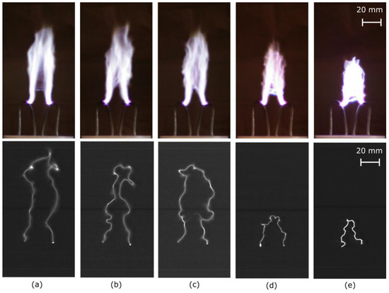
Figure 12.
Photos images of the gliding arc I at air flowrates of: (a) 14 standard liter per minute (SLM), (b) 17.5 SLM, (c) 21 SLM, (d) 31.5 SLM, and (e) 42 SLM. The upper images: acquired by a normal camera using an automatic exposure time. The lower images: captured by a high-speed camera using an exposure time of 13.9 μs. Reproduced with permission from [62] Kusano et al., Eur. Phys. J. D.; published by Springer Nature, 2014.
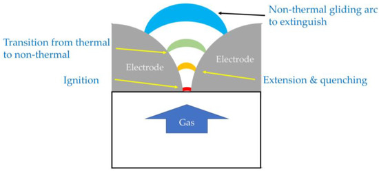
Figure 13.
Gliding arc evolution.
Voltage-current (VI) characteristics are often researched since their measurement gives direct information on ignition, short-cutting events, power consumption, evolution, and fluctuation of gliding arcs [63,64,65,66,67,69,70,72,73,74,75,76,77,78,79,80].
Optical emission spectroscopy (OES) is widely used for plasma diagnostics. It is regarded as an ideal noninvasive technique that does not contaminate the plasma environment. OES of gliding arcs is reported for studying reactive species in the plasma such as excited-state OH radicals and NO radicals, as well as estimating rotational and vibrational temperatures of gliding arcs [71,73,74,81,82,83,84,85]. It is noted that OH radicals are known to be highly oxidative agents, and that photoemission of OH radicals is detected even 60 mm away from the edge of the electrodes [56]. The result indicates that the gliding arc can be advantageously applied for surface modification of 3D bulky objects for adhesion improvements [56].
Laser-induced fluorescence (LIF) can be employed to measure distribution of the ground-state OH, which does not emit photons by itself. Figure 14 exemplifies LIF images at the vicinity of a gliding arc [67]. The detected ground-state OH exhibits a hollow structure around the plasma column. It is therefore indicated that the ground-state OH can be generated by the decay of the excited OH that is detected in the discharge column by OES.
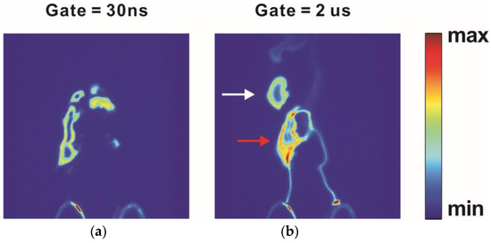
Figure 14.
LIF images captured with two gate times of (a) 30 ns (LIF signal only) and (b) 2 μs (both LIF signal and plasma column emission). Both the red and white arrow in (b) indicate ground state OH. Adapted with permission from [67] © The Optical Society.
In addition to the observations and characterizations of gliding arcs by plasma diagnostics, theoretical studies are reported in terms of energy balance [1,53,86,87,88,89,90,91] and force balance [66,92]. Furthermore, equivalent electric circuits are proposed for studying gliding arcs [1,53,62]. The plasma string model [89,90,91] is regarded as an energy balance equation of the equilibrium gliding arc [1,53], taking a small part of the plasma column and neglecting radial convection or turbulent effects. The Elenbass–Heller equation is regarded as a simplified governing equation of a gliding arc [93], which can accurately describe the electrical field, electrical conductivity, temperature, and plasma column radius of the gliding arc.
It is desirable for many industrial applications that a gliding arc does not extinguish in a short time after ignition and is sustained as the nonthermal gliding arc. This is so that the energy introduced to the gliding arc can be used efficiently. Otherwise, a significant amount of energy is consumed for reignition. Therefore, studying stability, fluctuations, and thermal to nonthermal transition of gliding arcs is important for better controlling the gliding arcs. Ref. [62] reports an analytical calculation based on Ohm’s law for studying the critical length of AC gliding arc discharge columns. The study indicates that the critical length of the AC gliding arc can be larger than that of a DC gliding arc. The analysis further shows that the critical length can be increased by increasing the AC frequency for driving the gliding arc, decreasing the serial resistance connected to the gliding arc electrode, and reducing the gas flowrate (Figure 12). The predicted dependence of air flowrate on the length of the gliding arc is experimentally demonstrated in [62].
5. Plasmas Enhanced by Additional Energy
5.1. Combination with Thermal Energy
Plasmas whose performances are enhanced by additional energy are also frequently referred to as hybrid plasmas.
Welding is a process that benefits from the use of these hybrid plasmas. The combination of a concentrated plasma arc and a “metal active gas” (MAG) has been found to be a more favorable replacement to traditional welding methods, since it is more efficient, has less weld metal content, and requires less preparation of welded metal joints [94]. Hybrid plasma arc welding has also been seen to reduce the weld width by 25–50% compared to the more traditional plasma arc welding, while keeping the energy output the same [95].
Furthermore, the combination of a hybrid plasma arc and micro rolling (HPAMR) technology have been used to coat Inconel 718 superalloy, often used in areas such as aviation. Due to the rolling process, this combination leads to an improvement in wall morphology of the coating, refinement of internal grains, elimination of defects and microporosity, an increase in the precipitation of the strengthening phase, and an improvement of the mechanical properties, much more so than plasma arc additive manufacturing [96].
Plasma MIG, which is hybrid plasma arc welding with gas–metal arc welding in a single torch, is more effective than the traditional pulsed MIG process since plasma can preheat and stabilize the MIG arc [97].
Another example of combining plasma with heat is the amalgamation of dielectric barrier discharge (DBD) plasma with external heating, resulting in a two-stage hybrid plasma–thermal system (HPTS) that shows promise in converting methane to ethylene and hydrogen [98].
5.2. Combination with Electron Beam
Hybrid plasma of this nature can also be applied in other ways, such as in the realm of medicine and biology. Upon exposure to oxygen hybrid plasma with the assistance of electron beams (EB), it is found that the hydrophilic tendencies of thin chitosan films are greatly improved for a period of nearly 50 days [99]. Additionally, it is noted that hybrid plasma can be used as a reliable bactericide and sterilizer, in comparison to oxygen RF plasma [99]. In this research, the main ionizer was an EB, while the other ionization source was an RF discharge [99].
Chen et al. [100] also combine an EB source with RF plasma, as shown in Figure 15. The introduction of EB assists ignition and sustainment of the plasma, as well as controlling the plasma properties. Laser-accelerated EB can also be used to power a plasma accelerator, which makes studies with such devices far easier at commonly available high-power laser facilities [101].
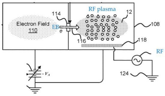
Figure 15.
A schematic diagram of a hybrid plasma setup combining an EB source with RF plasma (based on [100]).
5.3. Combination with Photoexcitation
Plasma processing can also be further activated by photoexcitation, for which laser sources are commonly used. Varghese et al. [102] propose a skin treatment device using an atmospheric pressure plasma, to which a laser beam is irradiated to facilitate the plasma treatment, as shown in Figure 16.
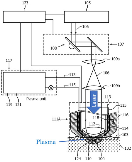
Figure 16.
A schematic diagram of laser-activated atmospheric pressure plasma (based on [102]).
Bayer et al. [103] combine MW plasma with laser irradiation for welding application, as shown in Figure 17. There are two configurations presented. One is similar to [102] where the directions of the MW plasma and the laser beam are coaxially aligned (Figure 17a). Another configuration is that the laser beam is directed at an angle to the MW plasma (Figure 17b). It is functionally the same as Figure 17a, but the advantage of this configuration is that the parts can be produced separately.
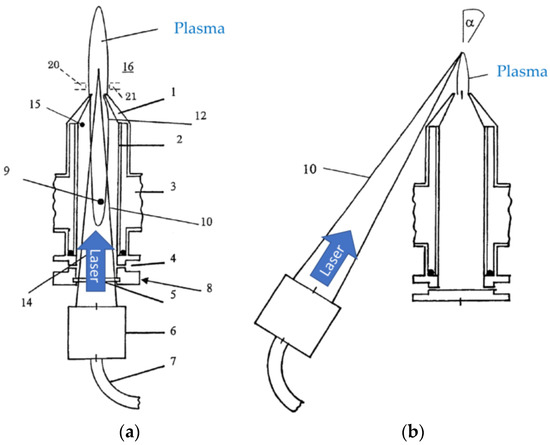
Figure 17.
Schematic diagrams of laser-activated atmospheric pressure MW plasma. (a) The directions of the MW plasma and the laser beam are coaxially aligned. (b) The laser beam is directed at an angle to the MW plasma (based on [103]).
5.4. Combination with Acoustic Energy or Mechanical Vibration
During atmospheric pressure plasma processing, a process gas is usually fed to the plasma. However, even when the gas flow is fully turbulent, a gas boundary layer sticks at the surface of the material that is to be treated with plasma. Plasma reactive species such as ions, electrons, high-energy neutrals, and radicals diffuse through the gas boundary layer and activate and/or react with the material surface. Since these reactive species generally have short lifetimes, only a small fraction of them can reach the material surface. It is reported that ultrasonic waves with a sound power level (SPL) above approximately 140 dB can reduce the thickness of the gas boundary layer and that the pressure plasma treatment can be made highly efficient by simultaneously irradiating ultrasonic waves to the treating surface [104,105,106,107,108,109,110,111,112]. This is because the acoustic energy can be delivered efficiently at high gas pressures, which reduces the thickness of the gas boundary layer, as shown in Figure 18.
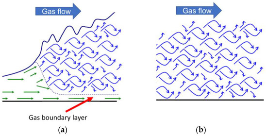
Figure 18.
A gas boundary layer (green) (a) without ultrasound and (b) with ultrasound (based on [112]).
As a result, the probability of the plasma reactive species reaching the surface before inactivation is higher when ultrasonic waves are applied, which improves surface modification efficiency. Combinations of a plasma and ultrasonic waves are investigated for understanding the interaction between plasma and acoustic waves [113,114,115], electrical discharge machining [116,117], plasma etching [118], ozone production [119,120,121,122], decomposition of volatile organic compounds (VOC) [123], charging performance improvement of corona chargers [124], and surface modification [104,105,106,107,108,109,110,111].
Ultrasonic-assisted electrical discharge machining combines ultrasonic waves with plasma using a solid-state electroacoustic transducer to vibrate material surfaces. However, due to the significant acoustic impedance mismatch between a solid material and a gas, most of the acoustic power generated by a solid-state transducer cannot be efficiently transmitted into the surrounding gas. Therefore, the thickness of the gas boundary layer at a material surface cannot be reduced efficiently. On the other hand, a gas jet ultrasonic generator excites acoustic waves in a gas and is suitable to eliminate or reduce the gas boundary layer. Figure 19 exemplifies a setup of an ultrasound-enhanced hybrid plasma. Ultrasonic waves are introduced to the plasma volume using a waveguide. A membrane can be used to separate the plasma gas from the ambient air. A mesh electrode is used as the upper electrode so that the ultrasound can pass it without a significant loss of acoustic energy. In this example, a gas jet ultrasonic generator is used.
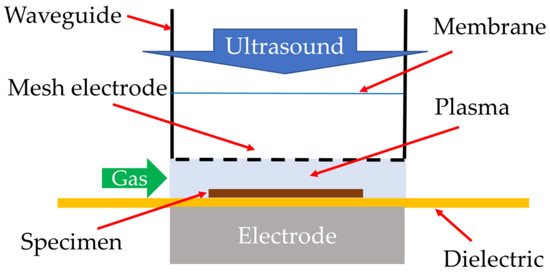
Figure 19.
A schematic diagram of ultrasound-enhanced plasma.
Plasma etching can also be enhanced with ultrasonic vibrations. Here, the surface to be treated is vibrated mechanically. These vibrations increase the plasma collision energy since the vertical vibration in the plasma leads to a relative speed enhancement of the particles in the plasma. The incident angle of particles and the energy at which they collide are also increased. The increase in collision angle leads to better anisotropy in plasma etching, while the energy increase results in an improvement of the etch rate [118].
6. Plasmas Operated in a Unique Medium
There is a growing interest in operating plasmas in different mediums, expecting new results for material synthesis, processing, and reaction fields. Examples of such plasmas include plasmas generated in a packed catalyst, plasmas generated in a liquid, and plasmas generated in a supercritical fluid.
The study of plasma catalysis has recently been growing in popularity; this involves inserting a catalyst into a plasma volume, in expectation of a synergistic reaction resulting from catalytic activity and the use of plasma [125,126]. Methanation, methane coupling, and CH4 reforming, as well as dry reforming of methane, can all be performed using plasma catalysis [125,127,128]. The same also applies to CO oxidation and CO2 decomposition [125]. Other processes that can be executed using plasma catalysis are the decomposition of nitrogen oxides and the synthesis of H2O2 [125,126]. Another application is in Fischer–Tropsch synthesis, which is the conversion of CO2, CH4, and waste biomass to more useful chemical substances and fuels [125]. Plasma catalysis can also be used in the removal of pollutants, such as volatile organic compounds (VOC) consisting of aromatics, alcohols, ketones, and esters, sterilization of environments and wastewater, as well as the degradation and removal of pesticide residues [125,126]. For a more comprehensive guide to plasma catalysis, readers are recommended to refer to [125,126].
Another quickly developing field of research concerns plasma discharges formed in liquids, as well as plasma discharges interfacing with liquids [129]. The advantage of liquid discharge plasmas is that they can achieve high-speed oxidation in water due to it emitting photons and chemical compounds with very strong oxidizing power [130,131,132]. More specifically, the OH radicals produced by this kind of plasma have a higher energy than those produced by UV light or ozone [130,131,132]. These plasmas offer “unique conditions”, such that they can be used to decontaminate pathogens, synthesize nanostructures, and treat contaminated liquids such as water [129]. For example, low-temperature corona plasma can be employed for wastewater treatment, either in a solution, or alternatively through direct barrier discharge plasma [130]. It seems that such plasmas also have consequences that are beneficial for the environment. Liquid-phase plasma, in conjunction with a photocatalyst, can be used to decompose hydrocarbons into hydrogen and carbon, without generating carbon dioxide as a byproduct [130]. For a more exhaustive and thorough review of liquid phase plasmas, readers are recommended to refer to [129].
It is anticipated that subjecting a plasma to a supercritical fluid (SCF) may result in unique characteristics and reactions that differ from those of a normal gaseous state plasma [133]. Studies reported of plasmas in SCFs [134] include plasma ignition, plasma diagnostics, decomposition, synthesis [135], and deposition. However, the fundamental characteristics of plasmas in SCFs are still not understood. In an SCF, the plasma may not be controlled sufficiently at a nonequilibrium state or may be substantially unevenly distributed, and it follows that the plasma density is not high enough. There is a risk of generating a thermal or arc plasma [136,137,138], losing chemical selectivity. High voltage is required to generate a plasma in an SCF, and the gap between the electrode should be small enough for igniting and sustaining a plasma in an SCF environment. Jackson [138] presents generation of a plasma in an SCF, called “super-atmospheric plasma”, to enhance surface processing. Figure 20 exemplifies the configuration of the setup, comprised of SCF and plasma [139].
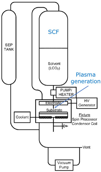
Figure 20.
A schematic diagram of an SCF chamber with a plasma generation setup (based on [139]).
7. Characterization Techniques
For a deep understanding of hybrid plasmas and their performances, a variety of characterization techniques are necessary. This chapter briefly lists important characterization techniques for plasma diagnostics as well as applications of hybrid plasmas.
Plasma diagnostic techniques include invasive methods like inserting probes in a plasma, passive spectroscopies such as OES [140], active spectroscopies such as LIF [66], Fourier transform infrared (FTIR) spectroscopy [141], mass spectroscopy [142], and electrical measurements. For a comprehensive review of plasma diagnostics, see [143,144].
For the applications of plasma processing, a broad range of material characterizations is needed. There are no limitations for the choice of characterization techniques. Characterization techniques include, but are not limited to: microscopic analysis, spectroscopic analysis, structural analysis (molecular structure, molecular weight, crystallinity, defects), elemental and compositional analysis, and measurement of chemical or physical (mechanical, thermal, electrical etc.) properties. Some of the fundamental characterization techniques are described in [145]. Major areas of the applications include characterization of gas, liquids, solid materials, and materials surfaces. Among them, surface characterization plays a unique and important role in relation to hybrid plasma processing, since in many applications, the essential changes after the plasma processing can be only at the surfaces or their vicinities. Commonly used surface characterization techniques include contact angle measurement for the estimation of surface tensions [146,147,148], FTIR spectroscopy, X-ray photoelectron spectroscopy (XPS), energy-dispersive X-ray spectrometry (EDS), Time of Flight secondary ionized mass spectrometer (TOF-SIMS) for surface chemistry analyses, atomic force microscopy (AFM), optical microscopy, and scanning electron microscopy (SEM) for morphological analyses [4]. Contact angle measurement is widely used in the industry. It is the simplest method for surface characterization, sensitively detecting the surface property with the analysis depth of approximately 1 nm or less.
8. Discussion
In this review, different types of hybrid plasmas have been explained and discussed. While the ambiguity of the term “hybrid plasmas” leads to a large variety of types of enhanced plasma, one must also consider whether a given “hybrid plasma” can suitably be called “hybrid” in terms of its configuration and effects; for example, one must contemplate whether a two-step process can appropriately be coined as a “hybrid” process. Additionally, while different configurations of plasmas may be interesting to discuss and file patents for, discussions must be had regarding what kinds of advantages these have in comparison to their nonhybrid counterparts. Without this, a hybrid–plasma configuration for the sake of discovering a new configuration may prove to be without much meaning.
How can research then move forward in this field of study? One idea worth mentioning is combining hybrid plasmas. Hill et al. [149] propose a gas reformer by a further hybridization process, comprised of an upstream gliding arc and downstream DBD in combination as shown in Figure 21. It is a combination of the concepts from Section 2.1 and Section 4.
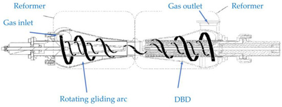
Figure 21.
A cross-sectional view of a gas reformer combining a gliding arc and a DBD (based on [149]).
In a similar yet slightly different way, Kusano et al. report a process to combine gliding arc and ultrasonic irradiation [109,150,151] as shown in Figure 22. The gliding arc is tilted, and ultrasound is irradiated vertically, relative to the specimen holder. The combination of gliding arc with ultrasonic irradiation further improves the treatment effect.
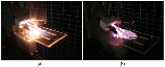
Figure 22.
Photo images of the gliding arc (a) without ultrasonic irradiation, and (b) with ultrasonic irradiation. Reproduced with permission from [109] Kusano et al., Surf. Eng.; published by Taylor & Francis, 2012.
It is also worth mentioning that even though the gliding arc itself is already a hybrid plasma, it takes the form of a single plasma, and therefore it can easily be subjected to further hybridization.
The assumption in studying hybrid plasmas is that treatments or processing by them are more beneficial compared to their nonhybrid counterparts. However, one must also discuss the disadvantages that accompany hybrid plasmas. For example, if the configuration of the hybrid plasma is relatively complicated, it can result in the need to produce expensive equipment. One must also consider the increase in the cost of manufacturing, maintenance, and investment for such a device. There are also environmental impacts to be considered, for the activation of hybrid plasmas may lead to the production of substances toxic to health or to the environment. Here, major environmental impacts of using plasma processing are reported to be due to the use of electricity for the generation and operation of the plasma [152]. It is therefore suggested that one be very selective in choosing which configurations of hybrid plasmas are industrially useful. Specifically, the advantages and disadvantages of each configuration must be weighed very carefully, especially when the effects of improvements by hybridization are not significant.
Taking an example in plasmas combined with ultrasonic irradiation, oftentimes this configuration on its own only yields moderate improvements [108,109,110,111]. However, under certain conditions, the improvements can be much more noticeable. It has been observed that even with under a 5-min exposure in helium DBD treatment at less than 1 W, the water contact angle decreases much more significantly with added ultrasonic irradiation than without, and this is especially visible for lower frequencies of ultrasound [61,107]. It has also been observed that if PET films are treated by DBD plasma without ultrasonic irradiation, it takes 30 times longer to reach the same level of plasma treatment effect compared to when ultrasonic irradiation is applied [104]. These results make a strong case for further pursuing this type of hybrid plasma.
Consider also that the application of hybrid plasma may also result in the obtainment of results that are simply unachievable by ordinary nonhybrid plasma, regardless of the energy and time used to operate it. These types of improvements are also very important to examine. For example, it is known that a DBD in air is an assembly of filamentary micro-discharges [153] and material surfaces that are exposed to it are inevitably unevenly treated. On the other hand, when the DBD–ultrasound configuration is operated in air at atmospheric pressure, polymer surfaces are treated uniformly [110]. It is foreseen that when air DBD is used and uniform treatment is required in bio or semiconductor applications, the ultrasound-assisted hybrid plasma processing can be worth consideration.
9. Summary and Outlook
Various types of hybrid plasmas are reviewed, referring to scientific literature and patents. They are briefly summarized below.
Plasmas driven by multiple electrical sources simultaneously (Section 2) are presented by combining two plasmas (Section 2.1), magnetron sputtering with RF or ECR plasma (Section 2.2), and plasma generated by superposing different frequencies or waveforms of voltages (Section 2.3). A noticeable uniqueness of the plasmas in Section 2.3 is that it is a single plasma, while those of Section 2.1 and Section 2.2 are a combination of a plurality of plasmas.
Plasmas driven by multiple different electrical sources sequentially (Section 3) are regarded as two-step processes rather than hybrid plasmas.
Plasmas having properties of thermal and nonthermal plasmas (Section 4) are represented by gliding arcs. They are also single plasmas but are generated without superposing excitation voltages.
Plasmas enhanced by additional energy (Section 5) are demonstrated by combining plasmas with thermal energy (Section 5.1), electron beam (Section 5.2), photoexcitation (Section 5.3), and acoustic energy or mechanical vibration (Section 5.4). The type of additional energy can be adequately selected in accordance with specific applications.
Plasmas operated in a unique medium (Section 6) are relatively new, and unique characteristics of reaction fields for chemical processes can be expected for the realization of novel materials processing.
Characterization techniques are listed in Section 7, and scopes of hybrid plasmas are discussed in Section 8.
There is no simple solution or criteria to select for the best choice of processes. However, appropriate selections must be made for the benefit of research and industry. The above examples will hopefully give the reader some insight into hybrid plasmas and encourage them to make further discoveries in this field of research.
Author Contributions
Conceptualization, Y.K.; investigation, R.K. and Y.K.; data curation, R.K.; writing—original draft preparation, R.K.; writing—review and editing, R.K. and Y.K.; visualization, R.K.; supervision, Y.K. All authors have read and agreed to the published version of the manuscript.
Funding
This research received no external funding.
Institutional Review Board Statement
Not applicable.
Informed Consent Statement
Not applicable.
Data Availability Statement
No new data were created or analyzed in this study. Data sharing is not applicable to this article.
Conflicts of Interest
The authors declare no conflict of interest.
References
- Fridman, A.; Kennedy, L.A. Plasma Physics and Engineering, 1st ed.; Taylor & Francis: New York, NY, USA, 2004. [Google Scholar] [CrossRef]
- Yoshida, T.; Tani, T.; Nishimura, H.; Akashi, K. Characterization of a hybrid plasma and its application to a chemical synthesis. J. Appl. Phys. 1983, 54, 640. [Google Scholar] [CrossRef]
- Kusano, Y. Plasma surface modification at atmospheric pressure. Surf. Eng. 2009, 25, 415–416. [Google Scholar] [CrossRef]
- Kusano, Y. Atmospheric pressure plasma processing for polymer adhesion—A review. J. Adhes. 2014, 90, 755–777. [Google Scholar] [CrossRef]
- McKelliget, J.W.; El-Kaddah, N. Modeling of materials synthesis in hybrid plasma reactors: Production of silicon by thermal decomposition of SiCI4. Metall. Trans. B 1990, 21, 589–598. [Google Scholar] [CrossRef]
- Saiki, G.; Kondo, J.; Takeda, K.; Mutsuo, M.; Tutomu, O. Process for Producing Ultrafine Particles of Metals, Metal Compounds and Ceramics and Apparatus Used Therefor. U.S. Patent 4,812,166 A, 14 March 1989. [Google Scholar]
- Cho, Y.K.; Tan, K.; Janakiraman, K.; Huang, J. Inductive/Capacitive Hybrid Plasma Source and System with Such Chamber. U.S. Patent 9,034,143 B2, 19 May 2015. [Google Scholar]
- Chen, X.; Garg, S.; Yang, J.G. RPS Assisted RF Plasma Source for Semiconductor Processing. U.S. Patent 9,741,545 B2, 22 August 2017. [Google Scholar]
- Chen, X.; Garg, S.; Yang, J.G. RPS Assisted RF Plasma Source for Semiconductor Processing. U.S. Patent 10,056,233 B2, 21 August 2018. [Google Scholar]
- Cui, Z.; Zhang, H.; Wang, A.; Chen, Z.; Ingle, N.K. 3D NAND High Aspect Ratio Structure Etch. U.S. Patent 10,692,880 B2, 23 June 2020. [Google Scholar]
- Roppel, T.A.; Asmussen, J.; Reinhard, D.K. Dual Plasma Microwave Apparatus and Method for Treating a Surface. U.S. Patent 4,691,662 A, 8 September 1987. [Google Scholar]
- Tonmitr, N.; Yonesu, A.; Hayashi, N. Surface sterilization using LF-microwave hybrid plasma. Jpn. J. Appl. Phys. 2021, 60, SAAE01. [Google Scholar] [CrossRef]
- Bárdoš, L.; Baránková, H. Device for Hybrid Plasma Processing. U.S. Patent 6,899,054 B1, 31 May 2005. [Google Scholar]
- Bárdoš, L.; Baránková, H.; Gustavsson, L.E.; Teer, D.G. New microwave and hollow cathode hybrid plasma sources. Surf. Coat. Technol. 2004, 177–178, 651–656. [Google Scholar] [CrossRef]
- Choi, D.K. Hybrid Plasma Reactor. U.S. Patent 8,866,390 B2, 21 October 2014. [Google Scholar]
- Choi, D.K. Hybrid Plasma Reactor. U.S. Patent 9,451,686 B2, 20 September 2016. [Google Scholar]
- Vaduganathan, L.; Poonamallie, B.A.; Nagalingam, M. Effects of Temperature and Flow Rates of Ozone Generator on the DBD by Varying Various Electrical Parameters. Am. J. Appl. Sci. 2012, 9, 1496–1502. [Google Scholar] [CrossRef][Green Version]
- Kusano, Y.; Evetts, J.E.; Hutchings, I.M. Deposition of boron carbon nitride films by dual cathode magnetron sputtering. Thin Solid Films 1999, 343–344, 250–253. [Google Scholar] [CrossRef]
- Aijaz, A.; Lundin, D.; Larsson, P.; Helmersson, U. Dual-magnetron open field sputtering system for sideways deposition of thin films. Surf. Coat. Technol. 2010, 204, 2165–2169. [Google Scholar] [CrossRef]
- Kong, P.C.; Grandy, J.D. Methods of Chemically Converting First Materials to Second Materials Utilizing Hybrid-Plasma Systems. U.S. Patent 6,372,156 B1, 16 April 2002. [Google Scholar]
- Kong, P.C. Modular Hybrid Plasma Gasifier for Use in Converting Combustible Material to Synthesis Gas. U.S. Patent 10,208,263 B2, 19 February 2019. [Google Scholar]
- Smith, D.L. Thin-Film Deposition: Principles and Practice, 1st ed.; McGraw Hill, Inc.: New York, NY, USA, 1995; pp. 1–616. [Google Scholar]
- Chen, G.S.; Yang, L.C.; Tian, H.S.; Hsu, C.S. Evaluating substrate bias on the phase-forming behavior of tungsten thin films deposited by diode and ionized magnetron sputtering. Thin Solid Films 2005, 484, 83–89. [Google Scholar] [CrossRef]
- Chiu, K.F.; Barber, Z. Texture development in silver films deposited by ionised magnetron sputter deposition. Thin Solid Films 2000, 358, 264–269. [Google Scholar] [CrossRef]
- Chiu, K.P.; Barber, Z.H.; Somekh, R.E. The control of film stress using ionised magnetron sputter deposition. Thin Solid Films 1999, 343–344, 39–42. [Google Scholar] [CrossRef]
- Tranchant, J.; Angleraud, B.; Yessier, P.Y.; Besland, M.P.; Landesman, J.P.; Djouadi, M.A. Residual stress control in MoCr thin films deposited by ionized magnetron sputtering. Surf. Coat. Technol. 2006, 200, 6549–6553. [Google Scholar] [CrossRef]
- Tranchant, J.; Tessier, P.Y.; Landesman, J.P.; Djouadi, M.A.; Angleraud, B.; Renault, P.O.; Girault, B.; Goudeau, P. Relation between residual stresses and microstructure in Mo(Cr) thin films elaborated by ionized magnetron sputtering. Surf. Coat. Technol. 2008, 202, 2247–2251. [Google Scholar] [CrossRef]
- Christou, C.; Chiu, K.F.; Barber, Z.H. A spectroscopic study of DC magnetron and RF coil plasmas in ionised physical vapour deposition. Vacuum 2000, 58, 250–255. [Google Scholar] [CrossRef]
- Schneider, J.M.; Sproul, W.D. Crystalline alumina deposited at low temperatures by ionized magnetron sputtering. J. Vac. Sci. Technol. A 1997, 15, 1084–1088. [Google Scholar] [CrossRef]
- Schneider, J.M.; Sproul, W.D.; Matthews, A. Reactive ionized magnetron sputtering of crystalline alumina coatings. Surf. Coat. Technol. 1998, 98, 1473–1476. [Google Scholar] [CrossRef]
- Kusano, Y.; Christou, C.; Barber, Z.H.; Evetts, J.E.; Hutchings, I.M. Deposition of carbon nitride films by ionised magnetron sputtering. Thin Solid Films 1999, 355–356, 117–121. [Google Scholar] [CrossRef]
- Kusano, Y.; Barber, Z.H.; Evetts, J.E.; Hutchings, I.M. Tribological and mechanical properties of carbon nitride films deposited by ionised magnetron sputtering. Surf. Coat. Technol. 2000, 124, 104–109. [Google Scholar] [CrossRef]
- Kusano, Y.; Barber, Z.H.; Evetts, J.E.; Hutchings, I.M. Influence of inert gases on ionized magnetron plasma deposition of carbon nitride thin films. Surf. Coat. Technol. 2003, 174–175, 601–605. [Google Scholar] [CrossRef]
- Angleraud, B.; Mubumbila, N.; Tessier, P.Y. Effect of a r.f. antenna on carbon nitride films deposited by ionized r.f. magnetron sputtering. Diam. Relat. Mater. 2003, 12, 1093–1097. [Google Scholar] [CrossRef]
- Angleraud, B.; Tessier, P.Y. Improved film deposition of carbon and carbon nitride materials on patterned substrates by ionized magnetron sputtering. Surf. Coat. Technol. 2004, 180–181, 59–65. [Google Scholar] [CrossRef]
- Yoshida, T. Low-gas-pressure sputtering by means of microwave-enhanced magnetron plasma excited by electron cyclotron resonance. Appl. Phys. Lett. 1992, 61, 1733. [Google Scholar] [CrossRef]
- Xu, J.; Xinlu Deng, X.L.; Zhang, J.L.; Lu, W.G.; Ma, T.C. Characterization of CNx films prepared by twinned ECR plasma source enhanced DC magnetron sputtering. Thin Solid Films 2001, 390, 107–112. [Google Scholar] [CrossRef]
- Chatterjee, P.K.; Malhi, S.D.S.; deWit, M.; Hosack, H.; Harward, M.G.; Moslehi, M.M. Integrated Circuits. In Reference Data for Engineers: Radio, Electronics, Computer, and Communications, 9th ed.; Middleton, W.M., Valkenburg, M.E.V., Eds.; Newnes: Woburn, MA, USA, 2002; pp. 20-1–20-113. [Google Scholar] [CrossRef]
- Efthimion, P.C.; Gilson, E.; Grisham, L.; Kolchin, P.; Davidson, R.C.; YU, S.; Logan, B.G. ECR plasma source for heavy ion beam charge neutralization. Laser Part. Beams 2003, 21, 37–40. [Google Scholar] [CrossRef][Green Version]
- Gudmundsson, J.T. Ionized physical vapor deposition (IPVD): Magnetron sputtering discharges. J. Phys. Conf. Ser. 2008, 100, 082002. [Google Scholar] [CrossRef]
- Helmersson, U.; Lattemann, M.; Bohlmark, J.; Ehiasarian, A.P.; Gudmundsson, J.T. Ionized physical vapor deposition (IPVD): A review of technology and applications. Thin Solid Films 2006, 513, 1–24. [Google Scholar] [CrossRef]
- Sarakinos, K.; Alami, J.; Konstantinidis, S. High power pulsed magnetron sputtering: A review on scientific and engineering state of the art. Surf. Coat. Technol. 2010, 204, 1661–1684. [Google Scholar] [CrossRef]
- Ito, W.; Oishi, A.; Okayama, S.; Yoshida, Y.; Homma, N.; Morishita, T.; Haga, T.; Yamaya, K. Highest crystallinity of a-axis YBCO films by DC-94.92 MHz hybrid plasma magnetron sputtering. Phys. C Supercond. 1993, 204, 295–298. [Google Scholar] [CrossRef]
- Yoshida, Y.; Ito, W.; Morishita, T. Method of Manufacturing Y-Ba-Cu-O Superconducting Thin Film. U.S. Patent 5,466,665 A, 14 November 1995. [Google Scholar]
- Ahn, H.S.; Hayashi, N.; Ihara, S.; Yamabe, C. Ozone Generation Characteristics by Superimposed Discharge in Oxygen-Fed Ozonizer. Jpn. J. Appl. Phys. 2003, 42, 6578–6583. [Google Scholar] [CrossRef]
- Leipold, F.; Schultz-Jensen, N.; Kusano, Y.; Bindslev, H.; Jacobsen, T. Decontamination of objects in a sealed container by means of atmospheric pressure plasmas. Food Control 2011, 22, 1296–1301. [Google Scholar] [CrossRef]
- Alim, M.M.; Oudini, N.; Tadjine, R. Experimental investigation of hybrid plasma reactor for duplex surface treatment. Eur. Phys. J. Appl. Phys. 2022, 97, 15. [Google Scholar] [CrossRef]
- Díaz-Guillén, J.C.; Alvarez-Vera, M.; Díaz-Guillén, J.A.; Acevedo-Davila, J.L.; Naeem, M.; Hdz-García, H.M.; Granda-Gutiérrez, E.E.; Muños-Arroyo, R. A Hybrid Plasma Treatment of H13 Tool Steel by Combining Plasma Nitriding and Post-Oxidation. J. Mater. Eng. Perform. 2018, 27, 6118–6126. [Google Scholar] [CrossRef]
- Díaz-Guillén, J.C.; Naeem, M.; Hdz-García, H.M.; Acevedo-Davila, J.L.; Díaz-Guillén, M.R.; Khan, M.A.; Iqbal, J.; Mtz-Enriquez, A.I. Duplex plasma treatment of AISI D2 tool steel by combining plasma nitriding (with and without white layer) and post-oxidation. Surf. Coat. Technol. 2020, 385, 125420. [Google Scholar] [CrossRef]
- Ueda, M.; Gomes, G.F.; Kostov, K.G.; Reuther, H.; Lepienski, C.M.; Soares, P.C., Jr.; Takai, O.; Silva, M.M. Results from Experiments on Hybrid Plasma Immersion Ion Implantation/Nitriding Processing of Materials. Braz. J. Phys. 2004, 34, 1632–1637. [Google Scholar] [CrossRef]
- Throwarh, K.; Hauert, R.; Thorwarth, G. Coating for a Titanium Alloy Substrate. EU Patent 2,996,732 B1, 1 January 2020. [Google Scholar]
- Hsieh, C.C.; Lin, D.L.; Tseng, C.P.; Tsai, W.F.; Chen, J.S.; Ai, C.F. Roll-to-Roll Hybrid Plasma Modular Coating System. U.S. Patent 9,892,889 B2, 13 February 2018. [Google Scholar]
- Fridman, A.; Nester, S.; Kennedy, L.A.; Saveliev, A.; Mutaf-Yardimci, O. Gliding arc gas discharge. Prog. Energy Combust. Sci. 1999, 25, 211–231. [Google Scholar] [CrossRef]
- Zhu, J.J.; Gao, J.L.; Ehn, A.; Aldén, M.; Li, Z.S.; Moseev, D.; Kusano, Y.; Salewski, M.; Alpers, A.; Gritzmann, P.; et al. Measurements of 3D slip velocities and plasma column lengths of a gliding arc discharge. Appl. Phys. Lett. 2015, 106, 044101. [Google Scholar] [CrossRef]
- Du, C.M.; Wang, J.; Zhang, L.; Li, H.X.; Liu, H.; Xiong, Y. The application of a non-thermal plasma generated by gas–liquid gliding arc discharge in sterilization. New J. Phys. 2012, 14, 013010. [Google Scholar] [CrossRef]
- Kusano, Y.; Sørensen, B.F.; Andersen, T.L.; Toftegaard, H.L.; Leipold, F.; Salewski, M.; Sun, Z.W.; Zhu, J.J.; Li, Z.S.; Aldén, M. Water-cooled non-thermal gliding arc for adhesion improvement of glass-fibre-reinforced polyester. J. Phys. D Appl. Phys. 2013, 46, 135203. [Google Scholar] [CrossRef]
- Kusano, Y.; Teodoru, S.; Leipold, F.; Andersen, T.L.; Sørensen, B.F.; Rozlosnik, N.; Michelsen, P.K. Gliding arc discharge—Application for adhesion improvement of fibre reinforced polyester composites. Surf. Coat. Technol. 2008, 202, 5579–5582. [Google Scholar] [CrossRef]
- Kusano, Y.; Sørensen, B.F.; Andersen, T.L.; Leipold, F. Adhesion improvement of glass-fibre reinforced polyester composites by gliding arc discharge treatment. J. Adhes. 2013, 89, 433–459. [Google Scholar] [CrossRef]
- Kusano, Y.; Bardenshtein, A.; Morgen, P. Fluoropolymer coated alanine films treated by atmospheric pressure plasmas—In comparison with gamma irradiation. Plasma Process. Polym. 2018, 15, 1700131. [Google Scholar] [CrossRef]
- Kusano, Y.; Berglund, L.; Aitomäki, Y.; Oksman, K.; Madsen, B. Gliding arc surface modification of carrot nanofibre coating—Perspective for composite processing. IOP Conf. Ser. Mater. Sci. Eng. 2016, 139, 012027. [Google Scholar] [CrossRef]
- Kusano, Y.; Andersen, T.L.; Toftegaard, H.L.; Leipold, F.; Bardenshtein, A.; Krebs, N. Plasma treatment of carbon fibres and glass-fibre-reinforced polyesters at atmospheric pressure for adhesion improvement. Int. J. Mater. Eng. Innov. 2014, 5, 122–137. [Google Scholar] [CrossRef]
- Kusano, Y.; Salewski, M.; Leipold, F.; Zhu, J.J.; Ehn, A.; Li, Z.S.; Aldén, M. Stability of alternating current gliding arcs. Eur. Phys. J. D 2014, 68, 319. [Google Scholar] [CrossRef]
- Lu, S.Y.; Sun, X.M.; Li, X.D.; Yan, J.H.; Du, C.M. Physical characteristics of gliding arc discharge plasma generated in a laval nozzle. Phys. Plasmas 2012, 19, 072122. [Google Scholar] [CrossRef]
- Mitsugi, F.; Furukawa, J.; Ohshima, T.; Kawasaki, H.; Kawasaki, T.; Aoqui, S.; Stryczewska, H.D. Observation of dynamic behavior of gliding arc discharge. Eur. Phys. J. Appl. Phys. 2013, 61, 24308. [Google Scholar] [CrossRef]
- Mutaf-Yardimci, O.; Saveliev, A.V.; Porshnev, P.I.; Fridman, A.A.; Kennedy, L.A. Non-equilibrium effects in gliding arc discharges. Ann. N. Y. Acad. Sci. 1999, 891, 304–308. [Google Scholar] [CrossRef]
- Šperka, J.; Souček, P.; Van Loon, J.J.W.A.; Dowson, A.; Schwarz, C.; Krause, J.; Kroesen, G.; Kudrle, V. Hypergravity effects on glide arc plasma. Eur. Phys. J. D 2013, 67, 1–9. [Google Scholar] [CrossRef]
- Sun, Z.W.; Zhu, J.J.; Li, Z.S.; Aldén, M.; Leipold, F.; Salewski, M.; Kusano, Y. Optical diagnostics of a gliding arc. Opt. Express 2013, 21, 6028–6044. [Google Scholar] [CrossRef]
- Tu, X.; Gallon, H.J.; Whitehead, J.C. Dynamic behavior of an atmospheric argon gliding arc plasma. IEEE Trans. Plasma Sci. 2011, 39, 2900–2901. [Google Scholar] [CrossRef]
- Zhao, T.L.; Liu, J.L.; Li, X.S.; Liu, J.B.; Song, Y.H.; Xu, Y.; Zhu, A.M. Temporal evolution characteristics of an annular-mode gliding arc discharge in a vortex flow. Phys. Plasmas 2014, 21, 053507. [Google Scholar] [CrossRef]
- Zhu, J.J.; Gao, J.L.; Li, Z.S.; Ehn, A.; Aldén, M.; Larsson, A.; Kusano, Y. Sustained diffusive alternating current gliding arc discharge in atmospheric pressure air. Appl. Phys. Lett. 2014, 105, 234102. [Google Scholar] [CrossRef]
- Zhu, J.J.; Sun, Z.W.; Li, Z.S.; Ehn, A.; Aldén, M.; Salewski, M.; Leipold, F.; Kusano, Y. Dynamics, OH distributions and UV emission of a gliding arc at various flow-rates investigated by optical measurements. J. Phys. D Appl. Phys. 2014, 47, 295303. [Google Scholar] [CrossRef]
- Zhu, J.J.; Gao, J.L.; Ehn, A.; Aldén, M.; Larsson, A.; Kusano, Y.; Li, Z.S. Spatiotemporally resolved characteristics of a gliding arc discharge in a turbulent air flow at atmospheric pressure. Phys. Plasmas 2017, 24, 013514. [Google Scholar] [CrossRef]
- Gangoli, S.P.; Gutsol, A.F.; Fridman, A.A. A non-equilibrium plasma source: Magnetically stabilized gliding arc discharge: I. Design and diagnostics. Plasma Sources Sci. Technol. 2010, 19, 065003. [Google Scholar] [CrossRef]
- Sagás, J.C.; Neto, A.H.; Filho, A.C.P.; Maciel, H.S.; Lacava, P.T. Basic characteristics of gliding-arc discharges in air and natural gas. IEEE Trans. Plasma Sci. 2011, 39, 775–780. [Google Scholar] [CrossRef]
- Xu, G.; Ding, X. Electrical characterization of a reverse vortex gliding arc reactor in atmosphere. IEEE Trans. Plasma Sci. 2012, 40, 3458–3464. [Google Scholar] [CrossRef]
- Kuznetsova, I.V.; Kalashnikov, N.Y.; Gutsol, A.F.; Fridman, A.A.; Kennedy, L.A. Effect of “overshooting” in the transitional regimes of the low-current gliding arc discharge. J. Appl. Phys. 2002, 92, 4231–4237. [Google Scholar] [CrossRef]
- Yu, L.; Yan, J.H.; Tu, X.; Li, X.D.; Lu, S.Y.; Cen, K.F. Effect of water on gliding arc discharge fluctuation. Europhys. Lett. 2008, 83, 45001. [Google Scholar] [CrossRef]
- Zhang, C.; Shao, T.; Xu, J.; Ma, H.; Duan, L.; Ren, C.; Yan, P. A gliding discharge in open air sustained by high-voltage resonant ac power supply. IEEE Trans. Plasma Sci. 2012, 40, 2843–2849. [Google Scholar] [CrossRef]
- Zhang, C.; Shao, T.; Yan, P.; Zhou, Y. Nanosecond-pulse gliding discharges between point-to-point electrodes in open air. Plasma Sources Sci. Technol. 2014, 23, 035004. [Google Scholar] [CrossRef]
- Korolev, Y.D.; Frants, O.B.; Geyman, V.G.; Landl, N.V.; Kasyanov, V.S. Low-current ‘gliding arc’ in air flow. IEEE Trans. Plasma Sci. 2011, 39, 3319–3325. [Google Scholar] [CrossRef]
- Benstaali, B.; Boubert, P.; Cheron, B.G.; Addou, A.; Brisset, J.L. Density and Rotational Temperature Measurements of the OH° and NO° Radicals Produced by a Gliding Arc in Humid Air. Plasma Chem. Plasma Process. 2002, 22, 553–571. [Google Scholar] [CrossRef]
- Chernyak, V.Y.; Prysiazhnevych, I.V.; Solomenko, O.V.; Olzewski, S.V.; Diatczyk, J.; Stryczewska, H.; Belenok, N.; Shyht, I. Determining of the electronic excitation temperature in atmospheric pressure plasmas by using emission spectra of metals with complex low-resolved multiplet structure. Ukr. J. Phys. 2010, 55, 1083–1089. [Google Scholar]
- Li, H.; Xie, M. Plasma parameters of a gliding arc jet at atmospheric pressure obtained by a line-ratio method. Plasma Sci. Technol. 2013, 15, 776. [Google Scholar] [CrossRef]
- Tu, X.; Yu, L.; Yan, J.H.; Cen, K.F.; Chéron, B.G. Dynamic and spectroscopic characteristics of atmospheric gliding arc in gas-liquid two-phase flow. Phys. Plasmas 2009, 16, 113506. [Google Scholar] [CrossRef]
- Zhu, J.J.; Ehn, A.; Gao, J.L.; Kong, C.D.; Aldén, M.; Larsson, A.; Salewski, M.; Leipold, F.; Kusano, Y.; Li, Z.S. Translational, rotational, vibrational and electron temperatures of a gliding arc discharge. Opt. Express 2017, 25, 20243–20257. [Google Scholar] [CrossRef]
- Dalaine, V.; Cormier, J.M.; Lefaucheux, P. A gliding discharge applied to H2S destruction. J. Appl. Phys. 1998, 83, 2435. [Google Scholar] [CrossRef]
- Dalaine, V.; Cormier, J.M.; Pellerin, S.; Lefaucheux, P. H2S destruction in 50 Hz and 25 kHz gliding arc reactors. J. Appl. Phys. 1998, 84, 1215. [Google Scholar] [CrossRef]
- Dalaine, V.; Cormier, J.M.; Pellerin, S.; Hnatiuc, E. Study and modelling of a 50 Hz gliding discharge. In Proceedings of the 6th International Conference on Optimization of Electrical and Electronic Equipments (OPTIM ’98), Brasov, Romania, 14–15 May 1998. [Google Scholar] [CrossRef]
- Richard, F.; Cormier, J.M.; Pellerin, S.; Chapelle, J. Physical study of a gliding arc discharge. J. Appl. Phys. 1996, 79, 2245. [Google Scholar] [CrossRef]
- Pellerin, S.; Richard, F.; Chapelle, J.; Cormier, J.M.; Musiol, K. Heat string model of bi-dimensional dc Glidarc. J. Phys. D Appl. Phys. 2000, 33, 2407–2419. [Google Scholar] [CrossRef]
- Pellerin, S.; Cormier, J.M.; Richard, F.; Musiol, K.; Chapelle, J. Determination of the electrical parameters of a bi-dimensional d.c. Glidarc. J. Phys. D Appl. Phys. 1999, 32, 891–897. [Google Scholar] [CrossRef]
- Fridman, A.; Gutsol, A.; Gangoli, S.; Ju, Y.; Ombrello, Y. Characteristics of Gliding Arc and Its Application in Combustion Enhancement. J. Propuls. Power 2008, 24, 1216–1228. [Google Scholar] [CrossRef]
- Ombrello, T.; Qin, X.; Ju, Y.; Gutsol, A.; Fridman, A.; Carter, C. Combustion Enhancement via Stabilized Piecewise Nonequilibrium Gliding Arc Plasma Discharge. AIAA J. 2006, 44, 142–150. [Google Scholar] [CrossRef]
- Skowrónska, B.; Chmielewski, T.; Golański, D.; Szulc, J. Weldability of S700MC steel welded with the hybrid plasma + MAG method. Manuf. Rev. 2020, 7, 4. [Google Scholar] [CrossRef]
- Korzhik, V.N.; Pashchin, N.A.; Mikhoduj, O.L.; Grinyuk, A.A.; Babich, A.A.; Khaskin, V.Y. Comparative evaluation of methods of arc and hybrid plasma-arc welding of aluminum alloy 1561 using consumable electrode. Paton Weld. J. 2017, 4, 30–34. [Google Scholar] [CrossRef]
- Chen, Q.; Wang, G.; Zhang, H.; Runsheng, L. Research on microstructure and mechanical properties of hybrid plasma arc and micro-rolling additive manufacturing of Inconel 718 superalloy. Rapid Prototyp. J. 2022, 28, 1509–1519. [Google Scholar] [CrossRef]
- Asai, S.; Ogawa, T.; Ishizaki, Y.; Minemura, T.; Minami, H.; Iyazaki, S.M. Application of Plasma MIG Hybrid Welding to Dissimilar Joints between Copper and Steel. Weld. World 2012, 56, 37–42. [Google Scholar] [CrossRef]
- Liu, R.; Hao, Y.; Wang, T.; Wang, L.; Bogaerts, A.; Guo, H.; Yi, Y. Hybrid plasma-thermal system for methane conversion to ethylene and hydrogen. Chem. Eng. J. 2023, 463, 142442. [Google Scholar] [CrossRef]
- Vasilieva, T.M.; Vasiliev, M.N.; Garaeva, V.V.; Zlobin, I.S.; Mint, Z.Y.; Htau, K.M.; Kyaw, H.W.Y.K.; Zaw, H.K.K. Hybrid plasma—Prospects for application in medicine and biology. Russ. Phys. J. 2020, 62, 2092–2100. [Google Scholar] [CrossRef]
- Chen, Z.; Ventzek, P.; Ranjan, A. Hybrid Electron Beam and RF Plasma System for Controlled Content of Radicals and Ions. U.S. Patent 11,205,562 B2, 21 December 2021. [Google Scholar]
- Kurz, T.; Heinemann, T.; Gilljohann, M.F.; Chang, Y.Y.; Couperus Cabadağ, J.P.; Debus, A.; Kononenko, O.; Pausch, R.; Schöbel, S.; Assmann, R.R.; et al. Demonstration of a compact plasma accelerator powered by laser-accelerated electron beams. Nat. Commun. 2021, 12, 2895. [Google Scholar] [CrossRef]
- Varghese, B.; Verhagen, R.; Jurna, M.; Palero, J.A.; Horton, M.R.; Bonito, V. Skin Treatment Device for Multiphoton Ionization-Based Skin Treatment. U.S. Patent 10,092,771 B2, 9 October 2018. [Google Scholar]
- Bayer, E.; Hoeschele, J.; Steinwandel, J.; Willneff, R. Laser-Plasma Hybrid Welding Method. U.S. Patent 6,940,036 B2, 6 September 2005. [Google Scholar]
- Fang, C.; Kusano, Y.; Bardenshtein, A. High-speed plasma treatment of polyethylene terephthalate films using ultrasound assisted dielectric barrier discharge. Packag. Technol. Sci. 2021, 35, 643–649. [Google Scholar] [CrossRef]
- Kusano, Y.; Madsen, B.; Berglund, L.; Aitomäki, Y.; Oksman, K. Dielectric barrier discharge plasma treatment of cellulose nanofibre surfaces. Surf. Eng. 2018, 34, 825–831. [Google Scholar] [CrossRef]
- Kusano, Y.; Madsen, B.; Berglund, L.; Oksman, K. Modification of cellulose nanofiber surfaces by He/NH3 plasma at atmospheric pressure. Cellulose 2019, 26, 7185–7194. [Google Scholar] [CrossRef]
- Kusano, Y.; Norrman, K.; Singh, S.V.; Leipold, F.; Morgen, P.; Bardenshtein, A.; Krebs, N. Ultrasound enhanced 50 Hz plasma treatment of glass-fiber-reinforced polyester at atmospheric pressure. J. Adhes. Sci. Technol. 2013, 27, 825–833. [Google Scholar] [CrossRef]
- Kusano, Y.; Singh, S.V.; Bardenshtein, A.; Krebs, N.; Rozlosnik, N. Plasma surface modification of glass fibre reinforced polyester enhanced by ultrasonic irradiation. J. Adhes. Sci. Technol. 2010, 24, 1831–1839. [Google Scholar] [CrossRef]
- Kusano, Y.; Singh, S.V.; Norrman, K.; Drews, J.; Leipold, F.; Rozlosnik, N.; Bardenshtein, A.; Krebs, N. Ultrasound enhanced plasma surface modification at atmospheric pressure. Surf. Eng. 2012, 28, 453–457. [Google Scholar] [CrossRef]
- Kusano, Y.; Singh, S.V.; Norrman, K.; Leipold, F.; Drews, J.; Morgen, P.; Bardenshtein, A.; Krebs, N. Ultrasound enhanced plasma treatment of glass-fibre-reinforced polyester in atmospheric pressure air for adhesion improvement. J. Adhes. 2011, 87, 720–731. [Google Scholar] [CrossRef]
- Kusano, Y.; Cederløf, D.J.H.; Fæster, S. Plasma surface modification of glass fibre sizing for manufacturing polymer composites. Key Eng. Mater. 2020, 843, 159–164. [Google Scholar] [CrossRef]
- Krebs, N.; Bardenshtein, A.; Kusano, Y.; Bindslev, H.; Mortensen, H.J. Enhancing Plasma Surface Modification Using High Intensity and High Power Ultrasonic Acoustic Waves. U.S. Patent 8,399,795 B2, 19 March 2013. [Google Scholar]
- Otsuka, T.; Teranishi, K.; Nakane, T. Effect of Ultrasound in High-Pressure Glow Discharge. Jpn. J. Appl. Phys. 2001, 40, 3797–3800. [Google Scholar] [CrossRef]
- Nakane, T.; Miyajima, T.; Otsuka, T. Current Waveforms of Electric Discharge in Air under High-Intensity Acoustic Standing. Jpn. J. Appl. Phys. 2004, 43, 2852–2856. [Google Scholar] [CrossRef]
- Bálek, R.; Pekárek, S.; Bartáková, Z. Power ultrasound interaction with DC atmospheric pressure electrical discharge. Ultrasonics 2006, 44, e549–e553. [Google Scholar] [CrossRef]
- Zhang, Q.H.; Du, R.; Zhang, J.H.; Zhang, Q.B. An investigation of ultrasonic-assisted electrical discharge machining in gas. Int. J. Mach. Tools Manuf. 2006, 46, 1582–1588. [Google Scholar] [CrossRef]
- Khatri, B.C.; Rathod, P.; Valaki, J.B. Ultrasonic vibration–assisted electric discharge machining: A research review. Proc. Inst. Mech. Eng. B J. Mech. Eng. Manuf. 2015, 230, 319–330. [Google Scholar] [CrossRef]
- Hatsuzawa, T.; Hayase, M.; Oguchi, T. Mechanical vibration assisted plasma etching for etch rate and anisotropy improvement. Precis. Eng. 2002, 26, 442–447. [Google Scholar] [CrossRef]
- Bálek, R.; Pekárek, S.; Bartáková, Z. Ultrasonic resonator with electrical discharge cell for ozone generation. Ultrasonics 2007, 46, 227–234. [Google Scholar] [CrossRef]
- Pekárek, S.; Bálek, R. Ozone generation by hollow-needle to plate electrical discharge in an ultrasound field. J. Phys. D Appl. Phys. 2004, 37, 1214. [Google Scholar] [CrossRef]
- Drews, J.; Kusano, Y.; Leipold, F.; Bardenshtein, A.; Krebs, N. Ozone production in a dielectric barrier discharge with ultrasonic irradiation. Ozone Sci. Eng. 2011, 33, 483–488. [Google Scholar] [CrossRef]
- Kusano, Y.; Drews, J.; Leipold, F.; Fateev, A.; Bardenshtein, A.; Krebs, N. Influence of ultrasonic irradiation on ozone generation in a dielectric barrier discharge. J. Phys. Conf. Ser. 2012, 406, 012006. [Google Scholar] [CrossRef]
- Pekárek, S.; Bálek, R.; Kuhn, J.; Pospíšil, M. Effect of ultrasound waves on a hollow needle to plate electrical discharge in air or mixture of air with VOCs. Czechoslov. J. Phys. 2006, 56, B982–B989. [Google Scholar] [CrossRef]
- Choi, K.S.; Nakamura, S.; Murata, Y. Improvement of Charging Performance of Corona Charger in Electrophotography by Irradiating Ultrasonic Wave to Surrounding Region of Corona Electrode. Jpn. J. Appl. Phys. 2005, 44, 3248–3252. [Google Scholar] [CrossRef]
- Li, J.; Ma, C.; Zhu, S.; Yu, F.; Dai, B.; Yang, D. A Review of Recent Advances of Dielectric Barrier Discharge Plasma in Catalysis. Nanomaterials 2019, 9, 1428. [Google Scholar] [CrossRef]
- Bogaerts, A.; Tu, X.; Whitehead, J.C.; Centi, G.; Lefferts, L.; Guaitella, O.; Azzolina-Jury, F.; Kim, H.H.; Murphy, A.B.; Schneider, W.F.; et al. The 2020 plasma catalysis roadmap. J. Phys. D Appl. Phys. 2020, 53, 443001. [Google Scholar] [CrossRef]
- Khoja, A.H.; Tahir, M.; Amin, N.A.S. Recent developments in non-thermal catalytic DBD plasma reactor for dry reforming of methane. Energy Convers. Manag. 2019, 183, 529–560. [Google Scholar] [CrossRef]
- García-Moncada, N.; van Rooij, G.; Cents, T.; Lefferts, L. Catalyst-assisted DBD plasma for coupling of methane: Minimizing carbon-deposits by structured reactors. Catal. Today 2021, 369, 210–220. [Google Scholar] [CrossRef]
- Bruggeman, P.J.; Bogaerts, A.; Pouvesle, J.M.; Robert, E.; Szili, E.J. Plasma-liquid interactions. J. Appl. Phys. 2021, 130, 200401. [Google Scholar] [CrossRef]
- Chung, K.H.; Lam, S.S.; Park, Y.K.; Kim, S.J.; Jung, S.C. Application of liquid-phase plasma for the production of hydrogen and carbon from the plasma-induced cracking of liquid hydrocarbons. Fuel 2022, 328, 125297. [Google Scholar] [CrossRef]
- Joshi, A.A.; Locke, B.R.; Arce, P.; Finney, W.C. Formation of hydroxyl radicals, hydrogen peroxide and aqueous electrons by pulsed streamer corona discharge in aqueous solution. J. Hazard. Mater. 1995, 41, 3–30. [Google Scholar] [CrossRef]
- Locke, B.R.; Sato, M.; Sunka, P.; Hoffmann, M.R.; Chang, J.S. Electrohydraulic Discharge and Nonthermal Plasma for Water Treatment. Ind. Eng. Chem. Res. 2006, 45, 882–905. [Google Scholar] [CrossRef]
- Goto, M.; Sasaki, M.; Kiyan, T.; Fang, T.; Roy, B.C.; Namihira, T.; Akiyama, H.; Hara, M. Reaction in Plasma Generated in Supercritical Carbon Dioxide. J. Phys. Conf. Ser. 2008, 121, 082009. [Google Scholar] [CrossRef]
- Stauss, S.; Muneoka, H.; Terashima, K. Review on plasmas in extraordinary media: Plasmas in cryogenic conditions and plasmas in supercritical fluids. Plasma Sources Sci. Technol. 2018, 27, 023003. [Google Scholar] [CrossRef]
- Kawashima, A.; Nomura, S.; Toyota, H.; Takemori, T.; Mukasa, S.; Maehara, T. A supercritical carbon diaoxide plasma process for preparing tungsten oxide nanowire. Nanotechnology 2007, 18, 495603. [Google Scholar] [CrossRef] [PubMed]
- Kiyan, T.; Uemura, A.; Tanaka, K.; Zhang, C.H.; Namihira, T.; Sakugawa, T.; Katsuki, S.; Akiyama, H.; Roy, B.C.; Sasaki, M.; et al. Pulsed discharge plasmas in supercritical carbon dioxide. In Proceedings of the IEEE Pulsed Power Conference, Monterey, CA, USA, 13–17 June 2005. [Google Scholar] [CrossRef]
- Kawashima, A.; Toyota, H.; Nomura, S.; Takemori, T.; Mukasa, S.; Maehara, T.; Yamashita, H. 27.12 MHz plasma generation in supercritical carbon dioxide. J. Appl. Phys. 2007, 101, 093303. [Google Scholar] [CrossRef]
- Kawashima, A.; Nomura, S.; Toyota, H. Carbon-Coated Metal Element-Containing Nanowire Manufacturing Method. JP Patent 4,958,085 B2, 20 June 2012. [Google Scholar]
- Jackson, D.P. Method and Apparatus for Treating a Substrate with Dense Fluid and Plasma. U.S. Patent 8,197,603 B2, 12 June 2012. [Google Scholar]
- Crintea, D.L.; Czarnetzki, U.; Iordanova, S.; Koleva, I.; Luggenhölscher, D. Plasma diagnostics by optical emission spectroscopy on argon and comparison with Thomson scattering. J. Phys. D Appl. Phys. 2009, 42, 045208. [Google Scholar] [CrossRef]
- Hest, M.F.A.v.; Graaf, A.d.; Sanden, M.C.M.v.d.; Hest, M.F.A.v.; Graaf, A.d.; Schram, D.C. Use of in situ FTIR spectroscopy and mass spectrometry in an expanding hydrocarbon plasma. Plasma Sources Sci. Technol. 2000, 9, 615. [Google Scholar] [CrossRef]
- Rowe, B. A mass spectrometer for plasma diagnostics. Measurements of ion translational temperature, polarization and velocity effects. Int. J. Mass Spectrom. Ion Phys. 1975, 16, 209–223. [Google Scholar] [CrossRef]
- Auciello, O.; Flamm, D.L. Plasma Diagnostics, Discharge Parameters and Chemistry, 1st ed.; Academic Press: Cambridge, MA, USA, 1989; pp. 1–470. [Google Scholar] [CrossRef]
- Ishikawa, K. Chapter 5—Plasma diagnostics. In Cold Plasma in Food and Agriculture: Fundamentals and Applications, 1st ed.; Misra, N.N., Schlüter, O., Cullen, P.J., Eds.; Academic Press: Cambridge, MA, USA, 2016; pp. 117–141. [Google Scholar] [CrossRef]
- Leng, Y. Materials Characterization: Introduction to Microscopic and Spectroscopic Methods, 2nd ed.; Wiley-VCH: Weinheim, Germany, 2013; pp. 1–383. [Google Scholar] [CrossRef]
- Drelich, J.W.; Boinovich, L.; Chibowski, E.; Volpe, C.D.; Hołysz, L.; Marmur, A.; Siboni, S. Contact Angles: History of over 200 Years of Open Questions. Surf. Innov. 2020, 8, 3–27. [Google Scholar] [CrossRef]
- Kusano, R.; Boulton, G.; Kusano, Y. Saltwater—Wettability on polymer surfaces and determination of surface tension. Int. J. Surf. Sci. Eng. 2021, 15, 281–293. [Google Scholar] [CrossRef]
- Kusano, R.; Kusano, Y. Symmetric expressions of surface tension components. J. Adhes. 2023. published online. [Google Scholar] [CrossRef]
- Hill, G. Modular Plasma Reformer Treatment System. U.S. Patent 10,293,303 B2, 21 May 2019. [Google Scholar]
- Kusano, Y.; Norrman, K.; Drews, J.; Leipold, F.; Singh, S.V.; Morgen, P.; Bardenshtein, A.; Krebs, N. Gliding arc surface treatment of glass fiber reinforced polyester enhanced by ultrasonic irradiation. Surf. Coat. Technol. 2011, 205, S490–S494. [Google Scholar] [CrossRef]
- Kusano, Y.; Zhu, J.J.; Ehn, A.; Li, Z.S.; Aldén, M.; Salewski, M.; Leipold, F.; Bardenshtein, A.; Krebs, N. Observation of gliding arc surface treatment. Surf. Eng. 2015, 31, 282–288. [Google Scholar] [CrossRef]
- King, B.; Patel, D.; Chen, J.Z.; Drapanauskaite, D.; Handler, R.; Nozaki, T.; Baltrusaitis, J. Comprehensive process and environmental impact analysis of integrated DBD plasma steam methane reforming. Fuel 2021, 304, 121328. [Google Scholar] [CrossRef]
- Kogelschatz, U. Dielectric-barrier Discharges: Their History, Discharge Physics, and Industrial Applications. Plasma Chem. Plasma Process. 2003, 23, 1–46. [Google Scholar] [CrossRef]


Disclaimer/Publisher’s Note: The statements, opinions and data contained in all publications are solely those of the individual author(s) and contributor(s) and not of MDPI and/or the editor(s). MDPI and/or the editor(s) disclaim responsibility for any injury to people or property resulting from any ideas, methods, instructions or products referred to in the content. |
© 2023 by the authors. Licensee MDPI, Basel, Switzerland. This article is an open access article distributed under the terms and conditions of the Creative Commons Attribution (CC BY) license (https://creativecommons.org/licenses/by/4.0/).