Article

Optimization of Components with Topology Optimization for Direct Additive Manufacturing by DLMS

Faculty of Mechanical Engineering, University of West Bohemia, 301 00 Plzen, Czech Republic
*
Author to whom correspondence should be addressed.
Materials 2023, 16(15), 5422; https://doi.org/10.3390/ma16155422
Submission received: 20 June 2023 / Revised: 30 July 2023 / Accepted: 31 July 2023 / Published: 2 August 2023
(This article belongs to the Special Issue Developments in Additive Manufacturing and 3D Printing)

Abstract

:
This paper presents a novel design methodology that validates and utilizes the results of topology optimization as the final product shape. The proposed methodology aims to streamline the design process by eliminating the need for remodeling and minimizing printing errors through process simulation. It also eliminates the repeated export and import of data between software tools. The study includes a case study involving the steering column housing of a racing car, where Siemens NX Topology Optimization was used for optimization, and verification analysis was conducted using the NX Nastran solver. The final solution was fabricated using AlSi10Mg via direct metal laser sintering on a 3D printer and successfully validated under real conditions. In conclusion, this paper introduces a comprehensive design methodology for the direct utilization of topology optimization, which was validated through a case study, yielding positive results.

1. Introduction

Topology optimization is advantageous for manufacturers, as it determines the optimal material distribution in a design space based on required loads. Nowadays, topology optimization extends its applications to simulations in other technical fields, such as an article of Mr. Cao, who used a topology optimization for a next-generation wireless data center network [1]. However, a significant drawback is the need to remodel the structure for the final design. Structural optimization is a relatively old research field. Analytical and numerical techniques have long been exploited in the solution of structural design problems. In the 17th century, in his book Discorsi e dimostrazioni matematiche, Galileo Galilei introduced one of the first concepts about the optimal shape of structural elements [2]. His book was followed by several works by Gottfried W. Leibniz, who formulated the basis of analytic procedure. Maxwell’s works in 1870 introduced a theory to find the best material distribution through a principal stress field for civil engineering problems (bridges, etc.). In 1904, Anthony G. M. Michell continued Maxwell’s work to create optimal beam structures [3]. The use of structural optimization based on numerical techniques has seen significant growth with the coming of modern computing devices and materials [4]. Many types of structural optimization exist today, and they are directly implemented in commercial software [5]. Geometry (sizing) optimization [6], topometric optimization, topography optimization [7], shape optimization [8,9], freeform optimization, and topology optimization [10] are among the most well known.
The origins of topological optimization can be traced back to the early 1970s, when Prager and Rozvarny formulated their initial theory [11]. This optimization technique aims to determine the optimal distribution of structure within a predefined area. It employs a fixed number of finite elements and assigns a single input variable, known as the pseudo-density modulus, to each element of the resolved volume fraction. Topological optimization methods can generally be classified into three main categories: element-based, discrete, and combined approaches [10,12,13,14].
Solid isotropic microstructures with penalization (SIMP) [15,16], rational approximation of material properties (RAMP) [17], optimal microstructure with penalization (OMP) [18], non-optimal microstructures (NOM), and dual discrete programming (DDP) [19] are among the most used element-based methods of topology optimization. Evolutionary structural optimization (ESO) [20], bidirectional evolutionary structural optimization (BESO) [21], and additive evolutionary structural optimization (AESO) [22] are some of the most famous discrete methods of topology optimization. Extended finite-element method (XFEM) together with deformable simplicial complex (DSC) is a combined approach for solving topology optimization.
Additive manufacturing technology, also referred to as 3D printing, has been in existence for several decades. However, in recent years, it has sparked a manufacturing revolution. This process involves the joining of materials to create objects based on 3D model data, typically layer by layer [23]. Initially, additive manufacturing was primarily used for producing visual prototypes, test samples, and educational purposes [24]. However, over time, it has evolved into an advanced technique capable of manufacturing end-user products [25] across various industries [26,27], including aviation, motorsports, trains, medicine, and more [28]. The widespread adoption of additive manufacturing has revolutionized manufacturing processes, enabling the production of complex and customized products with significant implications for various sectors.
In response to the significant growth and widespread adoption of additive manufacturing technology in recent years, the International Organization for Standardization (ISO) and the American Society for Testing and Materials (ASTM) have developed multiple standards. These standards encompass general principles, terminology [29,30], and specific guidelines for design [31,32]. These efforts aim to establish a unified framework and ensure consistency in the application of additive manufacturing across various industries.
The ISO/ASTM 52900-15 standard [33] is considered a foundational document in the field of additive manufacturing. It offers a fundamental framework for classifying additive manufacturing technologies, specifically by dividing them into seven main categories based on the additive manufacturing process: (VAT, SLA, DLP, and CDLP) photopolymerization [34,35], material extrusion [36,37], material jetting [38,39], binder jetting [40,41], powder bed fusion [42,43,44,45], directed energy deposition [46,47], and sheet lamination [48].
In this case, the powder bed fusion–additive manufacturing (AM) process, specifically direct metal laser sintering (DMLS), was utilized. This process was pioneered by EOS (Electro Optical System, Krailling, Germany) in 1994, becoming the first commercially viable method for producing metal parts through AM. The underlying principle of this technology involves the selective melting of thin layers (20–60 µm) of metal powder using a laser or electron beam. The build platform is used to construct parts layer by layer, with a relatively high level of geometric precision (±0.05 mm). The metal powder is deposited onto the build platform either through a re-coater arm or a roller from the powder supply. L-PBF additive technology is suitable for producing prototypes and one-off production, as demonstrated by Rokicki and Rahmati in their papers [49,50]. Indeed, L-PBF can be utilized for fabricating structures with lattice structures. Gupta, in his work, mentioned the damping effects of this structure, which can be advantageous, for example, for dampening vibrations transmitted into the steering wheel of a student formula car. This can improve the overall performance and handling of the vehicle [51].
It is common practice that the resulting geometry from topology optimization needs to be remodeled before verification and printing. Prathyusha and Budu applied a methodology that involved topology optimization for a landing door bracket. However, during the process, it was necessary to perform remodeling after the initial topology optimization [52,53]. Similarly, Dienemann employed topological optimization for battery-pack cooling for forced convection based on Darcy flow. However, the efficiency of its design was also compromised due to the need for remodeling the outcome of topological optimization [54]. Barbieri contrasted design methodologies by utilizing generative design and topology optimization tools. Although the generative design yielded printable outcomes, his approach overlooked manufacturability evaluation and the potential errors that may arise during the manufacturing process [55]. The objective of this research is to establish a fundamental methodology for the direct utilization of topology optimization outcomes in additive manufacturing, specifically laser powder bed fusion (L-PBF). The proposed methodology aims to address the challenges associated with preserving the integrity of the optimized structure during the additive manufacturing process while also compensating for errors and limitations inherent in the AM process, such as self-supporting structures and distortion compensation. This research seeks to integrate various aspects that are typically addressed separately in the existing literature, including the influence of support placement and deformation induced by thermal loading [56]. Kim investigated the influence of the placement, type, and size of supports on part deformation in his article. This research served as a basis for simulating support placement and was extended to incorporate compensatory deformations into the CAD model, aiming to achieve a more accurately manufactured component [56]. In his article, Bouabbou assessed the influence of residual powder around the printed part on heat transfer and the occurrence of printing errors. The simulation of the manufacturing process presented in this study takes into consideration the thermal properties of the residual powder for heat transfer analysis [57]. By combining these activities into a unified workflow, the proposed methodology aims to enhance the overall efficiency and effectiveness of the topology optimization and additive manufacturing process. The housing of the steering column of a racing car was used as the case study for determining the basic methodology of the “rapid prototyping” process.

Current Solution of Case Study

The current solution of the steering column housing is a CNC-machined part made from aluminum alloy (EN AW 7075). This part is connected to the frame of the car using a steel (SR355) weldment holder. The layout of the housing with all connected components (internal axes, gears, bearings, etc.) is shown in Figure 1. The weight of the current solution of the steering column housing and the holder is 0.514 kg.

2. Optimization of the Steering Column Housing

2.1. Material

In spite of progress in the case of developing metal composite materials [58], EOS aluminum AlSi10Mg [59,60] (Light Metal for Motorsports and Aerospace Interior Applications, provided by the EOS GmbH Electro Optical Systems in the form of a gas-atomized metal powder) was set as the material of the structure. This alloy provides a favorable price-to-performance ratio, rendering it a cost-effective selection, and it is widely used for motorsports and aerospace applications [56,61]. The chemical composition of the material is given in Table 1.
The experimental measurements of the material AlSi10Mg were taken for determination of the mechanical properties. Specimen geometry and the testing method for tensile test were chosen according to the ASTM E8/E8M-16a standard [62]. The specimens were fabricated on the print bed in two main positions: horizontally and vertically to the print bed, using the EOS M 290 machine [63,64]. The process parameters used for fabrication of the AlSi10Mg specimens are given in Table 2.
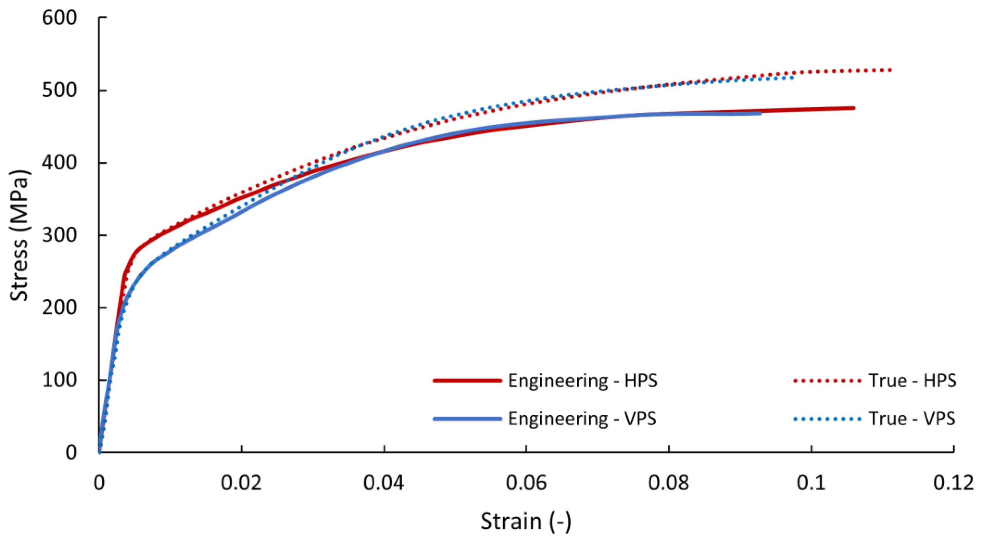
A Zwick-Roell Z050 electro-mechanical testing machine with a 5 kN load cell and 20 Hz sampling frequency was used for uniaxial tensile tests. The stress–strain curves of the vertically and horizontally printed specimens are given in Figure 2.
The mechanical properties of the material are summarized in Table 3.

2.2. Design Area of Optimization

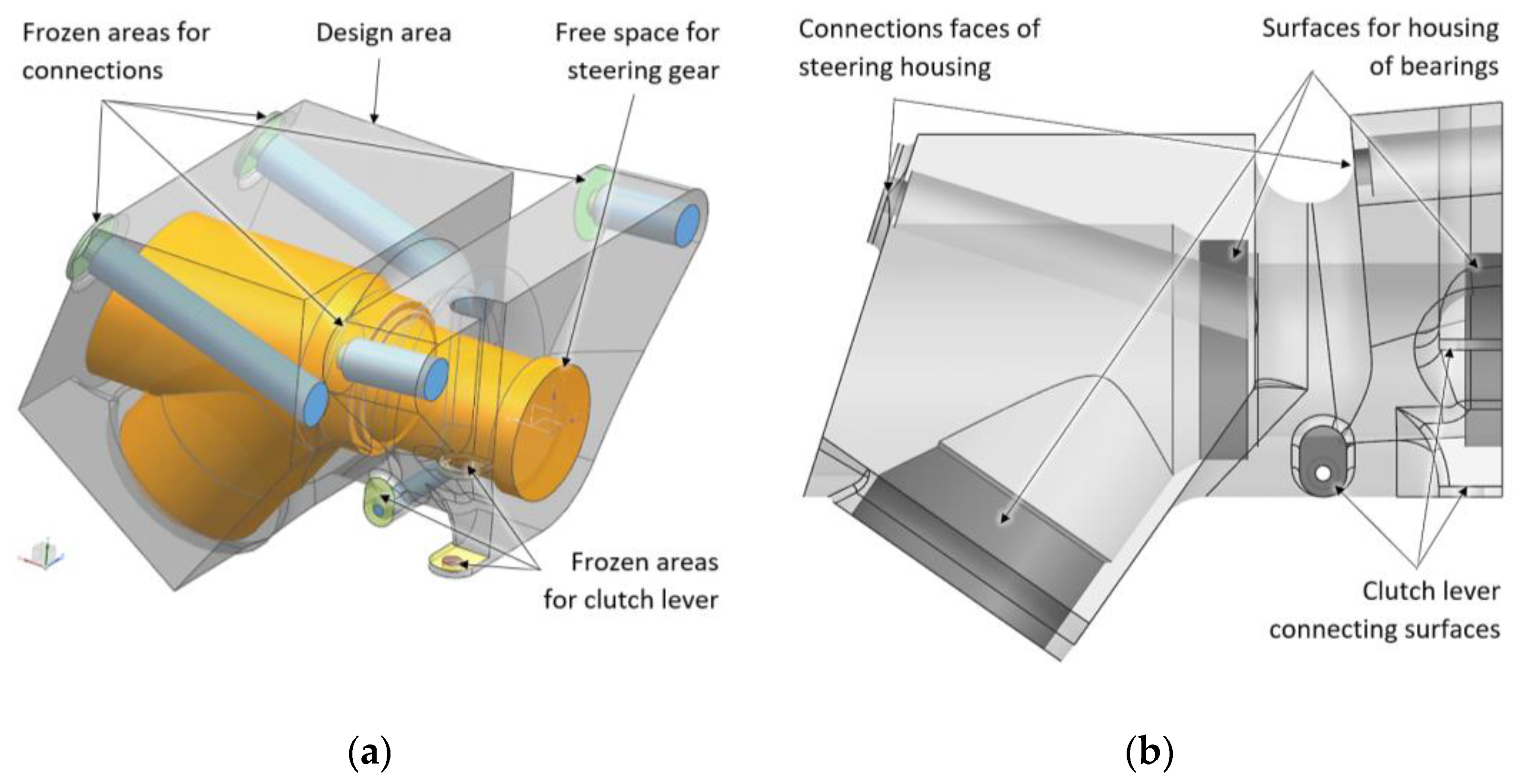
The Siemens NX1888 Topology Optimization for Designers software (Siemens NX 12.0.2) was used for optimization. The volume that represents the mounting boundaries where the final structure may be was created. The space for connecting the related components, bolts for attaching the steering column housing to the frame, and the necessary space for the tools were subtracted from this volume. The final model of the design area for topology optimization is given in Figure 3.

2.3. Parameters of Topology Optimization

The minimization of the strain energy subject to the mass target (minimalizing compliance) of the structure was chosen as the objective function of the optimization. The mass target of the final structure, Cm = 0.29 kg, was set as the design constraint. A 2.5 mm input mesh resolution was used for the optimization. Material spreading of 70% and self-supporting with an angle to the base plate of 45% were used as manufacturing constraints. Frozen areas (areas where optimization cannot remove material) were created with the definition of the minimum thickness of the walls (2.5 mm for surfaces that are intended for connecting the steering column housing and 3 mm for cylindrical faces that are intended for housing the bearings of the main shafts of the steering gear) (see Figure 3).

2.4. Specification of Input Load Cases

Obtaining the loading condition directly from real measurements is the optimal approach [65]. Together, the four most critical load cases were used for structural analysis as the input for topology optimization (according to critical driving conditions). The first load case was cornering (radial forces in transverse direction: FRtI = 2153 N for the cylindrical face of the housing of the first shaft bearing; FRtII = −4819 N for the second housing of the bearing; and moment MtIII = 132 Nm). The second load case was deceleration (axial force FAd = −1890 N). The third one was acceleration (axial force FAa = −1610 N) and their combination (cornering with deceleration). The individual load cases were calculated analytically using data from the data logger of the telemetry from a real race (G-G diagram).
The final solution with a mass of 0.288 kg was found after 49 optimization cycles. Automatic smoothing of the results of the optimized structure (so-called normalized material) is a great advantage of this optimization solver (by the associated postprocessor). The results of the final structure are given in Figure 4.

3. Verification Analysis of the Result of TO

3.1. Generation of FE Mesh from STL Model

The final structure obtained from the topology optimization is in the stereolithography file format (STL). An STL format describes the surface of a structure or a solid object using the unit normal and vertices of unstructured triangles. This format approximates the 3D surfaces of a solid model with oriented triangles (facets) of different sizes and shapes (aspect ratio) in order to achieve a sufficiently fine resolution to achieve the required quality and tolerance of the surface of the structure [66]. This format is otherwise directly applicable to 3D printing, but it is difficult to perform on STL discretization using the finite-element method for verification analysis. Using an STL directly to create a volumetric 3D FEM mesh is supported by only a few FEM pre-processors and has many limitations—such as the possibility of using only the first-order elements, etc. A polygon model created by remodeling an STL structure by using conventional CAD methods is the most common way, but it is very time-consuming.
One of the new methods is the so-called convergent model that eliminates the necessity for remodeling. Convergent-type solid or sheet bodies are the faceted representation of geometry in which edges and faces are based on tessellation rather than on parameterization. Convergent-type CAD geometry is typically generated automatically by special modeling features of reverse-engineering modules. A closed surface of the STL body without mesh errors is the only condition for creating a convergent model.
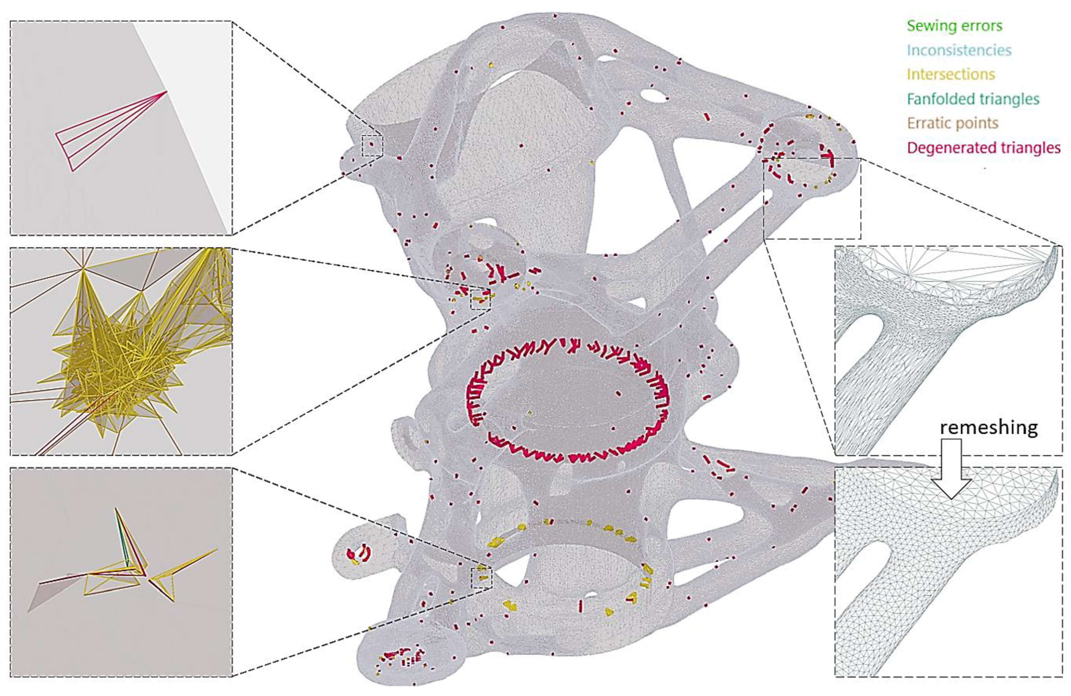
Intersections, degenerated triangles, erratic points, inconsistencies, fanfolded triangles, isolated points, and edges are the most common mesh errors. Intersections mean that one or more triangles penetrate another one. Degenerated triangles are triangles of the STL surface that are too small (their ratio of height × length is less than 1 × 20). Erratic points are, for example, if two holes touch each other. Inconsistencies exist if triangles of the STL surface having opposite surface normals border on each other. Fanfolded triangles of the surface partly lie on top of each other and are connected to each other on at least one side. Isolated points and edges are features that do not belong to any triangle of the mesh and are located separately. All mesh errors of the STL were corrected using GOM Inspect 2016 software. Overall, 5092 mesh errors were detected and repaired using the Eliminate Mesh Errors function (see Figure 5).

3.2. Verification Using Independent Structural Analysis

The final structure obtained from the topology optimization and repaired in GOM Inspect 2016 software was imported into the CAD module of the Siemens NX 1888 software, and it was translated to a convergence (polygon) model to allow the application of the FEM mesh. Siemens NX Simcenter 3D 1888 software was used as the pre-processor of the FEM analysis [67]. The 3D FEM mesh with tetrahedral second-order elements with the relative size of the edge 3 mm was applied on the convergence body (see Figure 6).
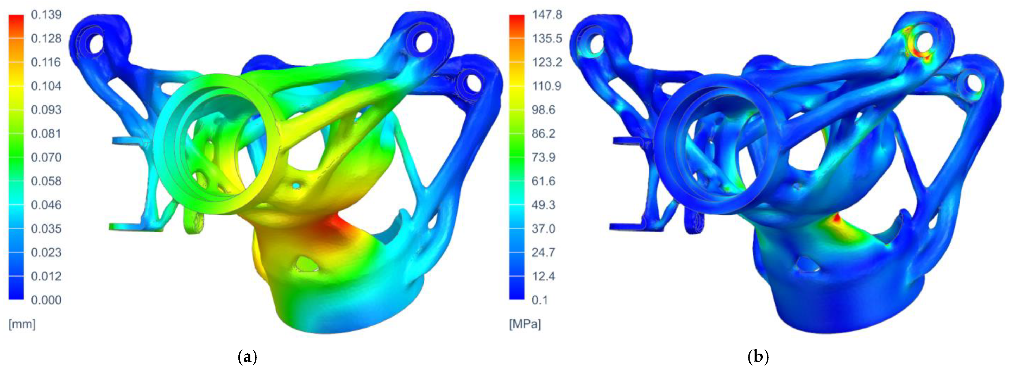
The boundary conditions were taken from the optimization analysis, and the NX Nastran—SOL 106 Static Nonlinear Solver was used. The mechanical properties of the material were defined according to the parameters obtained by experimental measurements given in Figure 2 and Table 3. The results of the displacement and equivalent stress (according to Von Mises) for the most critical load case (the combination of deceleration and cornering) are given in Figure 7. The displacement results showed sufficient stiffness of the overall structure, and the values of the reduced stress did not exceed the required safety of the structure, i.e., k = 1.25.

4. Functional Specimen

4.1. Pre-Processing of Functional Specimen Manufacturability

The manufacturability of the final structure using L-PBF was analyzed prior to the fabrication process in the AM module of Siemens NX 1888 software. The analysis included checks for the printable volume to ensure the model was within the acceptable range for AM. Additionally, the minimum radii of concave and convex curvature (with a specific radius value of rc = 0.5 mm), overhangs [68], and minimum wall thickness were assessed. Maintaining an appropriate wall thickness (recommended value of tw = 0.4 mm) is crucial to prevent distortion caused by the high temperatures involved in the process.
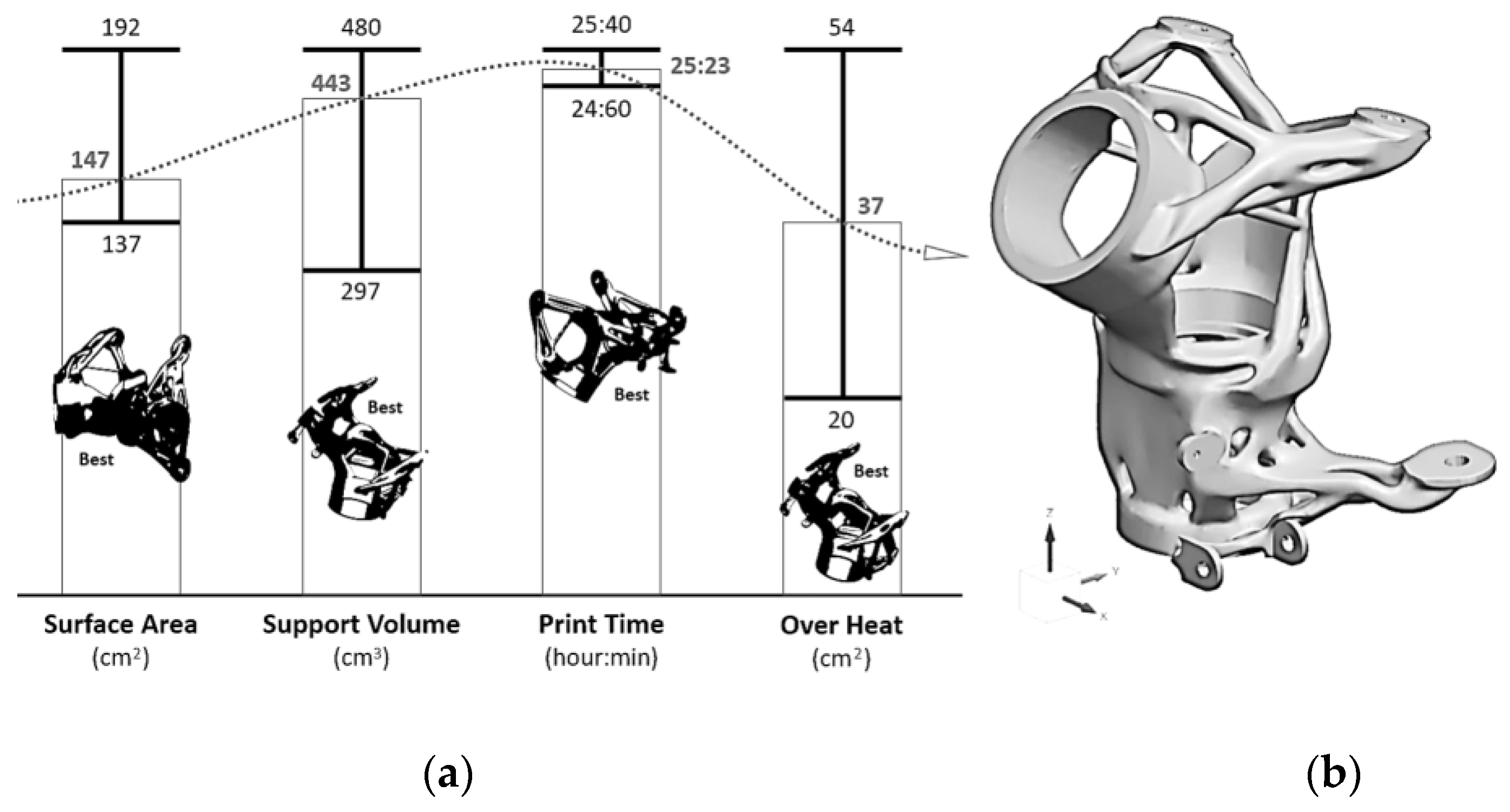
The orientation of the part relative to the printing bed is a crucial parameter (lines 65–66). The part orientation was optimized using Siemens NX 1888 Additive Manufacturing software. The four main parameters in the optimization process (surface area, print time, support volume [69,70,71], and overheating) were considered. The weighting method was used in the optimization process. In this case, overheating and surface area were selected as priority parameters. The final part orientation was found to have a surface area of 187 cm2 (i.e., 40% of the total), overheating of 33 cm2 (i.e., 7% of the total), and support volume of 336 cm3. (The area needing support was 74.1 cm2, i.e., 16% of the total.) The most favorable orientation for individual parameters, including the ranges of individual values, and the final results are given at Figure 8.
The orientation of the part with generated block supports (with critical angle 45° and gap between part and bed 8 mm) is given in Figure 9.

4.2. Numerical Simulation of Printing Process

The L-PBF printing process generates high temperatures, which can result in various issues such as local overheating, geometric distortion, shrink lines, and even printing interruptions caused by collisions between the re-coater and the fabricated part. To address these challenges, numerical simulation of the additive manufacturing process proves valuable, as it enables the prediction of potential issues and provides opportunities for compensation or complete elimination of these problems. By leveraging numerical simulation, it becomes possible to proactively mitigate the impact of residual heat and optimize the printing process for enhanced quality and performance.
In this case, the Simcenter™ 3D 1888 Additive Manufacturing software was employed. This specialized module utilizes a digital twin of the printed part, encompassing the build tray, residual powder, and support structures, to simulate the direct metal laser sintering process. The software employs a finite-element method-based solver, providing a significantly higher precision representation of the simulated part compared to conventional solvers that employ coarse voxel meshes.
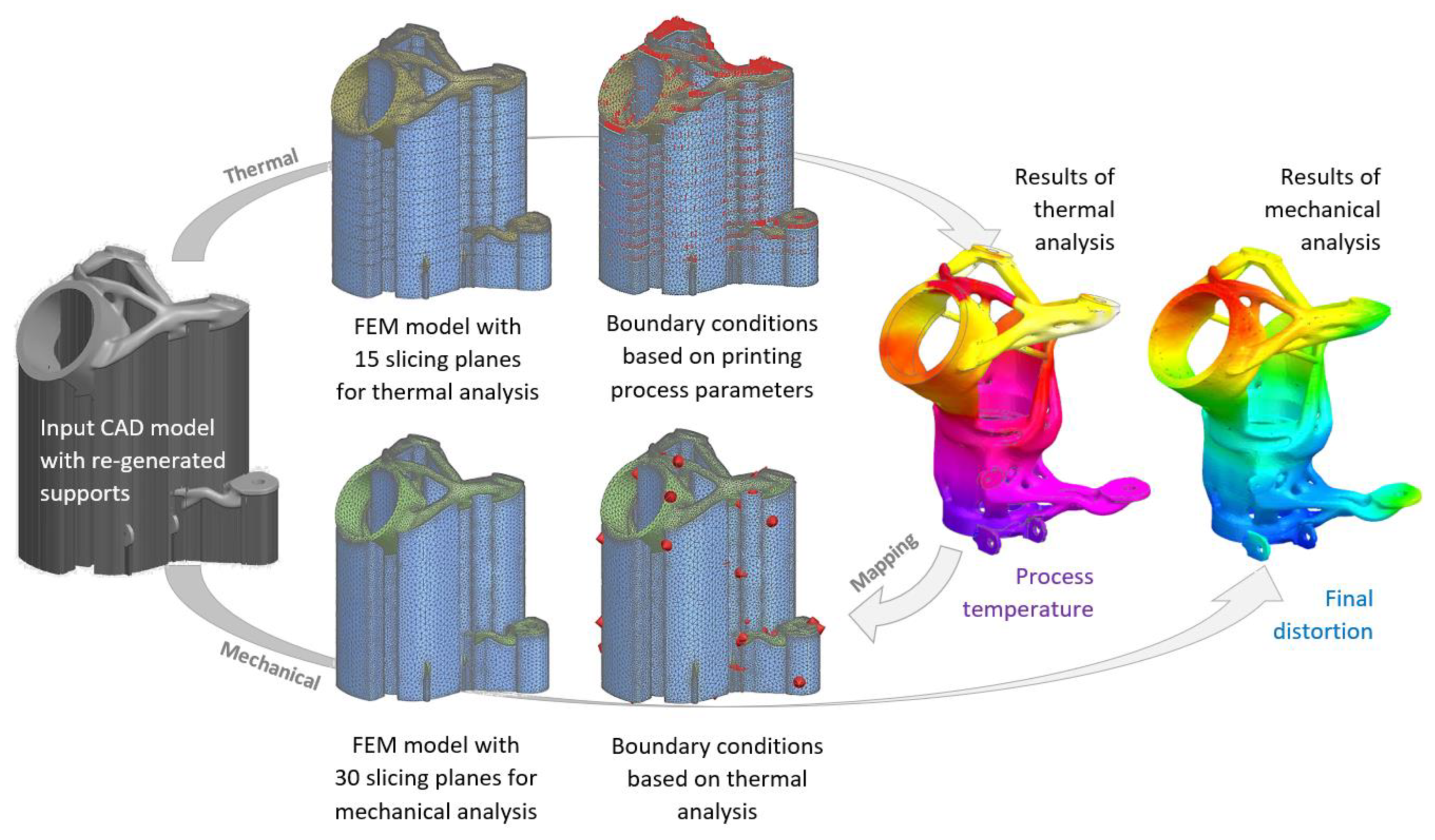
In the first stage, the block supports were re-generated to simulation supports with homogenized orthotropic mechanical properties. The simulation in this process consists of two interconnected analyses (thermal computed with Simcenter Samcef Thermal—Heat transfer solver and mechanical computed with Simcenter Samcef—Nonlinear Analysis solver). The finite-element models (FEM) were created for both simulations, including the printing powder and slicing of printed parts.
The thermal FEM was created from first-order tetrahedral CTETRA4 elements with a relative element size of 1.8 mm (950,582 elements) and 15 slicing planes for boundary conditions. The mechanical FEM was created from the same CTETRA4 elements with a relative element size of 1.5 mm (1,043,392 elements) and 30 slicing planes for boundary conditions. The thermal and mechanical FEM models used are shown in Figure 10.
The boundary conditions (heat loads, radiation, and convection) in the thermal simulation were automatically generated for individual slicing planes by the pre-processor based on the defined process parameters for printing (recoating time, base plate and ambient temperature, heat transfer coefficient of the ambient gas, alpha of the build plate, laser power, etc.). The mainly used process/thermal parameters are given in Table 4. The same process parameters as for the production of test specimens (see Table 2) were used for numerical simulation.
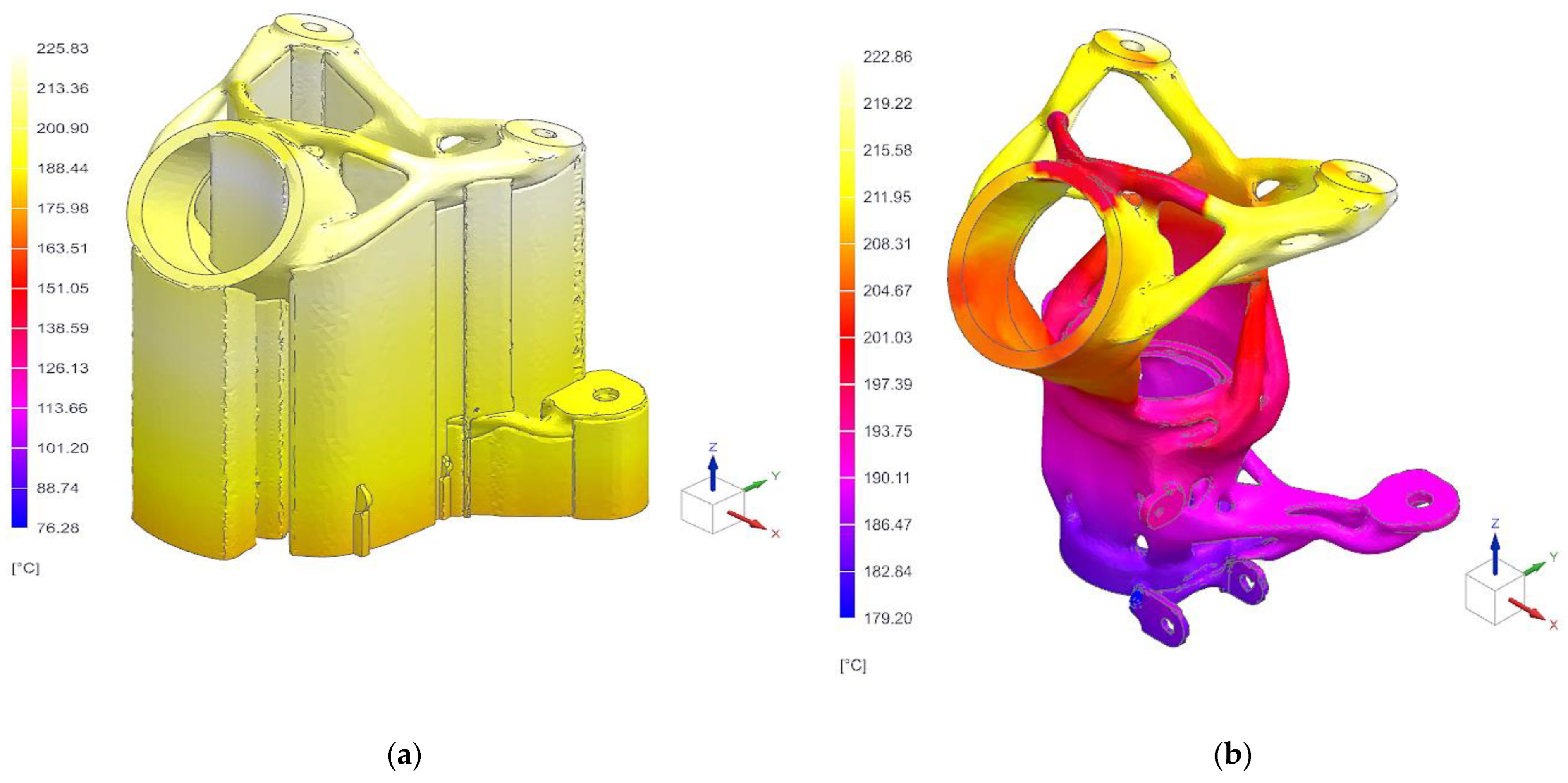
The final printing temperature for the part containing the supports was found in the range of 76.3 °C to 225.8 °C, and for the print holder printout itself, the temperature ranged from 179.2 °C to 222.9 °C. The results of the final interpolated temperatures of the printing process of the part and supports are given in Figure 11.
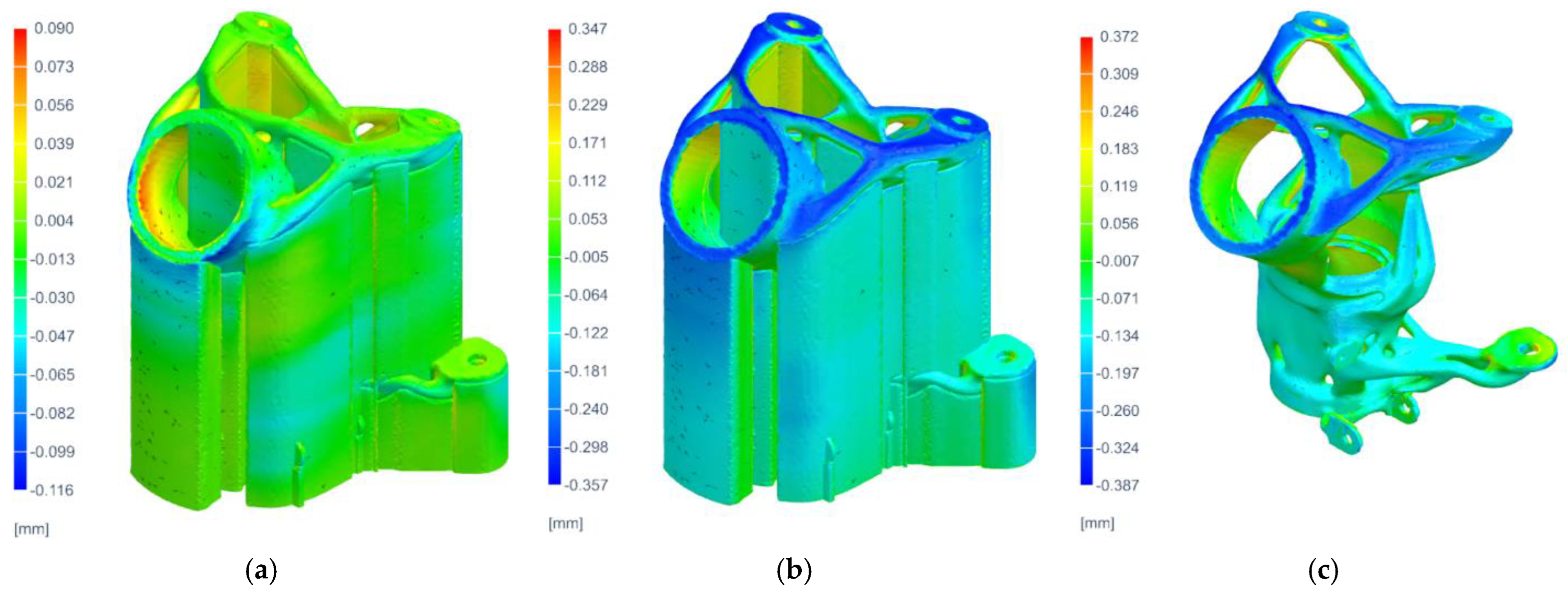
In the next step, the results from the thermal simulation were mapped into mechanical simulation, and the distortion analyses (during printing, after cool down, and after removing supports) were computed. The results of the displacements of the part distortion sequence (after printing, after cool down, and after support removal) are the main outputs of the mechanical analysis.
The maximum displacement was logically achieved for the results of the parts after the removal of the supports and reached 0.387 mm (ABS) in the upper area of the print. The graphical results of the part distortion are given in Figure 12.
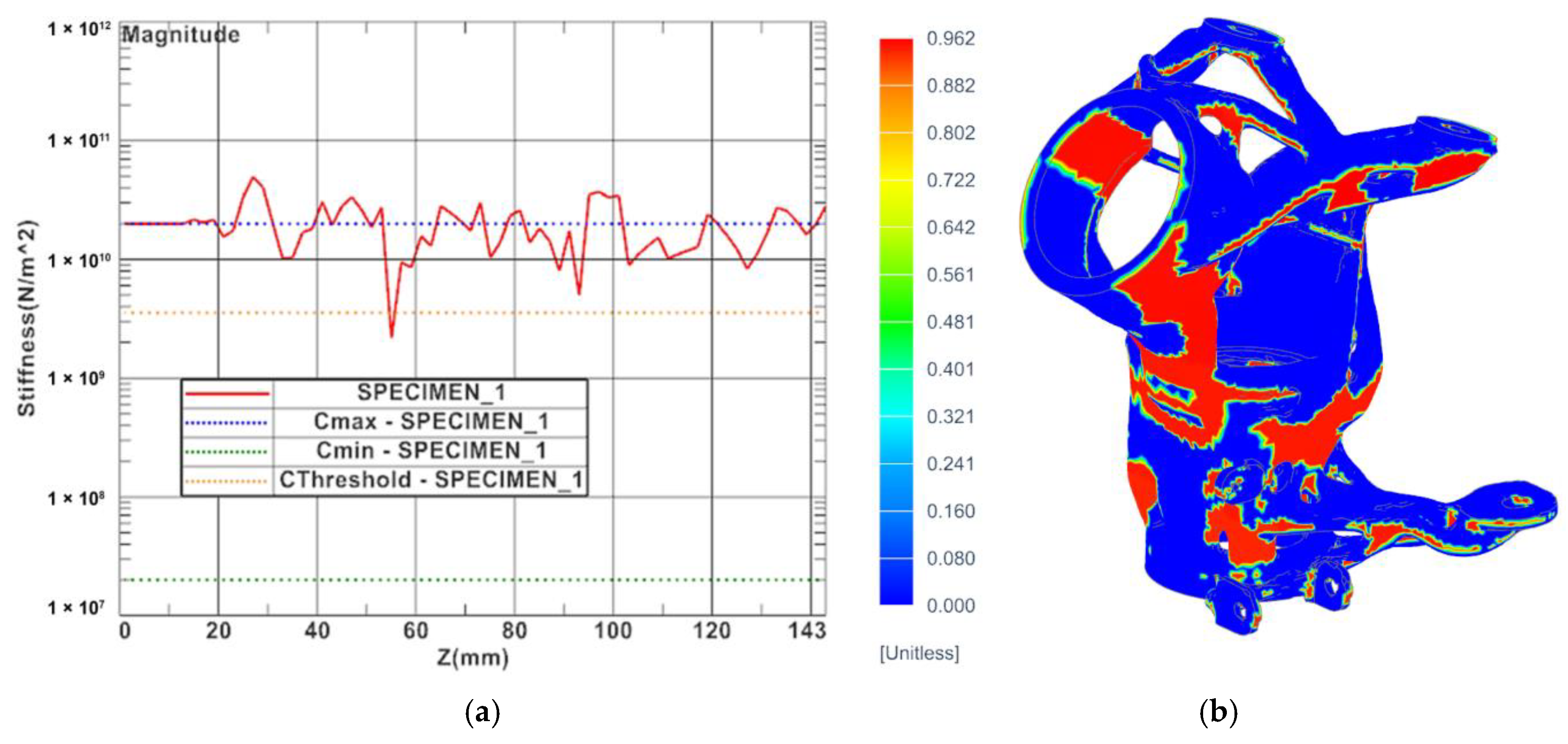
The stiffness curves and local overheating results were generated as additional results of the numerical simulations. The stiffness curve is a 2D curve with layer stiffness information that allows identification of the areas of potential severe distortion or shrink defects. Both results are given in Figure 13.
The last result of the additive manufacturing analysis was checking the possibility of re-coater collision, which also confirmed the suitability of setting up the solution. The input model with compensation from distortion results of the mechanical analysis was exported for fabrication of the function specimen. The distortion compensation was carried out by inverting the distortion prediction and applying the inversion to the nominal target geometry.

4.3. Fabrication of Functional Specimen

The functional specimen was fabricated using the industrial 3D printing machine EOS M 290, which uses the L-PBF printing method. The process parameters for printing were chosen the same as for test samples and numerical simulations (see Table 3). The thermal treatment known as ageing was employed during the production of our component using DMLS technology for the AlSi10Mg material. After the AlSi10Mg material was printed, it underwent a natural ageing process that involved heating the component at an elevated temperature followed by gradual cooling. This thermal process enhances the mechanical properties, such as strength and hardness, of the material. The functional specimen of the steering column housing was (after trimming supports) machined in connection areas using a five-axis CNC machine.
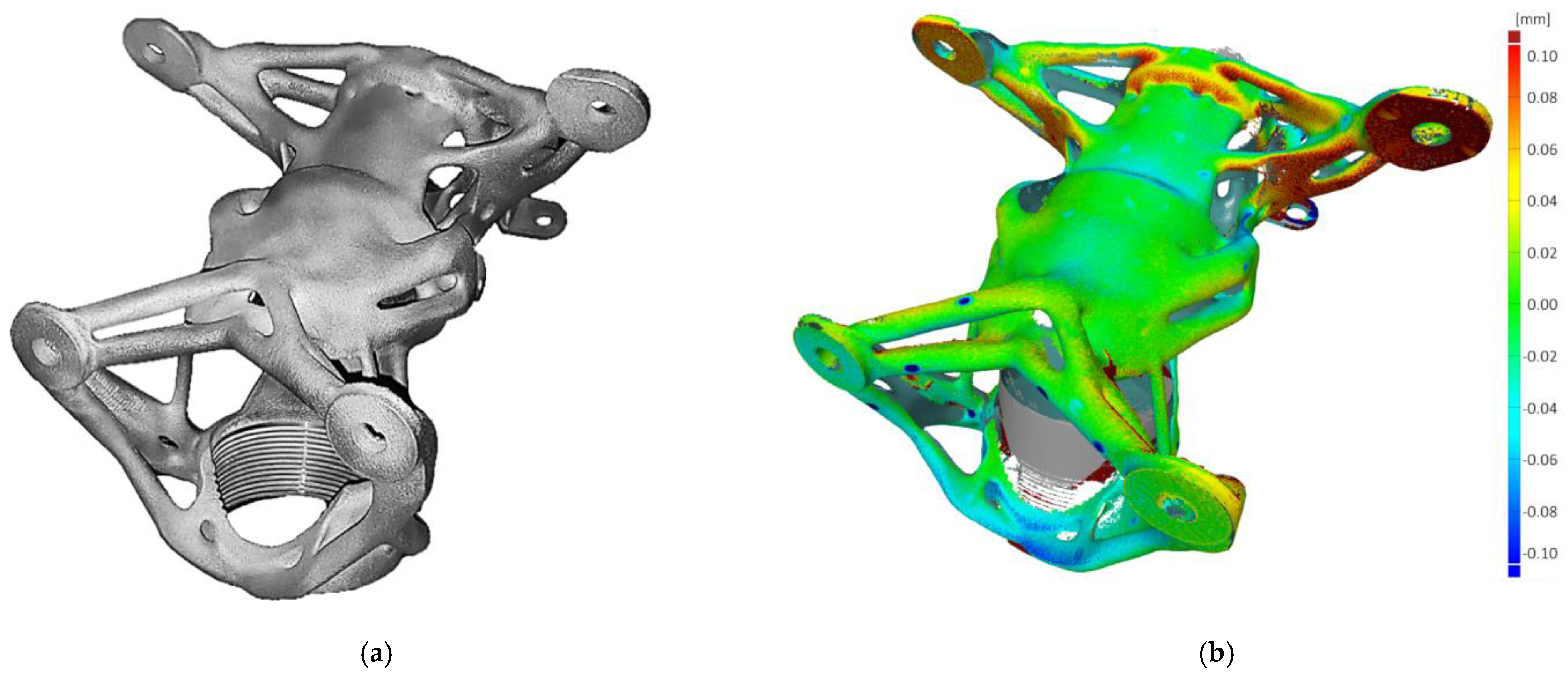
A 3D scan measurement of the printed functional specimen was performed on a CMM Carl Zeiss Prismo 7 Navigator machine for comparison with results and validation of the compensation (numerical simulation). Very good agreement was found with a deviation in the main functional areas of only up to 0.11 mm. The final functional specimen and comparison of the real state (3D scan) with the original structure of the optimization are shown in Figure 14.

5. Discussion

The successful validation of the proposed methodology for topology optimization and direct additive manufacturing using DMLS was confirmed through extensive testing on the functional sample. The entire process can be divided into four key phases: optimization, verification, distortion compensation, and validation, as depicted in the flowchart illustrated in Figure 15.
To assess the real-world performance of the optimized design, the functional specimen was integrated into the latest generation of the formula student racing car UWB06 and subjected to rigorous testing under actual driving conditions, accumulating over 200 h of active use. These tests closely replicated the forces and stresses predicted by the structural analyses, as determined from telemetry data.
Following the active testing phase, a non-destructive liquid-dye penetrant test was conducted to identify any potential surface cracks on the housing. The results were highly satisfactory, indicating the absence of any detectable flaws. Subsequently, the optimized steering column housing successfully underwent official races without encountering any complications.
The successful implementation of the proposed methodology, coupled with its impressive performance in real-world racing scenarios, highlights its potential for advancing the field of additive manufacturing and optimization in motorsport applications. These findings pave the way for further exploration and development in the pursuit of enhanced performance and reliability.
The inclusion of fatigue analysis in the methodology, whether through the development of new approaches or the extension of existing ones, presents significant opportunities for further research and advancements in the field. By considering the effects of material fatigue, it opens doors to explore new frontiers and deepen our understanding of component behavior under cyclic loading conditions.
The overall process time consists of three main stages: topology optimization, print simulation, and actual manufacturing. The time savings associated with eliminating the need to export and import data between different stages are 6 h. The time saved by avoiding the need for remodeling is 32 h. Approximately 38 h were saved with the usage of the presented methodology. The total time saved depends on the complexity of the parts, but in general, it can be said that the more complex the design, the greater the amount of time saved.

6. Conclusions

The paper presents a novel methodology for utilizing the results of topology optimization directly in additive manufacturing (L-PBF) without the need for remodeling the final structure. A case study involving the steering column housing exemplifies the application of this process. The optimal shape was obtained using topology optimization in Siemens NX 1888 Software, with consideration of additive manufacturing constraints. To verify the suitability of the resulting structure, the normalized material data from topology optimization were converted into a convergent body for verification analysis. The FEM-based solver NX Nastran verified the obtained design. Furthermore, numerical simulations of the printing process were conducted to address potential printing issues such as thermal distortion, overheating areas, and shrinking lines.
The proposed methodology demonstrated significant time savings in the overall design process, particularly by eliminating the need for remodeling the resulting structure obtained from topological optimization. However, this advantage is simultaneously associated with a major limitation of the proposed methodology. As the obtained structure is very challenging to edit, it becomes highly problematic to modify the final geometry in terms of functionality, especially if it does not fully meet the requirements after verification analysis. Furthermore, applying shape optimization to the remodeled structure easily resolves critical areas with high stress concentrations.
To validate the methodology, a functional specimen of the steering column housing was fabricated using AlSi10Mg on an EOS M 290 3D printer. The printed part was then 3D-scanned to assess distortion, and it underwent extensive testing during a full season in the single-seat formula student racing car UWB06. Remarkably, the component endured over 200 h of active driving in both testing and official races without any complications.

Author Contributions

Conceptualization, F.S.; methodology, F.S. and T.K.; numerical simulations, F.S. and M.S.; experimental data processing, F.S. and M.S.; writing—original draft preparation, F.S. and M.S. All authors have read and agreed to the published version of the manuscript.

Funding

This work was supported by the Grant Agency of the University of West Bohemia, grant No. SGS-2022-009—Comprehensive support for the construction of technical equipment V.

Institutional Review Board Statement

Not applicable.

Informed Consent Statement

Not applicable.

Data Availability Statement

Not applicable.

Acknowledgments

The article has been prepared under project SGS-2022-009—Comprehensive support for the construction of technical equipment V.

Conflicts of Interest

The authors declare no conflict of interest.

References

  1. Cao, B.; Zhao, J.; Yang, P.; Gu, Y.; Muhammad, K.; Rodrigues, J.J.P.C.; De Albuquerque, V.H.C. Multiobjective 3-D Topology Optimization of Next-Generation Wireless Data Center Network. IEEE Trans. Ind. Inf. 2020, 16, 3597–3605. [Google Scholar] [CrossRef]
  2. Galilei, G.; Elzevir, B.; Elzevir, A. Discorsi e Dimostrazioni Matematiche Intorno à Due Nuoue Scienze, Attenenti Alla Mecanica & i Movimenti Locali; Elsevier: Leida, The Netherlands, 1638; ISBN 978-1-4832-8527-6. [Google Scholar]
  3. Michell, A.G.M. LVIII. The Limits of Economy of Material in Frame-Structures. Lond. Edinb. Dublin Philos. Mag. J. Sci. 1904, 8, 589–597. [Google Scholar] [CrossRef] [Green Version]
  4. Raz, K.; Hora, J.; Pavlata, P. Unconventional Materials Usage in Design of Vehicle Bodies. Manuf. Technol. 2017, 17, 823–827. [Google Scholar] [CrossRef]
  5. Rao, S.S. Engineering Optimization: Theory and Practice, 4th ed.; Wiley: Hoboken, NJ, USA, 2009; ISBN 978-0-470-18352-6. [Google Scholar]
  6. Goncharov, P. Engineering Analysis with NX Advanced Simulation; Lulu Press: Raleigh, NC, USA, 2014. [Google Scholar]
  7. Kim, H.-G.; Nerse, C.; Wang, S. Topography Optimization of an Enclosure Panel for Low-Frequency Noise and Vibration Reduction Using the Equivalent Radiated Power Approach. Mater. Des. 2019, 183, 108125. [Google Scholar] [CrossRef]
  8. Papadrakakis, M.; Tsompanakis, Y.; Hinton, E.; Sienz, J. Advanced Solution Methods in Topology Optimization and Shape Sensitivity Analysis. Eng. Comput. 1996, 13, 57–90. [Google Scholar] [CrossRef]
  9. Xiao, Z.; Yang, Y.; Wang, D.; Song, C.; Bai, Y. Structural Optimization Design for Antenna Bracket Manufactured by Selective Laser Melting. Rapid Prototyp. J. 2018, 24, 539–547. [Google Scholar] [CrossRef]
  10. Bendsoe, M.P.; Sigmund, O. Topology Optimization: Theory, Methods, and Applications, 2nd ed.; Springer: Berlin/Heidelberg, Germany, 2004; ISBN 978-3-540-42992-0. [Google Scholar]
  11. Prager, W.; Rozvany, G.I.N. Optimization of Structural Geometry. In Dynamical Systems; Bednarek, A.R., Cesari, L., Eds.; Academic Press: Cambridge, MA, USA, 1977; pp. 265–293. ISBN 978-0-12-083750-2. [Google Scholar]
  12. Tang, Y.; Zhao, Y.F. A Survey of the Design Methods for Additive Manufacturing to Improve Functional Performance. Rapid Prototyp. J. 2016, 22, 569–590. [Google Scholar] [CrossRef]
  13. Rozvany, G.I.N. A Critical Review of Established Methods of Structural Topology Optimization. Struct. Multidisc. Optim. 2009, 37, 217–237. [Google Scholar] [CrossRef]
  14. Bendsøe, M.P.; Sigmund, O. Material Interpolation Schemes in Topology Optimization. Arch. Appl. Mech. (Ing. Arch.) 1999, 69, 635–654. [Google Scholar] [CrossRef]
  15. Bendsøe, M.P. Optimal Shape Design as a Material Distribution Problem. Struct. Optim. 1989, 1, 193–202. [Google Scholar] [CrossRef]
  16. Zhou, M.; Rozvany, G.I.N. The COC Algorithm, Part II: Topological, Geometrical and Generalized Shape Optimization. Comput. Methods Appl. Mech. Eng. 1991, 89, 309–336. [Google Scholar] [CrossRef]
  17. Stolpe, M.; Svanberg, K. An Alternative Interpolation Scheme for Minimum Compliance Topology Optimization. Struct. Multidiscip. Optim. 2001, 22, 116–124. [Google Scholar] [CrossRef]
  18. Allaire, G. The Homogenization Method for Topology and Shape Optimization. In Topology Optimization in Structural Mechanics; Springer: Vienna, Austria, 1997; pp. 101–133. [Google Scholar]
  19. Beckers, M.; Fleury, C. Topology Optimization Involving Discrete Variables. In Proceedings of the Second World Congress of Structural and Multidisciplinary Optimization, Zakopane, Poland, 26–30 May 1997; Polish Academy of Sciences, Institute of Fundamental Technological Research: Warszawa, Poland, 1997; pp. 533–538. [Google Scholar]
  20. Xie, Y.M.; Huang, X. Recent Developments in Evolutionary Structural Optimization (ESO) for Continuum Structures. In Proceedings of the IOP Conference Series: Materials Science and Engineering; IOP Publishing: Bristol, UK, 2010; Volume 10, p. 012196. [Google Scholar]
  21. Querin, O.M.; Young, V.; Steven, G.P.; Xie, Y.M. Computational Efficiency and Validation of Bi-Directional Evolutionary Structural Optimisation. Comput. Methods Appl. Mech. Eng. 2000, 189, 559–573. [Google Scholar] [CrossRef]
  22. Querin, O.M.; Steven, G.P.; Xie, Y.M. Evolutionary Structural Optimisation Using an Additive Algorithm. Finite Elem. Anal. Des. 2000, 34, 291–308. [Google Scholar] [CrossRef]
  23. ASTM F2792-12a; Terminology for Additive Manufacturing Technologies. ASTM International: West Conshohocken, PA, USA, 2012.
  24. Bull, G.; Haj-Hariri, H.; Atkins, R.; Moran, P. An Educational Framework for Digital Manufacturing in Schools. 3D Print. Addit. Manuf. 2015, 2, 42–49. [Google Scholar] [CrossRef]
  25. Scott, A.; Harrison, T.P. Additive Manufacturing in an End-to-End Supply Chain Setting. 3D Print. Addit. Manuf. 2015, 2, 65–77. [Google Scholar] [CrossRef]
  26. Seepersad, C.C. Challenges and Opportunities in Design for Additive Manufacturing. 3D Print. Addit. Manuf. 2014, 1, 10–13. [Google Scholar] [CrossRef]
  27. Gordon, R. Trends in Commercial 3D Printing and Additive Manufacturing. 3D Print. Addit. Manuf. 2015, 2, 89–90. [Google Scholar] [CrossRef]
  28. Hosny, A.; Keating, S.J.; Dilley, J.D.; Ripley, B.; Kelil, T.; Pieper, S.; Kolb, D.; Bader, C.; Pobloth, A.-M.; Griffin, M.; et al. From Improved Diagnostics to Presurgical Planning: High-Resolution Functionally Graded Multimaterial 3D Printing of Biomedical Tomographic Data Sets. 3D Print. Addit. Manuf. 2018, 5, 103–113. [Google Scholar] [CrossRef]
  29. ISO 17296:2015; Additive Manufacturing—General Principles—Part 2: Overview of Process Categories and Feedstock. ISO: Geneva, Switzerland, 2015.
  30. ISO/ASTM 52901:2017; Additive Manufacturing—General Principles—Requirements for Purchased AM Parts. ISO: Geneva, Switzerland, 2017.
  31. Barnatt, C. 3D Printing: Third Edition; CreateSpace Independent Publishing Platform: Scotts Valey, CA, USA, 2016; ISBN 978-1-5396-5546-6. [Google Scholar]
  32. ISO/ASTM 52915:2013; Standard Specification for Additive Manufacturing File Format. ISO: Geneva, Switzerland, 2013.
  33. ISO/ASTM 52900-15; Standard Terminology for Additive Manufacturing–General Principles–Terminology. ASTM International: West Conshohocken, PA, USA, 2015.
  34. Chia, H.N.; Wu, B.M. Recent Advances in 3D Printing of Biomaterials. J. Biol. Eng. 2015, 9, 4. [Google Scholar] [CrossRef] [Green Version]
  35. Snyder, T.J.; Andrews, M.; Weislogel, M.; Moeck, P.; Stone-Sundberg, J.; Birkes, D.; Hoffert, M.P.; Lindeman, A.; Morrill, J.; Fercak, O.; et al. 3D Systems’ Technology Overview and New Applications in Manufacturing, Engineering, Science, and Education. 3D Print. Addit. Manuf. 2014, 1, 169–176. [Google Scholar] [CrossRef]
  36. Dul, S.; Fambri, L.; Pegoretti, A. Fused Deposition Modelling with ABS–Graphene Nanocomposites. Compos. Part A Appl. Sci. Manuf. 2016, 85, 181–191. [Google Scholar] [CrossRef]
  37. Chacón, J.M.; Caminero, M.A.; García-Plaza, E.; Núñez, P.J. Additive Manufacturing of PLA Structures Using Fused Deposition Modelling: Effect of Process Parameters on Mechanical Properties and Their Optimal Selection. Mater. Des. 2017, 124, 143–157. [Google Scholar] [CrossRef]
  38. Chua, C.K.; Leong, K.F. 3D Printing and Additive Manufacturing: Principles and Applications (with Companion Media Pack) Fourth Edition of Rapid Prototyping, 4th ed.; World Scientific Publishing Company: Singapore, 2014; ISBN 978-981-4578-49-3. [Google Scholar]
  39. Quetzeri-Santiago, M.A.; Hedegaard, C.L.; Castrejón-Pita, J.R. Additive Manufacturing with Liquid Latex and Recycled End-of-Life Rubber. 3D Print. Addit. Manuf. 2019, 6, 149–157. [Google Scholar] [CrossRef] [Green Version]
  40. Miyanaji, H.; Zhang, S.; Lassell, A.; Zandinejad, A.; Yang, L. Process Development of Porcelain Ceramic Material with Binder Jetting Process for Dental Applications. JOM 2016, 68, 831–841. [Google Scholar] [CrossRef]
  41. Zhou, Y.; Tang, Y.; Hoff, T.; Garon, M.; Zhao, F.Y. The Verification of the Mechanical Properties of Binder Jetting Manufactured Parts by Instrumented Indentation Testing. Procedia Manuf. 2015, 1, 327–342. [Google Scholar] [CrossRef] [Green Version]
  42. Mani, M.; Feng, S.; Lane, B.; Donmez, A.; Moylan, S.; Fesperman, R. Measurement Science Needs for Real-Time Control of Additive Manufacturing Powder Bed Fusion Processes; US Department of Commerce, National Institute of Standards and Technology: Gaithersburg, MD, USA, 2015. [Google Scholar]
  43. Chen, L.Y.; Huang, J.C.; Lin, C.H.; Pan, C.T.; Chen, S.Y.; Yang, T.L.; Lin, D.Y.; Lin, H.K.; Jang, J.S.C. Anisotropic Response of Ti-6Al-4V Alloy Fabricated by 3D Printing Selective Laser Melting. Mater. Sci. Eng. A 2017, 682, 389–395. [Google Scholar] [CrossRef]
  44. Brandt, M. (Ed.) Laser Additive Manufacturing: Materials, Design, Technologies, and Applications; Woodhead Publishing Series in Electronic and Optical Materials; Elsevier/Woodhead Publishing: Boston, MA, USA, 2017; ISBN 978-0-08-100433-3. [Google Scholar]
  45. Sutton, A.T.; Kriewall, C.S.; Leu, M.C.; Newkirk, J.W. Powder Characterisation Techniques and Effects of Powder Characteristics on Part Properties in Powder-Bed Fusion Processes. Virtual Phys. Prototyp. 2017, 12, 3–29. [Google Scholar] [CrossRef]
  46. Heigel, J.C.; Michaleris, P.; Reutzel, E.W. Thermo-Mechanical Model Development and Validation of Directed Energy Deposition Additive Manufacturing of Ti–6Al–4V. Addit. Manuf. 2015, 5, 9–19. [Google Scholar] [CrossRef]
  47. Ahmed, N. Direct Metal Fabrication in Rapid Prototyping: A Review. J. Manuf. Process. 2019, 42, 167–191. [Google Scholar] [CrossRef]
  48. ISO/ASTM 52900:2015; Additive Manufacturing—General Principles—Terminology. ISO: Geneva, Switzerland, 2015.
  49. Rokicki, P.; Kozik, B.; Budzik, G.; Dziubek, T.; Bernaczek, J.; Przeszlowski, L.; Markowska, O.; Sobolewski, B.; Rzucidlo, A. Manufacturing of Aircraft Engine Transmission Gear with SLS (DMLS) Method. Aircr. Eng. Aerosp. Technol. Int. J. 2016, 88, 397–403. [Google Scholar] [CrossRef]
  50. Rahmati, S. Direct Rapid Tooling. In Comprehensive Materials Processing; Elsevier: Amsterdam, The Netherlands, 2014; pp. 303–344. ISBN 978-0-08-096533-8. [Google Scholar]
  51. Korkmaz, M.E.; Gupta, M.K.; Robak, G.; Moj, K.; Krolczyk, G.M.; Kuntoğlu, M. Development of Lattice Structure with Selective Laser Melting Process: A State of the Art on Properties, Future Trends and Challenges. J. Manuf. Process. 2022, 81, 1040–1063. [Google Scholar] [CrossRef]
  52. Prathyusha, A.L.R.; Raghu Babu, G. A Review on Additive Manufacturing and Topology Optimization Process for Weight Reduction Studies in Various Industrial Applications. Mater. Today Proc. 2022, 62, 109–117. [Google Scholar] [CrossRef]
  53. Prathyusha, A.; Babu, G.R. 3D Printing Integration with Topology Optimization for Innovative Design and Fabrication of Light Weight Aerospace Structures. In Proceedings of the 2022 International Conference on Recent Trends in Microelectronics, Automation, Computing and Communications Systems (ICMACC), Hyderabad, India, 28–30 December 2022; IEEE: Piscataway, NJ, USA, 2022; pp. 1–6. [Google Scholar]
  54. Dienemann, R.; Schewe, F.; Elham, A. Industrial Application of Topology Optimization for Forced Convection Based on Darcy Flow. Struct. Multidisc. Optim. 2022, 65, 265. [Google Scholar] [CrossRef]
  55. Barbieri, L.; Muzzupappa, M. Performance-Driven Engineering Design Approaches Based on Generative Design and Topology Optimization Tools: A Comparative Study. Appl. Sci. 2022, 12, 2106. [Google Scholar] [CrossRef]
  56. Kim, J.; Park, J.H.; Jang, S.; Jeong, H.; Kim, T.; Kim, H.G. Effect of Support Structures on the Deformation of AlSi10Mg Aircraft Parts Made Using DMLS. Int. J. Precis. Eng. Manuf. 2023, 24, 837–851. [Google Scholar] [CrossRef]
  57. Bouabbou, A.; Vaudreuil, S. Understanding Laser-Metal Interaction in Selective Laser Melting Additive Manufacturing through Numerical Modelling and Simulation: A Review. Virtual Phys. Prototyp. 2022, 17, 543–562. [Google Scholar] [CrossRef]
  58. Azami, M.; Siahsarani, A.; Hadian, A.; Kazemi, Z.; Rahmatabadi, D.; Kashani-Bozorg, S.F.; Abrinia, K. Laser Powder Bed Fusion of Alumina/Fe–Ni Ceramic Matrix Particulate Composites Impregnated with a Polymeric Resin. J. Mater. Res. Technol. 2023, 24, 3133–3144. [Google Scholar] [CrossRef]
  59. Ghasri-Khouzani, M.; Peng, H.; Attardo, R.; Ostiguy, P.; Neidig, J.; Billo, R.; Hoelzle, D.; Shankar, M.R. Comparing Microstructure and Hardness of Direct Metal Laser Sintered AlSi10Mg Alloy between Different Planes. J. Manuf. Process. 2019, 37, 274–280. [Google Scholar] [CrossRef]
  60. Krishnan, M.; Atzeni, E.; Canali, R.; Calignano, F.; Manfredi, D.; Ambrosio, E.P.; Iuliano, L. On the Effect of Process Parameters on Properties of AlSi10Mg Parts Produced by DMLS. Rapid Prototyp. J. 2014, 20, 449–458. [Google Scholar] [CrossRef]
  61. Montanari, R.; Palombi, A.; Richetta, M.; Varone, A. Additive Manufacturing of Aluminum Alloys for Aeronautic Applications: Advantages and Problems. Metals 2023, 13, 716. [Google Scholar] [CrossRef]
  62. ASTM E8/E8M-16a; Standard Test Methods for Tension Testing of Metallic Materials. ASTM International: West Conshohocken, PA, USA, 2016.
  63. Alsalla, H.H.; Smith, C.; Hao, L. The Effect of Different Build Orientations on the Consolidation, Tensile and Fracture Toughness Properties of Direct Metal Laser Sintering Ti-6Al-4V. Rapid Prototyp. J. 2018, 24, 276–284. [Google Scholar] [CrossRef]
  64. Promoppatum, P.; Yao, S.-C. Influence of Scanning Length and Energy Input on Residual Stress Reduction in Metal Additive Manufacturing: Numerical and Experimental Studies. J. Manuf. Process. 2020, 49, 247–259. [Google Scholar] [CrossRef]
  65. Špirk, S.; Špička, J.; Vychytil, J.; Křížek, M.; Stehlík, A. Utilization of the Validated Windshield Material Model in Simulation of Tram to Pedestrian Collision. Materials 2021, 14, 265. [Google Scholar] [CrossRef]
  66. Rypl, D.; Bittnar, Z. Generation of Computational Surface Meshes of STL Models. J. Comput. Appl. Math. 2006, 192, 148–151. [Google Scholar] [CrossRef]
  67. Zienkiewicz, O.C.; Taylor, R.L.; Zhu, J.Z. The Finite Element Method: Its Basis and Fundamentals, 7th ed.; Butterworth-Heinemann: Amsterdam, The Netherlands, 2013; ISBN 978-1-85617-633-0. [Google Scholar]
  68. Liu, Y.; Li, Z.; Wei, P.; Chen, S. Generating Support Structures for Additive Manufacturing with Continuum Topology Optimization Methods. Rapid Prototyp. J. 2018, 25, 232–246. [Google Scholar] [CrossRef]
  69. Jiang, J.; Stringer, J.; Xu, X. Support Optimization for Flat Features via Path Planning in Additive Manufacturing. 3D Print. Addit. Manuf. 2019, 6, 171–179. [Google Scholar] [CrossRef] [Green Version]
  70. Hildreth, O.J.; Nassar, A.R.; Chasse, K.R.; Simpson, T.W. Dissolvable Metal Supports for 3D Direct Metal Printing. 3D Print. Addit. Manuf. 2016, 3, 90–97. [Google Scholar] [CrossRef]
  71. Lefky, C.S.; Zucker, B.; Wright, D.; Nassar, A.R.; Simpson, T.W.; Hildreth, O.J. Dissolvable Supports in Powder Bed Fusion-Printed Stainless Steel. 3D Print. Addit. Manuf. 2017, 4, 3–11. [Google Scholar] [CrossRef] [Green Version]
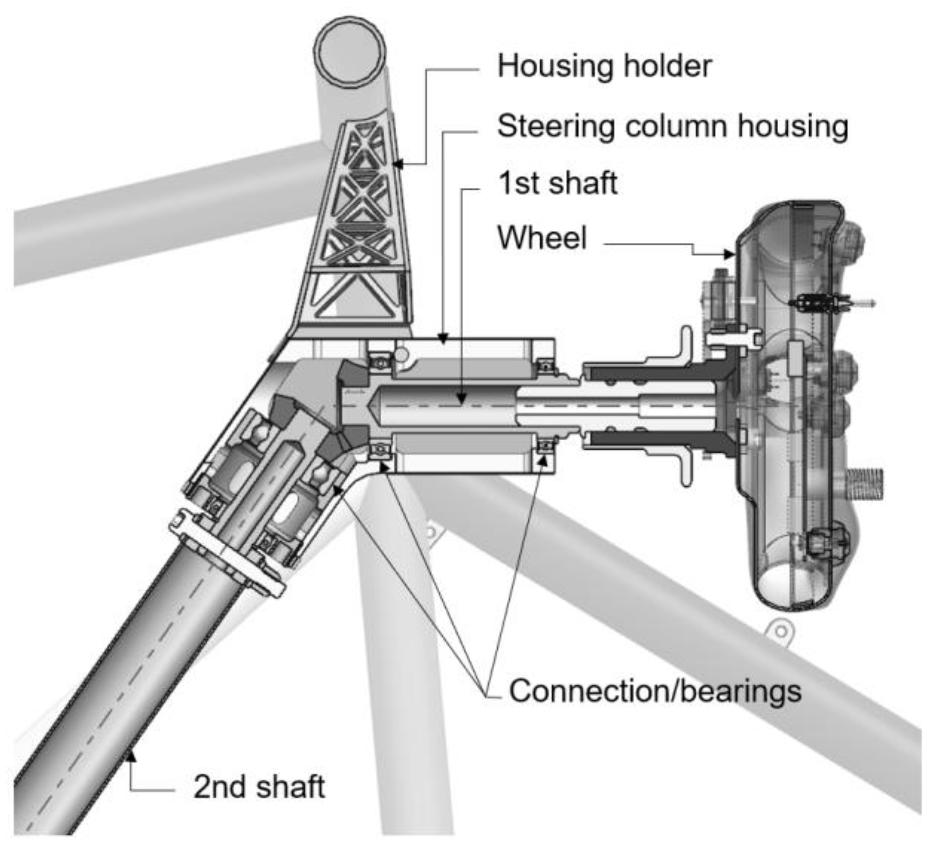
Figure 1. Schematic of current solution of steering column housing and connected components.
Materials 16 05422 g001
Figure 2. Engineering and true stress–strain curves of vertically and horizontally printed AlSi10Mg specimens.
Materials 16 05422 g002
Figure 3. (a) Three-dimensional model of boundary volume for topology optimization; (b) frozen areas of topology optimization.
Materials 16 05422 g003
Figure 4. The final structure of the topology optimization.
Materials 16 05422 g004
Figure 5. Main types of STL errors.
Materials 16 05422 g005
Figure 6. (a) Generated convergence model; (b) FEM mesh for verification analysis.
Materials 16 05422 g006
Figure 7. The results of structural analysis of the steering column housing for the most critical load case: (a) displacement—magnitude (m); (b) equivalent tensile stress—according to Von Mises (MPa).
Materials 16 05422 g007
Figure 8. Optimization of orientation of part relative to printing bed, (a) results of individual optimization categories (minimum, maximum and selected), (b) resulting optimized part position.
Materials 16 05422 g008
Figure 9. Final orientation of model with generated block supports for AM fabrication.
Materials 16 05422 g009
Figure 10. Flowchart of numerical simulation of printing process.
Materials 16 05422 g010
Figure 11. Thermal analysis results of printed specimen: (a) specimen with supports; (b) specimen after support removal.
Materials 16 05422 g011
Figure 12. Results of distortion of printed part: (a) distortion after printing, (b) distortion after cool down, and (c) distortion after support removal.
Materials 16 05422 g012
Figure 13. Additional results of numerical simulation: (a) stiffness curve of printed part and (b) probability of local overheating.
Materials 16 05422 g013
Figure 14. Functional specimen of the steering column housing: (a) 3D-printed functional specimen and (b) results of deviation.
Materials 16 05422 g014
Figure 15. Flowchart of basic methodology of product optimization for direct additive manufacturing by L-PBF.
Materials 16 05422 g015
Table 1. Chemical composition of AlSi10Mg (wt.%).
AlSiMgFeTiCuMnZn
Balanced9.90.430.24<0.01<0.005<0.005<0.002
Table 2. Process parameters of AlSi10mg specimens.
Power
(W)
Scan Rate (mm/s)Layer Thickness
(µm)
Hatch Distance (µm)Platform Temperature (°C)
370115030100150
Table 3. Mechanical properties of AlSi10Mg (EOS M 290) of the vertically and horizontally printed specimens.
ParameterPrint DirectionDescription
VPSHPS
ρ (kg/m3) 2670Density
E (MPa)7069Modulus of elasticity
ν (-)0.29Poisson’s ratio
Rp0.2% (MPa)192224Yield strength
σ k (MPa) 468471Tensile strength
ε k (%) 9 ± 211 ± 2Elongation at break
Table 4. Process/thermal parameters of AlSi10Mg (EOS M 290) used for numerical simulation.
ParameterValueDescription
tR (s)12.25Recoating time
TBP (°C)147Base-plate temperature
TA (°C)46.85Ambient temperature
hHTC (W/(m.K))20Ambient Gas HT
αBP (°C−1)1.20e−05Build plate/printer alpha
nPL1Number of lasers of printer
Disclaimer/Publisher’s Note: The statements, opinions and data contained in all publications are solely those of the individual author(s) and contributor(s) and not of MDPI and/or the editor(s). MDPI and/or the editor(s) disclaim responsibility for any injury to people or property resulting from any ideas, methods, instructions or products referred to in the content.