Article

The Influence of Annealing and Film Thickness on the Specific Properties of Co40Fe40Y20 Films

1
Department of Materials Science and Engineering, I-Shou University, Kaohsiung City 840, Taiwan
2
Bachelor Program in Interdisciplinary Studies, National Yunlin University of Science and Technology, 123 University Road, Section 3, Douliou, Yunlin 64002, Taiwan
3
Department of Mechanical Engineering, National Kaohsiung University of Science and Technology, Kaohsiung City 80778, Taiwan
4
Graduate School of Materials Science, National Yunlin University of Science and Technology, 123 University Road, Section 3, Douliou, Yunlin 64002, Taiwan
5
Institute of Physics, Academia Sinica, Nankang, Taipei 11529, Taiwan
*
Author to whom correspondence should be addressed.
Materials 2023, 16(6), 2490; https://doi.org/10.3390/ma16062490
Submission received: 24 February 2023 / Revised: 20 March 2023 / Accepted: 20 March 2023 / Published: 21 March 2023

Abstract

:
Cobalt Iron Yttrium (CoFeY) magnetic film was made using the sputtering technique in order to investigate the connection between the thickness and annealing procedures. The sample was amorphous as a result of an insufficient thermal driving force according to X-ray diffraction (XRD) examination. The maximum low-frequency alternate-current magnetic susceptibility (χac) values were raised in correlation with the increased thickness and annealing temperatures because the thickness effect and Y addition improved the spin exchange coupling. The best value for a 50 nm film at annealing 300 °C for χac was 0.20. Because electron carriers are less constrained in their conduction at thick film thickness and higher annealing temperatures, the electric resistivity and sheet resistance are lower. At a thickness of 40 nm, the film’s maximum surface energy during annealing at 300 °C was 28.7 mJ/mm2. This study demonstrated the passage of photon signals through the film due to the thickness effect, which reduced transmittance. The best condition was found to be 50 nm with annealing at 300 °C in this investigation due to high χac, strong adhesion, and low resistivity, which can be used in magnetic fields.

Graphical Abstract

1. Introduction

The high saturation magnetization (Ms) and low coercivity (Hc) are just two of the desirable soft magnetic properties of Cobalt Iron (CoFe) material as an over-alloy [1,2,3]. These characteristics of CoFe alloys are mostly used in composite permanent magnets, catalysts, and magnetic equipment. Additionally, soft magnetic materials can be used in thin films, which are then used in magnetic applications like sensors, actuators, magnetic reading heads, and magnetic random access memory (MRAM) [4,5,6,7,8]. However, CoFe films have fatal disadvantages at high temperatures, such as magnetic anisotropy degradation. After annealing at a particular temperature, thermal stability must be improved for the effective use of magnetic devices, so adding a third element may be one of the solutions to this problem [9,10,11]. When applying a magnetic film at a high temperature, it is vital to determine whether the magnetic film will be impacted by the thermal effect. The service life and durability of the magnetic components are important reference indices. Rare earth (RE) metals that are ferromagnetic typically have unique features that can be utilized to increase performance at high temperatures. The mechanical qualities of the alloy can be increased by including the rare earth element Yttrium (Y), which also has strong heat stability and corrosion resistance. The mechanical and toughness characteristics of the parent alloy may be enhanced by the Y addition. Additionally, this may facilitate the processing of the alloy and increase its resistance to oxidation under high temperatures [12,13,14,15,16]. Despite its abundance among rare earth elements, Y has received little attention. Significant characteristics are considerably improved by the addition of Y and heat treatment. By enhancing the exchange coupling effect, Y substitution can have an effect on remanence, magnetic energy, and thermal stability [17,18]. When pure Y is exposed to air, it spontaneously produces yttrium oxide (Y2O3), which has exceptional thermal stability, mechanical capabilities, as well as optical and electrical properties. The heat barrier layer is frequently made of Y2O3 film, which can also be utilized as a light anti-reflective layer [19,20,21,22]. In a magnetic tunneling junction (MTJ), a cobalt iron boron (Co40Fe40B20) thin film is typically encountered as a free or pinned layer. In order to enhance magnetic properties, Cobalt Iron Yttrium (CoFeY) films were mostly used in this work with the same Y/B ratio. The goal of this research is to see if annealed CoFeY thin films change in high-temperature environments by looking at their structure and magnetic characteristics. The creation of Co40Fe40Y20 films and whether adding Y can enhance the performance of these materials have been the main topics of our research up to this point. As a result, there has been minimal research in this field. It is critical to explore the properties of Co40Fe40Y20 films produced by sputtering at room temperature (RT) and annealing processes. At various thicknesses, the magnetic characteristics, adhesion, and optical performance of as-deposited and annealed films were also investigated. It is significant to note that when a CoFeB seed or buffer layer was replaced with a CoFeY film, the thermal stability of the CoFeY films was improved, making these materials more suitable for use in actual MTJ applications. Table 1 contains the abbreviations and full names of the proper nouns. In earlier studies, the magnetic and adhesion characteristics of CoFeY materials were compared to those of Cobalt Iron Vanadium (CoFeV), Cobalt Iron Tungsten (CoFeW), and Cobalt Iron Ytterbium (CoFeYb) in Table 2 [23,24,25,26,27]. In contrast to previous CoFeY films that were sputtered on Si(100) substrates to study magnetic and adhesion outcomes, the goal of this research is to produce thin films on glass substrates and also investigate optical transmittance properties. Additionally, contact angle measurements are a suitable and simple way to determine the surface energy using water and glycerol when taking into account the application of the film, which is a dominant factor in molecular interaction at the surface [28]. In most cases, researchers have emphasized the properties in light of the magnetic hysteresis curve, Ms, and Hc [29,30,31]. However, it will be interesting to learn how the variation of surface energy and optical transmittance can be correlated with the magnetic properties of the deposited films.

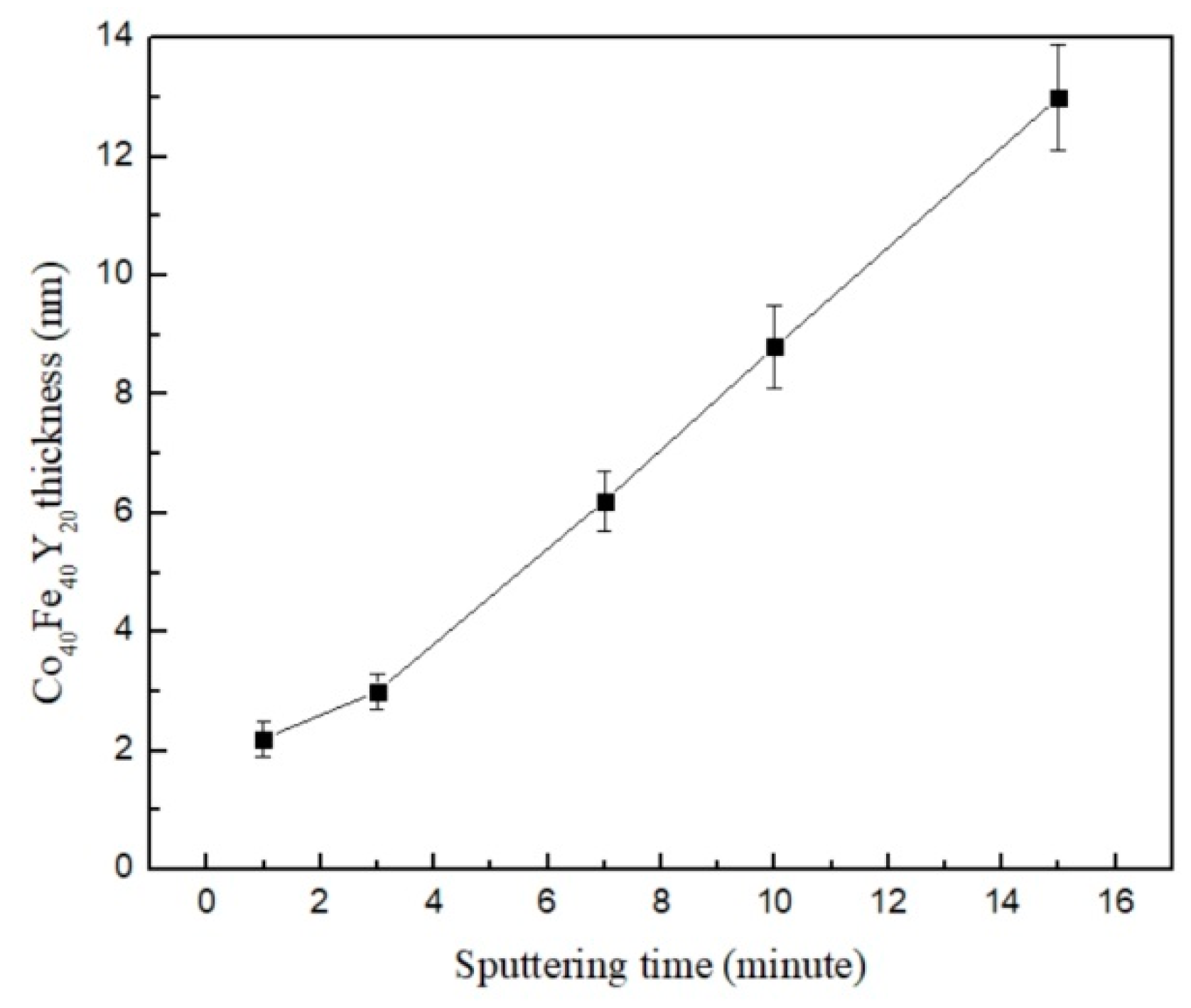
2. Materials and Methods

CoFeY films with thicknesses varying from 10 nm to 50 nm were sputtered at RT on a glass substrate by using a magnetron sputtering direct current (DC) approach. The investigations were carried out on the as-deposited films and after various annealed treatments at 100 °C, 200 °C, and 300 °C for 1 h in an Argon (Ar) environment. The Ar working pressure was 3 × 10⁻³ Torr, while the base pressure of the chamber was 3 × 10⁻⁷ Torr. There was 2.5 × 10⁻³ Torr of pressure in the ex situ annealed state. The experimental target is made of a variety of sintered materials. The distance between the substrate and the target is 30 cm. The target dimensions are 3 inches in diameter and 2 mm thick. The intended alloy composition for CoFeY was 40% Co, 40% Fe, and 20% Y. CoFeY targets were synthesized using pure metals and purchased from Gredmann Taiwan Ltd. A powder mixture was made using 99.9% pure elemental Co, Fe, and Y. The original factory has certified the composition ratio of the target material to test the composition. The power density per square centimeter was 1.65 W/cm2, and the deposition rate was 1.2 nm/min. The structure was determined using grazing incidence X-ray diffraction (GIXRD) patterns created with CuKα1 (PAN analytical X’pert PRO MRD) and a low angle diffraction incidence of approximately two degrees. Energy dispersive X-ray spectroscopy (EDX) was used for the determination of elemental composition. Atomic force microscopy (AFM) was used to analyze the surface morphology and calibrate the accurate thickness by the AFM height difference method. The in-plane magnetic susceptibility was examined using the low-frequency alternate-current magnetic susceptibility (χac) analyzer (XacQuan). The standard sample was first calibrated by the χac analyzer with an external magnetic field. The operating frequency ranged from 10 to 25,000 Hz. It was found that magnetic susceptibility and frequency are related using an χac analyzer. The χac analyzer measures the optimal resonance frequency (fres), which is the frequency of maximum χac. The hysteresis loops and electrical properties of Co40Fe40Y20 films were studied by vibrating sample magnetometer (VSM) and four-point probe measurement. The contact angles (θ) of the CoFeY film were measured using deionized (DI) water and glycerol as testing liquids (CAM-110, Creating Nano Technologies, Tainan, Taiwan). The amount being tested is represented by the liquid drop that appears through the pinhole and falls to the film’s surface. The contact angle is used to compute the surface energy [32,33,34]. A spectrum analyzer was used to measure the transmittance using visible light with wavelengths ranging from 500 nm to 800 nm. The MTS Nano Indenter XP with a Berkovich tip and continuous stiffness measurement (CSM) techniques were measured the hardness and Young’s modulus. Before the indenter was gradually removed from the surface, the loading was reduced to 10% of the maximum load. Ten distinct measurements were made by the indenter for each sample.

3. Results

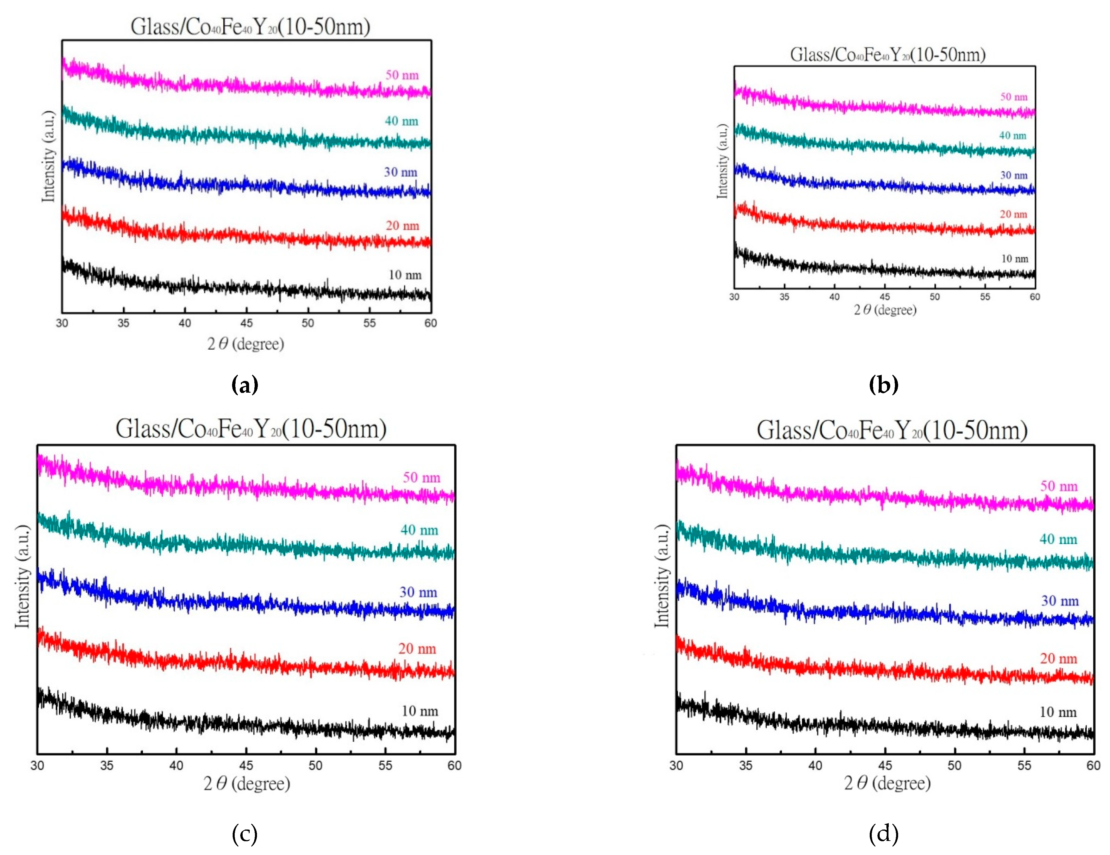
3.1. XRD, EDX, and AFM Morphology

As-deposited and annealed XRD patterns of various thicknesses are depicted in Figure 1. Figure 1a displays a peak plot of the as-deposited condition, and Figure 1b–d display a plot of the film after it has been annealed at corresponding temperatures of 100 °C, 200 °C, and 300 °C. The above figures show that the film structure is amorphous. According to the literature, the growth of alloyed films also reveals an amorphous state [35]. Furthermore, it is possible to draw the finding that grain development is not sufficiently supported by a thermal driving force [36,37].
The composition of the CoFeY films, as discovered by EDX analysis at 50 nm, is displayed in Table 3. However, due to material loss during the sputtering technique’s transport from the target to the substrate, the stoichiometry of the film and target may not be the same.
In order to calibrate the precise thicknesses, Figure 2 explores the corresponding thickness for the associated sputtering time. The linear relationship shown in this diagram suggests that thicker films are produced by longer sputtered times.
AFM was used to observe the degree of film coverage, which is shown in Figure 3a,b. From the result, the incomplete coverage of the 10 nm film and the full coverage of the 40 nm film can be shown by AFM. This result affects the significant properties. Figure 3c,d exhibit AFM profiles of 10 nm and 40 nm across the film edge, respectively.

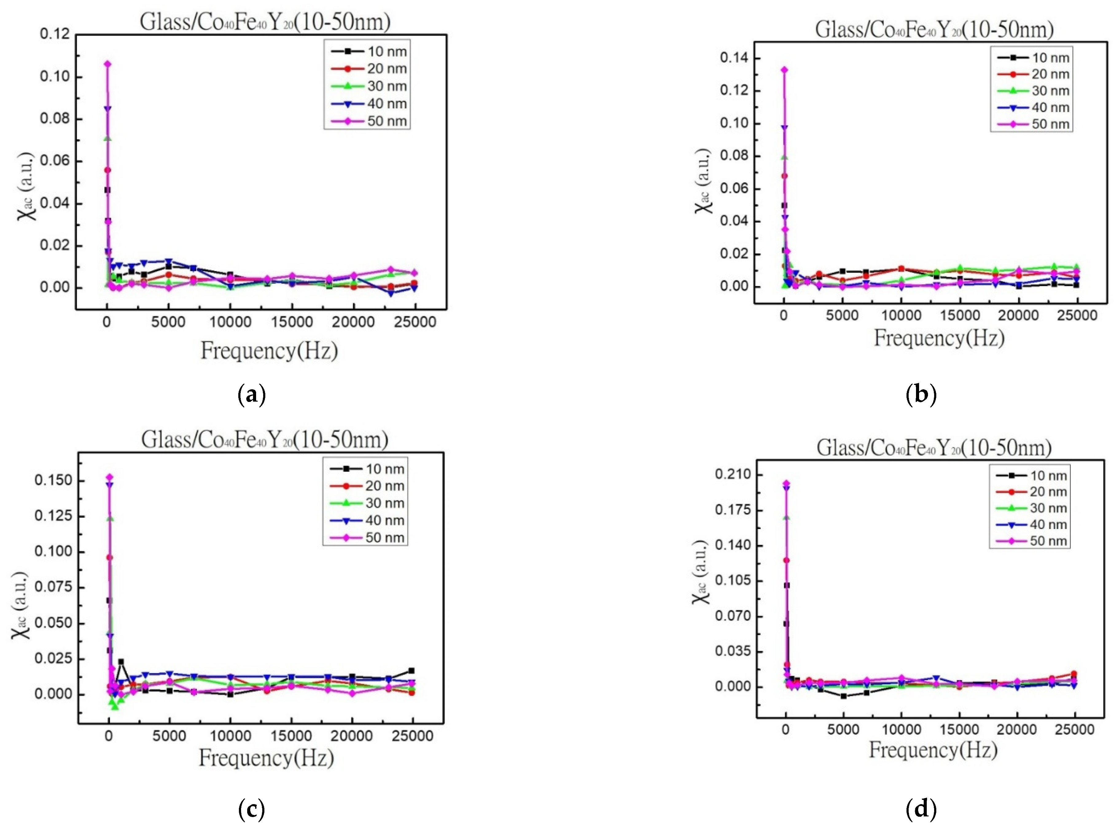
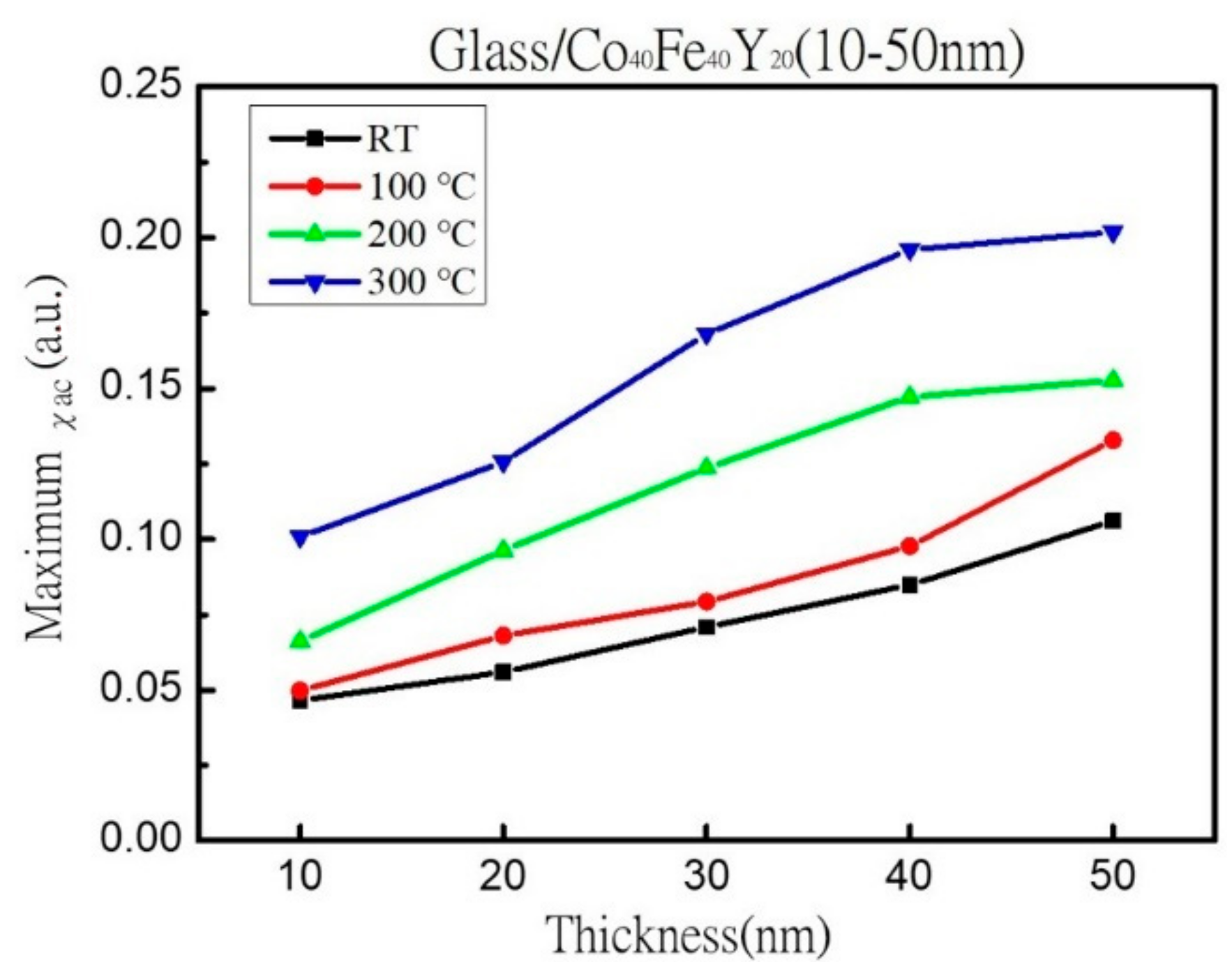
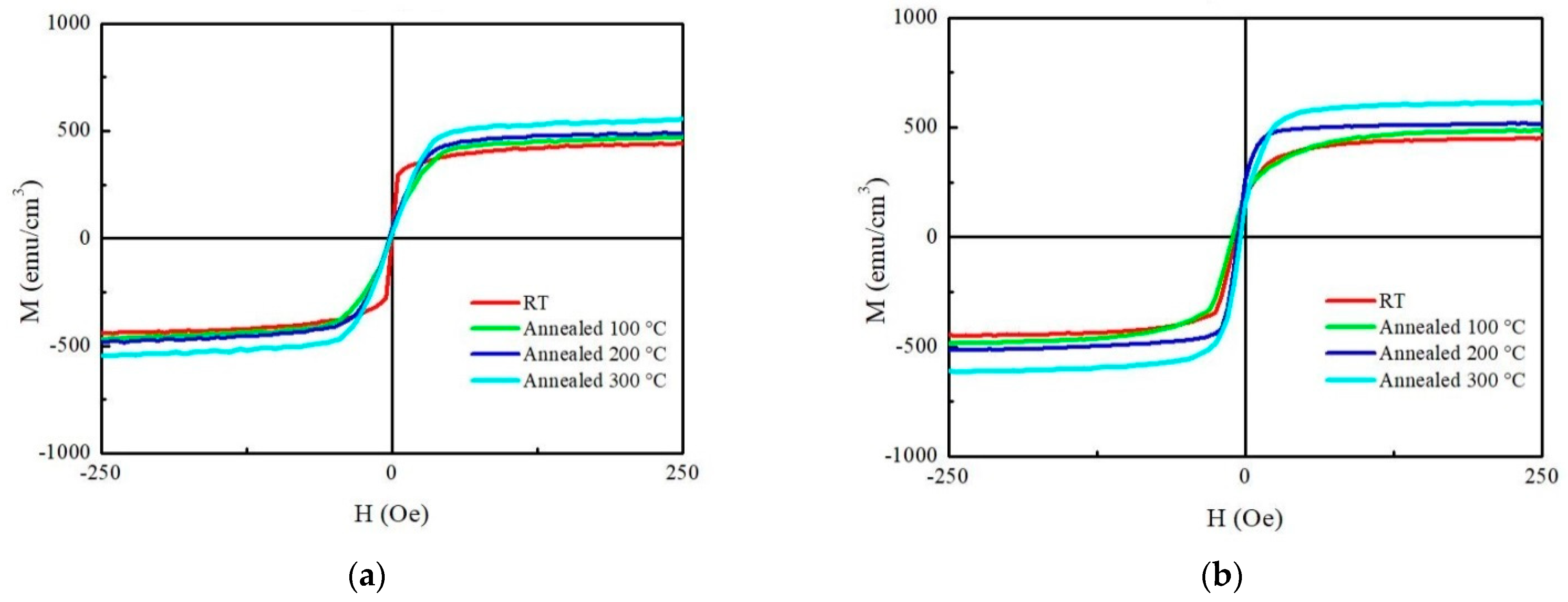
3.2. Magnetic Property

The χac is displayed in Figure 4a as a function of frequency from 50 Hz to 25,000 Hz for CoFeY films. The χac of the annealed CoFeY samples are shown in Figure 4b–d versus a frequency ranging from 50 Hz to 25,000 Hz. The average error of alternate-current magnetic susceptibility measurement was ±0.005. The result demonstrates that χac values declined as the measured frequency increased. The amplitude fell at high frequencies. Furthermore, because the glass substrate is diamagnetic, the negative signal in Figure 4c,d can be reasonably assumed to be the substrate signal or a small amount of noise. According to the result, the χac value should be near zero at a high frequency. After annealing, the alternate-current magnetic susceptibility changed by magnetic annealing anisotropy [38].
Figure 5 shows the corresponding maximum χac values for as-deposited and three annealing temperatures with different thicknesses. This study shows that when thickness and annealing temperatures increased, the maximum χac value increased as well. The results were obtained as a result of the thickness effect and Y addition, which increased the spin exchange coupling [39,40]. The thickness effect states that as the thickness increases, the maximum χac values also increase [41]. When the thickness was 50 nm, the maximum χac value was 0.11 at the as-deposited state, 0.13 when the annealed temperature was 100 °C, 0.15 when the heat treatment temperature was 200 °C, and the maximum χac value was 0.20 when the heat treatment temperature was 300 °C. To investigate the effect of Y addition, the maximum χac value of Co40Fe40Y20 film at 50 nm under the same four conditions is between 0.11 and 0.20, which is greater than the maximum χac value of the previously studied Co40Fe40Y10B10 film of 0.05 to 0.16, implying that the Y addition can enhance spin-exchange coupling and induce higher values [42]. The data thus show that CoFeY films have a thickness effect [43,44]. The ideal resonance frequency (fres) denotes the frequency at which the maximum χac has the greatest spin sensitivity. When the maximum χac value was supplied in addition to the fres value, the spin sensitivity improved considerably. The fact that the fres values of the thin films were in the low-frequency range of 50 to 100 Hz provides more proof that CoFeY magnetic thin films can be used in soft magnetic devices.
Hysteresis loops are shown in Figure 6a,b for 10 nm and 50 nm to study magnetization (M) by an in-plane external field (Hext) field of 250 Oe. According to the M-H results, the Ms value at 10 nm is between 440 emu/cm3 and 545 emu/cm3, while the Ms value at 50 nm is between 482 emu/cm3 and 610 emu/cm3. The Ms of the annealed treatment is greater than the Ms of the as-deposited state. It also shows that the lower Hc and higher Ms indicate that CoFeY film is a promising material as a free or pinned layer for MTJ applications. Therefore, this magnetic characteristic is compatible with the χac result. The modification of the shape of the hysteresis loop with an increase in the annealing temperature is seen due to magnetic anisotropy [45].

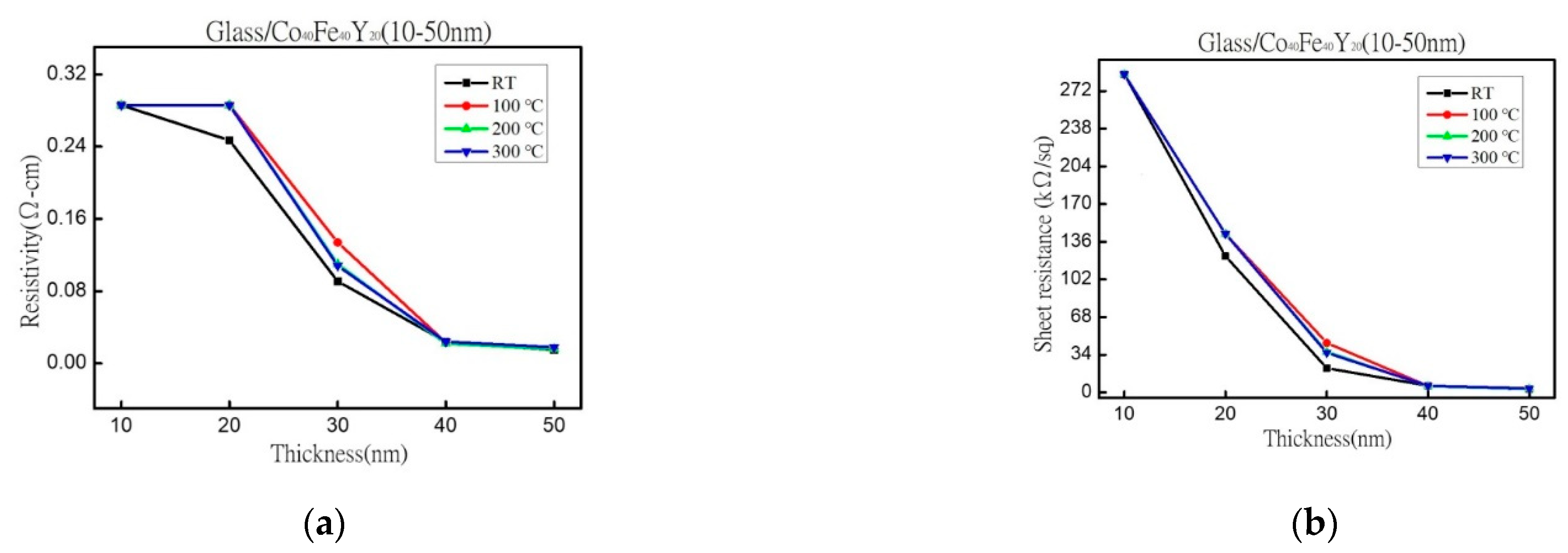
3.3. Electrical Properties

The resistivity of various thicknesses and at four conditions is depicted in Figure 7a. Figure 7b displays the sheet resistance for four different states and various thicknesses. When the film was thicker, the resistivity was smaller, and the amplitude of the resistance was closer to being flat. Because electron carriers are less constrained in their conduction, the electric resistivity and sheet resistance of thick film thickness and higher annealing temperatures are smaller than those of thinner thicknesses and lower annealing temperatures. The reason for the thinner film may be that it is not a continuous film throughout growth, which causes more barriers to electron transport and an increase in resistivity. It indicates that increasing the film thickness and fewer obstacles hinder the movement of electrons and increase electron conductivity [46,47]. For the 30 nm film, the resistivity is minimum at RT, and the resistivity is maximum for the 100 °C annealed film because the film is very thin, and it may be caused by the growth mode of the discontinuous film.

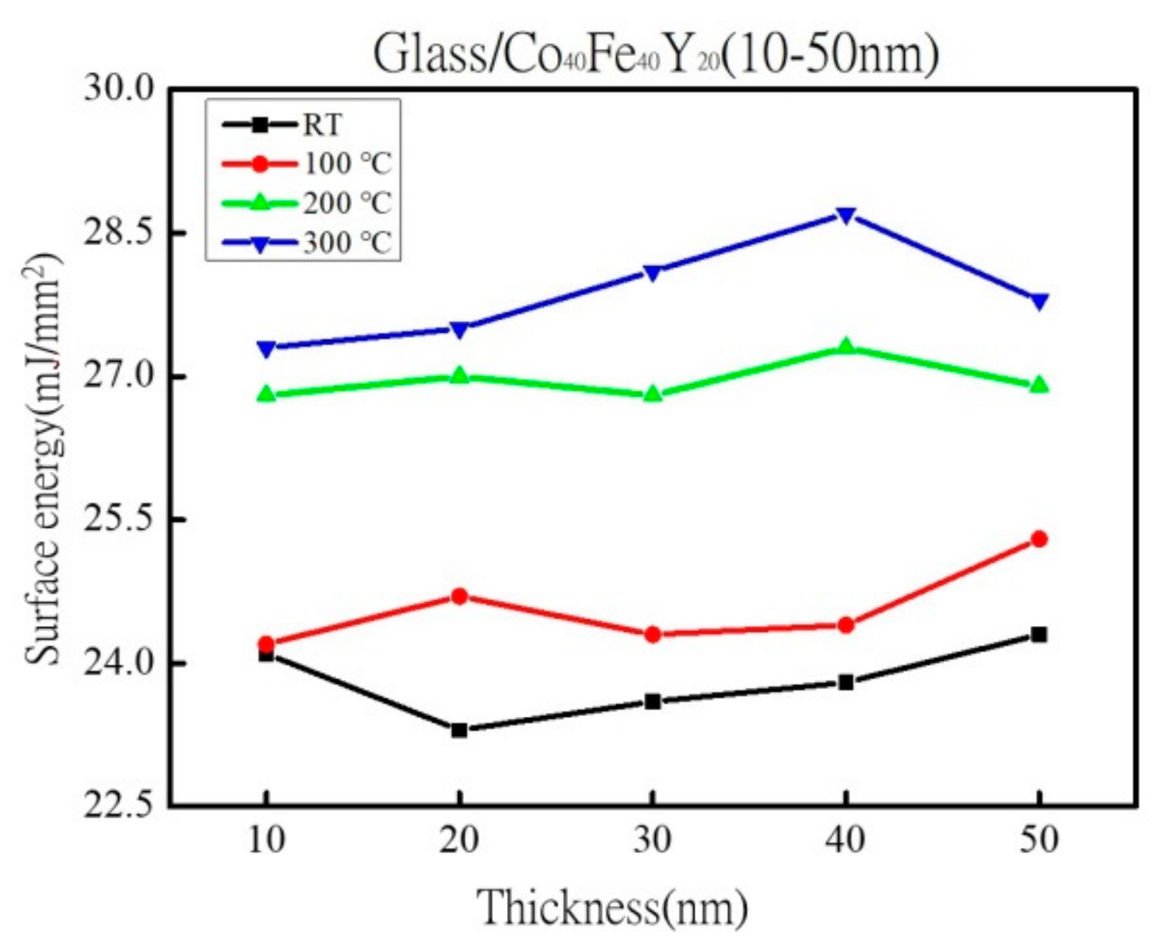
3.4. Analysis of Surface Energy and Adhesion

Figure 8 displays the surface energy for four distinct scenarios where the film thickness was raised from 10 nm to 50 nm. In comparison to the freshly as-deposited films, annealed films have a larger surface energy. The surface energy with the greatest value was 28.7 mJ/mm2 when the film was annealed at 300 °C with a thickness of 40 nm. It was found that the film adhered to surfaces with a greater force as the surface energy increased. Additionally, it was shown that the contact angle and surface energy have a close relationship. A greater liquid absorption area and a decrease in the contact angle occur when the surface free energy is high [48]. More liquid is also absorbed when the surface free energy is high. The contact angle and Young’s equation are used to derive the surface energy [29,30,31]. Low surface energy is correlated with weak adhesion [49]. The adhesion was strongest when the surface energy of the films was higher. These findings suggest that it is simpler to combine with the MTJ structure’s layer. The surface energy range of CoFeY films is from 23.3 mJ/mm2 to 28.7 mJ/mm2, which is more than fluorinated ethylene propylene copolymer (FEP) and equivalent to polystyrene (PS) [50].

3.5. Analysis of Optical Property

Table 4 displays the maximum and minimum transmittance in as-deposited and annealed states. It shows a decrease in minimum transmittance from 65.1% to 21.4% between the thicknesses of 10 and 50 nm. According to Table 4, the minimum transmittance dropped from 66.5% to 20.1% at an annealed temperature of 100 °C. At the 200 °C annealing temperature, it showed that the minimum transmittance dropped from 66.7% to 22.4%. Table 4 demonstrates that at the 300 °C annealing temperature, the minimum transmittance dropped from 70.7% to 20.8%. The annealing temperature was raised, but only a very slight change in transmittance was seen, and the trend was not immediately obvious. With increasing film thickness, the absorption strength of Co40Fe40Y20 films increased, but the transmittance decreased. This is due to a decrease in transmittance caused by the thickness effect, which mutes the optical signal [51]. It is assumed that when the thickness of most materials increases, the transmittance decreases. The film may hinder photons from passing through and reduce transmittance due to its thickness and high annealing temperature. The effect of annealing temperature on hydrophilicity and optical transmittance properties indicates that the contact angle results at the annealing temperature are smaller than that of the as-deposited film, which can be reasonably concluded that there is an increased continuous film mode after annealing. Moreover, the transmittance after annealing is slightly lower than RT, which means that continuous film occurs at a high annealing temperature, resulting in a slight decrease in the transmittance. Due to the state of the continuous film, the values of surface energy and magnetic characteristics are higher at a thick film thickness and higher annealing temperatures than they are at thinner thicknesses and lower annealing temperatures.

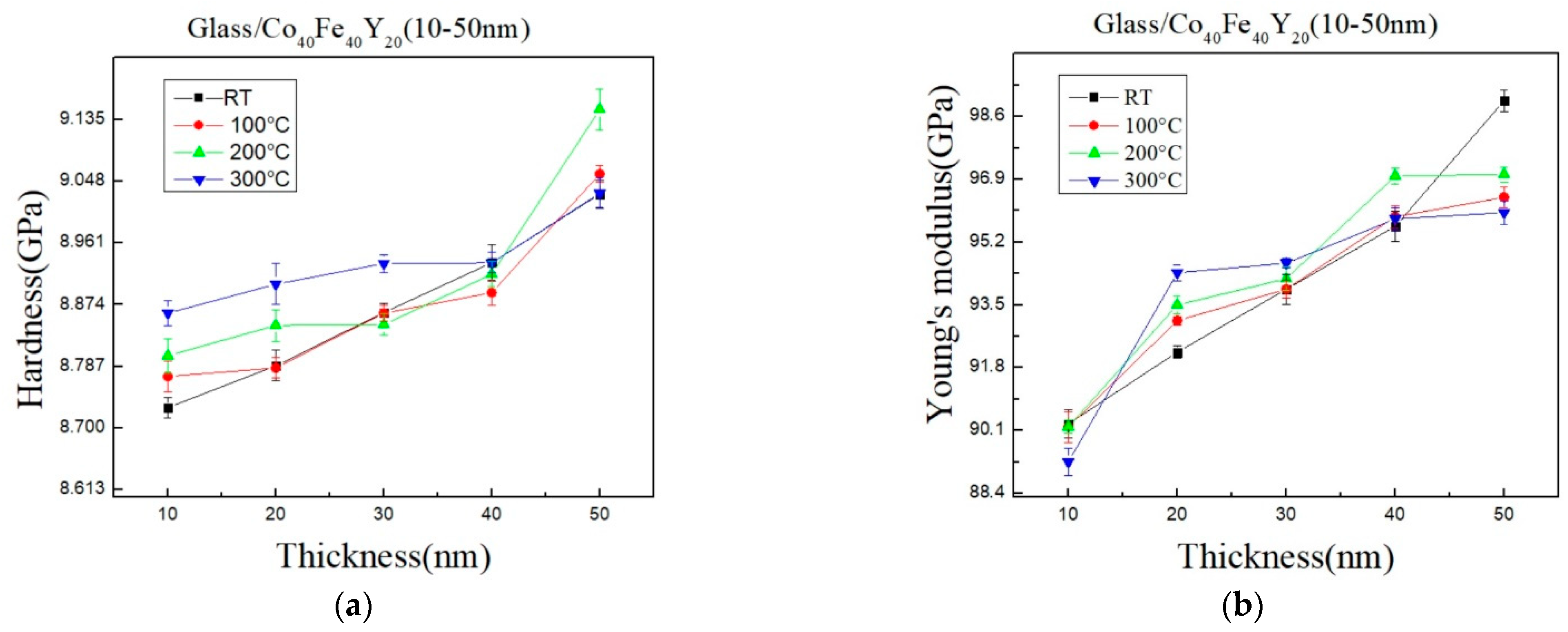
3.6. Hardness and Young’s Modulus

Figure 9a,b shows the hardness (H) and Young’s modulus (E) in their as-deposited and annealed states, respectively. When the thickness is increased, the hardness and Young’s modulus increase as a result. A nano-hardness indentation can be determined using the Pharr–Oliver method, which is based on the loading and unloading curve and exposes the combined hardness of the glass substrate and the CoFeY thin film [52]. Additionally, similar outcomes were also obtained with tungsten (W) films grown on glass and silicon substrates with an indentation displacement twice as great as the film thickness [53]. The substrate effects are significant even at shallow indentation depths. Given the thinness of the CoFeY thin film, it is reasonable to assume that the substrate will have an impact on the nanoindentation measurement. Furthermore, it can be found that the Young’s modulus maximum at RT and the hardness maximum at 200 °C because the initial pop-in displacement might be connected to the material’s yielding point [54]. However, it can be challenging to pinpoint the initial displacement burst since it may occur early in the loading process as a result of instrument error or surface roughness. At 200 °C for 1 h and 50 nm, the hardness achieves the maximum value, and further annealing reduces the hardness. The same behavior in terms of hardness was seen [55]. Generally, annealed films are harder than as-deposited films because annealing reduces free volume concentration, shortens the interatomic distance, and increases hardness [56,57]. According to the surface energy and hardness results, the films have changed after annealing due to atomic arrangement by thermal driving force [49].

4. Conclusions

In XRD, an amorphous state was identified due to insufficient thermal driving force and Y addition. According to the alternating current susceptibility experiment, the maximum χac value was obtained at 50 nm and annealed at 300 °C. The highest χac value of the Co40Fe40Y20 film increased following heat treatment. Due to the thickness effect and Y addition, the maximum χac value of each CoFeY film grew as film thickness increased, enhancing the spin exchange coupling. The fres means that the maximum χac has the highest spin sensitivity in the range of 50-100 Hz at all conditions. In comparison to thinner thicknesses and lower annealing temperatures, thick film thickness and higher annealing temperatures have lower electric resistivity and sheet resistance due to electron carrier movement. The surface energy increased as the heat treatment temperature increased. The maximum surface energy was obtained after annealing the 40 nm-thick film at 300 °C with a surface energy of 28.7 mJ/mm2. With increasing thickness, the hardness and Young’s modulus increase. The hardness reaches its maximum value after one hour at 200 °C and 50 nm, and subsequent annealing reduces the hardness. According to optical measurements, the transmittance decreases with increasing thickness. The resistivity and optical transmission also decrease with the increase in film thickness in this study.

Author Contributions

Conceptualization, W.-J.L., Y.-H.C., C.-C.C. and Y.-T.C.; Methodology, Y.-T.C., Y.-C.L. and Y.-J.H.; Validation, Formal Analysis, Y.-T.C. and P.-W.C.; Investigation, Y.-T.C. and W.-J.L.; Resources, Y.-T.C.; Writing—original draft preparation, Y.-T.C.; Writing—review and editing, Y.-T.C. and W.-J.L.; Supervision, Y.-T.C. and Y.-H.C.; Project Administration, C.-C.C. and Y.-T.C.; Funding Acquisition, W.-J.L., Y.-H.C. and C.-C.C. All authors have read and agreed to the published version of the manuscript.

Funding

This work was supported by the National Science and Technology Council, under Grant No. MOST 110-2221-E-992-054-MY3, MOST108-2221-E-224-015-MY3, MOST105-2112-M-224-001, and National Yunlin University of Science and Technology, under Grant No. 111T01.

Institutional Review Board Statement

Not applicable.

Informed Consent Statement

Not applicable.

Data Availability Statement

Not applicable.

Conflicts of Interest

The authors declare there are no conflict of interest regarding the publication of this paper. The funders had no role in the design of the study; in the collection, analyses, or interpretation of data; in the writing of the manuscript, or in the decision to publish the results.

References

  1. Scheunert, G.; Heinonen, O.; Hardeman, R.; Lapicki, A.; Gubbins, M.; Bowman, R.M. A review of high magnetic moment thin films for microscale and nanotechnology applications. Appl. Phys. Rev. 2016, 3, 011301. [Google Scholar] [CrossRef] [Green Version]
  2. Sunder, R.S.; Deevi, S. Soft magnetic FeCo alloys: Alloy development, processing, and properties. Int. Mater. Rev. 2005, 50, 157–192. [Google Scholar] [CrossRef]
  3. Ikeda, S.; Tagawa, I.; Uehara, Y.; Kubomiya, T.; Kane, J.; Kakehi, A.; Chikazawa, A. Write heads with pole tip consisting of high-Bs FeCoAlO films. IEEE Trans. Magn. 2002, 38, 2219–2221. [Google Scholar] [CrossRef]
  4. Cai, P.; Hong, Y.; Ci, S.; Wen, Z. In situ integration of CoFe alloy nanoparticles with nitrogen-doped carbon nanotubes as advanced bifunctional cathode catalysts for Zneair batteries. Nanoscale 2016, 8, 20048–20055. [Google Scholar] [CrossRef]
  5. Takenaka, K.; Saidoh, N.; Nishiyama, N.; Ishimaru, M.; Inoue, A. Novel soft-magnetic underlayer of a bit-patterned media using CoFe-based amorphous alloy thin film. Intermetallics 2012, 30, 100–103. [Google Scholar] [CrossRef]
  6. Rahaman, M.; Ruban, A.V.; Mookerjee, A.; Johansson, B. Magnetic state effect upon the order-disorder phase transition in Fe-Co alloys: A first-principles study. Phys. Rev. B 2011, 83, 054202. [Google Scholar] [CrossRef]
  7. Gould, H.L.B.; Wenny, D.H. Supermendur: A new rectangular-loop magnetic material. Electr. Eng. 1957, 76, 208–211. [Google Scholar] [CrossRef]
  8. Sakita, A.; Passamani, E.; Kumar, H.; Cornejo, D.; Fugivara, C.; Noce, R.; Benedetti, A. Influence of current density on crystalline structure and magnetic properties of electrodeposited Co-rich CoNiW alloys. Mater. Chem. Phys. 2013, 141, 576–581. [Google Scholar] [CrossRef]
  9. Kogachi, M.; Tadachi, N.; Kohata, H.; Ishibashi, H. Magnetism and point defect in B2-type CoFe alloys. Intermetallics 2005, 13, 535–542. [Google Scholar] [CrossRef]
  10. Chen, Y.; Jen, S.; Yao, Y.; Wu, J.; Hwang, G.; Tsai, T.; Chang, Y.; Sun, A. Magnetic, structural and electrical properties of ordered and disordered Co50Fe50 films. J. Magn. Magn. Mater. 2006, 304, e71–e74. [Google Scholar] [CrossRef]
  11. Kockar, H.; Ozergin, E.; Karaagac, O.; Alper, M. Characterisations of CoFeCu films: Influence of Fe concentration. J. Alloys Compd. 2014, 586, S326–S330. [Google Scholar] [CrossRef]
  12. Mihajlovic, J.; Rinklebe, J. Rare earth elements in German soils—A review. Chemosphere 2018, 205, 514–523. [Google Scholar] [CrossRef]
  13. Li, D.-Q.; Zhou, L.-X.; Zhu, K.-J.; Gu, J.; Zheng, S.-H. Isothermal oxidation behavior of scandium and yttrium co-doped B2-type iron–aluminum intermetallics at elevated temperature. Rare Met. 2018, 37, 690–698. [Google Scholar] [CrossRef]
  14. Liu, J.; Wu, Q.; Yan, H.; Zhong, S.; Huang, Z. Effect of Trace Yttrium Addition and Heat Treatmenton the Microstructure and Mechanical Properties of As-Cast ADC12 Aluminum Alloy. Appl. Sci. 2019, 9, 53. [Google Scholar] [CrossRef] [Green Version]
  15. Baulin, O.; Bugnet, M.; Fabrègue, D.; Lenain, A.; Gravier, S.; Cazottes, S.; Kapelski, G.; Ovanessian, B.T.; Balvay, S.; Hartmann, D.J.; et al. Improvement of mechanical, thermal, and corrosion properties of Ni- and Al-free Cu–Zr–Ti metallic glass with yttrium addition. Materialia 2018, 1, 249–257. [Google Scholar] [CrossRef]
  16. Liu, Z.; Qian, D.; Zhao, L.; Zheng, Z.; Gao, X.; Ramanujan, R. Enhancing the coercivity, thermal stability and exchange coupling of nano-composite (Nd,Dy,Y)–Fe–B alloys with reduced Dy content by Zr addition. J. Alloys Compd. 2014, 606, 44–49. [Google Scholar] [CrossRef]
  17. Liu, Z.; Qian, D.; Zeng, D. Reducing Dy Content by Y Substitution in Nanocomposite NdFeB Alloys With Enhanced Magnetic Properties and Thermal Stability. IEEE Trans. Magn. 2012, 48, 2797–2799. [Google Scholar] [CrossRef]
  18. Zhang, C.H.; Luo, Y.; Yu, D.B.; Quan, N.T.; Wu, G.Y.; Dou, Y.K.; Hu, Z.; Wang, Z.L. Permanent magnetic properties of Nd–Fe–B melt-spun ribbons with Y substitution. Rare Metals 2020, 39, 55–61. [Google Scholar] [CrossRef]
  19. Courcot, E.; Rebillat, F.; Teyssandier, F.; Louchet-Pouillerie, C. Stability of rare earth oxides in a moist environment at elevated temperatures—Experimental and thermodynamic studies: Part II: Comparison of the rare earth oxides. J. Eur. Ceram. Soc. 2010, 30, 1911–1917. [Google Scholar] [CrossRef]
  20. Aghazadeh, M.; Barmi, A.-A.M.; Shiri, H.M. Cathodic electrodeposition and characterization of nanostructured Y2O3 from chloride solution Part I: Effect of current density. Russ. J. Electrochem. 2013, 49, 344–353. [Google Scholar] [CrossRef]
  21. Yan, F.; Liu, Z.T.; Liu, W.T. The preparation and properties of Y2O3/AlN anti-reflection films on chemical vapor deposition diamond. Thin Solid Films 2011, 520, 734–738. [Google Scholar] [CrossRef]
  22. Pearce, S.J.; Parker, G.J.; Charlton, M.D.B.; Wilkinson, J.S. Structural and optical properties of yttrium oxide thin films for planar wave guiding application. J. Vac. Sci. Technol. A 2010, 28, 1388–1392. [Google Scholar] [CrossRef] [Green Version]
  23. Liu, W.J.; Ou, S.L.; Chang, Y.H.; Chen, Y.T.; Chiang, M.R.; Hsu, S.C.; Chu, C.L. Adhesive characteristic, surface mor-phology, and optical properties of Co40Fe40V20 films. Opt.-Int. J. Light Electron Opt. 2020, 216, 164587. [Google Scholar] [CrossRef]
  24. Liu, W.J.; Chen, Y.T.; Chang, Y.H.; Chiang, M.R.; Li, W.H.; Tseng, J.Y.; Chi, P.W.; Wu, T.H. Structure and magnetic properties of Co40Fe40V20 Thin Films. J. Nanosci. Nanotechnol. 2019, 19, 5974–5978. [Google Scholar] [CrossRef] [PubMed]
  25. Liu, W.J.; Chang, Y.H.; Ou, S.L.; Chen, Y.T.; Li, W.H.; Jhou, T.Y.; Chu, C.C.; Wu, T.H.; Tseng, S.W. Effect of annealing on the structural, magnetic, surface energy and optical properties of Co32Fe30W38 films deposited by direct-current magnetron sputtering. Coatings 2020, 10, 1028. [Google Scholar] [CrossRef]
  26. Liu, W.J.; Chang, Y.H.; Chiang, C.C.; Chen, Y.T.; Chen, Y.S.; Liao, H.W.; Wu, T.H.; Lin, S.H.; Chi, P.W. Effect of annealing and thickness of Co40Fe40Yb20 thinfilms on various physical properties on a glass substrate. Materials 2022, 15, 8509. [Google Scholar] [CrossRef]
  27. Liu, W.-J.; Chang, Y.-H.; Chiang, C.-C.; Chen, Y.-T.; Liu, Y.-C.; Ou, S.-L.; Li, S.-Y.; Chi, P.-W. Co40Fe40Y20 Nanofilms’ Structural, Magnetic, Electrical, and Nanomechanical Characteristics as a Function of Annealing Temperature and Thickness. Coatings 2023, 13, 137. [Google Scholar] [CrossRef]
  28. Rankl, M.; Laib, S.; Seeger, S. Surface tension properties of surface-coatings for application in biodiagnostics determined by contact angle measurements. Colloids Surf. B Biointerfaces 2003, 30, 177–186. [Google Scholar] [CrossRef]
  29. Park, C.; Zhu, J.-G.; Moneck, M.T.; Peng, Y.; Laughlin, D.E. Annealing effects on structural and transport properties of rf-sputtered CoFeB/MgO/CoFeB magnetic tunnel junctions. J. Appl. Phys. 2006, 99, 08A901. [Google Scholar] [CrossRef] [Green Version]
  30. Yamamoto, M.; Marukame, T.; Ishikawa, T.; Matsuda, K.; Uemura, T.; Arita, M. Fabrication of fully epitaxial magnetic tunnel junctions using cobalt-based full-Heusler alloy thin film and their tunnel magnetoresistance characteristics. J. Phys. D Appl. Phys. 2006, 39, 824–833. [Google Scholar] [CrossRef]
  31. Suchaneck, G.; Artiukh, E.; Sobolev, N.A.; Telesh, E.; Kalanda, N.; Kiselev, D.A.; Ilina, T.S.; Gerlach, G. Strontium Ferro-molybdate-Based Magnetic Tunnel Junctions. Appl. Sci. 2022, 12, 2717. [Google Scholar] [CrossRef]
  32. Ma, K.; Chung, T.S.; Good, R.J. Surface energy of thermotropic liquid crystalline polyesters and polyesteramide. J. Polym. Sci. 1998, 36, 2327–2337. [Google Scholar] [CrossRef]
  33. Owens, D.K.; Wendt, R.C. Estimation of the surface free energy of polymers. J. Appl. Polym. Sci. 1969, 13, 1741–1747. [Google Scholar] [CrossRef]
  34. Kaelble, D.H.; Uy, K.C. A Reinterpretation of Organic Liquid-Polytetrafluoroethylene Surface Interactions. J. Adhes. 1970, 2, 50–60. [Google Scholar] [CrossRef]
  35. Chen, Q.; Zhang, D.; Shen, J.; Fan, H.; Sun, J. Effect of yttrium on the glass-forming ability of Fe-Cr-Mo-C-B bulk amorphous alloys. J. Alloys Compd. 2007, 427, 190–193. [Google Scholar] [CrossRef]
  36. Kube, S.A.; Xing, W.; Kalidindi, A.; Sohn, S.; Datye, A.; Amram, D.; Schuh, C.A.; Schroers, J. Combinatorial study of thermal stability in ternary nanocrystalline alloys. Acta Mater. 2020, 188, 40–48. [Google Scholar] [CrossRef]
  37. Peng, H.; Huang, L.; Liu, F. A thermo-kinetic correlation for grain growth in nanocrystalline alloys. Mater. Lett. 2018, 219, 276–279. [Google Scholar] [CrossRef]
  38. Luborsky, F.; Walter, J. Magnetic anneal anisotropy in amorphous alloys. IEEE Trans. Magn. 1977, 13, 953–956. [Google Scholar] [CrossRef]
  39. Chen, Z.; Luo, J.; Sui, Y.; Guo, Z. Effect of yttrium substitution on magnetic properties and microstructure of Nd-Y-Fe-B nanocomposite magnets. J. Rare Earths 2010, 28, 277–281. [Google Scholar] [CrossRef]
  40. Liao, X.; Zhang, J.; Li, W.; Khan, A.J.; Yu, H.; Zhong, X.; Liu, Z. Performance improvement and element segregation behavior in Y substituted nanocrystalline (La,Ce)–Fe–B permanent magnetic alloys without critical RE elements. J. Alloys Compd. 2020, 834, 155226. [Google Scholar] [CrossRef]
  41. Kim, Y.M.; Han, S.H.; Kim, H.J.; Choi, D.; Kim, K.H.; Kim, J. Thickness effects on magnetic properties and ferromagnetic resonance in Co–Ni–Fe–N soft magnetic thin films. J. Appl. Phys. 2002, 91, 8462–8464. [Google Scholar] [CrossRef]
  42. Liu, W.-J.; Chang, Y.-H.; Chen, Y.-T.; Chiang, Y.-C.; Tsai, D.-Y.; Wu, T.-H.; Chi, P.-W. Effect of Annealing on the Characteristics of CoFeBY Thin Films. Coatings 2021, 11, 250. [Google Scholar] [CrossRef]
  43. Kumari, T.P.; Raja, M.M.; Kumar, A.; Srinath, S.; Kamat, S. Effect of thickness on structure, microstructure, residual stress and soft magnetic properties of DC sputtered Fe65Co35 soft magnetic thin films. J. Magn. Magn. Mater. 2014, 365, 93–99. [Google Scholar] [CrossRef]
  44. Almasi-Kashi, M.; Ramazani, A.; Kheyri, F.; Jafari-Khamse, E. The effect of magnetic layer thickness on magnetic properties of Fe/Cu multilayer nanowires. Mater. Chem. Phys. 2014, 144, 230–234. [Google Scholar] [CrossRef]
  45. Kumar, L.; Kar, M. Effect of Annealing Temperature and Preparation Condition on Magnetic Anisotropy in Nanocrystalline Cobalt Ferrite. IEEE Trans. Magn. 2011, 47, 3645–3648. [Google Scholar] [CrossRef]
  46. Jen, S.U.; Yao, Y.D.; Chen, Y.T.; Wu, J.M.; Lee, C.C.; Tsai, T.L.; Chang, Y.C. Magnetic and electrical properties of amorphous CoFeB films. J. Appl. Phys. 2006, 99, 053701. [Google Scholar] [CrossRef] [Green Version]
  47. Wang, C.M.; Hsieh, J.H.; Li, C. Electrical and piezoresistive properties of TaN-Cu nanocomposite thin films. Thin Solid Films 2004, 469–470, 455–459. [Google Scholar] [CrossRef]
  48. Kong, S.H.; Okamoto, T.; Nakagawa, S. [Ni-Fe/Si] double seedlayer with low surface energy for Fe-Co-B soft magnetic underlayer with high Hk for perpendicular magnetic recording media. IEEE Trans. Magn. 2004, 40, 2389–2391. [Google Scholar] [CrossRef]
  49. Porter, D.A.; Easterling, K.E. Phase Transformations in Metals and Alloy, 2nd ed.; CRC Press: London, UK, 1992. [Google Scholar]
  50. Absolom, D.; Eom, K.; Vargha-Butler, E.; Hamza, H.; Neumann, A. Surface properties of coal particles in aqueous media II. Adhesion of coal particles to polymeric substrates. Colloids Surf. 1986, 17, 143–157. [Google Scholar] [CrossRef]
  51. Kapustianyk, V.; Turko, B.; Kostruba, A.; Sofiani, Z.; Derkowska, B.; Dabos-Seignon, S.; Barwiński, B.; Eliyashevskyi, Y.; Sahraoui, B. Influence of size effect and sputtering conditions on the crystallinity and optical properties of ZnO thin films. Opt. Commun. 2007, 269, 346–350. [Google Scholar] [CrossRef]
  52. Oliver, W.C.; Pharr, G.M. An improved technique for determining hardness and elastic modulus using load and dis-placement sensing indentation experiments. J. Mater. Res. 1992, 7, 1564–1583. [Google Scholar] [CrossRef]
  53. Chen, S.; Liu, L.; Wang, T. Investigation of the mechanical properties of thin films by nanoindentation, considering the effects of thickness and different coating–substrate combinations. Surf. Coat. Technol. 2005, 191, 25–32. [Google Scholar] [CrossRef]
  54. Lashgari, H.; Cadogan, J.; Chu, D.; Li, S. The effect of heat treatment and cyclic loading on nanoindentation behaviour of FeSiB amorphous alloy. Mater. Des. 2016, 92, 919–931. [Google Scholar] [CrossRef]
  55. Sun, Y.; Song, M.; Liao, X.; Sha, G.; He, Y. Effects of isothermal annealing on the microstructures and mechanical properties of a FeCuSiBAl amorphous alloy. Mater. Sci. Eng. A 2012, 543, 145–151. [Google Scholar] [CrossRef]
  56. Gu, J.; Song, M.; Ni, S.; Guo, S.; He, Y. Effects of annealing on the hardness and elastic modulus of a Cu36Zr48Al8Ag8 bulk metallic glass. Mater. Des. 2013, 47, 706–710. [Google Scholar] [CrossRef]
  57. Turnbull, D.; Cohen, M.H. On the free volume model of liquid glass transition. J. Chem. Phys. 1970, 52, 3038–3041. [Google Scholar] [CrossRef]
Figure 1. XRD patterns. (a) RT, (b) after annealing at 100 °C, (c) after annealing at 200 °C, (d) after annealing at 300 °C.
Materials 16 02490 g001
Figure 2. The corresponding thickness of associated sputtered time.
Materials 16 02490 g002
Figure 3. AFM surface morphology at RT at (a) 10 nm and (b) 40 nm. AFM profiles across the film edge at (c) 10 nm and (d) 40 nm.
Materials 16 02490 g003
Figure 4. χac result as a function of the frequency from 50 to 25,000 Hz. (a) RT, (b) after annealing at 100 °C, (c) after annealing at 200 °C, (d) after annealing at 300 °C.
Materials 16 02490 g004
Figure 5. Maximum χac.
Materials 16 02490 g005
Figure 6. M-H loop of CoFeY films under four conditions; (a) 10 nm and (b) 50 nm.
Materials 16 02490 g006
Figure 7. (a) The resistivity. (b) The sheet resistance.
Materials 16 02490 g007
Figure 8. The surface energy under four conditions.
Materials 16 02490 g008
Figure 9. Nano-indentation of CoFeY thin films. (a) Hardness and (b) Young’s modulus.
Materials 16 02490 g009
Table 1. Names of proper nouns in full and abbreviated form.
AbbreviationFull Name
CoFeYCobalt Iron Yttrium
YYttrium
XRDX-ray diffraction
χacLow-frequency alternate-current magnetic susceptibility
MsSaturation magnetization
HcCoercivity
CoFeCobalt Iron
MRAMMagnetic random-access memory
RERare earth
Y2O3Yttrium oxide
Co40Fe40B20Cobalt Iron Boron
MTJMagnetic tunneling junction
RTRoom temperature
CoFeVCobalt Iron Vanadium
CoFeWCobalt Iron Tungsten
CoFeYbCobalt Iron Ytterbium
DCDirect current
TAAnnealed temperature
ArArgon
GIXRDGrazing incidence X-ray diffraction
EDXEnergy dispersive X-ray spectroscopy
AFMAtomic force microscopy
a.u.Arbitrary unit
ƒresOptimal resonance frequency
VSMVibrating sample magnetometer
θContact angle
DIDeionized
CSMContinuous stiffness measurement
MMagnetization
HextExternal field
FEPFluorinated ethylene propylene copolymer
PSPolystyrene
WTungsten
HHardness
EYoung’s modulus
Table 2. Significant properties for CoFeV, CoFeW, and CoFeYb materials.
MaterialsMaximum χac
(a.u.)
Surface Energy (mJ/mm2)Transmittance (%)
Glass substrate/Co40Fe40V20 [23,24]
10–100 nm at RT
0.02–0.0427.8–45.4x
Glass substrate/Co32Fe30W38 [25]
10-50 nm at RT and annealed conditions
0.02–0.5222.3–28.4x
Glass substrate/Co40Fe40Yb20 [26]
10–50 nm at RT and annealed conditions
0.04–0.3528.6–34.522.3–80.5
Si(100) substrate/Co40Fe40Y20 [27]
10–50 nm at RT and annealed conditions
0.03–0.1622.7–31.1x
Glass substrate/Co40Fe40Y20
10–50 nm at RT and annealed conditions
(Current research)
0.04–0.2023.3–28.720.1–81.7
Table 3. EDX analysis data for alloy films.
ElementWeight%Atomic%
Fe 28.0636.56
Co 38.1247.07
Y 33.8216.37
Totals100.00
Table 4. Transmittance for Co40Fe40Y20 thin films.
ProcessThicknessMinimum Transmittance (%)Maximum Transmittance (%)
As-deposited10 nm65.181.7
20 nm62.378.8
30 nm34.341.4
40 nm23.234.5
50 nm21.432.5
Annealing 100 °C10 nm66.578.6
20 nm58.774.6
30 nm39.142.3
40 nm24.231.2
50 nm20.129.4
Annealing 200 °C10 nm66.780.5
20 nm61.172.2
30 nm38.241.2
40 nm25.130.8
50 nm22.429.5
Annealing 300 °C10 nm70.778.4
20 nm60.166.6
30 nm31.136.1
40 nm22.429.1
50 nm20.828.2
Disclaimer/Publisher’s Note: The statements, opinions and data contained in all publications are solely those of the individual author(s) and contributor(s) and not of MDPI and/or the editor(s). MDPI and/or the editor(s) disclaim responsibility for any injury to people or property resulting from any ideas, methods, instructions or products referred to in the content.

