1. Introduction
In mining, a large amount of energy loss results from friction and wear of working elements. It is estimated that 38% of the energy consumed in mines is related to friction. Friction also affects the efficiency of the entire mining process. Longwall shearers are an example of a device where friction is a significant factor of wear. The wear may concern the teeth of the drive wheel itself, as well as other elements, e.g., the entire haulage system of a longwall shearer [
1]. Eicotrack is a haulage system very often used in mines, although it is not adapted to modern requirements. Since the 90s of the last century, longwall shearer have been equipped with automated systems increasing safety and mining capacity. As a result, the shearers’ development is, among others, an increase in their pulling force. In connection with the rigid structure of the haulage system, this increases the tribological wear. In this case, wear can cause breakdowns, downtime and losses during mining works [
2,
3].
The specific working conditions of the haulage system toothed segments in cooperation with the wheel of the longwall shearer give an extra requirement for the materials used. Alloys intended for the production of these parts should cut the degree of wear of the shearer’s longwall drive wheel [
4].
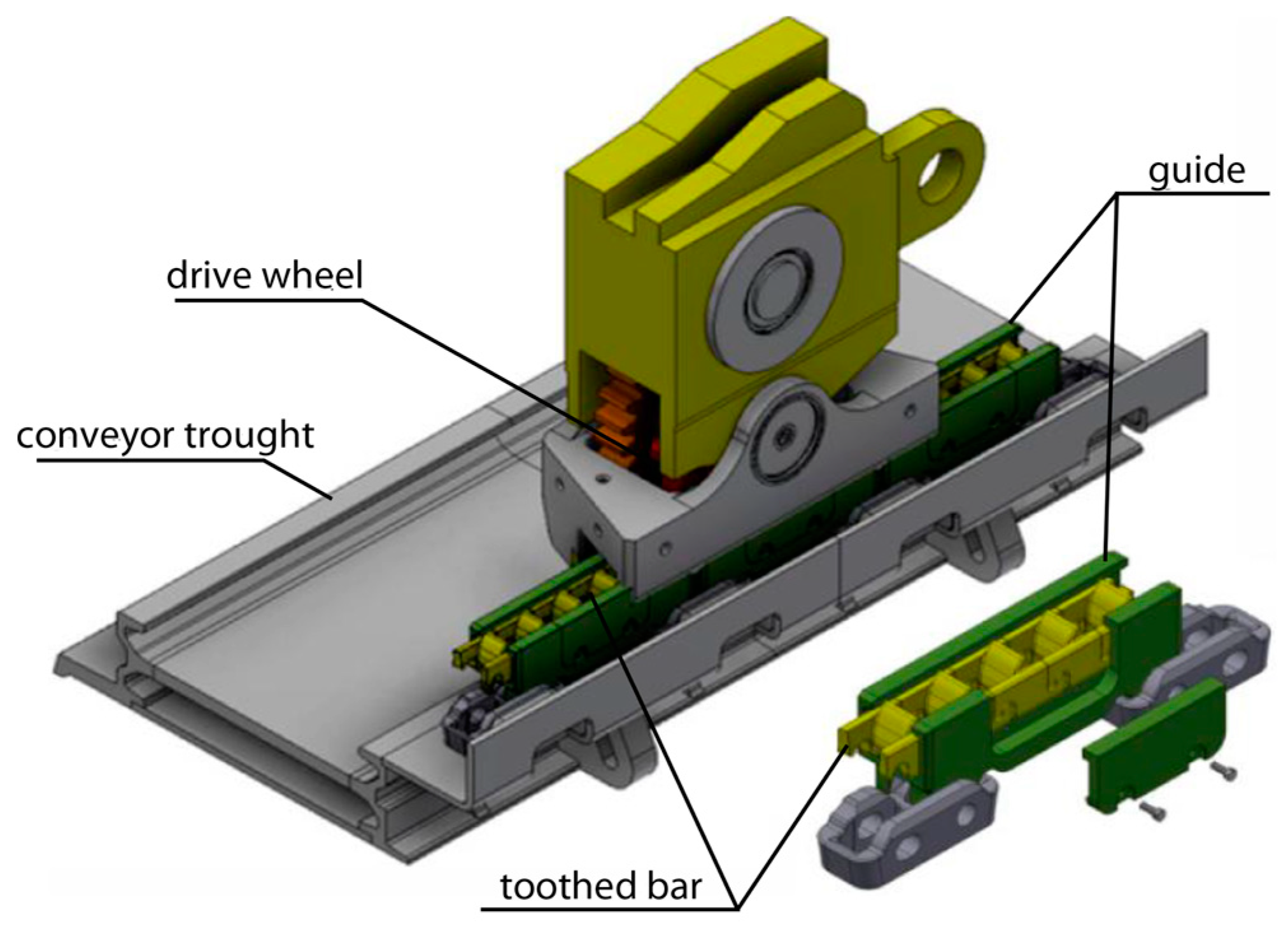
Figure 1 shows the method of cooperation between the wheel and the newly developed haulage system. On the conveyor through there are guide elements in which individual toothed bar segments are placed. The drive wheel cooperates with these segments, causing the movement of the shearer. Replacing this wheel during mining processes is complicated. This operation is a time-consuming operation that causes significant production downtime. One of the ways to increase service life and safety is by changing the design. Another way is the appropriate change of the materials used. These solutions are proven paths in the mining industry [
5]. The material used for the drive wheels of the longwall shearer is carburized nickel-chromium steel 20H2N4A. This grade of steel is designed to work with heavy loads. It can be carburized and subjected to heat treatment, which consists of quenching and tempering. After this process, a carburized surface with a hardness close to 60 HRC is obtained. The carburized layer can reach a few millimeters deep into the material, depending on the method used and the parameters of the heat treatment process. The layer is resistant to wear and rolling contact fatigue. Although many modern materials have appeared, this grade still remains competitive [
6,
7,
8]. During the longwall shearer work, wheel and toothed segments cooperate with each other. These elements constitute a friction pair in the operation process. It seems that hardness may be one of the parameters of the choice of materials intended for rack segment production. The hardness of a material is an important factor in proving its resistance to wear. However, hardness does not have to be the decisive factor. One of the most important goals of the work carried out is to get the possible lowest wear of the drive wheel together with the longest service life of the toothed segments [
9,
10,
11].
Due to the characteristics of the deposit, the direction of the path of the conveyor troughs is not straight, and it can bend both vertically and horizontally. This affects the haulage system, and in conjunction with the rigid attachment of some elements (e.g., toothed bars) of this system, the position of the shearer’s drive wheel relative to the axis of the tooth segments may change. In the case of changes in the direction of the track in the vertical plane, the permissible contact stresses may be significantly exceeded. They may show so-called tooth edges, which significantly accelerate the process of wheel wear. Another mechanism occurring in the process of wear of the friction pair between the drive wheel and the tooth segments is slip. The mentioned mechanisms accelerate the process of wear of the wheel and toothed segments, necessitating the replacement of the drive wheel. These effects can be minimized by changing the design elements of the haulage system. On the other hand, focusing on specific parameters, e.g., by reducing contact stresses, may cause more intensive wear of wheels and toothed segments compared to the old design. Regardless of the design of the haulage system, as in each friction pair, various wear mechanisms may occur [
12,
13,
14,
15].
Figure 1.
Haulage system 3D model [
13].
Figure 1.
Haulage system 3D model [
13].
In coal mining, machinery and equipment are exposed to aggressive environments and loads. Working surfaces can wear due to various wear mechanisms. One of the most common wear mechanisms in mining is abrasion, and a combination of plastic deformation, abrasion and oxidative wear can also be encountered. Other wear mechanisms that can occur in mining are adhesive wear and fatigue. In a friction pair, the wear mechanisms may depend on several conditions, one of which is the type of cooperating materials [
16,
17,
18].
Austempered ductile iron (ADI) has good mechanical properties and wear resistance. In ADI, the wear resistance of the surface layer can be increased by a transformation of the austenite into martensite. The transformation process is possible under load [
19,
20]. The second group of analyzed alloys was several grades of cast steel, including high manganese cast steel which ensures high resistance to abrasive wear. These alloys have many applications in cement plants, transport and mining, for example, a roller ore crusher. Hadfield cast steel with an Mn content of 10–14% is used there due to the well-known excellent abrasive resistance. A number of phenomena, such as twin-twin hardening, dislocation hardening, and dynamic strain gain, among others, influence this property. At the same time, these alloys show good mechanical and plastic properties [
21,
22]. Other tested cast steel grades contained elements such as Cr, Ni, Mo, and V in their chemical composition. Some of these elements contribute to the formation of carbides which play an important role in the wear process. The heat treatment also affects the obtained microstructure and, thus, the properties [
9,
23]. This heat treatment consists of quenching and tempering (Q&T), a process that is often used in the production of steel-cast components. In the quenching process, alloying elements might be required if the martensitic structure is to be obtained in the entire volume in a diffusionless transition process. After the quenching process, the microstructure of cast steel gives high hardness and strength, but, at the same time, low plasticity and fracture resistance are achieved due to hardening stresses and high dislocation density. Performing a tempering procedure can change this. When the tempering temperature does not exceed 250 °C, the α’ phase or the carbon supersaturated solution is transformed into tempered martensite α’’ due to carbon diffusion and precipitation of Fe
2C–Fe
2,4C type carbides, or Fe
3C if the tempering temperature is higher. During the tempering process, bainite may also be formed as a result of the transformation of the residual austenite [
24,
25]. The final properties of toughened steels depend on the microstructure that evolves during the Q&T process. In the design of the heat treatment process, we can use computer analysis. However, in practice, the Q&T process is often designed using empirical methods. Even in this case, differences in both the alloy composition and the geometry may result in a much lower ability to predict the properties of the designed part [
26]. After the Q&T process, a mixed structure may be obtained, which consists of martensite, residual austenite, bainite and perlite. This list does not exhaust all the components of the structure that can be obtained in the Q&T process in a steel casting. This list is presented in descending order due to the wear resistance. The relationship between microstructure and wear resistance has not been fully explained so far. It is generally accepted that the main factors influencing the wear of martensitic steels are hardness and ductility. Li also draws attention to carbides and their morphology. One of the conclusions obtained by Trevisiol is the influence on the wear resistance of factors such as the morphology of martensite or the two-phase structure of the alloy [
27,
28,
29,
30,
31].
The literature review of longwall shearer haulage systems focuses mainly on the drive system modeling, and there is much less information about the tribological properties of the friction pairs of materials used in cooperating elements. There is not enough data in the literature describing alloy the work of the entire friction pair where the carburized steel for drive wheel longwall shearer is one of the materials [
32,
33,
34].
2. Materials and Methods
2.1. Materials
The samples of chosen grades of cast steel and ADI cast iron were taken from cast ingots obtained from melts conducted in an open induction furnace in a crucible with a capacity of 100 kg with an inert lining based on Al
2O
3. Chemical analysis of the investigated alloys was made by emission spectrometry using the GNR MINILAB 300 device. The obtained results are summarized in
Table 1.
Normalizing heat treatment of cast steels was carried out in an electric resistance furnace POK73.1. The austenitization step before quenching was carried out in an electric muffle furnace Multitherm N41/M under an argon protective atmosphere. The tempering procedure was also carried out in the same Multitherm N41/M furnace. In this process, for a temperature of 600 °C, the treatment was carried out under an argon atmosphere, and for a lower temperature, in an air conditioner. Heat treatment parameters of tested alloys are shown in
Table 2.
2.2. Microstructural Analysis
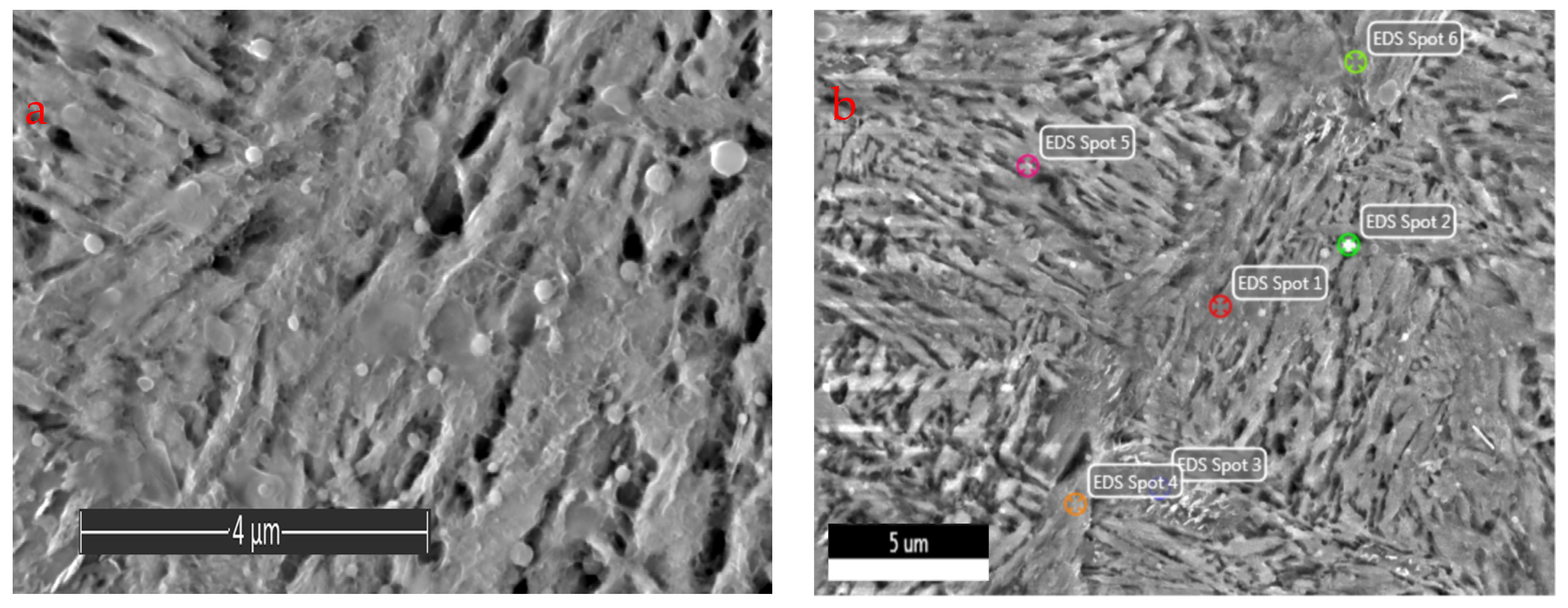
The substrate interface and microstructure were studied by scanning electron microscopy (SEM) and energy dispersive x-ray spectroscopy (EDS) using Scios, FEG and FEI. The metallographic examination was performed by optical microscope (Axio (New York, NY, USA) Observer. Z1m). Keyence (Osaka, Japan) VHX-700F optical microscope was utilized to characterize the 3D surface topography.
2.3. Mechanical Testing
The samples were cut out from the toothed segment castings. Microhardness, hardness and tensile tests were conducted to determine the mechanical properties of the obtained specimens. The static tensile tests were conducted by employing Instron (Norwood, MA, USA) 8800M hydraulic testing machines, whereas the hardness tests used Zwick/Roell typ BHO25.HZHU.3000 accordances with the PN-EN ISO 6892-1: 2016-09 and PN-EN ISO 6506-1: 2014 standards, respectively.
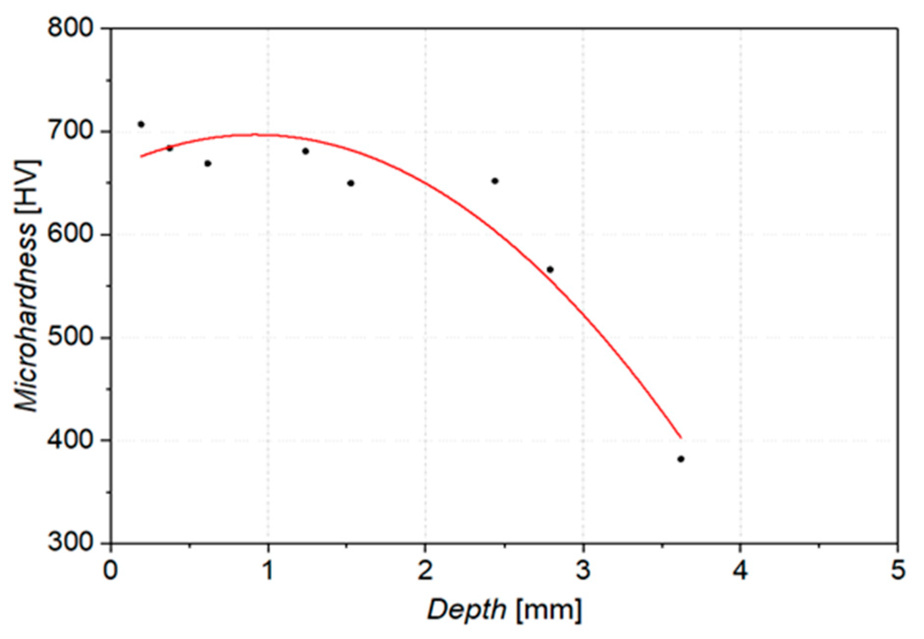
Microhardness distribution measurements were performed on an Anton Paar (Graz, Austria) microhardness device. Hardness measurements were performed using the HV hardness scale under a load of 1 N. The measurement was made on the carburized surface into the material.
2.4. Wear Testing
An abrasion test in a macro scale was carried out, which enables the measurement of wear resistance of the surface areas of the material. The Amsler and the ‘pin-on-disc’ tribological systems weres used. Initial wear tests were carried out on an Amsler-A135 (Amsler, Schaffhausen, Switzerland) machine. In a dry friction condition test, the force at the level of 577 N was applied on the sample against the counter-sample at the rotational speed of the shaft equal to 200 rpm (0.42 ms
−1), on which the counter (sample) was mounted (
Figure 2) The samples were taken from heat treated castings made from alloys selected for testing. The counter-samples were cut out from the drive wheel (20H2N4A). Measurements were made after 2, 4, 6 and 8h.
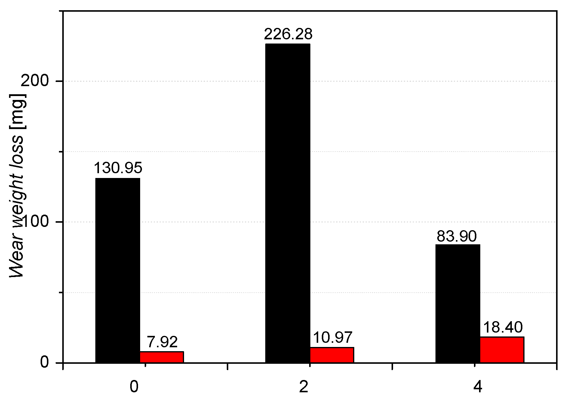
A pin-on-disc type tribometer model TR-20 was used to wear activity under dry sliding conditions. In these tests, the sample in the shape of a pin is loaded with a constant force against the rotating disk (the counter-sample), which results in the effect of friction. The measure of resistance to friction wear is the loss of sample mass as a result of the test. Before and after running the test, the weight of pins was evaluated using an electronic microbalance with high accuracy (±0.1 mg). Other indicators of the wear process are the kinetics of changes in the friction coefficient and kinetics of the total wear of the friction pair. A pin-on-disk (POD) tribo-testing machine was used to measure the wear and friction coefficient on the influence of the samples. The pins, measuring 3 mm in diameter and 25 mm in length, were made of a drive wheel. The discs measured 50 mm in diameter and 5 mm in thickness and were made of materials marked with the symbols 0, 2 and 4. Contact at the sliding interfaces was under a force of 45 N, as shown in
Figure 3. The sliding speed was 0.25 m·s
−1 for the tribological experiments, and the sliding time was 23 h. The friction distance was 22,780 m. Tests were carried out under ambient conditions. The material pairs and platform used to perform the tests are shown in
Figure 4.
2.5. Longwall Shearer Test Stand
The longwall shearers operation was carried out in the great outdoors. The haulage system and other elements necessary during the operation of the device were prepared. A stand was used to simulate the load which may occur during the longwall shearer operation in in-situ (underground) conditions. It was assumed that the largest force transmitted by a tooth would be 562 kN. The angle of rotation of the toothed bars (guide) in relation to each other is a maximum of ±0.3 degrees [
27]. During the test, the longwall shearer was driven in one direction under load and back to an idle state. The haulage system route started with a straight section, then the haulage system climbed the bend in the horizontal plane, and then the vertical bend was simulated. A total of 47 runs of the shearer were performed.
After the operation tests, the toothed segment wear measurements were carried out using the Atos III 3D optical scanner (Atos, Bezons, France). To measure the operational dimensional changes, solids of individual castings scanned before and after the tests were matched with the best-fit method. The weight loss of selected toothed segments was also determined. A Rawag WLC30/K/F (Radom, Poland) scale with a most measuring weight of 30 kg and an accuracy of 0.5 g was used to measure the weight of castings before and after the operation tests.
4. Conclusions
The paper presents the results of wear tests of driving wheel material cooperating with selected alloys as a tooth. Understanding the wear mechanisms is a crucial element of tribological study. This knowledge can help solve engineering problems. The research was carried out at a laboratory station and a test stand. In the laboratory step, Amsler-A135 and TR-20 (pin-on-disc) tribometers were used for wear tests under dry friction conditions. During the research, eight alloys were tested, which formed friction pairs with carburized alloy 20H2N4A. Depending on the material used during tests, carburized surface samples’ wear mechanism was different. Adhesive wear, micro-cutting, powling, cracks, tracks of three body wear, plastic deformation and fatigue wear was reported after experiments. After the laboratory step, alloy 0 on 350 toothed segments on the haulage system has been selected. Toothed segments were subjected to tests on the test stand. The system was tested on the ground, and the results showed an increase in the service life of the track wheel in these conditions, which can contribute to reducing operating costs in the mining process. The main conclusions of the conducted research are presented below:
The tests performed using the pin-on-disc as well as the Amsler method were consistent for sample 0, and in both cases, the pair of 0/20H2N4A alloys showed the lowest wear under dry friction.
The wear of the carburized layer of the wheel material for all the tests carried out is associated with plowing, micro-cutting, adhesive wear, oxidation wear and fatigue. However, the share of individual wear mechanisms for the tested friction pairs using the pin-on-disk method is significantly different.
A relationship was found between the temperature and the wear of the drive wheel alloy; the higher temperature recorded during the Amsler test also causes greater wear. ADI grade 1–1 cast iron is an exception here.
In the case of pin-on-disc tests, an important mechanism causing the highest wear of drive wheel material (20H2N4A) was adhesive wear.
In the case of hardness and yield strength of the tested alloys, no relationship was found between these properties and the degree of wear.
Toothed segments in places of track guide bending wear more than 2.5 times faster than in straight sections. These areas become critical places that can potentially be a source of failure of the Longwall Shearer Haulage System.
The analysis confirmed that the drive wheel was not subjected to the process of wear, which extends the service life of the entire system.
Considering the nature of the longwall shearer’s haulage system, it can be expected that during the travels, it will be necessary to adjust the drive track to the coal seams many times. The research carried out in this work confirms that it is possible to select the appropriate material for toothed critical areas (
Figure 15d). In this case, it would be necessary to divide the toothed segments into two groups. The issue that needs to be resolved is the logistical ability to separate these two groups of toothed segments in production conditions. The magnitude of the impact of these changes on the wear of the drive wheel should be checked. Further research has required the reasons for raising the friction coefficient for sample 0 during pin-on-disc tests.


 ,
, 


