
Structural Design of Nickel Hydroxide for Efficient Urea Electrooxidation

Abstract
:1. Introduction
2. Catalyst Design Engineering Principles
3. Catalyst Design Strategies
3.1. Morphology Engineering
3.2. Element Doping
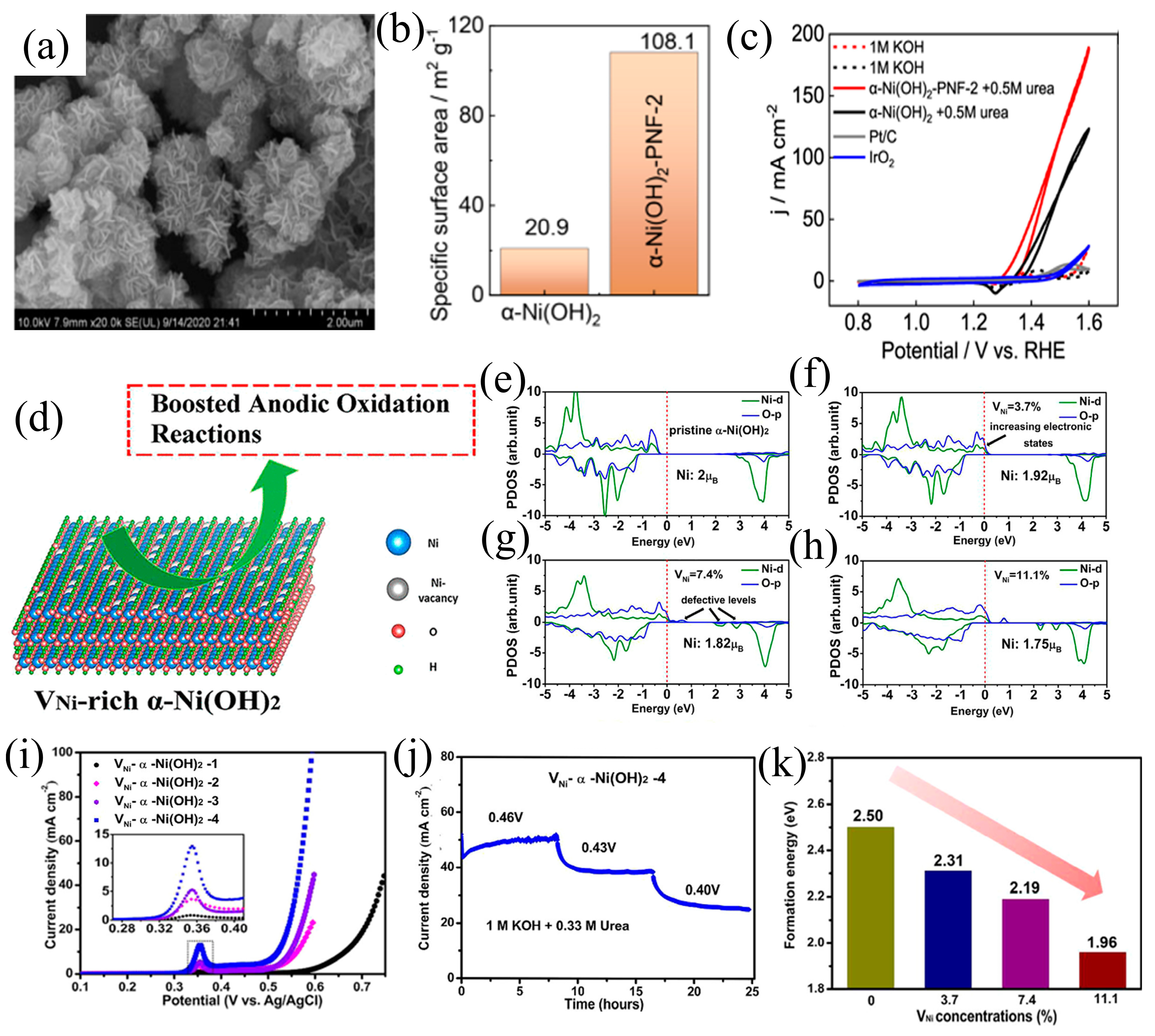
3.3. Defect Engineering
3.4. Heterostructure Construction
4. Challenges and Outlook
- (1)
- Further refinement of catalysts: enhancing the performance of Ni(OH)2 catalysts, particularly concerning long-term stability in UOR, through rational design and synthesis.
- (2)
- Mechanistic studies and surface science: undertaking more detailed characterization studies and theoretical investigations to comprehend the reaction mechanisms of nickel hydroxide catalysts in urea oxidation, thereby revealing active sites and reaction pathways for more informed design.
- (3)
- Practical applications: researchers are urged to transcend laboratory confines, engage in collaboration with industrial partners, and translate laboratory achievements into practical applications. This necessitates addressing engineering challenges and evaluating the practical effectiveness of Ni(OH)2 in various applications, including H2 production, wastewater treatment, and fuel cells.

5. Conclusions
Author Contributions
Funding
Data Availability Statement
Conflicts of Interest
References
- Wang, H.; Zheng, X.; Fang, L.; Lu, S. Urea Electrooxidation in Alkaline Environment: Fundamentals and Applications. ChemElectroChem 2023, 10, e202300138. [Google Scholar] [CrossRef]
- Hu, X.; Zhu, J.; Li, J.; Wu, Q. Urea Electrooxidation: Current Development and Understanding of Ni-Based Catalysts. ChemElectroChem 2020, 7, 3211–3228. [Google Scholar] [CrossRef]
- Rollinson, A.N.; Jones, J.; Dupont, V.; Twigg, M.V. Urea as a Hydrogen Carrier: A Perspective on Its Potential for Safe, Sustainable and Long-Term Energy Supply. Energy Environ. Sci. 2011, 4, 1216–1224. [Google Scholar] [CrossRef]
- Logan, B.E.; Rabaey, K. Conversion of Wastes into Bioelectricity and Chemicals by Using Microbial Electrochemical Technologies. Science 2012, 337, 686–690. [Google Scholar] [CrossRef] [PubMed]
- Huang, X.; He, R.; Wang, S.; Yang, Y.; Feng, L. High-Valent Ni Species Induced by Inactive MoO2 for Efficient Urea Oxidation Reaction. Inorg. Chem. 2022, 61, 18318–18324. [Google Scholar] [CrossRef] [PubMed]
- Zheng, X.; Zhang, L.; He, W.; Li, L.; Lu, S. Heteroatom-Doped Nickel Sulfide for Efficient Electrochemical Oxygen Evolution Reaction. Energies 2023, 16, 881. [Google Scholar] [CrossRef]
- Wu, C.; Fang, L.; Ding, F.; Mao, G.; Huang, X.; Lu, S. Photocatalytic Hydrogen Production from Water and Wastepaper on Pt/TiO2 Composites. Chem. Phys. Lett. 2023, 826, 140650. [Google Scholar] [CrossRef]
- Diao, Y.; Liu, Y.; Hu, G.; Zhao, Y.; Qian, Y.; Wang, H.; Shi, Y.; Li, Z. NiFe Nanosheets as Urea Oxidation Reaction Electrocatalysts for Urea Removal and Energy-Saving Hydrogen Production. Biosens. Bioelectron. 2022, 211, 114380. [Google Scholar] [CrossRef] [PubMed]
- Kim, K.; Tiwari, A.P.; Hyun, G.; Yoon, Y.; Kim, H.; Park, J.Y.; An, K.-S.; Jeon, S. Continuous 3D-Nanopatterned Ni–Mo Solid Solution as a Free-Standing Electrocatalyst for the Hydrogen Evolution Reaction in Alkaline Medium. J. Mater. Chem. A 2021, 9, 7767–7773. [Google Scholar] [CrossRef]
- Tiwari, A.P.; Yoon, Y.; Novak, T.G.; An, K.-S.; Jeon, S. Continuous Network of Phase-Tuned Nickel Sulfide Nanostructures for Electrocatalytic Water Splitting. ACS Appl. Nano Mater. 2019, 2, 5061–5070. [Google Scholar] [CrossRef]
- Lu, S.; Zheng, X.; Fang, L.; Yin, F.; Liu, H. Rational Engineering Design of Nickel Hydroxides for Urea Oxidation Reaction: A Mini-Review. Electrochem. Commun. 2023, 157, 107599. [Google Scholar] [CrossRef]
- Lv, L.; Yang, Z.; Chen, K.; Wang, C.; Xiong, Y. 2D Layered Double Hydroxides for Oxygen Evolution Reaction: From Fundamental Design to Application. Adv. Energy Mater. 2019, 9, 1803358. [Google Scholar] [CrossRef]
- Durst, J.; Siebel, A.; Simon, C.; Hasché, F.; Herranz, J.; Gasteiger, H.A. New Insights into the Electrochemical Hydrogen Oxidation and Evolution Reaction Mechanism. Energy Environ. Sci. 2014, 7, 2255–2260. [Google Scholar] [CrossRef]
- Liao, W.; Zhao, Q.; Wang, S.; Ran, Y.; Su, H.; Gan, R.; Lu, S.; Zhang, Y. Insights into Mechanisms on Electrochemical Oxygen Evolution Substitution Reactions. J. Catal. 2023, 428, 115161. [Google Scholar] [CrossRef]
- Ma, M.; Yu, H.; Deng, L.; Wang, L.; Liu, S.; Pan, H.; Ren, J.; Yu, M.; Hu, F.; Peng, S. Interfacial engineering of heterostructured carbon-supported molybdenum cobalt sulfides for efficient overall water splitting. Tungsten 2023, 5, 589–597. [Google Scholar] [CrossRef]
- Lu, S.; Hummel, M.; Gu, Z.; Gu, Y.; Cen, Z.; Wei, L.; Zhou, Y.; Zhang, C.; Yang, C. Trash to Treasure: A Novel Chemical Route to Synthesis of NiO/C for Hydrogen Production. Int. J. Hydrogen Energy 2019, 44, 16144–16153. [Google Scholar] [CrossRef]
- Tang, C.; Zhang, R.; Lu, W.; Wang, Z.; Liu, D.; Hao, S.; Du, G.; Asiri, A.M.; Sun, X. Energy-saving Electrolytic Hydrogen Generation: Ni2P Nanoarray as a High-performance Non-noble-metal Electrocatalyst. Angew. Chem. Int. Ed. 2017, 56, 842–846. [Google Scholar] [CrossRef] [PubMed]
- Zhang, H.; Zeng, X.; Zhang, Q.; Zhang, Z.; Jin, C.; Yu, R. Dual template-induced construction of three-dimensional porous SiO2/NC/Co-CNTs heterostructure with highly dispersed active sites for efficient oxygen evolution reaction. Tungsten 2023. [Google Scholar] [CrossRef]
- Chen, S.; Duan, J.; Vasileff, A.; Qiao, S.Z. Size Fractionation of Two-dimensional Sub-nanometer Thin Manganese Dioxide Crystals towards Superior Urea Electrocatalytic Conversion. Angew. Chem. Int. Ed. 2016, 55, 3804–3808. [Google Scholar] [CrossRef]
- King, R.L.; Botte, G.G. Investigation of Multi-Metal Catalysts for Stable Hydrogen Production via Urea Electrolysis. J. Power Sources 2011, 196, 9579–9584. [Google Scholar] [CrossRef]
- Xie, X.; Du, L.; Yan, L.; Park, S.; Qiu, Y.; Sokolowski, J.; Wang, W.; Shao, Y. Oxygen Evolution Reaction in Alkaline Environment: Material Challenges and Solutions. Adv. Funct. Mater. 2022, 32, 2110036. [Google Scholar] [CrossRef]
- Tahir, M.; Pan, L.; Idrees, F.; Zhang, X.; Wang, L.; Zou, J.-J.; Wang, Z.L. Electrocatalytic Oxygen Evolution Reaction for Energy Conversion and Storage: A Comprehensive Review. Nano Energy 2017, 37, 136–157. [Google Scholar] [CrossRef]
- Li, J.; Wang, S.; Chang, J.; Feng, L. A Review of Ni Based Powder Catalyst for Urea Oxidation in Assisting Water Splitting Reaction. Adv. Powder Mater. 2022, 1, 100030. [Google Scholar] [CrossRef]
- Wang, S.; Zhao, L.; Li, J.; Tian, X.; Wu, X.; Feng, L. High Valence State of Ni and Mo Synergism in NiS2-MoS2 Hetero-Nanorods Catalyst with Layered Surface Structure for Urea Electrocatalysis. J. Energy Chem. 2022, 66, 483–492. [Google Scholar] [CrossRef]
- Lan, R.; Tao, S. Preparation of Nano-Sized Nickel as Anode Catalyst for Direct Urea and Urine Fuel Cells. J. Power Sources 2011, 196, 5021–5026. [Google Scholar] [CrossRef]
- Ding, R.; Qi, L.; Jia, M.; Wang, H. Facile Synthesis of Mesoporous Spinel NiCo2O4 Nanostructures as Highly Efficient Electrocatalysts for Urea Electro-Oxidation. Nanoscale 2014, 6, 1369–1376. [Google Scholar] [CrossRef] [PubMed]
- Liang, Y.; Liu, Q.; Asiri, A.M.; Sun, X. Enhanced Electrooxidation of Urea Using NiMoO4· xH2O Nanosheet Arrays on Ni Foam as Anode. Electrochim. Acta 2015, 153, 456–460. [Google Scholar] [CrossRef]
- Daramola, D.A.; Singh, D.; Botte, G.G. Dissociation Rates of Urea in the Presence of NiOOH Catalyst: A DFT Analysis. J. Phys. Chem. A 2010, 114, 11513–11521. [Google Scholar] [CrossRef] [PubMed]
- Vedharathinam, V.; Botte, G.G. Experimental Investigation of Potential Oscillations during the Electrocatalytic Oxidation of Urea on Ni Catalyst in Alkaline Medium. J. Phys. Chem. C 2014, 118, 21806–21812. [Google Scholar] [CrossRef]
- Xu, W.; Zhang, H.; Li, G.; Wu, Z. Nickel-Cobalt Bimetallic Anode Catalysts for Direct Urea Fuel Cell. Sci. Rep. 2014, 4, 5863. [Google Scholar] [CrossRef]
- Guo, F.; Cheng, K.; Ye, K.; Wang, G.; Cao, D. Preparation of Nickel-Cobalt Nanowire Arrays Anode Electro-Catalyst and Its Application in Direct Urea/Hydrogen Peroxide Fuel Cell. Electrochim. Acta 2016, 199, 290–296. [Google Scholar] [CrossRef]
- He, Q.; Wan, Y.; Jiang, H.; Pan, Z.; Wu, C.; Wang, M.; Wu, X.; Ye, B.; Ajayan, P.M.; Song, L. Nickel Vacancies Boost Reconstruction in Nickel Hydroxide Electrocatalyst. ACS Energy Lett. 2018, 3, 1373–1380. [Google Scholar] [CrossRef]
- Xu, B.; Yang, X.; Liu, X.; Song, W.; Sun, Y.; Liu, Q.; Yang, H.; Li, C. Lattice Distortion in Hybrid NiTe2/Ni (OH)2 Nanosheets as Efficient Synergistic Electrocatalyst for Water and Urea Oxidation. J. Power Sources 2020, 449, 227585. [Google Scholar] [CrossRef]
- Yang, W.; Yang, X.; Li, B.; Lin, J.; Gao, H.; Hou, C.; Luo, X. Ultrathin Nickel Hydroxide Nanosheets with a Porous Structure for Efficient Electrocatalytic Urea Oxidation. J. Mater. Chem. A 2019, 7, 26364–26370. [Google Scholar] [CrossRef]
- Gan, Q.; Cheng, X.; Chen, J.; Wang, D.; Wang, B.; Tian, J.; Isimjan, T.T.; Yang, X. Temperature Effect on Crystallinity and Chemical States of Nickel Hydroxide as Alternative Superior Catalyst for Urea Electrooxidation. Electrochim. Acta 2019, 301, 47–54. [Google Scholar] [CrossRef]
- Wang, D.; Yan, W.; Botte, G.G. Exfoliated Nickel Hydroxide Nanosheets for Urea Electrolysis. Electrochem. Commun. 2011, 13, 1135–1138. [Google Scholar] [CrossRef]
- Wang, D.; Yan, W.; Vijapur, S.H.; Botte, G.G. Enhanced Electrocatalytic Oxidation of Urea Based on Nickel Hydroxide Nanoribbons. J. Power Sources 2012, 217, 498–502. [Google Scholar] [CrossRef]
- Boggs, B.K.; King, R.L.; Botte, G.G. Urea Electrolysis: Direct Hydrogen Production from Urine. Chem. Commun. 2009, 32, 4859–4861. [Google Scholar] [CrossRef]
- King, R.L.; Botte, G.G. Hydrogen Production via Urea Electrolysis Using a Gel Electrolyte. J. Power Sources 2011, 196, 2773–2778. [Google Scholar] [CrossRef]
- Vedharathinam, V.; Botte, G.G. Understanding the Electro-Catalytic Oxidation Mechanism of Urea on Nickel Electrodes in Alkaline Medium. Electrochim. Acta 2012, 81, 292–300. [Google Scholar] [CrossRef]
- Zhang, H.; Bruns, M.A.; Logan, B.E. Biological Hydrogen Production by Clostridium Acetobutylicum in an Unsaturated Flow Reactor. Water Res. 2006, 40, 728–734. [Google Scholar] [CrossRef]
- Zhou, L.; Cheng, Y.F. Catalytic Electrolysis of Ammonia on Platinum in Alkaline Solution for Hydrogen Generation. Int. J. Hydrogen Energy 2008, 33, 5897–5904. [Google Scholar] [CrossRef]
- Vedharathinam, V.; Botte, G.G. Direct Evidence of the Mechanism for the Electro-Oxidation of Urea on Ni(OH)2 Catalyst in Alkaline Medium. Electrochim. Acta 2013, 108, 660–665. [Google Scholar] [CrossRef]
- Vidotti, M.; Silva, M.R.d.; Salvador, R.P.; De Torresi, S.C.; Dall’Antonia, L.H. Electrocatalytic Oxidation of Urea by Nanostructured Nickel/Cobalt Hydroxide Electrodes. Electrochim. Acta 2008, 53, 4030–4034. [Google Scholar] [CrossRef]
- Li, X.; Liu, X.; Liu, C.; Zeng, J.; Qi, X. Co3O4/stainless steel catalyst with synergistic effect of oxygen vacancies and phosphorus doping for overall water splitting. Tungsten 2023, 5, 100–108. [Google Scholar] [CrossRef]
- Xiao, W.; Liu, P.; Zhang, J.; Song, W.; Feng, Y.P.; Gao, D.; Ding, J. Dual-functional N Dopants in Edges and Basal Plane of MoS2 Nanosheets toward Efficient and Durable Hydrogen Evolution. Adv. Energy Mater. 2017, 7, 1602086. [Google Scholar] [CrossRef]
- Xie, J.; Zhang, H.; Li, S.; Wang, R.; Sun, X.; Zhou, M.; Zhou, J.; Lou, X.W.; Xie, Y. Defect-rich MoS2 Ultrathin Nanosheets with Additional Active Edge Sites for Enhanced Electrocatalytic Hydrogen Evolution. Adv. Mater. 2013, 25, 5807–5813. [Google Scholar] [CrossRef]
- Barakat, N.A.; Alajami, M.; Al Haj, Y.; Obaid, M.; Al-Meer, S. Enhanced Onset Potential NiMn-Decorated Activated Carbon as Effective and Applicable Anode in Urea Fuel Cells. Catal. Commun. 2017, 97, 32–36. [Google Scholar] [CrossRef]
- Chen, X.; Yu, M.; Yan, Z.; Guo, W.; Fan, G.; Ni, Y.; Liu, J.; Zhang, W.; Xie, W.; Cheng, F. Boosting Electrocatalytic Oxygen Evolution by Cation Defect Modulation via Electrochemical Etching. CCS Chem. 2021, 3, 675–685. [Google Scholar] [CrossRef]
- Ren, Y.; Wang, C.; Duan, W.; Zhou, L.; Pang, X.; Wang, D.; Zhen, Y.; Yang, C.; Gao, Z. MoS2/Ni3S2 Schottky Heterojunction Regulating Local Charge Distribution for Efficient Urea Oxidation and Hydrogen Evolution. J. Colloid Interface Sci. 2022, 628, 446–455. [Google Scholar] [CrossRef]
- Ding, Y.; Li, Y.; Xue, Y.; Miao, B.; Li, S.; Jiang, Y.; Liu, X.; Chen, Y. Atomically Thick Ni(OH)2 Nanomeshes for Urea Electrooxidation. Nanoscale 2019, 11, 1058–1064. [Google Scholar] [CrossRef] [PubMed]
- Lin, C.; Gao, Z.; Zhang, F.; Yang, J.; Liu, B.; Jin, J. In Situ Growth of Single-Layered α-Ni (OH)2 Nanosheets on a Carbon Cloth for Highly Efficient Electrocatalytic Oxidation of Urea. J. Mater. Chem. A 2018, 6, 13867–13873. [Google Scholar] [CrossRef]
- Sha, L.; Ye, K.; Yin, J.; Zhu, K.; Cheng, K.; Yan, J.; Wang, G.; Cao, D. In Situ Grown 3D Hierarchical MnCo2O4.5@Ni(OH)2 Nanosheet Arrays on Ni Foam for Efficient Electrocatalytic Urea Oxidation. Chem. Eng. J. 2020, 381, 122603. [Google Scholar] [CrossRef]
- Cheng, Y.; Zhu, L.; Gong, Y. Ce Doped Ni (OH)2/Ni-MOF Nanosheets as an Efficient Oxygen Evolution and Urea Oxidation Reactions Electrocatalyst. Int. J. Hydrogen Energy 2024, 58, 416–425. [Google Scholar] [CrossRef]
- Xiang, L.; Zhang, W.; Xu, H.; Hu, M.; Yang, J.; Liu, J.; Gu, Z.; Yan, X. Hierarchical Microspheres Constructed by Hexagonal NiCo(OH)2 Nanosheets with Rich Ni3+ Species and Carboxylic Groups for Efficient Urea Oxidation Reaction. J. Alloys Compd. 2023, 930, 167453. [Google Scholar] [CrossRef]
- Yue, Z.; Yao, S.; Li, Y.; Zhu, W.; Zhang, W.; Wang, R.; Wang, J.; Huang, L.; Zhao, D.; Wang, J. Surface Engineering of Hierarchical Ni(OH)2 Nanosheet@ Nanowire Configuration toward Superior Urea Electrolysis. Electrochim. Acta 2018, 268, 211–217. [Google Scholar] [CrossRef]
- Jiang, P.; Liu, Q.; Liang, Y.; Tian, J.; Asiri, A.M.; Sun, X. A Cost-effective 3D Hydrogen Evolution Cathode with High Catalytic Activity: FeP Nanowire Array as the Active Phase. Angew. Chem. 2014, 126, 13069–13073. [Google Scholar] [CrossRef]
- Tian, J.; Liu, Q.; Asiri, A.M.; Sun, X. Self-Supported Nanoporous Cobalt Phosphide Nanowire Arrays: An Efficient 3D Hydrogen-Evolving Cathode over the Wide Range of pH 0–14. J. Am. Chem. Soc. 2014, 136, 7587–7590. [Google Scholar] [CrossRef] [PubMed]
- Luo, Q.; Peng, M.; Sun, X.; Asiri, A.M. Hierarchical Nickel Oxide Nanosheet@ Nanowire Arrays on Nickel Foam: An Efficient 3D Electrode for Methanol Electro-Oxidation. Catal. Sci. Technol. 2016, 6, 1157–1161. [Google Scholar] [CrossRef]
- Zhu, W.; Zhang, R.; Qu, F.; Asiri, A.M.; Sun, X. Design and Application of Foams for Electrocatalysis. ChemCatChem 2017, 9, 1721–1743. [Google Scholar] [CrossRef]
- Tang, C.; Zhao, Z.L.; Chen, J.; Li, B.; Chen, L.; Li, C.M. Se-Ni(OH)2-Shelled Vertically Oriented NiSe Nanowires as a Superior Electrocatalyst toward Urea Oxidation Reaction of Fuel Cells. Electrochim. Acta 2017, 248, 243–249. [Google Scholar] [CrossRef]
- Wang, H.; Zhang, L.; Jiang, H.; Kannan, P.; Wang, R.; Subramanian, P.; Ji, S. Rational Construction of Hierarchical Ni(OH)2–NiS in-Plane Edge Hybrid Nanosheet Structures on the Carbon Cloth as a Robust Catalyst for Electro-Oxidation of Urea. J. Alloys Compd. 2021, 870, 159486. [Google Scholar] [CrossRef]
- Xie, J.; Liu, W.; Lei, F.; Zhang, X.; Qu, H.; Gao, L.; Hao, P.; Tang, B.; Xie, Y. Iron-Incorporated α-Ni(OH)2 Hierarchical Nanosheet Arrays for Electrocatalytic Urea Oxidation. Chem.-A Eur. J. 2018, 24, 18408–18412. [Google Scholar] [CrossRef] [PubMed]
- Li, Q.; Li, N.; An, J.; Pang, H. Controllable Synthesis of a Mesoporous NiO/Ni Nanorod as an Excellent Catalyst for Urea Electro-Oxidation. Inorg. Chem. Front. 2020, 7, 2089–2096. [Google Scholar] [CrossRef]
- Zhang, Z.; Lu, S.; Li, Y.; Song, J.; Han, E.; Wang, H.; He, Y. Promoting Hierarchical Porous Carbon Derived from Bamboo via Copper Doping for High-Performance Supercapacitors. Ind. Crops Prod. 2023, 203, 117155. [Google Scholar] [CrossRef]
- Ede, S.R.; Luo, Z. Tuning the Intrinsic Catalytic Activities of Oxygen-Evolution Catalysts by Doping: A Comprehensive Review. J. Mater. Chem. A 2021, 9, 20131–20163. [Google Scholar] [CrossRef]
- Zhang, Y.; Cheng, C.-Q.; Kuai, C.-G.; Sokaras, D.; Zheng, X.-L.; Sainio, S.; Lin, F.; Dong, C.-K.; Nordlund, D.; Du, X.-W. Unveiling the Critical Role of the Mn Dopant in a NiFe(OH)2 Catalyst for Water Oxidation. J. Mater. Chem. A 2020, 8, 17471–17476. [Google Scholar] [CrossRef]
- Yang, X.; Zhang, H.; Xu, W.; Yu, B.; Liu, Y.; Wu, Z. A Doping Element Improving the Properties of Catalysis: In Situ Raman Spectroscopy Insights into Mn-Doped NiMn Layered Double Hydroxide for the Urea Oxidation Reaction. Catal. Sci. Technol. 2022, 12, 4471–4485. [Google Scholar] [CrossRef]
- Xie, J.; Qu, H.; Lei, F.; Peng, X.; Liu, W.; Gao, L.; Hao, P.; Cui, G.; Tang, B. Partially Amorphous Nickel–Iron Layered Double Hydroxide Nanosheet Arrays for Robust Bifunctional Electrocatalysis. J. Mater. Chem. A 2018, 6, 16121–16129. [Google Scholar] [CrossRef]
- Trotochaud, L.; Young, S.L.; Ranney, J.K.; Boettcher, S.W. Nickel–Iron Oxyhydroxide Oxygen-Evolution Electrocatalysts: The Role of Intentional and Incidental Iron Incorporation. J. Am. Chem. Soc. 2014, 136, 6744–6753. [Google Scholar] [CrossRef]
- Xie, J.; Gao, L.; Cao, S.; Liu, W.; Lei, F.; Hao, P.; Xia, X.; Tang, B. Copper-Incorporated Hierarchical Wire-on-Sheet α-Ni(OH)2 Nanoarrays as Robust Trifunctional Catalysts for Synergistic Hydrogen Generation and Urea Oxidation. J. Mater. Chem. A 2019, 7, 13577–13584. [Google Scholar] [CrossRef]
- Cao, Q.; Yuan, Y.; Wang, K.; Huang, W.; Zhao, Y.; Sun, X.; Ding, R.; Lin, W.; Liu, E.; Gao, P. Phase and Crystallinity Regulations of Ni(OH)2 by Vanadium Doping Boost Electrocatalytic Urea Oxidation Reaction. J. Colloid Interface Sci. 2022, 618, 411–418. [Google Scholar] [CrossRef] [PubMed]
- Xie, J.; Liu, W.; Zhang, X.; Guo, Y.; Gao, L.; Lei, F.; Tang, B.; Xie, Y. Constructing Hierarchical Wire-on-Sheet Nanoarrays in Phase-Regulated Cerium-Doped Nickel Hydroxide for Promoted Urea Electro-Oxidation. ACS Mater. Lett. 2019, 1, 103–110. [Google Scholar] [CrossRef]
- Miao, F.; Cui, P.; Gu, T.; Yu, S.; Yan, Z.; Hai, G. Dual Cation-Modified Hierarchical Nickel Hydroxide Nanosheet Arrays as Efficient and Robust Electrocatalysts for the Urea Oxidation Reaction. Dalton Trans. 2024, 53, 1599–1606. [Google Scholar] [CrossRef] [PubMed]
- Yang, M.; Liu, Y.; Ge, W.; Liu, Z. Enhanced Electrocatalytic Activity of Sulfur and Tungsten Co-Doped Nickel Hydroxide Nanosheets for Urea Oxidation. Colloids Surf. A Physicochem. Eng. Asp. 2023, 665, 131226. [Google Scholar] [CrossRef]
- Patil, S.J.; Chodankar, N.R.; Hwang, S.-K.; Rama Raju, G.S.; Huh, Y.-S.; Han, Y.-K. Fluorine Engineered Self-Supported Ultrathin 2D Nickel Hydroxide Nanosheets as Highly Robust and Stable Bifunctional Electrocatalysts for Oxygen Evolution and Urea Oxidation Reactions. Small 2022, 18, 2103326. [Google Scholar] [CrossRef]
- Yan, D.; Li, Y.; Huo, J.; Chen, R.; Dai, L.; Wang, S. Defect Chemistry of Nonprecious-Metal Electrocatalysts for Oxygen Reactions. Adv. Mater. 2017, 29, 1606459. [Google Scholar] [CrossRef]
- Fang, L.; Wang, S.; Song, C.; Lu, S.; Yang, X.; Qi, X.; Liu, H. Boosting Nitrate Electroreduction to Ammonia via in Situ Generated Stacking Faults in Oxide-Derived Copper. Chem. Eng. J. 2022, 446, 137341. [Google Scholar] [CrossRef]
- Liu, C.; Wang, B.; Xu, L.; Zou, K.; Deng, W.; Hou, H.; Zou, G.; Ji, X. Novel Nonstoichiometric Niobium Oxide Anode Material with Rich Oxygen Vacancies for Advanced Lithium-Ion Capacitors. ACS Appl. Mater. Interfaces 2023, 15, 5387–5398. [Google Scholar] [CrossRef]
- Wu, Z.; Zhao, Y.; Jin, W.; Jia, B.; Wang, J.; Ma, T. Recent Progress of Vacancy Engineering for Electrochemical Energy Conversion Related Applications. Adv. Funct. Mater. 2021, 31, 2009070. [Google Scholar] [CrossRef]
- Li, Y.; Luo, F.; Xie, Y.; Chang, C.; Xie, M.; Yang, Z. Oxygen Vacancies in α-Ni(OH)2 Porous Nanoflowers Promote Urea Oxidation. Int. J. Hydrogen Energy 2023, 48, 9155–9162. [Google Scholar] [CrossRef]
- Qin, H.; Ye, Y.; Li, J.; Jia, W.; Zheng, S.; Cao, X.; Lin, G.; Jiao, L. Synergistic Engineering of Doping and Vacancy in Ni(OH)2 to Boost Urea Electrooxidation. Adv Funct Mater. 2023, 33, 2209698. [Google Scholar] [CrossRef]
- Liu, Y.; Yang, Z.; Zou, Y.; Wang, S.; He, J. Trace Cobalt Doping and Defect Engineering of High Surface Area α-Ni(OH)2 for Electrocatalytic Urea Oxidation. Energy Environ. Mater. 2023, 7, e12576. [Google Scholar] [CrossRef]
- Wang, Z.; Hu, Y.; Liu, W.; Xu, L.; Guan, M.; Zhao, Y.; Bao, J.; Li, H. Manganese-Modulated Cobalt-Based Layered Double Hydroxide Grown on Nickel Foam with 1D–2D–3D Heterostructure for Highly Efficient Oxygen Evolution Reaction and Urea Oxidation Reaction. Chem.-A Eur. J. 2020, 26, 9382–9388. [Google Scholar] [CrossRef]
- Babar, P.; Lokhande, A.; Karade, V.; Lee, I.J.; Lee, D.; Pawar, S.; Kim, J.H. Trifunctional Layered Electrodeposited Nickel Iron Hydroxide Electrocatalyst with Enhanced Performance towards the Oxidation of Water, Urea and Hydrazine. J. Colloid Interface Sci. 2019, 557, 10–17. [Google Scholar] [CrossRef]
- Zhu, Y.; Wu, X. Heterostructured Materials. Prog. Mater. Sci. 2023, 131, 101019. [Google Scholar] [CrossRef]
- Ye, Y.; Gan, Y.; Cai, R.; Dai, X.; Yin, X.; Nie, F.; Ren, Z.; Wu, B.; Cao, Y.; Zhang, X. Oxygen Vacancies and Surface Reconstruction on NiFe LDH@Ni(OH)2 Heterojunction Synergistically Triggering Oxygen Evolution and Urea Oxidation Reaction. J. Alloys Compd. 2022, 921, 166145. [Google Scholar] [CrossRef]
- Liu, L.; Ge, L.; Sun, Y.; Jiang, B.; Cheng, Y.; Xu, L.; Liao, F.; Kang, Z.; Shao, M. Quasi-Layer Co 2 P-Polarized Cu 3 P Nanocomposites with Enhanced Intrinsic Interfacial Charge Transfer for Efficient Overall Water Splitting. Nanoscale 2019, 11, 6394–6400. [Google Scholar] [CrossRef] [PubMed]
- Cheng, Y.; Liao, F.; Dong, H.; Wei, H.; Geng, H.; Shao, M. Engineering CoN/Ni(OH)2 Heterostructures with Improved Intrinsic Interfacial Charge Transfer toward Simultaneous Hydrogen Generation and Urea-Rich Wastewater Purification. J. Power Sources 2020, 480, 229151. [Google Scholar] [CrossRef]
- Zhao, T.; Wang, S.; Li, Y.; Jia, C.; Su, Z.; Hao, D.; Ni, B.; Zhang, Q.; Zhao, C. Heterostructured V-Doped Ni2P/Ni12P5 Electrocatalysts for Hydrogen Evolution in Anion Exchange Membrane Water Electrolyzers. Small 2022, 18, 2204758. [Google Scholar] [CrossRef]
- Yang, H.; Ge, L.; Guan, J.; Ouyang, B.; Li, H.; Deng, Y. Synergistic Engineering of Heteroatom Doping and Heterointerface Construction in V-Doped Ni(OH)2/FeOOH to Boost Both Oxygen Evolution and Urea Oxidation Reactions. J. Colloid Interface Sci. 2024, 653, 721–729. [Google Scholar] [CrossRef] [PubMed]
- Gao, C.; Wei, G.; Wang, C.; Zhou, X.; Zhao, X.; Zhao, Q.; Wang, S.; Kong, F. In Situ Topologically Induced Metastable Phase Ni/r-Ni(OH)2@C Heterostructures with Abundant Oxygen Vacancies as Efficient Bifunctional Electrocatalysts for Energy-Saving Hydrogen Production. J. Alloys Compd. 2023, 959, 170545. [Google Scholar] [CrossRef]


| Catalyst | KOH and Urea | Potential/V | Current Density/mA cm−2 | ECSA or Tafel Slope | Ref. |
|---|---|---|---|---|---|
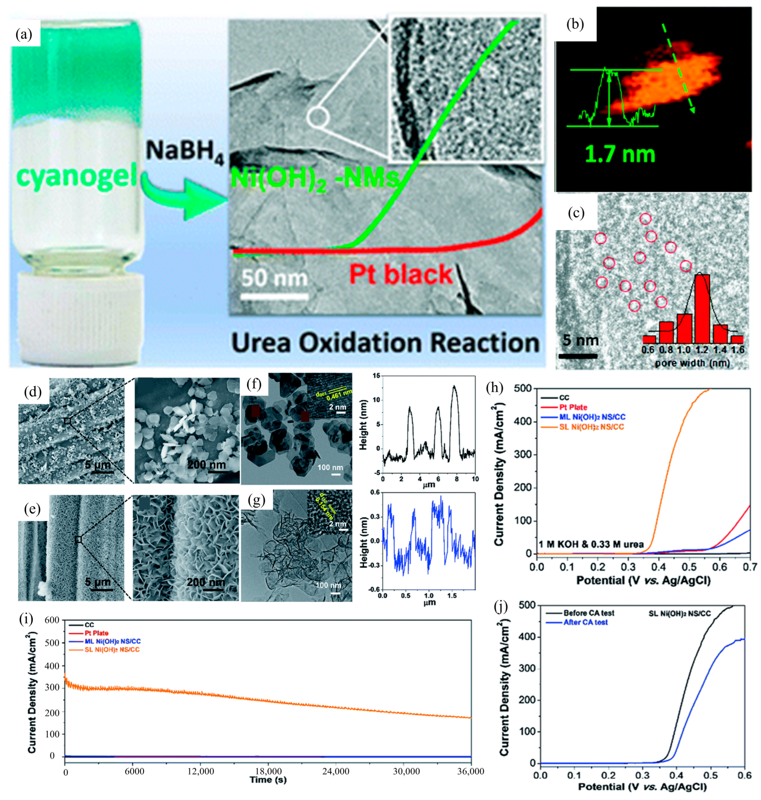
| Ni(OH)2-NMs | 1 M and 0.33 M | 1.35 (vs. RHE) | 10 | 231 mV dec−1 | [51] |
| SL α-Ni(OH)2 NS/CC | 1 M and 0.33 M | 0.4 (Ag/AgCl) | 100 | 130.2 mF cm−2 | [52] |
| MnCo2O4.5@Ni(OH)2/NF | 5 M and 0.33 M | 0.6 (Ag/AgCl) | 650 | 29.0 mF cm−2 | [53] |
| Ce-Ni(OH)2@Ni-MOF/NF | 1 M and 0.5 M | 1.28 (vs. RHE) | 10 | 24.65 mV dec−1 | [54] |
| NiCo(OH)2 | 1 M and 0.33 M | 1.368 (vs. RHE) | 100 | 231 mV dec−1 | [55] |
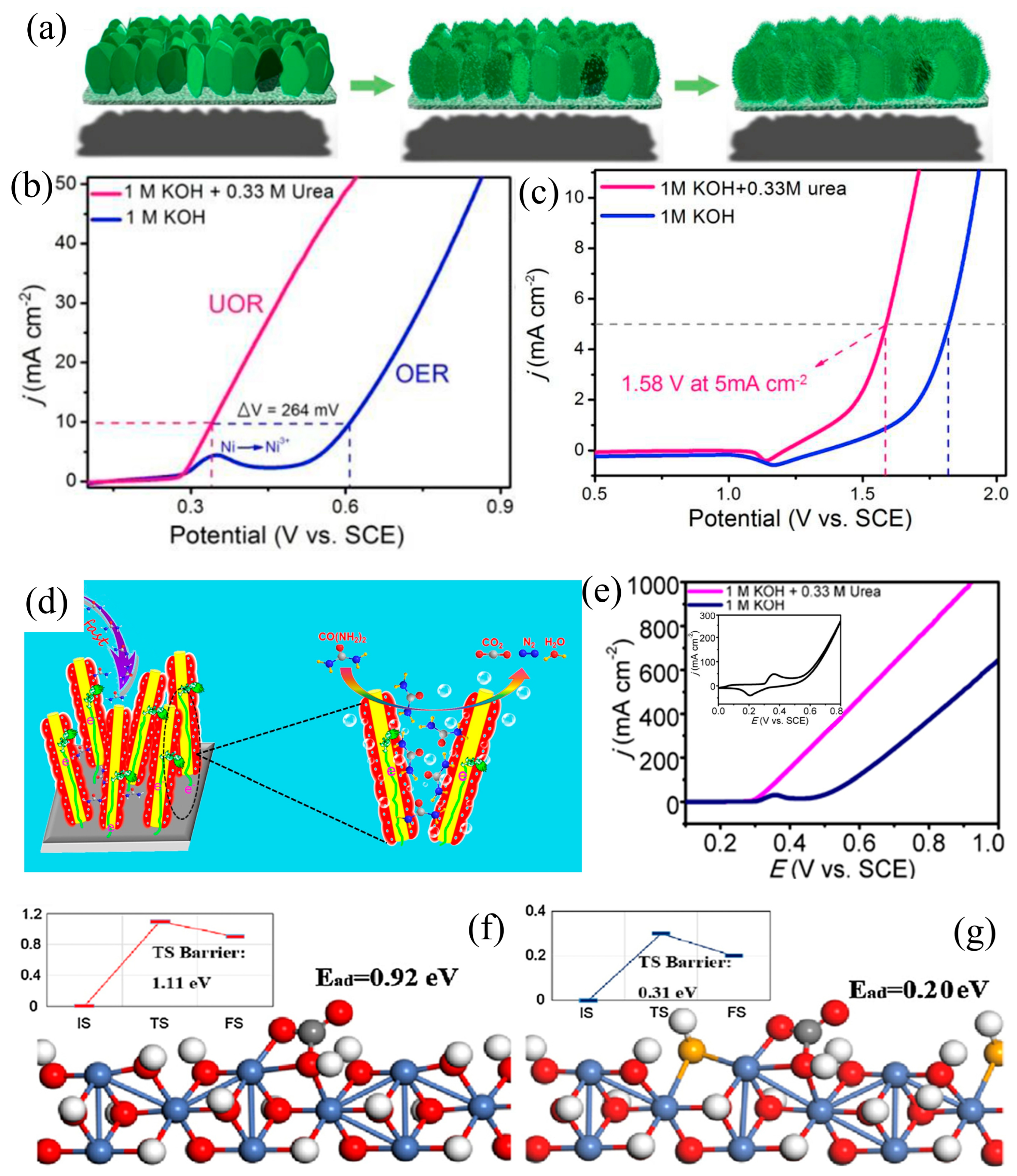
| Ni(OH)2 NS@NW/NF | 1 M and 0.33 M | 1.58 (vs. SCE) | 5 | 47 mV dec−1 | [56] |
| Se-Ni(OH)2@NiSe/NF | 1 M and 0.33 M | 0.366 (vs. SCE) | 100 | 31.2 mF cm−2 | [61] |
| Catalysts | KOH and Urea | Potential/V | Current Density | ECSA or Tafel Slope | Ref. |
|---|---|---|---|---|---|
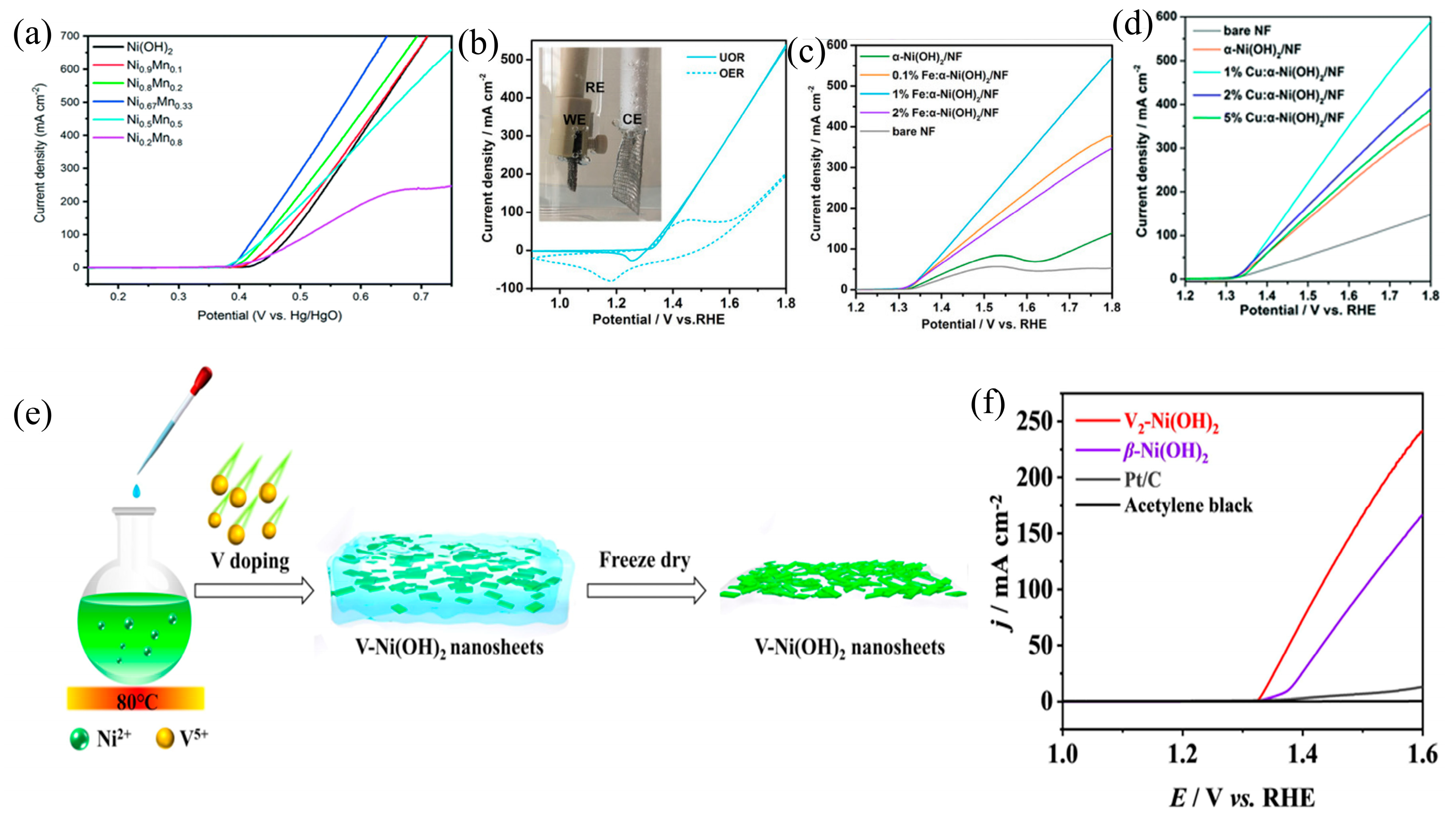
| Ni0.2Mn0.8 LDHs | 1 M and 0.33 M | 0.44 (vs. Hg/HgO) | 100 mA cm−2 | 23.8 mV dec−1 | [68] |
| Fe-α(OH)2/NF | 1 M and 0.33 M | 1.408 (vs. RHE) | 100 mA cm−2 | 35 mV dec−1 | [63] |
| Cu-α-Ni(OH)2/NF | 1 M and 0.33 M | 1.45 (vs. RHE) | 100 mA cm−2 | 1.32 mF cm−2 | [71] |
| V-Ni(OH)2 | 1 M and 0.33 M | 1.6 (vs. RHE) | 241 mA cm−2 | 32.15 mV dec−1 | [72] |
| S,W-Ni(OH)2 | 1 M and 0.33 M | 0.6 (Ag/AgCl) | 100 mA cm−2 | 106.1 mF cm−2 | [75] |
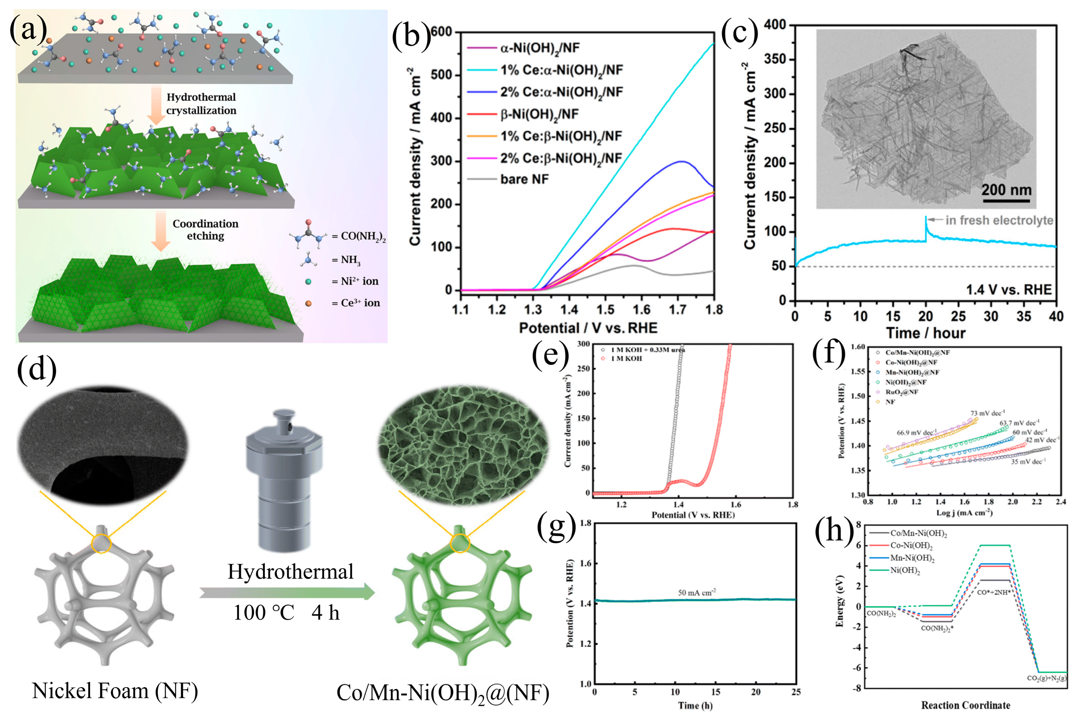
| 1% Ce:α-Ni(OH)2/NF | 1 M and 0.33 M | 1.8 (vs. RHE) | 579.5 mA cm−2 | 25 mV dec−1 | [73] |
| Co/Mn-Ni (OH)2 | 1 M and 0.33 M | 1.38 (vs. RHE) | 100 mA cm−2 | 35 mV dec−1 | [74] |
| F-Ni(OH)2 | 1 M and 0.33 M | 1.16 (vs. RHE) | 10 mA cm−2 | 29.36 mV dec−1 | [76] |
| Catalysts | KOH and Urea | Potential/V | Current Density | ECSA or Tafel Slope | Ref. |
|---|---|---|---|---|---|
| α-Ni(OH)2-PNF | 1 M and 0.5 M | 1.477 (vs. RHE) | 100 mA cm−2 | 7.0 mF cm−2 | [81] |
| VNi-α-Ni(OH)2 | 1 M and 0.33 M | 0.36 (vs. Ag/AgCl) | 10 mA cm−2 | 29.7 mV dec−1 | [32] |
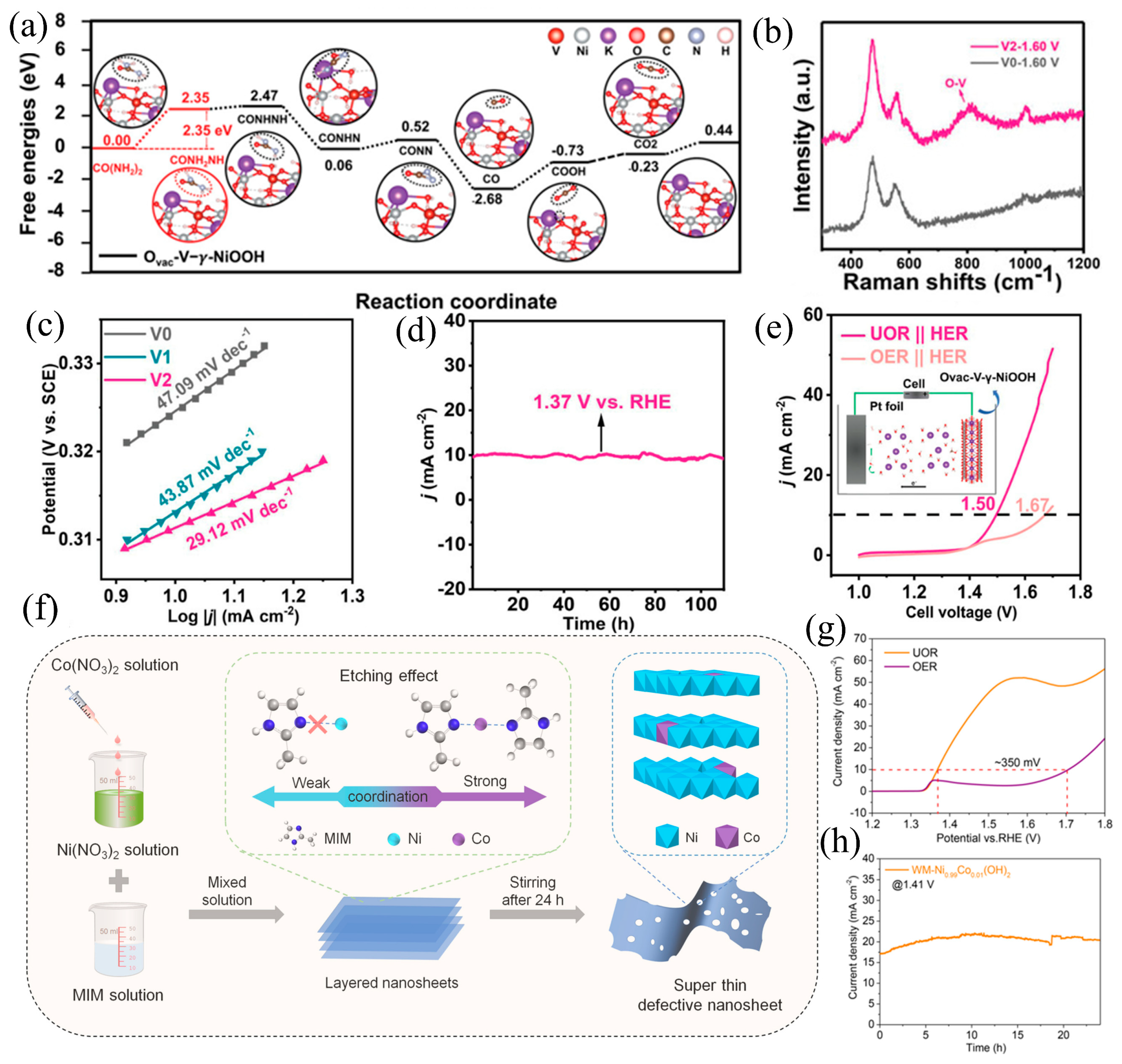
| Ovac-V-Ni(OH)2 | 1 M and 0.33 M | 1.47 (vs. RHE) | 100 mA cm−2 | 29.12 mV dec−1 | [82] |
| WM-Ni0.99Co0.01(OH)2 | 1 M and 0.33 M | 1.37 (vs. RHE) | 10 mA cm−2 | 31 mV dec−1 | [83] |
| Catalysts | KOH and Urea | Potential/V | Current Density | ECSA or Tafel Slope | Ref. |
|---|---|---|---|---|---|
| CoN/Ni(OH)2 | 1 M and 0.5 M | 1.39 (vs. RHE) | 50 mA cm−2 | 64 mV dec−1 | [89] |
| A-NiFeV/NF | 1 M and 0.33 M | 1.39 (vs. RHE) | 100 mA cm−2 | 34.8 mV dec−1 | [91] |
| hcp Ni/r-Ni(OH)2 | 1 M and 0.33 M | 1.36 (vs. RHE) | 100 mA cm−2 | 52.73 mV dec−1 | [92] |
Disclaimer/Publisher’s Note: The statements, opinions and data contained in all publications are solely those of the individual author(s) and contributor(s) and not of MDPI and/or the editor(s). MDPI and/or the editor(s) disclaim responsibility for any injury to people or property resulting from any ideas, methods, instructions or products referred to in the content. |
© 2024 by the authors. Licensee MDPI, Basel, Switzerland. This article is an open access article distributed under the terms and conditions of the Creative Commons Attribution (CC BY) license (https://creativecommons.org/licenses/by/4.0/).
Share and Cite
Zeng, Y.; Xiang, S.; Lu, S.; Qi, X. Structural Design of Nickel Hydroxide for Efficient Urea Electrooxidation. Materials 2024, 17, 2617. https://doi.org/10.3390/ma17112617
Zeng Y, Xiang S, Lu S, Qi X. Structural Design of Nickel Hydroxide for Efficient Urea Electrooxidation. Materials. 2024; 17(11):2617. https://doi.org/10.3390/ma17112617
Chicago/Turabian StyleZeng, Yi, Shouqin Xiang, Shun Lu, and Xueqiang Qi. 2024. "Structural Design of Nickel Hydroxide for Efficient Urea Electrooxidation" Materials 17, no. 11: 2617. https://doi.org/10.3390/ma17112617