Article

Oxidation Performance of Nano-Layered (AlTiZrHfTa)Nx/SiNx Coatings Deposited by Reactive Magnetron Sputtering

by
Djallel Eddine Touaibia
1,2,*,
Sofiane Achache
1,2,
Abdelhakim Bouissil
1,2,
Fabrice Parent
1,2,
Jaafar Ghanbaja
3,
Alina Gorbunova
4,
Pavel S. Postnikov
4,
Mohamed Mehdi Chehimi
5,
Frederic Schuster
6,
Frederic Sanchette
1,2 and
Mohamed El Garah
1,2,*
1
LASMIS—Laboratory of Mechanical & Materials Engineering, Antenne de Nogent-52, Pôle Technologique de Sud-Champagne, 52800 Nogent, France
2
LRC CEA-LASMIS, Nogent International Centre for Coating Innovation (NICCI), Pôle Technologique de Sud-Champagne, 52800 Nogent, France
3
Institut Jean Lamour (UMR CRS 7198), Université de Lorraine, 54000 Nancy, France
4
Research School of Chemistry and Applied Biomedical Sciences, Tomsk Polytechnic University, Tomsk 634050, Russia
5
ITODYS, CNRS, UMR 7086, University of Paris, 15 rue JA de Baïf, 75013 Paris, France
6
Commissariat à l’Energie Atomique et aux énergies Alternatives (CEA) Saclay, 91191 Gif-sur Yvette, France
*
Authors to whom correspondence should be addressed.
Materials 2024, 17(12), 2799; https://doi.org/10.3390/ma17122799
Submission received: 7 May 2024 / Revised: 1 June 2024 / Accepted: 4 June 2024 / Published: 7 June 2024
(This article belongs to the Special Issue Preparation of Thin Films by PVD/CVD Deposition Techniques)

Abstract

:
This work uses the direct current magnetron sputtering (DCMS) of equi-atomic (AlTiZrHfTa) and Si targets in dynamic sweep mode to deposit nano-layered (AlTiZrHfTa)Nx/SiNx refractory high-entropy coatings (RHECs). Transmission electron microscopy (TEM), field emission scanning electron microscopy (FESEM), thermogravimetric analysis (TGA), X-ray diffraction (XRD), and X-ray photoelectron spectroscopy (XPS) are used to investigate the effect of Si addition on the oxidation behavior of the nano-layered coatings. The Si-free nitride coating exhibits FCC structure and columnar morphology, while the Si-doped nitride coatings present a FCC (AlTiZrHfTa)N/amorphous-SiNx nano-layered architecture. The hardness decreases from 24.3 ± 1.0 GPa to 17.5 ± 1.0 GPa because of the nano-layered architecture, whilst Young’s modulus reduces from 188.0 ± 1.0 GPa to roughly 162.4 ± 1.0 GPa. By increasing the thickness of the SiNx nano-layer, kp values decrease significantly from 3.36 × 10⁻⁸ g2 cm−4 h−1 to 6.06 × 10⁻⁹ g2 cm−4 h−1. The activation energy increases from 90.8 kJ·mol−1 for (AlTiZrHfTa)Nx nitride coating to 126.52 kJ·mol−1 for the (AlTiZrHfTa)Nx/SiNx nano-layered coating. The formation of a FCC (AlTiZrHfTa)-Nx/a-SiNx nano-layered architecture results in the improvement of the resistance to oxidation at high temperature.

1. Introduction

The expanding strives for innovative materials—required to operate in demanding thermal and mechanical environments in industry—leads to several initiatives in academia and industry. The most crucial characteristics needed for protective coatings are high hardness, strong adherence to surfaces, high strength at high temperatures, and good oxidation resistance [1,2]. This is why innovative coatings with increased hardness, wear, and oxidation resistance are urgently required and should be studied. Binary system coatings such as TiN and CrN [3], ternary coatings such as CrAlN [4,5], multilayer coatings such as TiC/VC [6], TiAlN/CrN [7], TiN/Si3N4 [8], and other multilayer nano-composite coatings [9,10,11] have all been steadily investigated and used extensively. Multilayers showed interesting properties in terms of hardness, wear, and oxidation resistances [12,13,14,15,16].
The alloying concept of high-entropy alloys (HEAs), or multi-principal-element alloys, is believed to hold promise in this regard. Generally, HEAs are formed of at least five elements with atomic ratios varying from 5 to 35 at.%, characterized by a single-phased solid solution [17,18]. They have a high mixing entropy compared to conventional alloys in the solution state, allowing them to form stable solid solutions at high temperatures and inhibiting the formation of undesired brittle intermetallic compounds [19,20,21]. Hence, HEAs are considered as a potential class of materials for protective coatings [22,23,24,25].
Refractory high-entropy alloys (RHEAs) based on transition group metals have interesting applications in several devices [8,26,27]. However, they frequently exhibit room-temperature brittleness and poor oxidation resistance at elevated temperatures [28,29,30,31]. Several studies have been undertaken in the past to improve the oxidation resistance of refractory alloys through alloying additions containing metals such as Al, Cr, and Si. When introduced in an appropriate amount, these elements may stimulate the formation of protective oxide top-layers like: Al2O3, Cr2O3, and SiO2 [29,32,33,34].
The critical challenge for RHEAs is still high-temperature oxidation resistance. Muller et al. [35] enhanced the protective properties of TaMoCrTiAl RHEAs by alloying with Cr and Al. The combination of Al and Cr resulted in the development of adhering and protective CrTaO4 oxide scale. The CrTaO4 layer was formed in the 500–1200 °C temperature range. Sheikh et al. [29] performed an aluminizing process on the ductile Al0.5Cr0.5Nb0.5Ta0.5Ti0.5. They reported an improvement in the oxidation resistance of the coating at 800 °C.
According to the literature, adding silicon increases oxidation resistance at high temperatures [24,36]. Yu et al. [24] used magnetron sputtering technology to deposit (AlCrTiZrMo)-Six-N coatings with varying silicon contents and investigated its effect on the structure and properties of the coatings. The addition of silicon resulted in grain refinement of the microstructure due to the formation of nano-composite architecture (FCC (AlCrTiZrMo)N nano-crystallites encapsulated by the amorphous Si3N4 phases). Due to the increase in Si content in the coating, high hardness, and Young’s modulus were achieved at 28.5 GPa and 325.4 GPa, respectively. When the Si content exceeds 4.5 at.%, the hardness and Young’s modulus decreased, due to an excess of amorphous boundary phase in the coating.
Different multilayered coatings, such as (TiZrNbTaHf)N/MoN [37], (TiZrNbTaHf)N/WN [38] prepared by vacuum-arc deposition, AlCrRuTaTiZr/(AlCrRuTaTiZr)N [25] and AlCrMoNbZr/(AlCrMoNbZr)N [39,40], deposited by reactive magnetron sputtering, were investigated. They exhibit good corrosion resistance, interface stability and mechanical properties. These multi-layer high-entropy nitride ceramic coatings (HENCFs) offer tunable features and promise for use in tool coating materials [41].
The aim of this study is to depict the Si and the nano-layered architecture effects on the oxidation resistance enhancement of the (AlTiZrHfTa)Nx RHEC, obtained at RN2 = 10% with (RN2 = N2/(Ar + N2)). In fact, this work is performed in line with the previous study with a deep focus on (AlTiZrHfTa)Nx RHECs and the improvement of their oxidation resistance [42]. The FCC (AlTiZrHfTa)Nx/a-SiNx nano-layered coatings were deposited by reactive DCMS of equi-atomic (AlTiZrHfTa) and Si targets in dynamic sweep mode, to provide adjustable coating characteristics [43]. Furthermore, the microstructure evolution, the chemical composition, the structure, and the mechanical properties are also addressed.

2. Materials and Methods

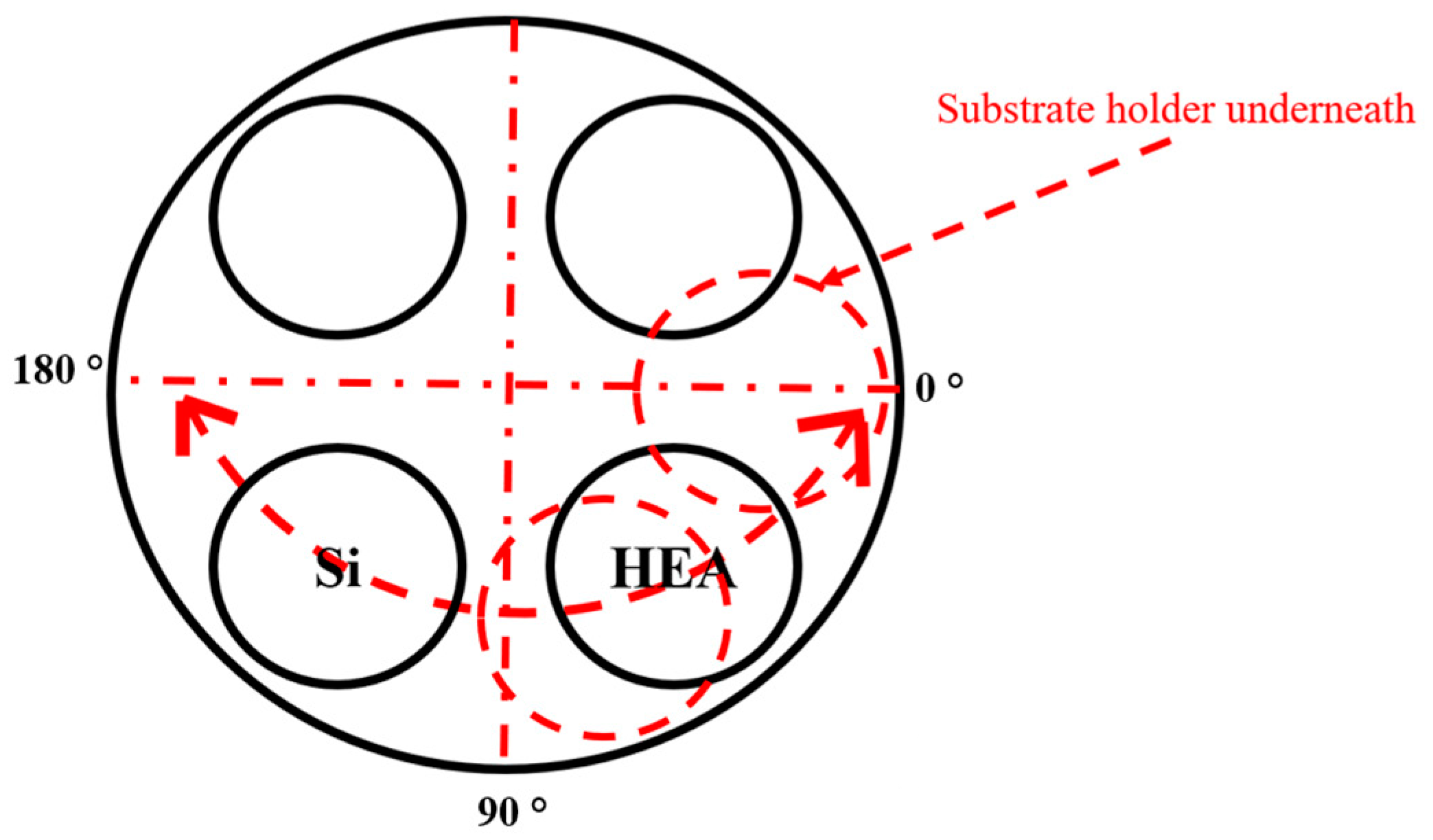
2.1. Deposition of the Coatings

The FCC (AlTiZrHfTa)Nx/a-SiNx RHECs were deposited by means of DP 650 Alliance Concept device (. The RHECs were deposited on different substrates: flat glass for X-ray diffraction (XRD) analysis, on Si (100) for scanning electron microscopy (SEM), electron probe micro-analysis (EPMA), and transmission electron microscopy (TEM) investigations, and (0 0 0 1)-oriented sapphires substrates for TGA. The co-deposition was carried out by reactive DCMS of 99.99% pure equi-atomic (AlTiZrHfTa) HEA and 99.99% (brazed) Si targets. Prior to loading into the reactor, the substrates were ultrasonically cleaned in acetone and ethanol. The distance between the targets and the substrate holder was 6 cm.
Before deposition, the targets were homogeneously sputtered by argon ions for 10 min at (1 Pa). Afterwards, the substrates’ surfaces were etched with argon ions (1 Pa) by RF power of 200 watts for a during 23 min. The HEA target current intensity was 1.0 A; however, the current intensity of Si target (ISi) varied from 0 A to 0.4 A. The coatings were deposited, at 1 Pa, under RN2 flow ratios of 10%. During deposition, a rotating substrate holder was used (rotating speed = 2 rpm), with a sweep mode (amplitude = 180 °), Figure 1. The deposition durations were adjusted to obtain at least 2 µm-thickness for all coatings.

2.2. Sample Analysis

2.2.1. Structure and Microstructure Characterization

The crystal phase identification was carried out by X-ray diffraction on the D8-Advance Bruker diffractometer (Bruker, Billerica, MA, USA) in Bragg–Brentano symmetrical mode, with a radiation source of Cu Kα (λ = 1.544184 Å, 40 kV, 40 mA), a scanning range of 20 ° to 100 ° with a step speed of 0.02 °/s. TEM studies of the coatings were carried out by using a JEM-ARM 200F cold Field Emission Gun (FEG) (JEOL, Tokyo, Japan) (TEM/Scanning Transmission Electron Microscopy STEM). The TEM instrument was running at 200 kV and equipped with an image corrector and a spherical aberration (Cs) probe (point resolution 0.12 nm in TEM mode and 0.078 nm in STEM mode). Focused Ion Beam/Scanning Electron Microscopy (FIB/SEM) FEI Helios NanoLab 600i (FEI, Hillsboro, OR, USA) with platinum Gas Injection System was used to prepare TEM samples. The chemical compositions of the (AlTiZrHfTa)Nx/a-SiNx RHECs were analyzed using EPMA (microprobe JEOL JXA-8530F, JEOL, Tokyo, Japan). The bonding structure of the nano-layered coatings was characterized by X-ray photoelectron spectroscopy using an NEXSA apparatus (Thermo, East Grinsted, UK) fitted with a monochromatic X-ray Al Kα source (energy = 1486.6 eV and power = 150 W).
A TESCAN MIRA Field emission source electron–Schottky electron gun was used to measure the thickness and examine the morphology of the coatings’ cross-sections and surfaces.

2.2.2. Mechanical Properties

The deposited high-entropy coatings’ nano-hardness (H) and reduced Young’s modulus (ER) were measured by using a HYSITRON, TI980 Triboindenter instrument (Bruker Nano, Inc, Eden Prairie, MN, USA) equipped with a Berkovitch indenter (Bruker Nano, Inc, Eden Prairie, MN, USA). To eliminate the effects of substrate stiffness, the maximum penetration depth is set to less than 10% of the coating thickness. The values of hardness and Young’s modulus were calculated by taking an average of thirty indents.

2.2.3. High-Temperature Oxidation Tests

A thermogravimetric analyzer (TGA, SETARAM, SETSYS evolution, (SETARAM Instrumentation KEP Technologies, Caluire-et-Cuire, France) was used to conduct the oxidation tests in a dry-air (80% N2, 20% O2) atmosphere. The (0 0 0 1)-oriented sapphires were dual-side coated and served as the test specimens for the TGA. Two different testing protocols were utilized: the first was dynamic and the second protocol was static; more details are provided in reference [42]. Both protocols are used to evaluate the oxidation resistance of the coatings and assess the effect of Si addition on the oxidation performances of the RHECs.

3. Results and Discussion

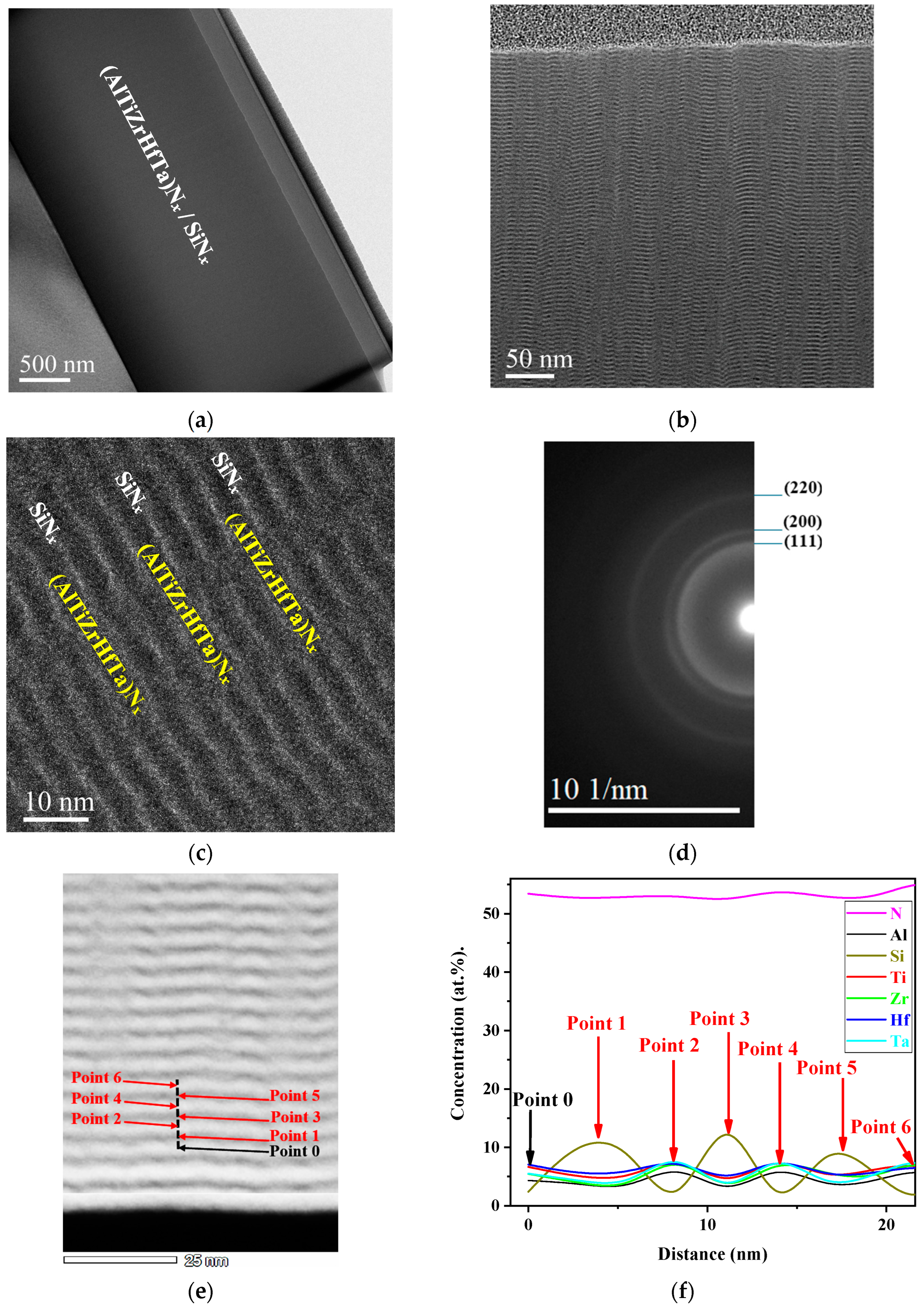
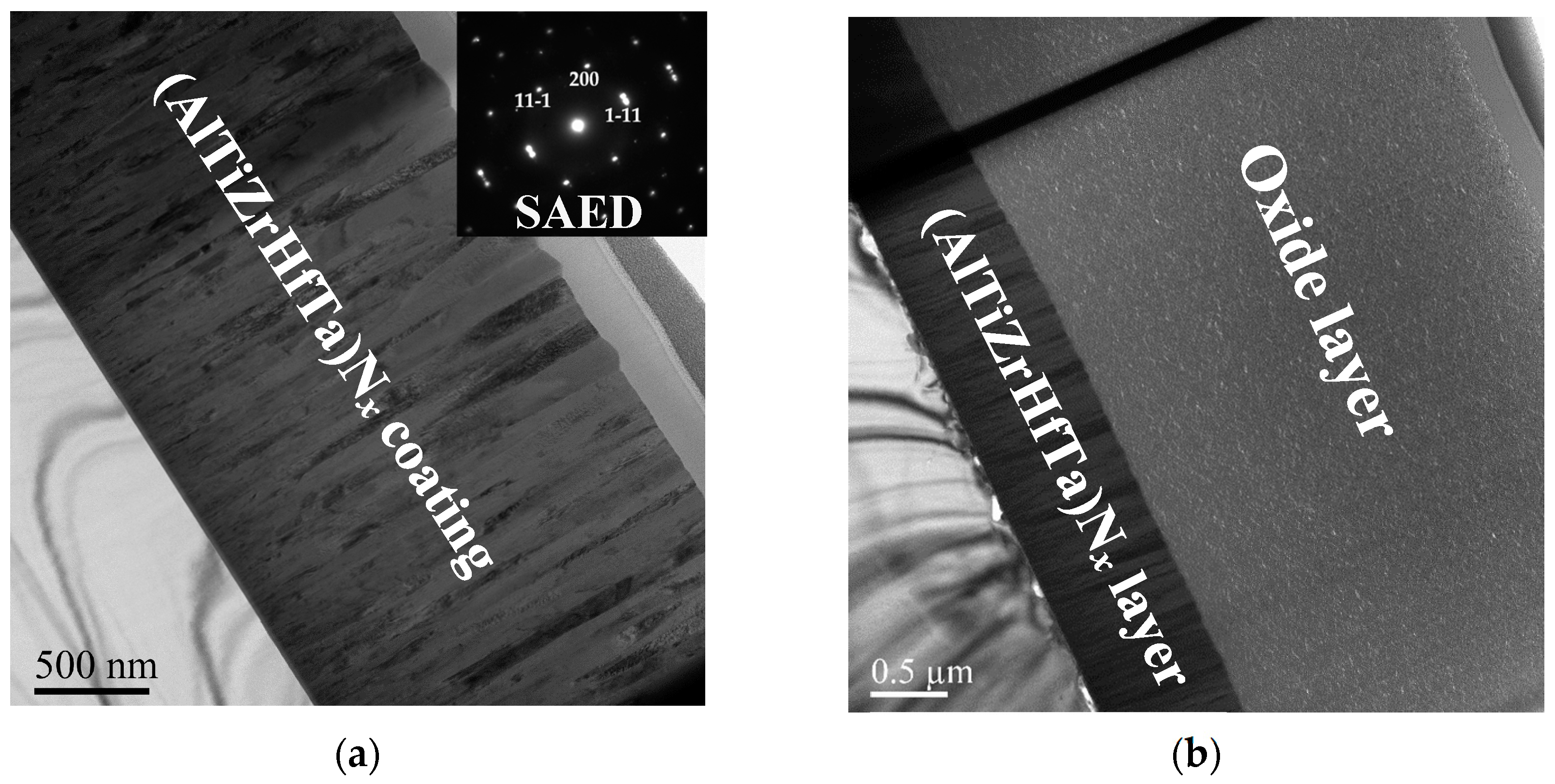
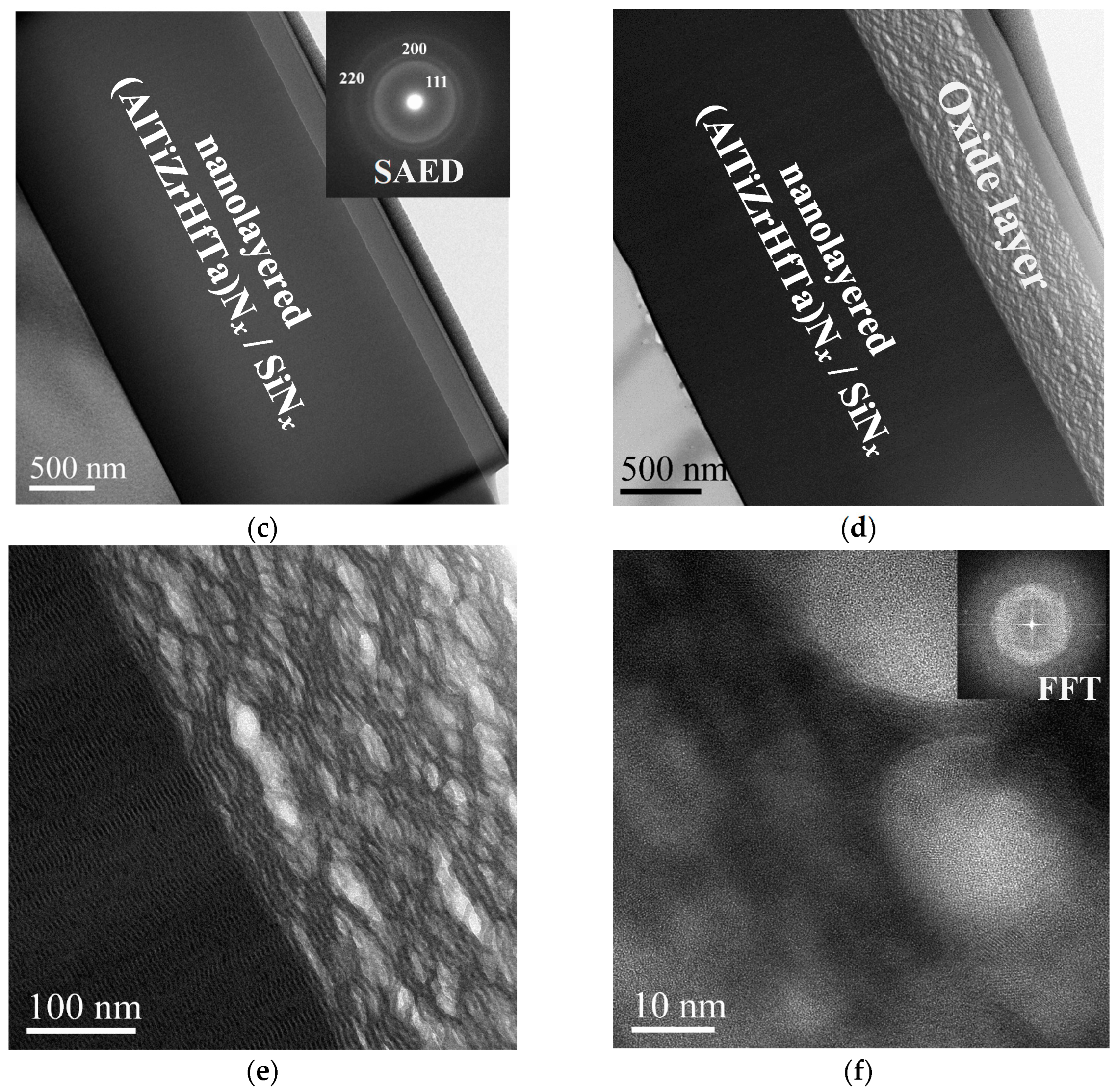
3.1. Microstructure of (AlTiZrHfTa)Nx/SiNx Thin Coatings

TEM investigations were performed on the selected samples of (AlTiZrHfTa)Nx nitride coating and high-entropy nitride coating obtained for ISi = 0.2 A. This latter coating presented a protective one of the best oxidation behavior (Section 3.6.2). Figure 2 presents the cross-sectional TEM bright field micrographs, and the selected area presents electron diffraction (SAED) patterns of the FCC (AlTiZrHfTa)Nx/amorphous SiNx obtained for ISi = 0.2 A. The HRTEM (high-resolution transmission electron microscopy) micrograph and compositional profile of (AlTiZrHfTa)Nx RHECs obtained for ISi = 0.2 A are also shown.
In the previous study [42], the results showed that the (AlTiZrHfTa)Nx nitride coating exhibits a stable FCC-single phased structure. In addition, the nitride coating features a coarse, fiber-like grain structure in the coating growth, as well as a V-shaped growth of faceted columns, indicating T zone pattern growth (Barna Model) [44]. (AlTiZrHfTa)Nx nitride presented a monolithic architecture.
When (AlTiZrHfTa)Nx/SiNx is deposited, the coating is denser (Figure 2a) compared to the (AlTiZrHfTa)Nx nitride coating, which has a columnar morphology [42]. For (AlTiZrHfTa)Nx/SiNx coating, obtained at ISi = 0.2 A, an obvious nano-layered structure was observed with clear interfaces between the Si–N nano-layer and (AlTiZrHfTa)Nx nano-layer (Figure 2b,c). The period α = t (AlTiZrHfTa)Nx + t SiNx layer, where t (AlTiZrHfTa)Nx and t SiNx are the thicknesses of the (AlTiZrHfTa)-Nx nano-layer and the SiNx nano-layer, was measured at around 5 nm with t(AlTiZrHfTa)N layer = 3.5 nm, and tSiNx layer = 1.5 nm (Figure 2c). A similar configuration was observed by Cai et al. [45] and Xu et al. [46] when investigating dual phase CoCrCuFeNi/Al nano-layered and TiAlN/TiN, TiAlN/ZrN nano-layered coatings, respectively. In our case, the nano-layered architecture is formed with a thinner period. During the process, the small target–substrate distance (6 cm) and a low sweep rate (2 rpm) made the substrates become exposed separately, for a certain duration, to each target.
The HRTEM image shows the presence of a nano-layered structure (Figure 2c). The SAED pattern, presented in Figure 2d, reveals that the SiNx nano-layer is amorphous and the (AlTiZrHfTa)Nx nano-layer is a clear FCC crystalline structure (Figure 2d). Furthermore, line-scan EDS profiles, illustrated in Figure 2e,f indicate clearly the presence of fluctuations in Si and (Al,Ti,Zr,Hf,Ta) concentrations between neighboring nano-layers, as well as a relatively stable N concentration profile. These indicates that (1) all elements are bounded with nitrogen and (2) the multilayer exists at nano-metric scale ((AlTiZrHfTa)Nx + SiNx).
The XPS technology has been used to identify the different bounding between the constituent elements of the RHECs. Our group has published the XPS spectra, where the full spectrum was shown, of the (AlTiZrHfTa)Nx coating for various nitrogen flow rates (RN2) [47,48]. In this work, we proceeded with the silicon bounding only and the results are presented in Figure 3. The Si 2p spectrum shows the presence of one peak at 101.8 eV that can be assigned to Si–N bonds in SiNx. Similar trend have been reported by Shi et al. [49] and Yu et al. [24], revealing the formation of a Si3N4 component. As the ISi increases, the thickness of the SiNx layer increases.

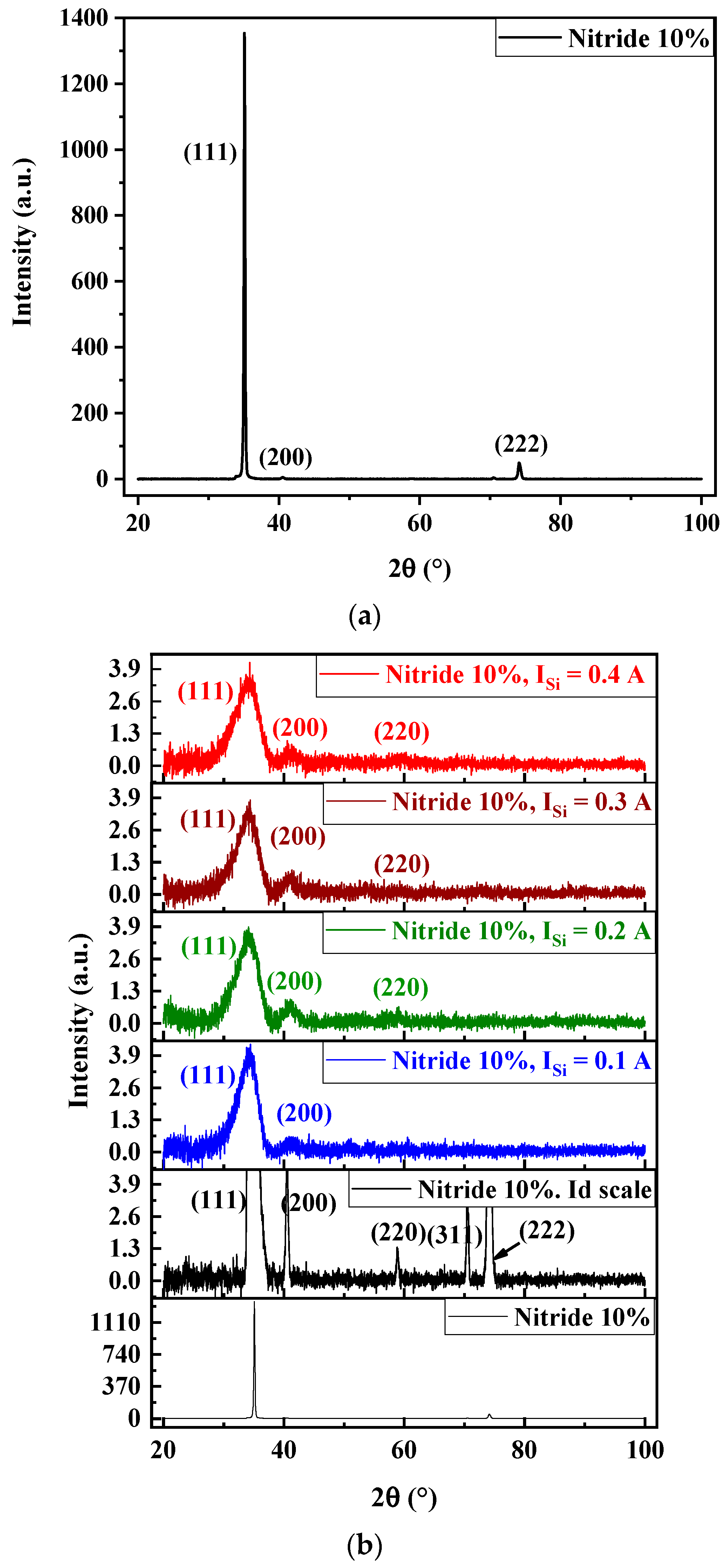
3.2. Structure and Microstructure

Figure 4 illustrates the XRD patterns of FCC (AlTiZrHfTa)Nx/a-SiNx RHECs as a function of ISi, for RN2 = 10%. The diffraction peaks were identified to TaN structure (CIF No. 2310957). The (AlTiZrHfTa)Nx (RN2 = 10%) nitride coating exhibits single-phased [NaCl-type (β1)] FCC solid solution structure (Figure 4a), rather than any complex phase separations [50,51,52]. This trend has been figured out in the previous studies [42,48] and observed in the literature as well, for several high-entropy thin coatings like: AlCrTaTiZr [52], AlCrMoSiTi [53], TiVCrZrHf [54], and TiTaZrHfW [55].
When (AlTiZrHfTa)Nx/SiNx coatings are deposited, XRD patterns (Figure 4b) show low-intensity and large diffraction peaks (Figure 4b), compared to that of nitride, which is directly linked to the formation the nano-layered architecture, alternating FCC (AlTiZrHfTa)Nx nano-layers and amorphous SiNx nano-layers as shown in (Section 3.1). In fact, the SiNx-based compound presents an amorphous aspect [8,50,56,57] and inhibits the growth of the nitride columns [8,58], resulting in the broadening of the peaks when depositing (AlTiZrHfTa)Nx/SiNx.
The average grain size (Ø) is calculated from the most intense (111) peaks, by using the Scherrer equation [59]. The mean grain size values decreased from 45.92 nm for FCC (AlTiZrHfTa)-Nx coating to ~2 nm for all the FCC (AlTiZrHfTa)-Nx/a-SiNx coatings (Table 1).
However, according to the comprehensive research so far, at room temperature, refractory metal nitrides deposited on substrates require some time to achieve a high-crystalline structure [42,54,55,60]. Nieborek et al. [61] observed that the grain size of the magnetron sputtered TiN increases as the coating grows. They clearly showed (Figure 7d in reference [61]) that at the interface between TiN film and the substrate, the coating is almost amorphous. The grains with small size (almost amorphous) can be found at the interface with the substrate, and as the coating becomes thicker, the grain size increases, reaching its maximum near the surface. In this study, the deposition of SiNx resumes crystallization and renders all layers nearly amorphous. That is why there is a direct drop in the average grain size after the introduction of the SiNx layer and no dependence on the SiNx layer thickness (Table 1). The further increase in ISi could lead to the increase in the deposition rate, which leads to the increase in the thickness of the SiNx nano-layer.

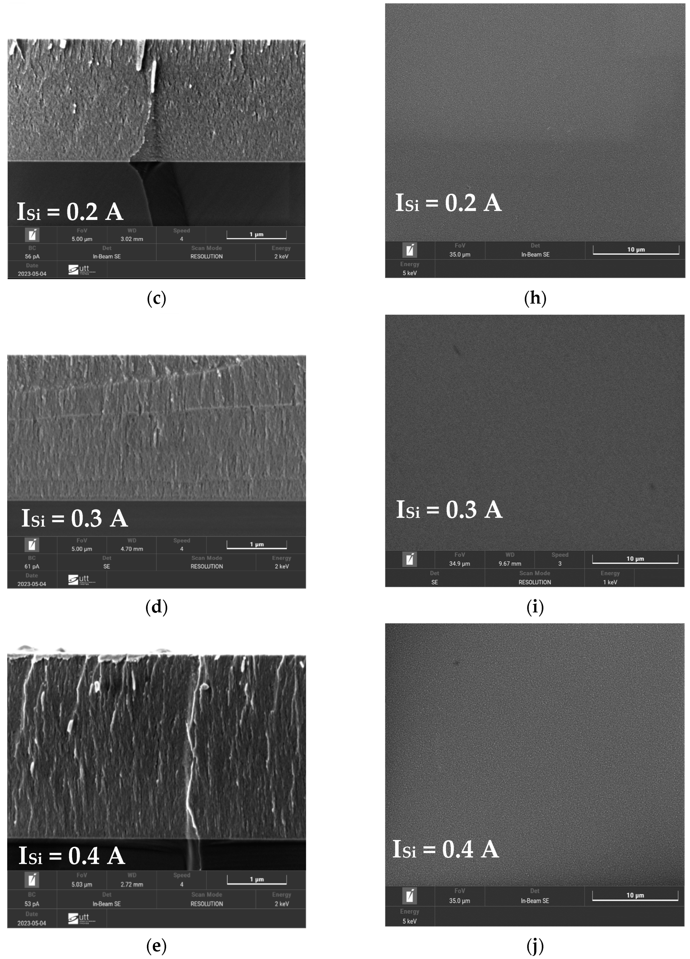
3.3. Morphology of FCC (AlTiZrHfTa)Nx/a-SiNx Thin Coatings

The cross-sectional and top view SEM micrographs of the FCC (AlTiZrHfTa)Nx/a-SiNx RHECs with various ISi are shown in Figure 5. As we can notice from the figure, the coatings have a good combination with the silicon substrate. No obvious defects have been observed.
For the (AlTiZrHfTa)Nx nitride coating (Figure 5a), large columnar morphology throughout the coating is observed, while the surface presents a pyramid-like aspect (Figure 5f). However, when FCC (AlTiZrHfTa)Nx/a-SiNx is deposited, the coatings exhibit a dense, smooth cross-sectional morphology and no obvious columnar growth (Figure 5b–e). This aspect is linked to the formed nano-layered architecture, illustrated in Figure 2b, during the coating growth. As illustrated in Table 1 above, the calculated mean grain size decreases with the introduction of Si. This trend reflects the grain growth inhibition by the amorphous SiNx nano-layer [8,57,58].

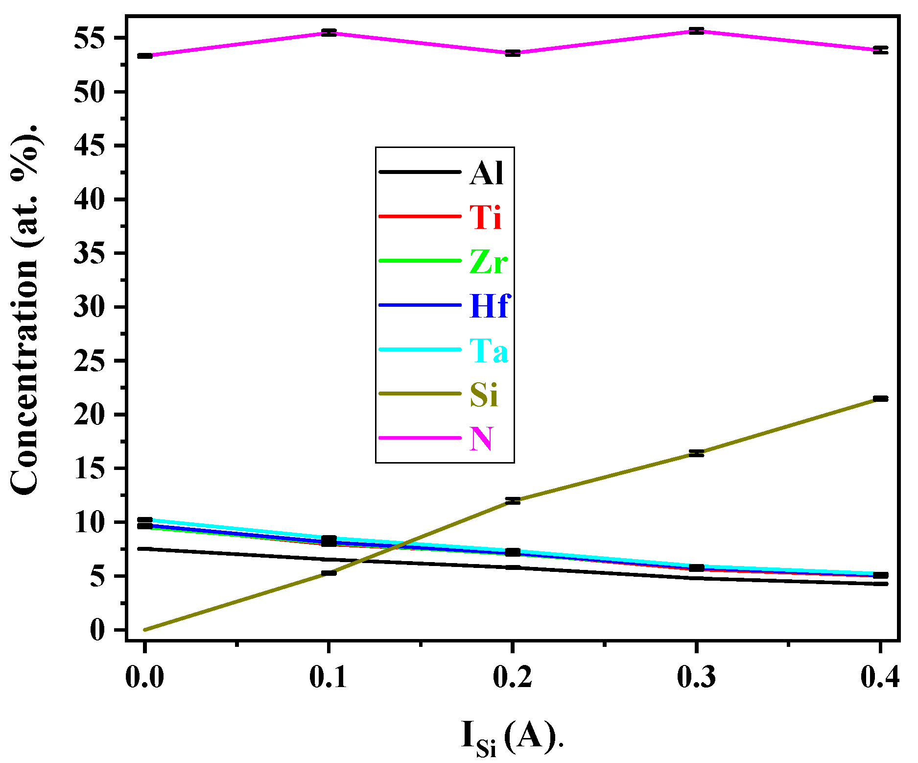
3.4. Chemical Composition

Figure 6 presents the EPMA-detected global composition of (AlTiZrHfTa)Nx/SiNx RHECs deposited at RN2 = 10%. The increase in silicon percentage in RHECs along with the increase in ISi suggest that the newly added element may be effectively incorporated into the nitride layer as expected.
The chemical composition of the (AlTiZrHfTa)Nx coating is as follows: Al = 7.5 at.%, Ti = 9.7 at.%, Zr = 9.5 at.%, Hf = 9.7 at.%, Ta = 10.3 at.%, and N = 53.3 at.%. The amount of Al was shown to be low in comparison to the target content (20 at.%). This phenomenon was explained in reference [42]. The composition stabilization of N content in the high-entropy nitride at RN2 = 10% is associated with the stabilization of the crystalline nitride solid solution and target poisoning [62].
As ISi increased from 0.1 A to 0.4 A, the atomic percentage of Si in the FCC(AlTiZrHfTa)Nx/a-SiNx deposited coatings raises from 5.3 at.% to 21.5 at.%, respectively (Table 2). Moreover, the contents of metals slightly decrease, resulting from the increase in silicon percentage and the formation of nitride structure.

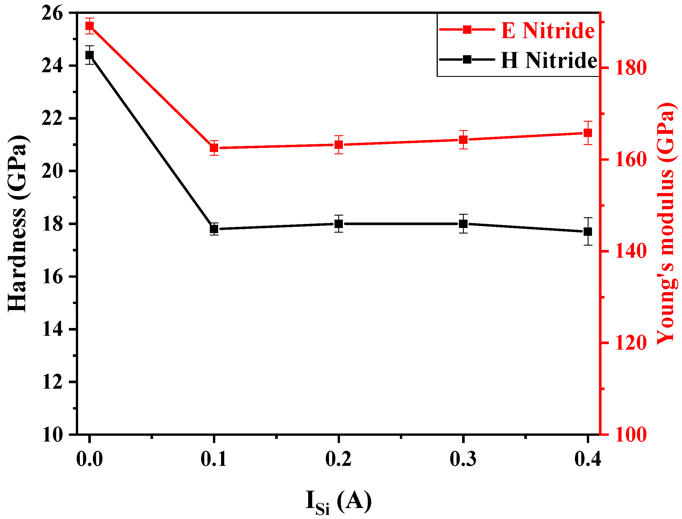
3.5. Mechanical Properties

Hardness and Young’s Modulus of FCC(AlTiZrHfTa)Nx/a-SiNx Thin Coatings

Figure 7 depicts the evolution of hardness (H) and Young’s modulus (E) of FCC (AlTiZrHfTa)Nx/a-SiNx (RN2 = 10%) coatings as a function of ISi. H decreased from 24.4 ± 0.3 GPa to 17.7 ± 0.5 GPa, while the Young’s modulus also decreased from 189.0 ± 1.7 GPa to around 162.5 ± 1.6 GPa. This is due to the formation of a nano-layered architecture (amorphous SiNx nano-layers and FCC crystalline (AlTiZrHfTa)Nx nano-layers). The amorphous nano-layer (SiNx) hinders the growth of (AlTiZrHfTa)Nx crystallites, leading to a sudden orientation drop as revealed in XRD patterns (cf. Figure 4) [63].
In general, nano-layered architecture leads to the hardness enhancement of the coating due to the blocking of dislocation movements at interfaces [57]. For example TiN/Si3N4 multilayers exhibited a hardness enhancement with Si3N4 layer thickness less than 1 nm (about 0.5 or 0.7 nm) [64,65]. However, Dong et al. [66] reported a change in hardness trend as a function of Si3N4 layer thickness for ZrN/Si3N4 nano-layered coating. Indeed, when the Si3N4 layer thickness is about 0.6 nm, the hardness is increased, due to the formation of a crystallized Si3N4 nano-layer forming coherent interfaces with the ZrN layer. However, when the thickness exceeds 1.1 nm, an amorphous growth of Si3N4 is observed, resulting in a significant hardness decrease. In our study we can consider that the non-isostructural nano-layered coating associated with the amorphous SiNx with a thickness of 1.5 nm leads to a decline of mechanical properties. Similar trends have been observed for nano-layered coatings like Cr2N/Si3N4 [67], HfN/Si3N4 [68], and NbN/Si3N4 [69].

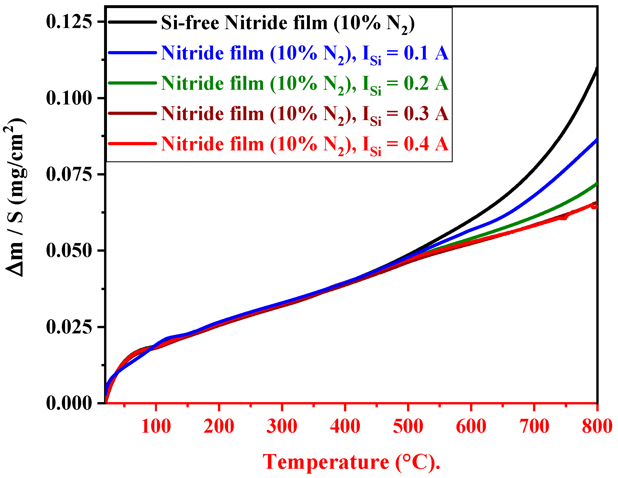
3.6. High-Temperature Oxidation Property

3.6.1. Oxidation Resistance of FCC(AlTiZrHfTa)Nx/a-SiNx Coatings

Figure 8 depicts the dynamic thermogravimetric analysis (TGA) curves of the FCC (AlTiZrHfTa)Nx and FCC (AlTiZrHfTa)Nx/a-SiNx coatings from room temperature (RT) to 800 °C. The weight gain of the FCC (AlTiZrHfTa)Nx coating (Figure 8) grows steadily between RT and 694 °C, followed by a rapid growth at higher temperatures. When the FCC (AlTiZrHfTa)Nx/a-SiNx RHECs are deposited, the weight gain shows a drastic growth only after around 703 °C (for the RHECs obtained for ISi = 0.1 A) but is largely lower than that of the FCC (AlTiZrHfTa)Nx coating. When the Si content increases further, the critical oxidation temperature exceeds 800 °C.

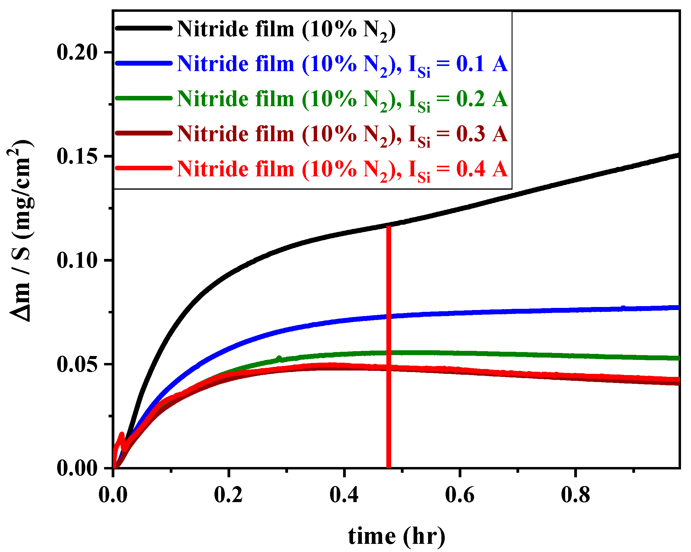
3.6.2. Oxidation Kinetics of FCC(AlTiZrHfTa)Nx/a-SiNx Coatings

Figure 9 illustrates the isothermal thermogravimetric curves plotted during 1 h of exposure at 800 °C for FCC (AlTiZrHfTa)Nx/a-SiNx coatings obtained for various ISi.
In the case of (AlTiZrHfTa)Nx nitride coatings, there is an initial slower parabolic weight gain growth up to 0.112 mg/cm2, followed by a quick linear increase after around 28 min of oxidation. The linear rate law following by the parabolic growth (Figure 9) is related to breakaway oxidation effect. The linear weight gain is assumed to represent a change in the scale structure by formation of thick, porous oxide scale promoting a significant access of gaseous species towards the coating phase [70]. Gorr et al. [71] noticed a similar variation for the NbMoCrTiAl-1Si arc melted HEA.
When FCC (AlTiZrHfTa)Nx/a-SiNx is deposited, the weight gain is drastically decreased. In addition, the breakaway point completely disappeared, which could be explained by the protectiveness enhancement of the new formed oxide [70,72].

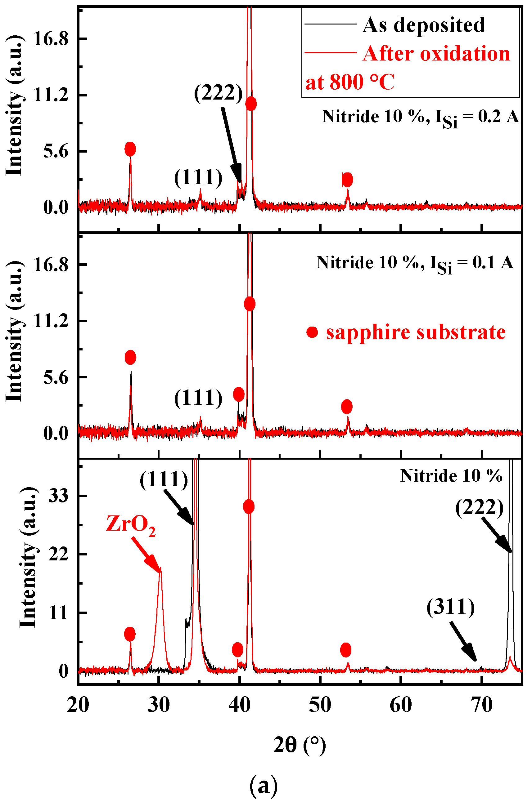
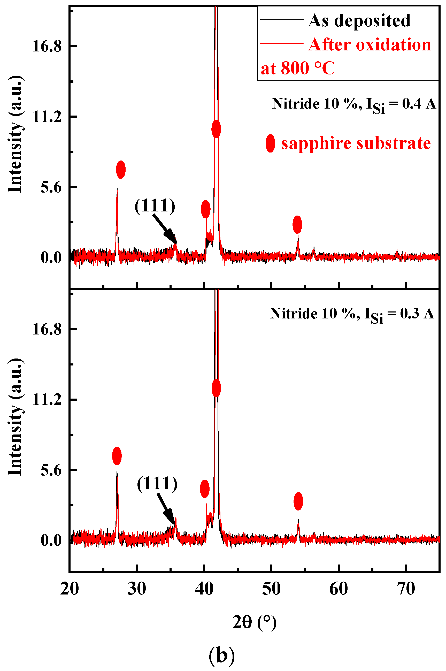
Structure Analysis of Oxidized FCC(AlTiZrHfTa)Nx/a-SiNx Coatings

Figure 10 presents the XRD patterns of (AlTiZrHfTa)Nx/a-SiNx RHECs before and after 1 h of isothermal oxidation at 800 °C in a dry-air atmosphere. After oxidation, we noted a presence of a peak at 2 ≈ 30°, which could be identified as zirconia (ZrO2). In addition, a broadening of (111) and (222) peaks occur after oxidation. This broadening could be attributed to the formation of oxides [55,73]. For the (AlTiZrHfTa)Nx/a-SiNx RHECs, no significant changes have been observed on XRD patterns whatever the current intensity on the Si target. At this stage, this analysis is not able to identify the oxide nature (complementary TEM and SEM results are presented below). It should be noted that neither peeling nor coating removal was observed on the annealed samples.

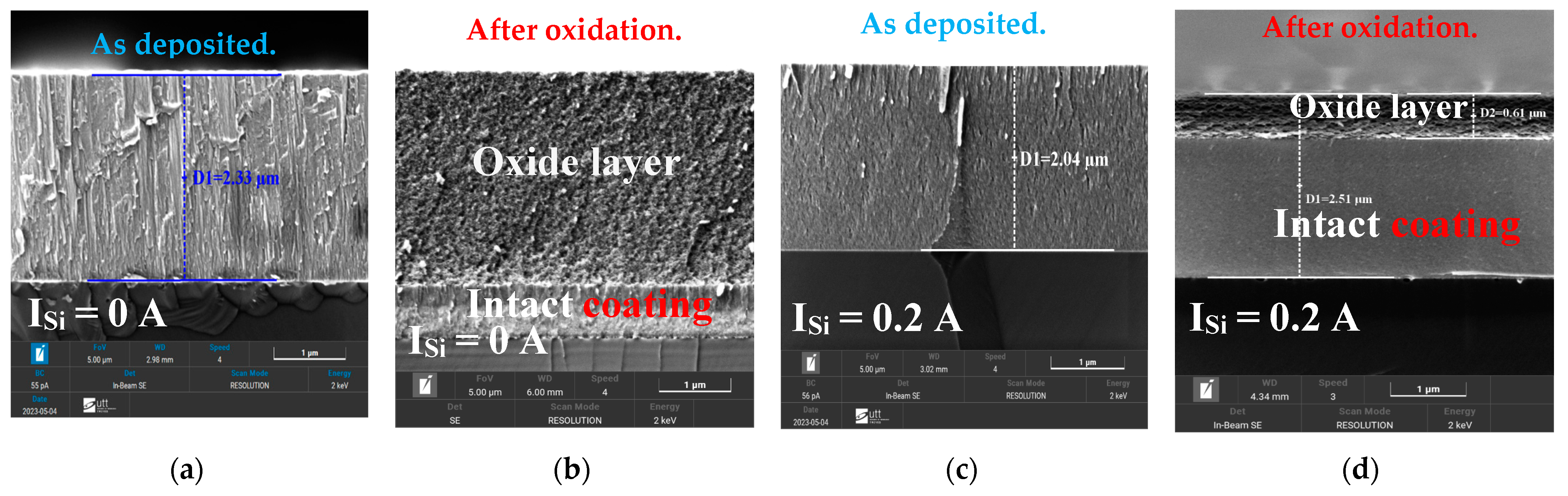
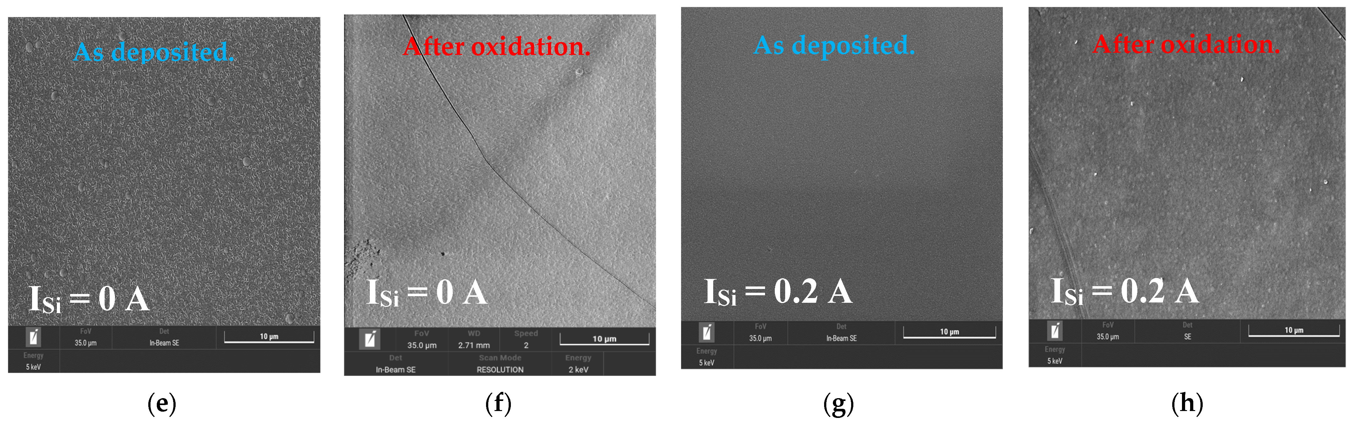
Morphology Analysis of Oxidized FCC(AlTiZrHfTa)Nx/a-SiNx Coatings

To better understand of the evolution of the morphology of (AlTiZrHfTa)Nx/a-SiNx RHECs following the oxidation process, SEM was used to investigate (AlTiZrHfTa)Nx and FCC (AlTiZrHfTa)Nx/a-SiNx obtained for ISi = 0.2 A. Figure 11 shows their surface and cross-sectional morphologies, after 1 h of isothermal oxidation at 800 °C in a dry-air atmosphere. Figure 11f,h clearly illustrates the presence of cracks and pores on the coating’s surfaces. In the case of the FCC (AlTiZrHfTa)Nx/a-SiNx coatings, obtained for ISi = 0.2 A, the oxide layer is thinner, which indicates a better oxidation resistance compared to (AlTiZrHfTa)Nx coatings (cf. Figure 9).

Microstructure Investigation of Oxidized FCC(AlTiZrHfTa)Nx/a-SiNx RHECs

The cross-sectional microstructure of oxidized (AlTiZrHfTa)Nx RHECs at RN2 = 10% and the (AlTiZrHfTa)Nx/a-SiNx coating obtained for ISi = 0.2 A was analyzed by using TEM (Figure 12). The as-deposited (AlTiZrHfTa)Nx nitride coating exhibits a columnar growth (Figure 12a) with (111) preferred orientation as shown by the inset SAED pattern. After oxidation, the (AlTiZrHfTa)Nx nitride coating reveals two separate zones: an intact coating with black contrast at the bottom and a homogeneous thick (≈2.5 μm, Figure 11b) and porous oxide layer on the top (depicted in reference [42]). For FCC (AlTiZrHfTa)Nx/a-SiNx coating, obtained for ISi = 0.2 A, a nano-layered architecture is observed (cf. Figure 2b). After oxidation of the (AlTiZrHfTa)Nx/SiNx coating, two different zones are observed as well: intact coating with a nano-layered architecture at the bottom (Figure 12e) and a homogeneous thin (≈600 nm) and porous oxide layer on the top (Figure 12d,e).
HRTEM image of the oxide of the (AlTiZrHfTa)Nx/SiNx coating, obtained for ISi = 0.2 A, is presented in Figure 12f. The oxide layer exhibits an amorphous aspect. This is further verified by the corresponding FFT pattern, which shows a circular diffuse ring (Figure 11f).
STEM-EDS mapping of the FCC (AlTiZrHfTa)Nx/a-SiNx coating obtained for ISi = 0.2 A, before and after the oxidation process on the oxidized zone area, was performed. The results are presented in the (Figure 13).
After 1 h of oxidation at 800 °C, we found a uniform distribution of metallic elements throughout the (AlTiZrHfTa)Nx/SiNx RHECs and oxide layer (Figure 13). As a result, a mixed oxide is formed [74]. It should be noted that the amorphous aspect of the oxide layer has also been observed for the (AlTiZrHfTa)Nx nitride coating [42].

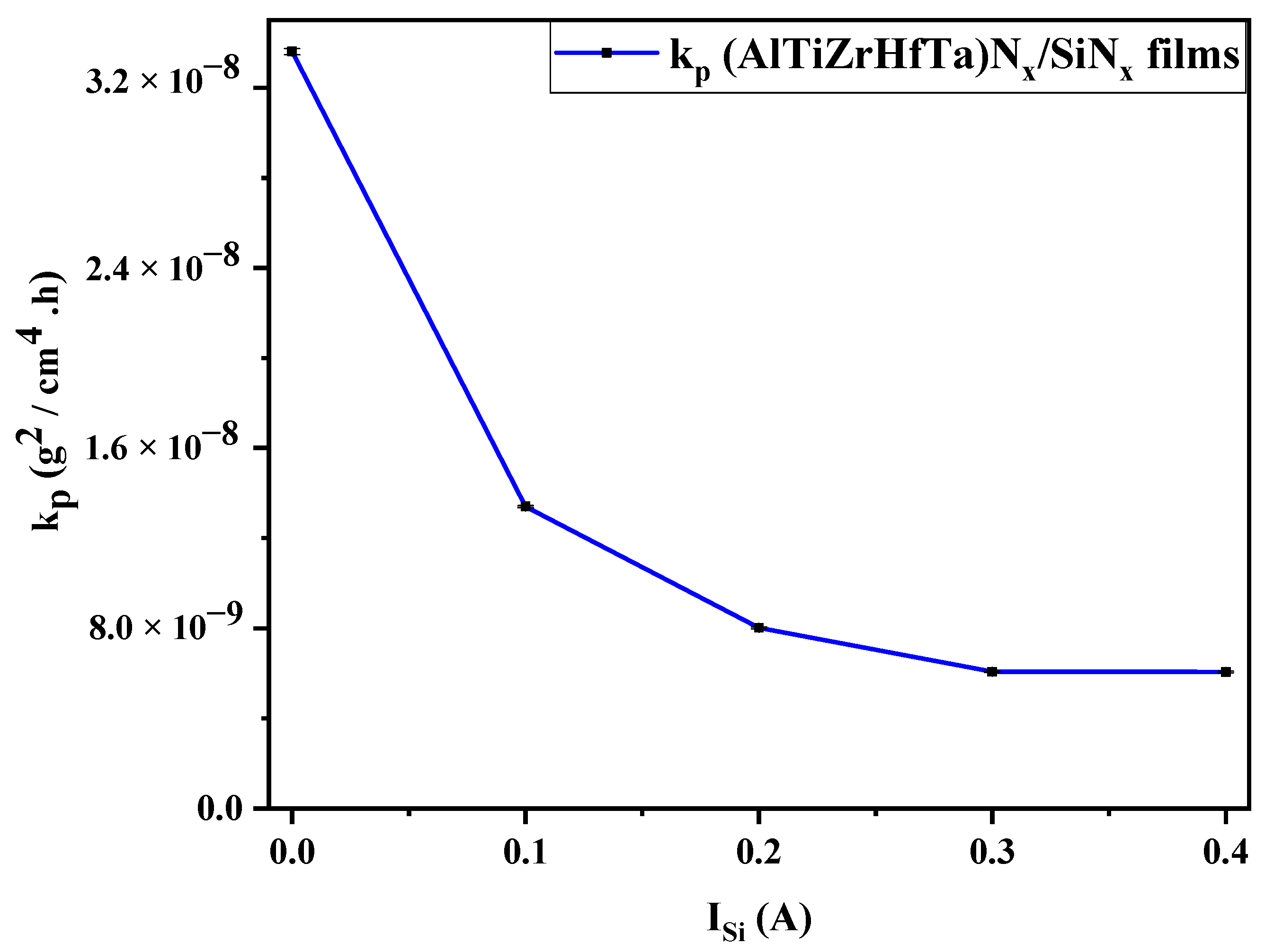
Oxidation Rate through kp Analysis

Figure 14 traces the parabolic rate constant kp g2 cm−4 h−1 at 800 °C for the investigated (AlTiZrHfTa)Nx and (AlTiZrHfTa)Nx/SiNx coatings. kp is calculated according to (Equation (1)) [75]. For the (AlTiZrHfTa)Nx coating, kp is calculated at 3.36 × 10⁻⁸ g2 cm−4 h−1 for the sample tested at 800 °C. However, in the case of the (AlTiZrHfTa)Nx/SiNx coating, obtained for ISi = 0.2 A, the kinetic constant kp decreased to 6.06 × 10⁻⁹ g2 cm−4 h−1 (Figure 14). This decreasing tendency sustains the previous oxidation kinetic curves’ evolution (cf. Figure 9), revealing an oxidation resistance enhancement of the (AlTiZrHfTa)Nx/SiNx coating compared to the (AlTiZrHfTa)Nx coating.
( Δ m S ) 2 = k p · t ,

Activation Energy Ea

The oxidation activation energy (Ea) is of fundamental importance to understanding the oxidation mechanisms. It can be evaluated from the Arrhenius formula (Equation (2)) [76], by linear fitting of the kinetic constant (oxidation rate) at different oxidation temperatures (700 °C, 750 °C, and 800 °C):
k p = k p 0   exp   ( E a R   T ) ,
R: molar gas constant, kp0: oxidation rate constant, and T: temperature.
The activation energy of (AlTiZrHfTa)Nx nitride coating was equal to 90.8 kJ·mol−1 [42]. However, the activation energy increases to a value of 126.52 kJ·mol−1 for the (AlTiZrHfTa)Nx/SiNx coating obtained for ISi = 0.2 A (Table 3). Even at this oxidation enhancement, the values remain low when compared to those of other alloys, as shown in Table 3.

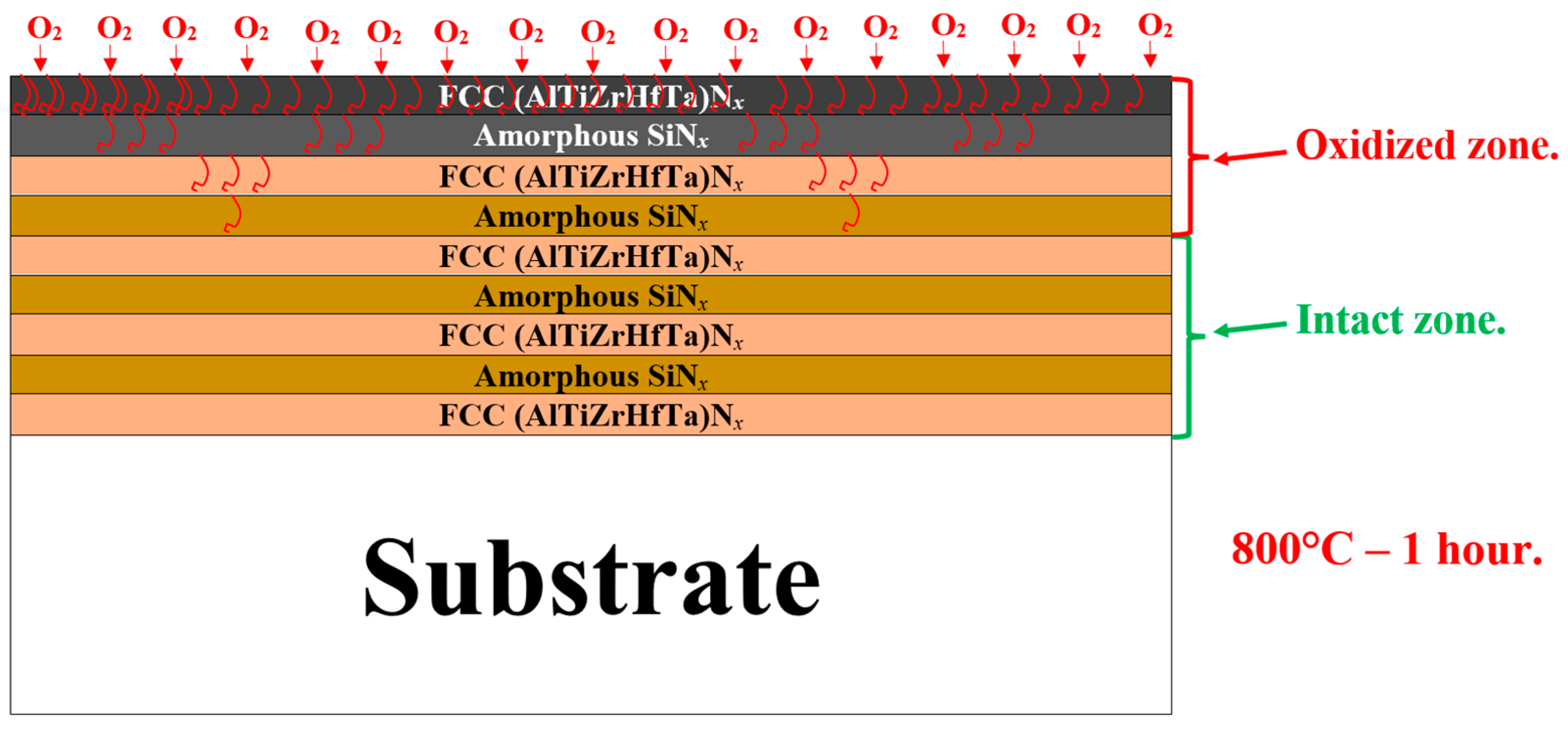
3.6.3. Discussion of the Oxidation Mechanisms

The present study explored the oxidation resistance of FCC (AlTiZrHfTa)Nx/SiNx thin coatings. When Si is introduced, the oxidation resistance is drastically enhanced, according to various parameters such as the increase in oxidation temperature, breakaway disappearance, on weight gain curve, and kp decreasing trend during 1 h of oxidation at 800 °C (cf. Figure 8, Figure 9 and Figure 14). SEM and TEM analyses illustrated the formation of a dense nano-layered architecture due to the sweeping mode during the deposition process. Moreover, XPS and XRD patterns depicted the presence of FCC (AlTiZrHfTa)Nx and amorphous SiNx phases.
It should be mentioned that the amorphous (SiNx) layer is known for its elevated resistance to oxygen diffusion at high temperatures [56,66,79,80]. Moreover, the oxidation rate decrease could also be related to a relatively smaller residual stress throughout the coating, as a result of multiple interfaces between the formed nano-layers [36,81,82,83]. This phenomenon differs significantly from monolithically grown (AlTiZrHfTa)Nx’s oxidation behavior (Figure 9 and Figure 11). In addition, the high number of interfaces of FCC (AlTiZrHfTa)N/a-SiNx nano-layers lead to a reduction in the interconnection of pores and defects penetrating through the coating that may result in oxygen diffusion into the oxidized coating [83].
A schematic model is proposed in Figure 15 to illustrate the SiNx inhibiting effect, when the (AlTiZrHfTa)Nx/a-SiNx thin coating is exposed to oxygen. Because of their amorphous nature, SiNx nano-layers act as barrier layers (shields), which could inhibit the mutual diffusion of additional metallic atoms and decreases the oxidation reaction [36]. Steyer et.al [84] showed the oxidation resistance enhancement of TiN coating by the segregation of amorphous SiNx at the grain boundaries, leading to an increase in the protective shielding effect. The results reported in this study verified that a coating synthesized by the current alloy design efficiently slowed the oxidation rate.

4. Conclusions

(AlTiZrHfTa)Nx/SiNx RHECs were synthesized by DCMS in two nitrogen ratios (RN2 = 0% and 10%).
The effect of Si’s addition on the structure, microstructure, mechanical properties, and oxidation behavior were investigated. The current study is mainly focused on the oxidation resistance enhancement of these so-called “refractory” HEA coatings by using an alloying approach and promoting nano-layered architecture.
  • The deposition of nano-layered FCC (AlTiZrHfTa)Nx/a-SiNx coatings results in a density increase in the nitride coatings.
  • The deposition of the nano-layered FCC (AlTiZrHfTa)Nx/a-SiNx coatings leads to the decrease in hardness and Young’s modulus up to H = 17.7 ± 0.5 GPa and E = 162.5 ± 1.6 GPa. The softening of the coatings results from the formation of the amorphous SiNx nano-layers, hindering the growth of the FCC (AlTiZrHfTa)Nx nano-layers.
  • The deposition of the nano-layered FCC (AlTiZrHfTa)Nx/a-SiNx coating improved the oxidation resistance at 800 °C. The increase in ISi significantly decreased the parabolic rate constant kp from 3.36 × 10⁻⁸ g2 cm−4 h−1 for FCC (AlTiZrHfTa)Nx coating to 6.06 × 10⁻⁹ g2 cm−4 h−1 for FCC (AlTiZrHfTa)Nx/a-SiNx coatings at 800 °C.
  • The activation energy Ea has increased from 90.8 kJ·mol−1 for the FCC (AlTiZrHfTa)Nx coating to 126.52 kJ·mol−1 for the FCC (AlTiZrHfTa)Nx/a-SiNx coating obtained for ISi = 0.2 A. This trend reflects an oxidation resistance improvement due to the formation of the amorphous SiNx nano-layer in alternance with FCC (AlTiZrHfTa)Nx.
The deposition of FCC (AlTiZrHfTa)Nx/a-SiNx results in the formation of an inhibiting amorphous SiNx nano-layer, protecting FCC (AlTiZrHfTa)Nx crystallites from oxygen onslaught, thus improving their oxidation resistance.
The results obtained in this study illustrate the effectiveness of using an alloying approach to further enhance the RHEAs’ efficiency, particularly toward high-temperature applications.

Author Contributions

Conceptualization, D.E.T., F.S. (Frederic Sanchette) and M.E.G.; methodology, D.E.T., S.A., F.S. (Frederic Sanchette) and M.E.G.; validation, D.E.T., S.A., F.S. (Frederic Sanchette) and M.E.G.; formal analysis, D.E.T., A.B., J.G. and A.G.; investigation, D.E.T., A.B., J.G., A.G., P.S.P. and M.M.C.; resources, F.P.; data curation, D.E.T., P.S.P., M.M.C. and M.E.G.; writing—original draft preparation, D.E.T.; writing—review and editing, D.E.T., S.A., A.B., F.S. (Frederic Sanchette) and M.E.G.; visualization, D.E.T., F.P., F.S. (Frederic Schuster), F.S. (Frederic Sanchette) and M.E.G.; supervision, F.S. (Frederic Sanchette) and M.E.G.; project administration, F.S. (Frederic Schuster); funding acquisition, F.S. (Frederic Schuster) and F.S. (Frederic Sanchette). All authors have read and agreed to the published version of the manuscript.

Funding

This research was funded by Le Groupement d’Intérêt Public Haute-Marne—GIP52 (no number), and La Direction du programme Transversal de compétences Matériaux et Procédés of Commissariat à l’Energie Atomique et aux énergies alternatives (CEA) (no number).

Institutional Review Board Statement

Not applicable.

Informed Consent Statement

Not applicable.

Data Availability Statement

The raw data supporting the conclusions of this article will be made available by the authors on request.

Acknowledgments

The authors thank the Université de Technologie de Troyes (UTT) and the central laboratories of TPU (Analytical Center) for the XPS measurements.

Conflicts of Interest

The authors declare no conflicts of interest.

References

  1. Holleck, H. Material Selection for Hard Coatings. J. Vac. Sci. Technol. A 1986, 4, 2661–2669. [Google Scholar] [CrossRef]
  2. Sundgren, J.-E.; Hentzell, H.T.G. A Review of the Present State of Art in Hard Coatings Grown from the Vapor Phase. J. Vac. Sci. Technol. A 1986, 4, 2259–2279. [Google Scholar] [CrossRef]
  3. Panjan, P.; Navinšek, B.; Cvelbar, A.; Zalar, A.; Milošev, I. Oxidation of TiN, ZrN, TiZrN, CrN, TiCrN and TiN/CrN Multilayer Hard Coatings Reactively Sputtered at Low Temperature. Thin Solid Film. 1996, 281–282, 298–301. [Google Scholar] [CrossRef]
  4. Barshilia, H.C.; Selvakumar, N.; Deepthi, B.; Rajam, K.S. A Comparative Study of Reactive Direct Current Magnetron Sputtered CrAlN and CrN Coatings. Surf. Coat. Technol. 2006, 201, 2193–2201. [Google Scholar] [CrossRef]
  5. Uchida, M.; Nihira, N.; Mitsuo, A.; Toyoda, K.; Kubota, K.; Aizawa, T. Friction and Wear Properties of CrAlN and CrVN Films Deposited by Cathodic Arc Ion Plating Method. Surf. Coat. Technol. 2004, 177–178, 627–630. [Google Scholar] [CrossRef]
  6. Zhang, H.; Zou, Y.; Zou, Z.; Wu, D. Microstructures and Properties of Low-Chromium High Corrosion-Resistant TiC–VC Reinforced Fe-Based Laser Cladding Layer. J. Alloys Compd. 2015, 622, 62–68. [Google Scholar] [CrossRef]
  7. Choi, P.-P.; Povstugar, I.; Ahn, J.-P.; Kostka, A.; Raabe, D. Thermal Stability of TiAlN/CrN Multilayer Coatings Studied by Atom Probe Tomography. Ultramicroscopy 2011, 111, 518–523. [Google Scholar] [CrossRef] [PubMed]
  8. Barshilia, H.C.; Deepthi, B.; Arun Prabhu, A.S.; Rajam, K.S. Superhard Nanocomposite Coatings of TiN/Si3N4 Prepared by Reactive Direct Current Unbalanced Magnetron Sputtering. Surf. Coat. Technol. 2006, 201, 329–337. [Google Scholar] [CrossRef]
  9. Li, C.; Wang, L.; Shang, L.; Cao, X.; Zhang, G.; Yu, Y.; Li, W.; Zhang, S.; Hu, H. Mechanical and High-Temperature Tribological Properties of CrAlN/TiSiN Multilayer Coating Deposited by PVD. Ceram. Int. 2021, 47, 29285–29294. [Google Scholar] [CrossRef]
  10. Fu, T.; Zhang, Z.; Peng, X.; Weng, S.; Miao, Y.; Zhao, Y.; Fu, S.; Hu, N. Effects of Modulation Periods on Mechanical Properties of V/VN Nano-Multilayers. Ceram. Int. 2019, 45, 10295–10303. [Google Scholar] [CrossRef]
  11. Çomakli, O. Influence of CrN, TiAlN Monolayers and TiAlN/CrN Multilayer Ceramic Films on Structural, Mechanical and Tribological Behavior of β-Type Ti45Nb Alloys. Ceram. Int. 2020, 46, 8185–8191. [Google Scholar] [CrossRef]
  12. Chang, Y.-Y.; Yang, Y.-J.; Weng, S.-Y. Effect of Interlayer Design on the Mechanical Properties of AlTiCrN and Multilayered AlTiCrN/TiSiN Hard Coatings. Surf. Coat. Technol. 2020, 389, 125637. [Google Scholar] [CrossRef]
  13. Chan, Y.-C.; Chen, H.-W.; Chao, P.-S.; Duh, J.-G.; Lee, J.-W. Microstructure Control in TiAlN/SiNx Multilayers with Appropriate Thickness Ratios for Improvement of Hardness and Anti-Corrosion Characteristics. Vacuum 2013, 87, 195–199. [Google Scholar] [CrossRef]
  14. Chen, S.N.; Zhao, Y.M.; Zhang, Y.F.; Chen, L.; Liao, B.; Zhang, X.; Ouyang, X.P. Influence of Carbon Content on the Structure and Tribocorrosion Properties of TiAlCN/TiAlN/TiAl Multilayer Composite Coatings. Surf. Coat. Technol. 2021, 411, 126886. [Google Scholar] [CrossRef]
  15. Yue, J.; Li, G. Microstructure and Mechanical Properties of TiAlN/Si3N4 Nano-Multilayers Synthesized by Reactive Magnetron Sputtering. J. Alloys Compd. 2009, 481, 710–713. [Google Scholar] [CrossRef]
  16. Vepřek, S.; Reiprich, S. A Concept for the Design of Novel Superhard Coatings. Thin Solid Film. 1995, 268, 64–71. [Google Scholar] [CrossRef]
  17. Yeh, J.-W. Alloy Design Strategies and Future Trends in High-Entropy Alloys. JOM 2013, 65, 1759–1771. [Google Scholar] [CrossRef]
  18. Tsai, M.-H.; Yeh, J.-W. High-Entropy Alloys: A Critical Review. Mater. Res. Lett. 2014, 2, 107–123. [Google Scholar] [CrossRef]
  19. Ye, Y.F.; Wang, Q.; Lu, J.; Liu, C.T.; Yang, Y. High-Entropy Alloy: Challenges and Prospects. Mater. Today 2016, 19, 349–362. [Google Scholar] [CrossRef]
  20. Guo, S. Phase Selection Rules for Cast High Entropy Alloys: An Overview. Mater. Sci. Technol. 2015, 31, 1223–1230. [Google Scholar] [CrossRef]
  21. Guo, S.; Liu, C.T. Phase Stability in High Entropy Alloys: Formation of Solid-Solution Phase or Amorphous Phase. Prog. Nat. Sci. Mater. Int. 2011, 21, 433–446. [Google Scholar] [CrossRef]
  22. Yeh, J.-W.; Lin, S.-J. Breakthrough Applications of High-Entropy Materials. J. Mater. Res. 2018, 33, 3129–3137. [Google Scholar] [CrossRef]
  23. Pickering, E.J.; Carruthers, A.W.; Barron, P.J.; Middleburgh, S.C.; Armstrong, D.E.J.; Gandy, A.S. High-Entropy Alloys for Advanced Nuclear Applications. Entropy 2021, 23, 98. [Google Scholar] [CrossRef] [PubMed]
  24. Yu, W.; Li, W.; Liu, P.; Zhang, K.; Ma, F.; Chen, X.; Feng, R.; Liaw, P.K. Silicon-Content-Dependent Microstructures and Mechanical Behavior of (AlCrTiZrMo)-Six-N High-Entropy Alloy Nitride Films. Mater. Des. 2021, 203, 109553. [Google Scholar] [CrossRef]
  25. Chang, S.-Y.; Li, C.-E.; Chiang, S.-C.; Huang, Y.-C. 4-Nm Thick Multilayer Structure of Multi-Component (AlCrRuTaTiZr)Nx as Robust Diffusion Barrier for Cu Interconnects. J. Alloys Compd. 2012, 515, 4–7. [Google Scholar] [CrossRef]
  26. Milošev, I.; Strehblow, H.-H.; Navinšek, B. Comparison of TiN, ZrN and CrN Hard Nitride Coatings: Electrochemical and Thermal Oxidation. Thin Solid Film. 1997, 303, 246–254. [Google Scholar] [CrossRef]
  27. Kehal, A.; Saoula, N.; Abaidia, S.-E.-H.; Nouveau, C. Effect of Ar/N2 Flow Ratio on the Microstructure and Mechanical Properties of Ti-Cr-N Coatings Deposited by DC Magnetron Sputtering on AISI D2 Tool Steels. Surf. Coat. Technol. 2021, 421, 127444. [Google Scholar] [CrossRef]
  28. Senkov, O.N.; Miracle, D.B.; Chaput, K.J.; Couzinie, J.-P. Development and Exploration of Refractory High Entropy Alloys—A Review. J. Mater. Res. 2018, 33, 3092–3128. [Google Scholar] [CrossRef]
  29. Sheikh, S.; Gan, L.; Tsao, T.-K.; Murakami, H.; Shafeie, S.; Guo, S. Aluminizing for Enhanced Oxidation Resistance of Ductile Refractory High-Entropy Alloys. Intermetallics 2018, 103, 40–51. [Google Scholar] [CrossRef]
  30. El Garah, M.; Soubane, D.; Sanchette, F. Review on Mechanical and Functional Properties of Refractory High-Entropy Alloy Films by Magnetron Sputtering. Emergent Mater. 2023, 7, 77–101. [Google Scholar] [CrossRef]
  31. DiStefano, J.R.; Hendricks, J.W. Oxidation Rates of Niobium and Tantalum Alloys at Low Pressures. Oxid. Met. 1994, 41, 365–376. [Google Scholar] [CrossRef]
  32. Zelenitsas, K.; Tsakiropoulos, P. Effect of Al, Cr and Ta Additions on the Oxidation Behaviour of Nb–Ti–Si in Situ Composites at 800 °C. Mater. Sci. Eng. A 2006, 416, 269–280. [Google Scholar] [CrossRef]
  33. Kim, B.G.; Kim, G.M.; Kim, C.J. Oxidation Behavior of TiAl-X (X = Cr, V, Si, Mo or Nb) Intermetallics at Elevated Temperature. Scr. Metall. Mater. 1995, 33, 1117–1125. [Google Scholar] [CrossRef]
  34. Moricca, M.D.P.; Varma, S.K. High Temperature Oxidation Characteristics of Nb–10W–XCr Alloys. J. Alloys Compd. 2010, 489, 195–201. [Google Scholar] [CrossRef]
  35. Müller, F.; Gorr, B.; Christ, H.-J.; Müller, J.; Butz, B.; Chen, H.; Kauffmann, A.; Heilmaier, M. On the Oxidation Mechanism of Refractory High Entropy Alloys. Corros. Sci. 2019, 159, 108161. [Google Scholar] [CrossRef]
  36. Tsai, D.-C.; Deng, M.-J.; Chang, Z.-C.; Kuo, B.-H.; Chen, E.-C.; Chang, S.-Y.; Shieu, F.-S. Oxidation Resistance and Characterization of (AlCrMoTaTi)-Six-N Coating Deposited via Magnetron Sputtering. J. Alloys Compd. 2015, 647, 179–188. [Google Scholar] [CrossRef]
  37. Bagdasaryan, A.A.; Pshyk, A.V.; Coy, L.E.; Konarski, P.; Misnik, M.; Ivashchenko, V.I.; Kempiński, M.; Mediukh, N.R.; Pogrebnjak, A.D.; Beresnev, V.M.; et al. A New Type of (TiZrNbTaHf)N/MoN Nanocomposite Coating: Microstructure and Properties Depending on Energy of Incident Ions. Compos. Part B Eng. 2018, 146, 132–144. [Google Scholar] [CrossRef]
  38. Bagdasaryan, A.A.; Pshyk, A.V.; Coy, L.E.; Kempiński, M.; Pogrebnjak, A.D.; Beresnev, V.M.; Jurga, S. Structural and Mechanical Characterization of (TiZrNbHfTa)N/WN Multilayered Nitride Coatings. Mater. Lett. 2018, 229, 364–367. [Google Scholar] [CrossRef]
  39. Zhang, W.; Tang, R.; Yang, Z.B.; Liu, C.H.; Chang, H.; Yang, J.J.; Liao, J.L.; Yang, Y.Y.; Liu, N. Preparation, Structure, and Properties of High-Entropy Alloy Multilayer Coatings for Nuclear Fuel Cladding: A Case Study of AlCrMoNbZr/(AlCrMoNbZr)N. J. Nucl. Mater. 2018, 512, 15–24. [Google Scholar] [CrossRef]
  40. Zhang, W.; Wang, M.; Wang, L.; Liu, C.H.; Chang, H.; Yang, J.J.; Liao, J.L.; Yang, Y.Y.; Liu, N. Interface Stability, Mechanical and Corrosion Properties of AlCrMoNbZr/(AlCrMoNbZr)N High-Entropy Alloy Multilayer Coatings under Helium Ion Irradiation. Appl. Surf. Sci. 2019, 485, 108–118. [Google Scholar] [CrossRef]
  41. Ren, B.; Zhao, R.; Zhang, G.; Liu, Z.; Cai, B.; Jiang, A. Microstructure and Properties of the AlCrMoZrTi/(AlCrMoZrTi)N Multilayer High-Entropy Nitride Ceramics Films Deposited by Reactive RF Sputtering. Ceram. Int. 2022, 48, 16901–16911. [Google Scholar] [CrossRef]
  42. Touaibia, D.E.; Achache, S.; Bouissil, A.; Ghanbaja, J.; Migot, S.; Yazdi, M.A.P.; Schuster, F.; Panicaud, B.; Sanchette, F.; El Garah, M. Oxidation Resistance and Mechanical Properties of AlTiZrHfTa(-N) High Entropy Films Deposited by Reactive Magnetron Sputtering. J. Alloys Compd. 2023, 969, 172397. [Google Scholar] [CrossRef]
  43. Bräuer, G.; Szyszka, B.; Vergöhl, M.; Bandorf, R. Magnetron Sputtering—Milestones of 30 Years. Vacuum 2010, 84, 1354–1359. [Google Scholar] [CrossRef]
  44. Kaiser, N. Review of the Fundamentals of Thin-Film Growth. Appl. Opt. AO 2002, 41, 3053–3060. [Google Scholar] [CrossRef] [PubMed]
  45. Cai, Y.P.; Wang, G.J.; Ma, Y.J.; Cao, Z.H.; Meng, X.K. High Hardness Dual-Phase High Entropy Alloy Thin Films Produced by Interface Alloying. Scr. Mater. 2019, 162, 281–285. [Google Scholar] [CrossRef]
  46. Xu, Y.X.; Chen, L.; Pei, F.; Chang, K.K.; Du, Y. Effect of the Modulation Ratio on the Interface Structure of TiAlN/TiN and TiAlN/ZrN Multilayers: First-Principles and Experimental Investigations. Acta Mater. 2017, 130, 281–288. [Google Scholar] [CrossRef]
  47. El Garah, M.; Touaibia, D.E.; Achache, S.; Michau, A.; Sviridova, E.; Postnikov, P.S.; Chehimi, M.M.; Schuster, F.; Sanchette, F. Effect of Nitrogen Content on Structural and Mechanical Properties of AlTiZrTaHf(-N) High Entropy Films Deposited by Reactive Magnetron Sputtering. Surf. Coat. Technol. 2022, 432, 128051. [Google Scholar] [CrossRef]
  48. El Garah, M.; Touaibia, D.E.; Achache, S.; Michau, A.; Sviridova, E.; Postnikov, P.S.; Chehimi, M.M.; Schuster, F.; Sanchette, F. Data on Nitridation Effect of AlTiTaZrHf(-N) High Entropy Films by X-Ray Photoelectron Spectroscopy. Data Brief 2022, 42, 108241. [Google Scholar] [CrossRef] [PubMed]
  49. Shi, J.; Muders, C.M.; Kumar, A.; Jiang, X.; Pei, Z.L.; Gong, J.; Sun, C. Study on Nanocomposite Ti–Al–Si–Cu–N Films with Various Si Contents Deposited by Cathodic Vacuum Arc Ion Plating. Appl. Surf. Sci. 2012, 258, 9642–9649. [Google Scholar] [CrossRef]
  50. Lin, S.-Y.; Chang, S.-Y.; Huang, Y.-C.; Shieu, F.-S.; Yeh, J.-W. Mechanical Performance and Nanoindenting Deformation of (AlCrTaTiZr)NCy Multi-Component Coatings Co-Sputtered with Bias. Surf. Coat. Technol. 2012, 206, 5096–5102. [Google Scholar] [CrossRef]
  51. Chang, S.-Y.; Lin, S.-Y.; Huang, Y.-C.; Wu, C.-L. Mechanical Properties, Deformation Behaviors and Interface Adhesion of (AlCrTaTiZr)Nx Multi-Component Coatings. Surf. Coat. Technol. 2010, 204, 3307–3314. [Google Scholar] [CrossRef]
  52. Lai, C.-H.; Lin, S.-J.; Yeh, J.-W.; Chang, S.-Y. Preparation and Characterization of AlCrTaTiZr Multi-Element Nitride Coatings. Surf. Coat. Technol. 2006, 201, 3275–3280. [Google Scholar] [CrossRef]
  53. Chang, H.-W.; Huang, P.-K.; Davison, A.; Yeh, J.-W.; Tsau, C.-H.; Yang, C.-C. Nitride Films Deposited from an Equimolar Al–Cr–Mo–Si–Ti Alloy Target by Reactive Direct Current Magnetron Sputtering. Thin Solid Film. 2008, 516, 6402–6408. [Google Scholar] [CrossRef]
  54. Liang, S.-C.; Tsai, D.-C.; Chang, Z.-C.; Sung, H.-S.; Lin, Y.-C.; Yeh, Y.-J.; Deng, M.-J.; Shieu, F.-S. Structural and Mechanical Properties of Multi-Element (TiVCrZrHf)N Coatings by Reactive Magnetron Sputtering. Appl. Surf. Sci. 2011, 258, 399–403. [Google Scholar] [CrossRef]
  55. Bouissil, A.; Achache, S.; Touaibia, D.E.; Panicaud, B.; Yazdi, M.A.P.; Sanchette, F.; El Garah, M. Properties of a New TiTaZrHfW(N) Refractory High Entropy Film Deposited by Reactive DC Pulsed Magnetron Sputtering. Surf. Coat. Technol. 2023, 462, 129503. [Google Scholar] [CrossRef]
  56. Vepřek, S.; Reiprich, S.; Shizhi, L. Superhard Nanocrystalline Composite Materials: The TiN/Si3N4 System. Appl. Phys. Lett. 1995, 66, 2640–2642. [Google Scholar] [CrossRef]
  57. Yashar, P.C.; Sproul, W.D. Nanometer Scale Multilayered Hard Coatings. Vacuum 1999, 55, 179–190. [Google Scholar] [CrossRef]
  58. Sandu, C.S.; Sanjinés, R.; Benkahoul, M.; Medjani, F.; Lévy, F. Formation of Composite Ternary Nitride Thin Films by Magnetron Sputtering Co-Deposition. Surf. Coat. Technol. 2006, 201, 4083–4089. [Google Scholar] [CrossRef]
  59. Muniz, F.T.L.; Miranda, M.A.R.; Morilla dos Santos, C.; Sasaki, J.M. The Scherrer Equation and the Dynamical Theory of X-Ray Diffraction. Acta Crystallogr. Sect. A 2016, 72, 385–390. [Google Scholar] [CrossRef]
  60. Tsai, D.-C.; Chang, Z.-C.; Kuo, B.-H.; Shiao, M.-H.; Chang, S.-Y.; Shieu, F.-S. Structural Morphology and Characterization of (AlCrMoTaTi)N Coating Deposited via Magnetron Sputtering. Appl. Surf. Sci. 2013, 282, 789–797. [Google Scholar] [CrossRef]
  61. Nieborek, M.; Jastrzębski, C.; Płociński, T.; Wróbel, P.; Seweryn, A.; Judek, J. Optimization of the Plasmonic Properties of Titanium Nitride Films Sputtered at Room Temperature through Microstructure and Thickness Control. Sci. Rep. 2024, 14, 5762. [Google Scholar] [CrossRef]
  62. Rost, C.M.; Sachet, E.; Borman, T.; Moballegh, A.; Dickey, E.C.; Hou, D.; Jones, J.L.; Curtarolo, S.; Maria, J.-P. Entropy-Stabilized Oxides. Nat. Commun. 2015, 6, 8485. [Google Scholar] [CrossRef]
  63. Patscheider, J.; Zehnder, T.; Diserens, M. Structure–Performance Relations in Nanocomposite Coatings. Surf. Coat. Technol. 2001, 146–147, 201–208. [Google Scholar] [CrossRef]
  64. Chen, Y.-H.; Lee, K.W.; Chiou, W.-A.; Chung, Y.-W.; Keer, L.M. Synthesis and Structure of Smooth, Superhard TiN/SiNx Multilayer Coatings with an Equiaxed Microstructure. Surf. Coat. Technol. 2001, 146–147, 209–214. [Google Scholar] [CrossRef]
  65. Hu, X.; Zhang, H.; Dai, J.; Li, G.; Gu, M. Study on the Superhardness Mechanism of Ti–Si–N Nanocomposite Films: Influence of the Thickness of the Si3N4 Interfacial Phase. J. Vac. Sci. Technol. A 2004, 23, 114–117. [Google Scholar] [CrossRef]
  66. Dong, Y.; Zhao, W.; Yue, J.; Li, G. Crystallization of Si3N4 Layers and Its Influences on the Microstructure and Mechanical Properties of ZrN/Si3N4 Nanomultilayers. Appl. Phys. Lett. 2006, 89, 121916. [Google Scholar] [CrossRef]
  67. Xu, J.; Hattori, K.; Seino, Y.; Kojima, I. Microstructure and Properties of CrN/Si3N4 Nano-Structured Multilayer Films. Thin Solid Film. 2002, 414, 239–245. [Google Scholar] [CrossRef]
  68. Jeong, J.J.; Hwang, S.K.; Lee, C. Hardness and Adhesion Properties of HfN/Si3N4 and NbN/Si3N4 Multilayer Coatings. Mater. Chem. Phys. 2003, 77, 27–33. [Google Scholar] [CrossRef]
  69. Jeong, J.J.; Lee, C.M. Effects of Post-Deposition Annealing on the Mechanical and Chemical Properties of the Si3N4/NbN Multilayer Coatings. Appl. Surf. Sci. 2003, 214, 11–19. [Google Scholar] [CrossRef]
  70. Parry, V. Corrosion Sèche Des Métaux—Méthodes D’étude; Techniques de l’Ingénieur: Saint-Denis, France, 2015. [Google Scholar] [CrossRef]
  71. Gorr, B.; Mueller, F.; Christ, H.-J.; Mueller, T.; Chen, H.; Kauffmann, A.; Heilmaier, M. High Temperature Oxidation Behavior of an Equimolar Refractory Metal-Based Alloy 20Nb20Mo20Cr20Ti20Al with and without Si Addition. J. Alloys Compd. 2016, 688, 468–477. [Google Scholar] [CrossRef]
  72. Antoni, L.; Galerie, A. Corrosion sèche des métaux—Mécanismes. Corros. Vieil. 2003. [Google Scholar] [CrossRef]
  73. Hung, S.-B.; Wang, C.-J.; Chen, Y.-Y.; Lee, J.-W.; Li, C.-L. Thermal and Corrosion Properties of V-Nb-Mo-Ta-W and V-Nb-Mo-Ta-W-Cr-B High Entropy Alloy Coatings. Surf. Coat. Technol. 2019, 375, 802–809. [Google Scholar] [CrossRef]
  74. Gorr, B.; Schellert, S.; Müller, F.; Christ, H.-J.; Kauffmann, A.; Heilmaier, M. Current Status of Research on the Oxidation Behavior of Refractory High Entropy Alloys. Adv. Eng. Mater. 2021, 23, 2001047. [Google Scholar] [CrossRef]
  75. Li, S.; Yamaguchi, T. High-Temperature Oxidation Behavior of Laser-Cladded Refractory NiSi0.5CrCoMoNb0.75 High-Entropy Coating. J. Mater. Res. Technol. 2022, 17, 1616–1627. [Google Scholar] [CrossRef]
  76. Logan, S.R. The Origin and Status of the Arrhenius Equation. J. Chem. Educ. 1982, 59, 279. [Google Scholar] [CrossRef]
  77. Schmitt, T. Mécanismes de Dégradation de Revêtements Base CrN Élaborés Par Arc-PVD: Intérêt D’une Nano-Architecture. Ph.D. Thesis, Ecole Centrale de Lyon, Écully, France, 2010. [Google Scholar]
  78. Kumar, P.; Avasthi, S. Diffusion Barrier with 30-Fold Improved Performance Using AlCrTaTiZrN High-Entropy Alloy. J. Alloys Compd. 2020, 814, 151755. [Google Scholar] [CrossRef]
  79. Chu, T.L.; Lee, C.H.; Gruber, G.A. The Preparation and Properties of Amorphous Silicon Nitride Films. J. Electrochem. Soc. 1967, 114, 717. [Google Scholar] [CrossRef]
  80. Tien, T.Y.; Bonnel, D.A. Preparation and Properties of Silicon Nitride Based Materials; Trans Tech Publications Ltd.: Baech, Switzerland, 1989; ISBN 978-3-0357-0445-7. [Google Scholar]
  81. Hovsepian, P.E.; Lewis, D.B.; Münz, W.-D. Recent Progress in Large Scale Manufacturing of Multilayer/Superlattice Hard Coatings. Surf. Coat. Technol. 2000, 133–134, 166–175. [Google Scholar] [CrossRef]
  82. Tomlinson, M.; Lyon, S.B.; Hovsepian, P.; Munz, W.-D. Corrosion Performance of CrN/NbN Superlattice Coatings Deposited by the Combined Cathodic Arc/Unbalanced Magnetron Technique. Vacuum 1999, 53, 117–121. [Google Scholar] [CrossRef]
  83. Zhang, W.; Liao, J.J.; Yang, Z.B.; Qiu, S.Y.; Yang, J.J.; Liao, J.L.; Yang, Y.Y.; Liu, N. Improved Corrosion Resistance of Reactive Gas Pulse Sputtered (TiTaNbZrNi)N High Entropy Alloy Coatings with a Hybrid Architecture of Multilayered and Compositionally Graded Structures. J. Nucl. Mater. 2021, 543, 152558. [Google Scholar] [CrossRef]
  84. Steyer, P.; Pilloud, D.; Pierson, J.F.; Millet, J.-P.; Charnay, M.; Stauder, B.; Jacquot, P. Oxidation Resistance Improvement of Arc-Evaporated TiN Hard Coatings by Silicon Addition. Surf. Coat. Technol. 2006, 201, 4158–4162. [Google Scholar] [CrossRef]
Figure 1. Targets disposition inside the reactor.
Materials 17 02799 g001
Figure 2. (a) Bright filed micrograph of the (AlTiZrHfTa)Nx coating at RN2 = 10% obtained for ISi = 0.2 A. (b) Zoom-in on nano-layered FCC (AlTiZrHfTa)Nx/a-SiNx. (c) HRTEM micrograph. (d) SAED pattern of the FCC (AlTiZrHfTa)Nx/SiNx coating obtained for ISi = 0.2 A. (e) STEM HAADF image of the FCC (AlTiZrHfTa)Nx/SiNx coating obtained for ISi = 0.2 A, showing the scan line of nano-probe EDX and (f) compositional profiles across the nano-layered thin coating.
Materials 17 02799 g002
Figure 3. Si 2p XPS spectrum of (AlTiZrHfTa)-Nx/SiNx nitride coatings as a function of ISi.
Materials 17 02799 g003
Figure 4. X-ray diffraction patterns of (a) Si-free (AlTiZrHfTa)Nx nitride coating and (b) FCC (AlTiZrHfTa)Nx/a-SiNx coatings as a function of ISi.
Materials 17 02799 g004
Figure 5. Cross-sectional (left images) and surface SEM morphologies (right images) of (AlTiZrHfTa)Nx/SiNx RHECs for RN2 = 10% obtained for (a,f) ISi = 0 A, (b,g) ISi = 0.1 A, (c,h) ISi = 0.2 A, (d,i) ISi = 0.3 A, and (e,j) ISi = 0.4 A.
Materials 17 02799 g005aMaterials 17 02799 g005b
Figure 6. EPMA average element contents for FCC (AlTiZrHfTa)Nx/a-SiNx coatings deposited at RN2 = 10% as a function of ISi.
Materials 17 02799 g006
Figure 7. Hardness and Young’s modulus of (AlTiZrHfTa)Nx/a-SiNx, RN2 = 10%, coatings at various ISi (A).
Materials 17 02799 g007
Figure 8. Weight gain per unit surface area ( Δ m S ,   mg cm 2 ) as a function of temperature (°C) for FCC (AlTiZrHfTa)N and FCC (AlTiZrHfTa)Nx/a-SiNx RHECs at RN2 = 10% obtained for various ISi.
Materials 17 02799 g008
Figure 9. Oxidation kinetic curves FCC (AlTiZrHfTa)N/a-SiNx coatings at RN2 = 10% obtained for various ISi at 800 °C (The vertical red line delimits the ending of parabolic growth and the beginning of the linear growth for the nitride film, black curve).
Materials 17 02799 g009
Figure 10. X-ray diffraction patterns of (a) (AlTiZrHfTa)Nx nitride coatings and FCC (AlTiZrHfTa)Nx/a-SiNx coatings obtained for I = 0.1 and 0.2 A. (b) FCC (AlTiZrHfTa)Nx/a-SiNx coatings obtained for I = 0.3 and 0.4 A before and after 1 h of oxidation at 800 °C in a dry-air atmosphere.
Materials 17 02799 g010aMaterials 17 02799 g010b
Figure 11. Cross-sectional and surface SEM micrographs of (AlTiZrHfTa)N(AlTiZrHfTa)Nx RHECs (a,e) as deposited and (b,f) after 1 h oxidation at 800 °C, and FCC (AlTiZrHfTa)N/a-SiNx RHECs obtained for ISi = 0.2 A (c,g) as deposited and (d,h) after 1 h oxidation at 800 °C.
Materials 17 02799 g011aMaterials 17 02799 g011b
Figure 12. (a) Bright field TEM micrograph of intact nitride coating obtained with RN2 = 10% with associated SAED pattern. (b) Bright field TEM micrograph of the same coating after 1 h of oxidation at 800 °C. (c) Bright field TEM micrograph of intact FCC (AlTiZrHfTa)Nx/a-Si3Nx coating obtained for ISi = 0.2 A with associated SAED pattern. (d) Bright field TEM micrograph of the FCC (AlTiZrHfTa)Nx/a-SiNx coating obtained for ISi = 0.2 A after 1 h of oxidation at 800 °C. (e) Zoom-in on oxidized layer of FCC (AlTiZrHfTa)Nx/a-SiNx coating obtained for ISi = 0.2 A coating. (f) HRTEM and associated FFT of oxidized zone of FCC (AlTiZrHfTa)Nx/a-SiNx coating obtained for ISi = 0.2 A.
Materials 17 02799 g012aMaterials 17 02799 g012b
Figure 13. STEM EDS mapping of the FCC (AlTiZrHfTa)Nx/a-SiNx coating obtained for ISi = 0.2 A: (a) sections before and (b) zoom-in on oxidized zone after 1 h ofoxidation at 800 °C.
Materials 17 02799 g013
Figure 14. Kinetic constant kp of FCC (AlTiZrHfTa)Nx/a-SiNx nitride coatings obtained at (RN2 = 10%) after 1 h of oxidation at 800 °C as a function of ISi (A).
Materials 17 02799 g014
Figure 15. Schematic drawing, illustrating the oxidation behavior of the nitride coatings in the presence of Si.
Materials 17 02799 g015
Table 1. The calculated mean grain size values, measured by the Scherrer equation, of the FCC (AlTiZrHfTa)N/a-SiNx coatings as a function of ISi.
CoatingISi (A)Average Grain Size, Ø (nm)
(AlTiZrHfTa)N (RN2 = 10%)045.92
(AlTiZrHfTa)Nx/SiNx (RN2 = 10%)0.12.1
(AlTiZrHfTa)Nx/SiNx (RN2 = 10%)0.22
(AlTiZrHfTa)Nx/SiNx (RN2 = 10%)0.32
(AlTiZrHfTa)Nx/SiNx (RN2 = 10%)0.42.2
Table 2. Applied current on Si target ISi (A) and associated global Si percentage (at.%) into the FCC (AlTiZrHfTa)-N/a-SiNx coatings.
ISi (A)Corresponding Si Atomic Percentage (at.%)
00
0.15.3
0.212
0.316.4
0.421.5
Table 3. Activation energy Ea of Si-free nitride coating and Si-doped (AlTiZrHfTa)Nx/a-SiNx coating obtained for ISi = 0.2 A, and different investigated thin coatings [42,77,78].
CoatingEa (Activation
Energy) (kJ·mol−1)
Ea ErrorReference
(AlTiZrHfTa)Nx (RN2 = 10%)90.80.05[42]
(AlTiZrHfTa)Nx/SiNx (RN2 = 10%, ISi = 0.2 A)126.520.02This study
CrN243-[77]
CrAlN280-[77]
TiN193-[77]
TiSiN260-[77]
(AlCrTaTiZr) N208.6-[78]
Disclaimer/Publisher’s Note: The statements, opinions and data contained in all publications are solely those of the individual author(s) and contributor(s) and not of MDPI and/or the editor(s). MDPI and/or the editor(s) disclaim responsibility for any injury to people or property resulting from any ideas, methods, instructions or products referred to in the content.

