
Role of Quenching Temperature Selection in the Improvement of the Abrasive (Al2O3) Wear Resistance of Hybrid Multi-Component Cast Irons
 ,
,
Abstract
:1. Introduction
2. Materials and Methods
3. Results and Discussion
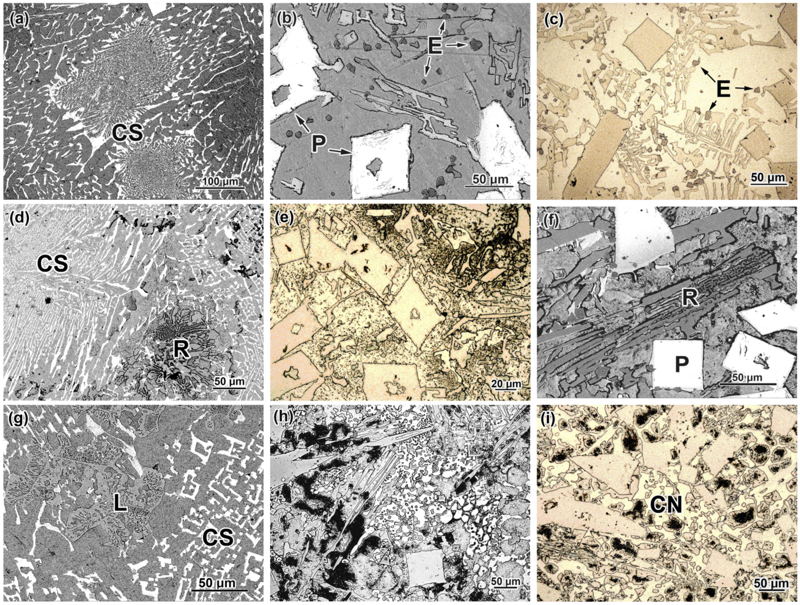
3.1. As-Cast Structure of Studied Alloys
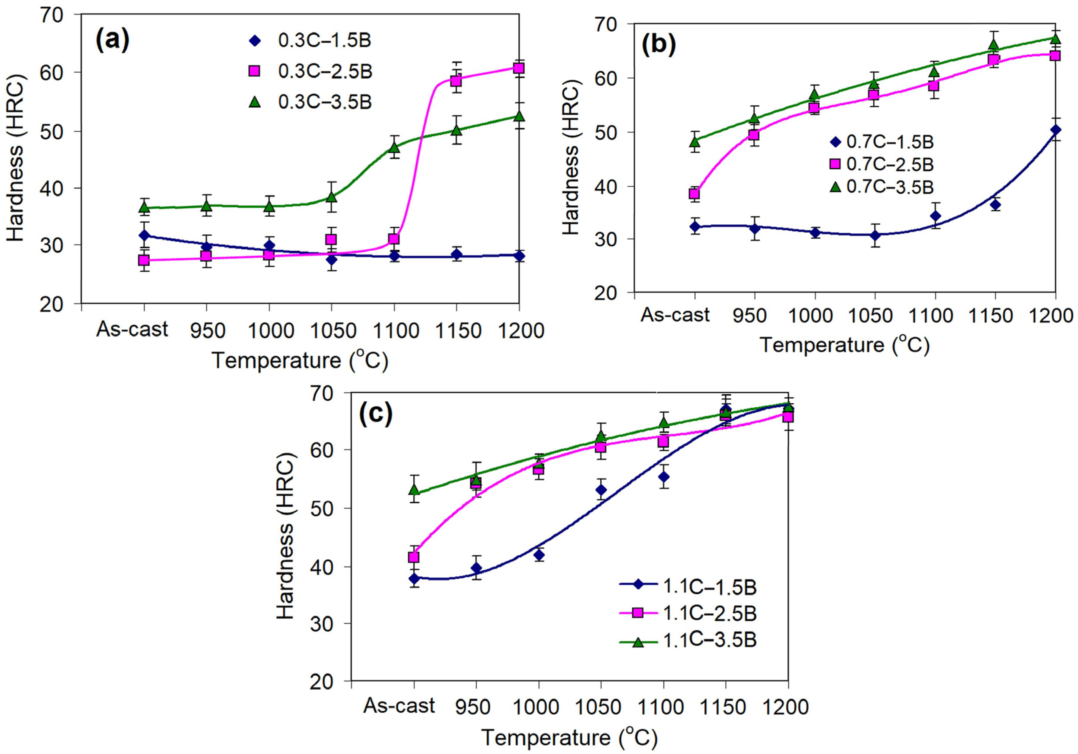
3.2. Effect of Quenching Temperature on Bulk Hardness
3.3. Effect of the Quenching Temperature on the Wear Rate
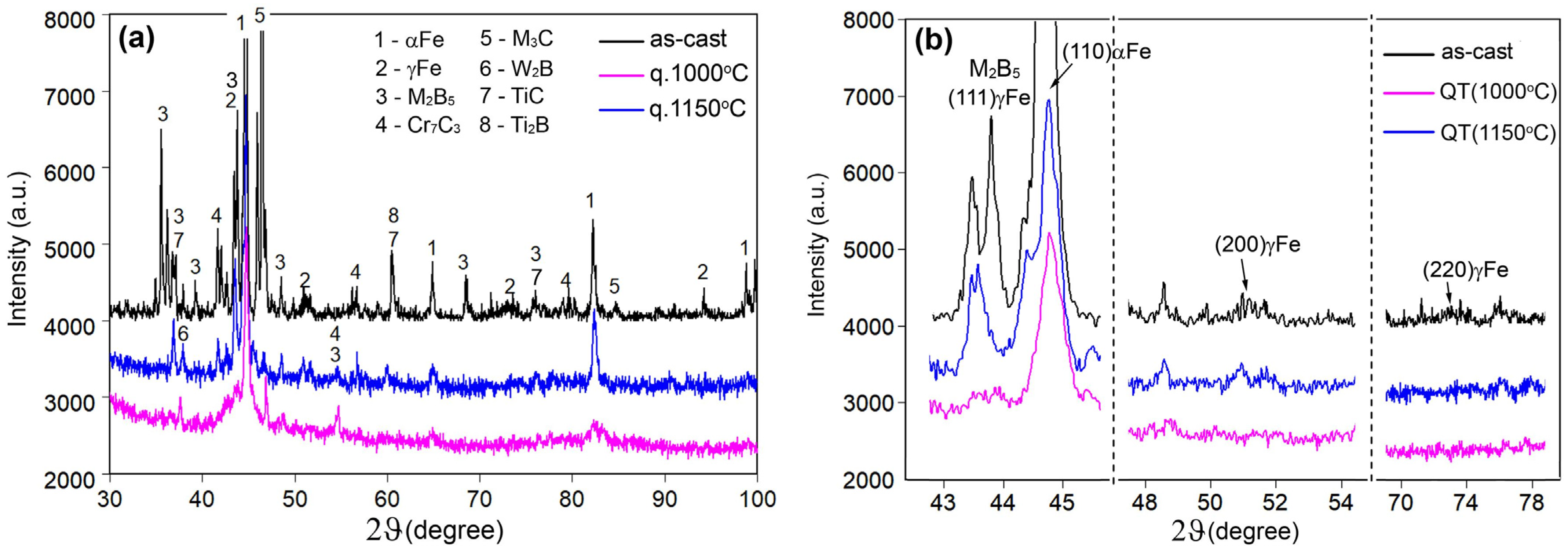
3.4. Effect of Quenching Temperature on Structure Evolution
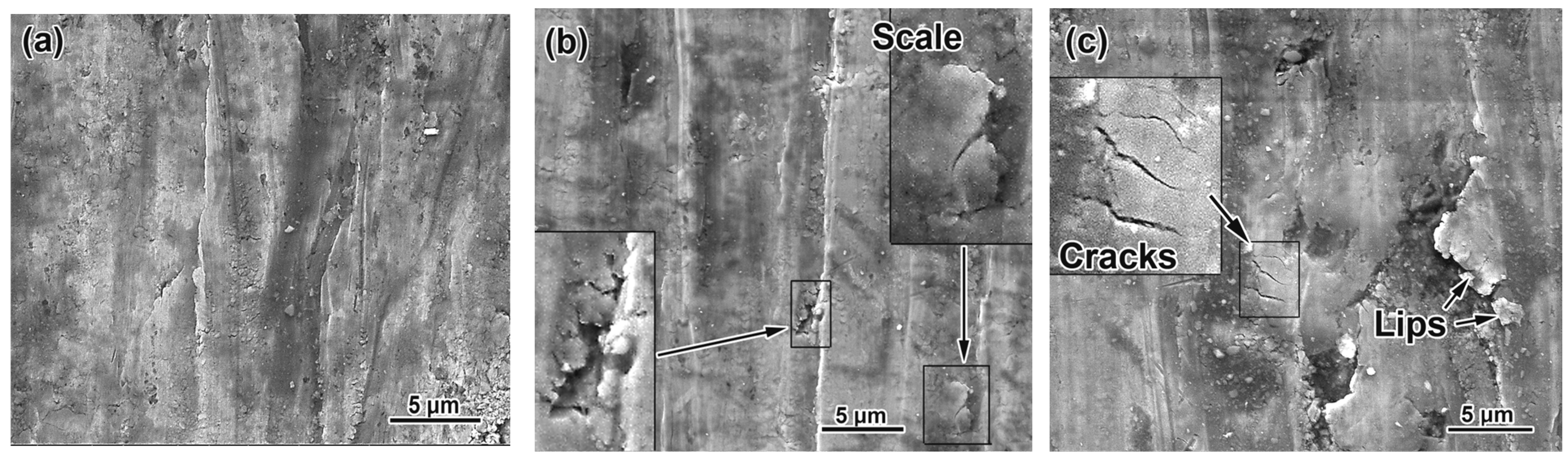
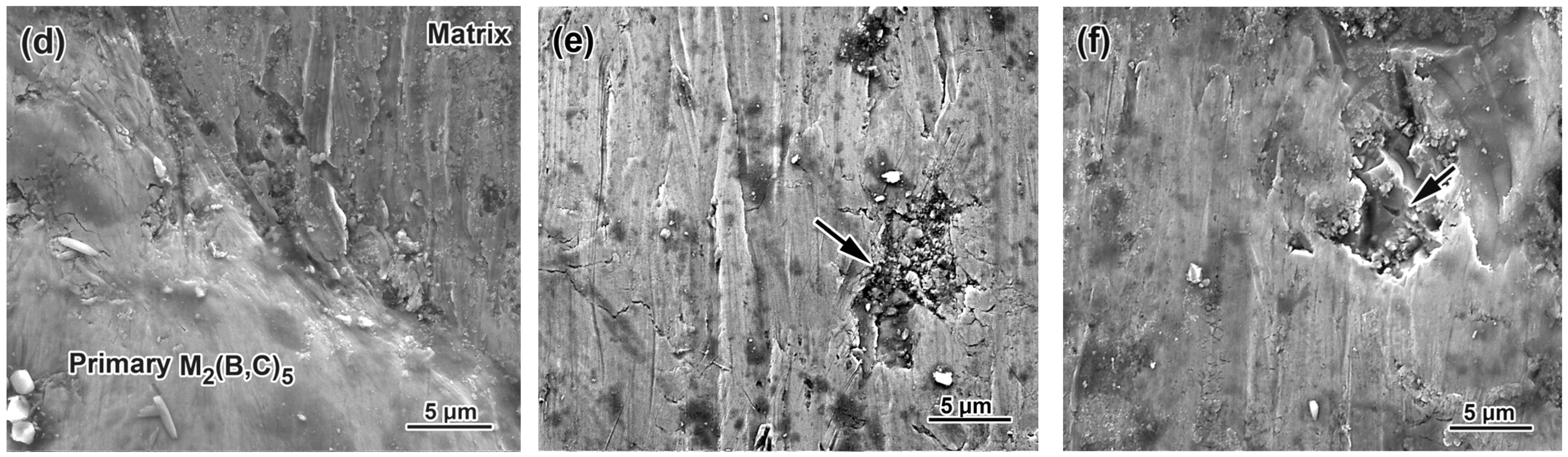
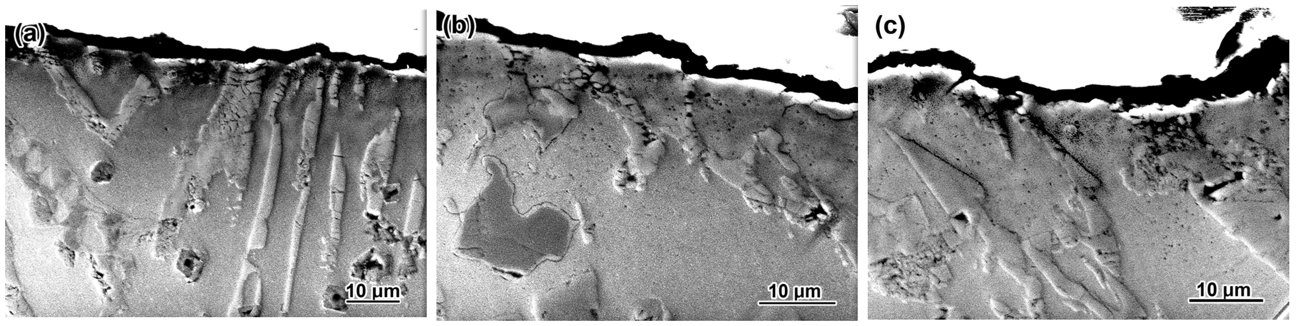
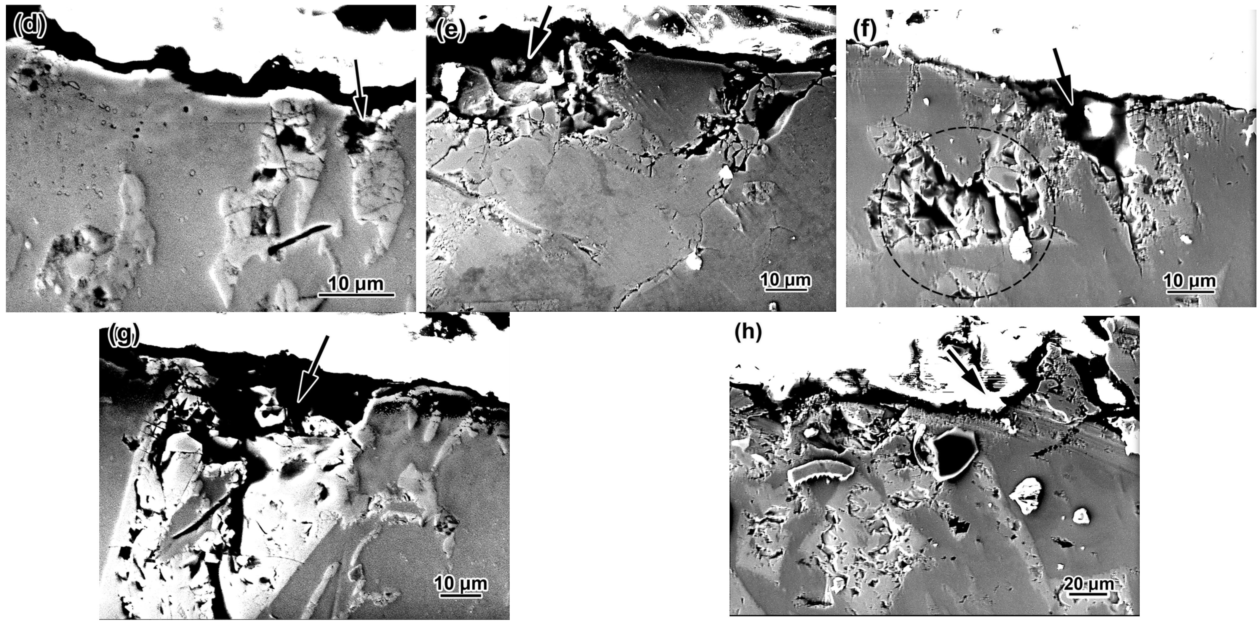
3.5. Worn Surface Characterization
4. Analysis of Results
4.1. “Quenching Temperature—Microstructure—Properties” Correlations
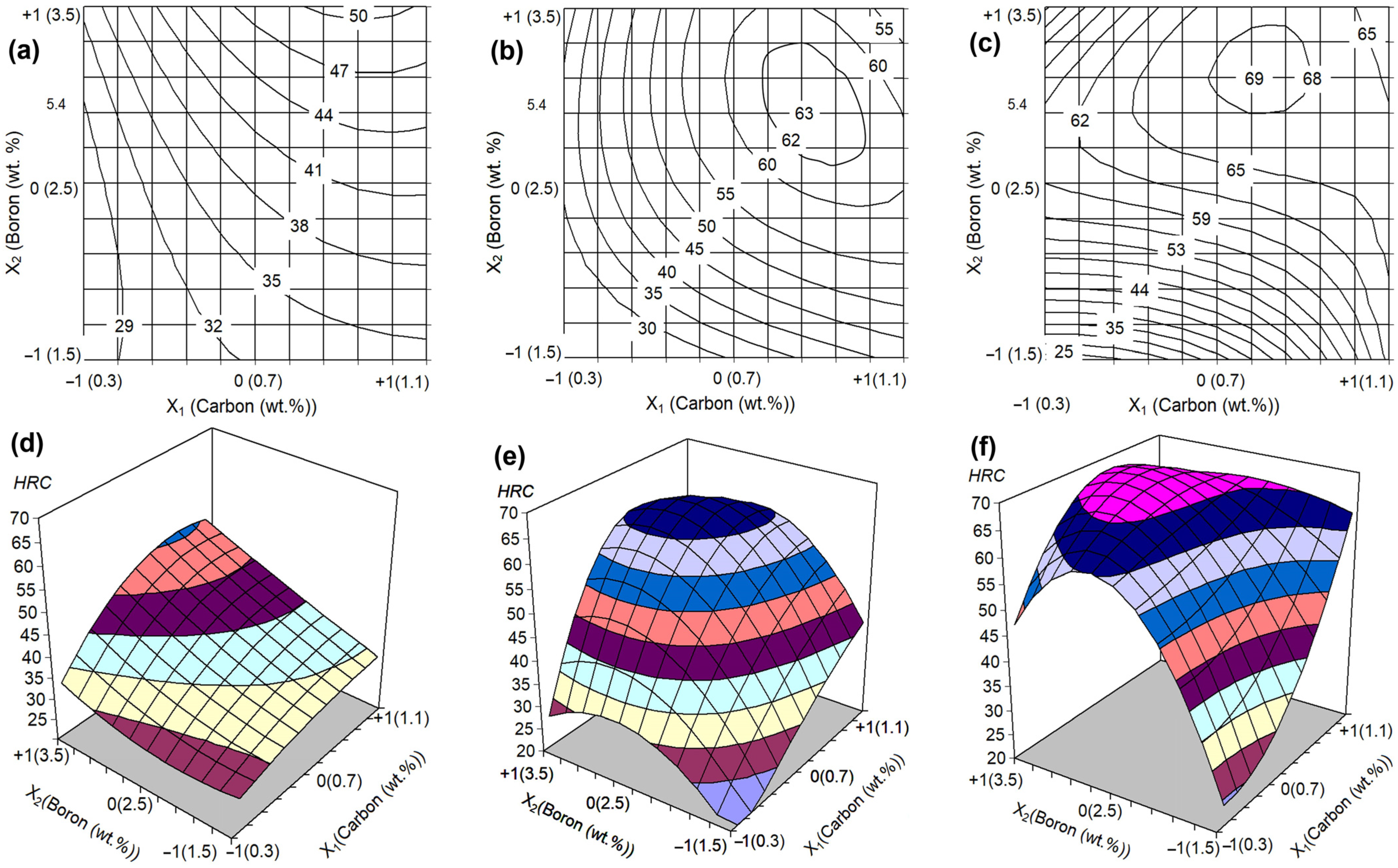
4.2. Effect of C and B Contents on Bulk Hardness and Wear Rate Depending on QT
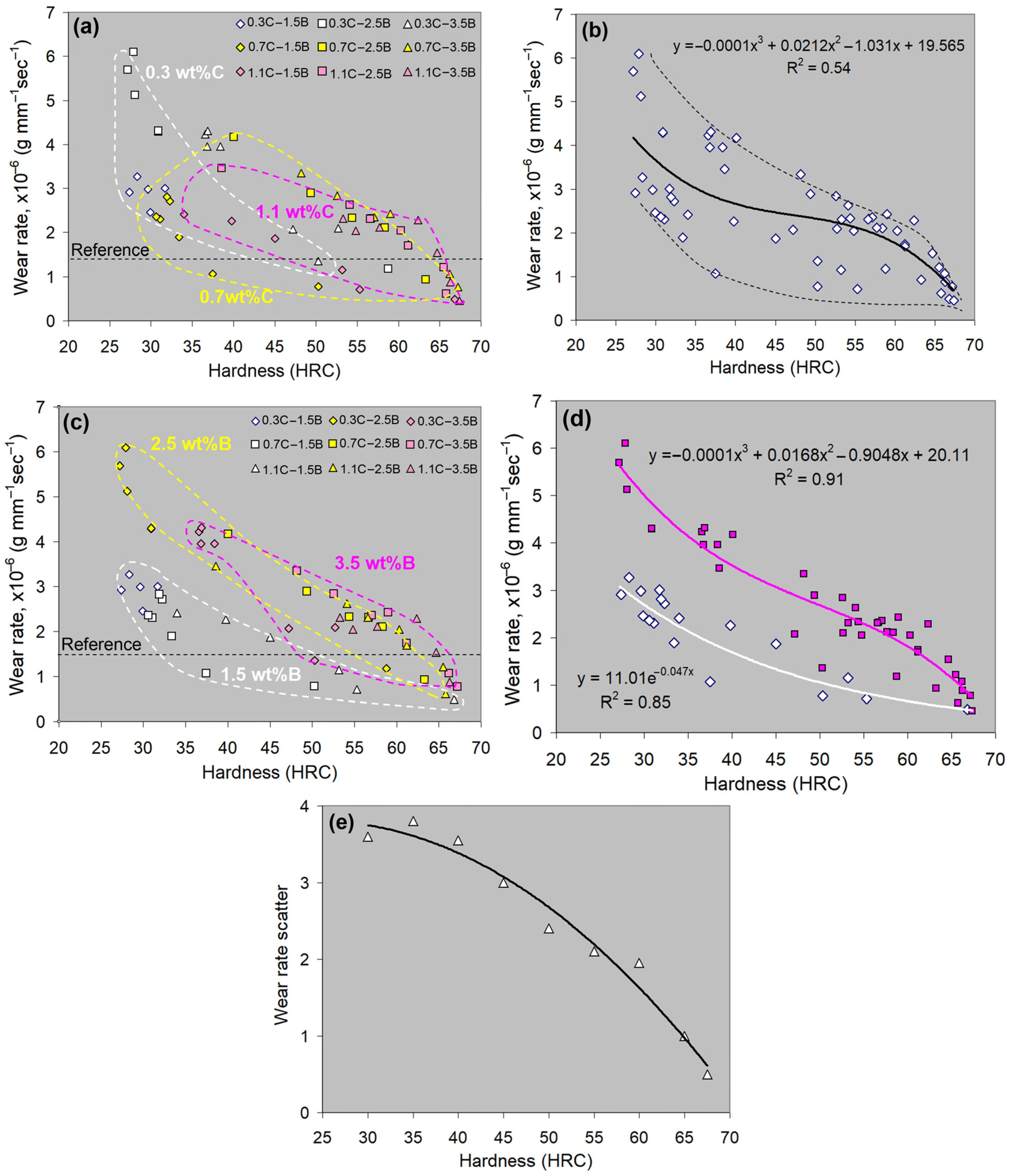
4.3. “Hardness-Wear Rate” Correlations
- -
- for 1.5 wt.% B-alloys:
- -
- for 2.5–3.5 wt.% B-alloys:
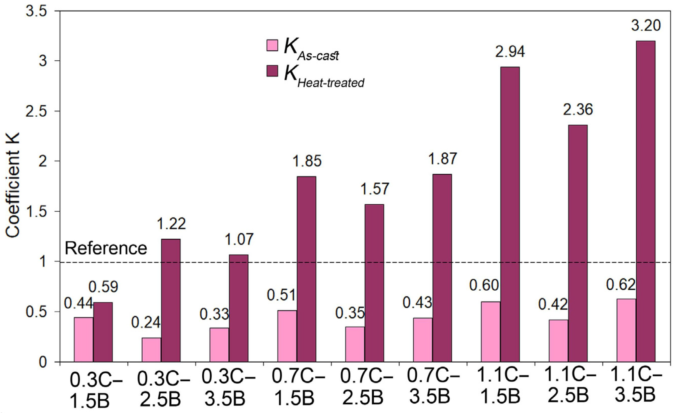
4.4. Practical Aspects of Using Hybrid MCCIs
5. Conclusions
- An increase in the QT from 950 to 1150–1200 °C improved most alloys’ hardness and wear resistance. Under low carbon (0.3 wt.%) and/or boron (1.5 wt.%) contents, a noticeable increase in hardness was observed at a QT above 1050 °C, reaching the maximum of 50–59 HRC. In other alloys, the hardness increased proportionally to the QT starting from 950 °C and reached 63–67 HRC. Accordingly, the wear rate decreased by three to six times (relative to the as-cast state). This was due to the formation of a martensitic matrix strengthened by secondary carboboride precipitates. Alloy 0.3C–1.5B retained a ferritic matrix regardless of the QT, and its properties were hardly changed by quenching.
- Carbon increased the wear resistance of MCCIs due to the formation of the carboborides M(C,B), M7(C,B)3, and M3(C,B), as well as by expanding the γ-area, thus contributing to the appearance of the martensitic matrix under the quench cooling. Boron had a versatile effect on wear resistance, which is associated, on the one hand, with the formation of wear-resistant borocarbide phases and, on the other, with the occurrence of coarse primary inclusions that were easily spalled off during wear.
- At any hardness, the alloys with a near-eutectic structure exhibited a higher wear resistance as compared to the hypereutectic ones. This is attributed to a more favorable wear mechanism of the multi-cycle formation/removal of the fine micro-scales. In hypereutectic alloys, the predominant wear mechanism is a spalling of coarse primary borocarbides. With the QT increase, the difference in the wear rate of alloys decreased due to matrix hardness improvement: the hard matrix better resisted wear, preventing the easier exposure and fracture of primary borocarbides.
- The factorial design of experiment 32 was used to optimize the alloy composition. According to the regression models derived, the highest wear resistance is attributed to the MCCI with 1.1 wt.% C and 1.5 wt.% B quenched from 1150 °C. Under the testing, the optimized alloy exhibited a hardness of 67 HRC and a wear rate of 0.88 × 10⁻⁶ g·mm−1·s−1. A similar wear resistance was shown by MCCI with 1.1 wt.% C and 3.5 wt.% B (quenching from 1200 °C, 67 HRC, WR of 0.81 × 10⁻⁶ g·mm−1·s−1). The above alloys were 2.94 and 3.20 times more wear-resistant than the reference alloy (a 13 wt.% Cr-cast iron, 66 HRC) indicating the high potential of the MCCIs to stand hard-abrasive applications.
Author Contributions
Funding
Institutional Review Board Statement
Informed Consent Statement
Data Availability Statement
Acknowledgments
Conflicts of Interest
References
- Doğan, Ö.N.; Hawk, J.A.; Laird, G. Solidification Structure and Abrasion Resistance of High Chromium White Irons. Metall. Mater. Trans. A 1997, 28, 1315–1328. [Google Scholar] [CrossRef]
- Ngqase, M.; Pan, X. An Overview on Types of White Cast Irons and High Chromium White Cast Irons. J. Phys. Conf. Ser. 2019, 1495, 012023. [Google Scholar] [CrossRef]
- Fashu, S.; Trabadelo, V. Development and Performance of High Chromium White Cast Irons (HCWCIs) for Wear–Corrosive Environments: A Critical Review. Metals 2023, 13, 1831. [Google Scholar] [CrossRef]
- Chabak, Y.; Efremenko, V.; Zurnadzhy, V.; Puchý, V.; Petryshynets, I.; Efremenko, B.; Fedun, V.; Shimizu, K.; Bogomol, I.; Kulyk, V.; et al. Structural and Tribological Studies of “(TiC+WC)/Hardened Steel” PMMC Coating Deposited by Air Pulsed Plasma. Metals 2022, 12, 218. [Google Scholar] [CrossRef]
- Matsubara, Y. Research and Development of Abrasion Wear Resistant Cast Alloys for Rolls of Rolling and Pulverizing Mills; Kurume National College of Technology: Kurume, Japan, 2002; p. 30. [Google Scholar]
- A600-92a; Standard Specification for Tool Steel High Speed. ASTM International: West Conshohocken, PA, USA, 2016.
- Pasini, W.M.; Belle, M.R.; Pereira, L.; do Amaral, R.F.; de Barcellos, V.K. Analysis of Carbides in Multi-component Cast Iron Design Based on High Entropy Alloys Concepts. Mater. Res. 2021, 24, e20200398. [Google Scholar] [CrossRef]
- Matsubara, Y.; Sasaguri, N.; Shimizu, K. Solidification and Abrasion Wear of White Cast Irons Alloyed with 20% Carbide Forming Elements. Wear 2001, 250, 502. [Google Scholar] [CrossRef]
- Wu, H.Q.; Hashimoto, M.; Sasaguri, N.; Matsubara, Y. Solidification Sequence of Multi-Component White Cast Iron. Jpn. Foundry Eng. Soc. 1996, 68, 637–643. [Google Scholar]
- Wu, H.; Sasaguri, N.; Hashimoto, M.; Matsubara, Y. Practical Phase Diagram of Multi-Component White Cast Iron. Jpn. Foundry Eng. Soc. 1997, 69, 917–923. [Google Scholar] [CrossRef]
- Hashimoto, M.; Kubo, O.; Matsubara, Y. Analysis of Carbides in Multi-component White Cast Iron for Hot Rolling Mill Rolls. ISIJ Int. 2004, 44, 372–380. [Google Scholar] [CrossRef]
- Yu, K.; Matsubara, Y. Abrasion Wear Resistance of Alloyed White Cast Iron with Several Types of Carbides and Matrices. AFS Trans. 1998, 27, 53–58. [Google Scholar]
- Inthidech, S.; Opapaibon, J.; Yamamoto, K.; Matsubara, Y. Three Body-Type Abrasive Wear Behavior of Multi-Alloyed White Cast Iron with Different Carbon Contents Used for Hot Work Rolls. ISIJ Int. 2021, 11, 2832–2843. [Google Scholar] [CrossRef]
- Yen, C.L.; Fu, J.C.; Pan, Y.N. Research on the Wear Resistance of High-Chromium White Cast Iron and Multi-Component White Cast Iron. Adv. Mater. Res. 2013, 859, 64–69. [Google Scholar] [CrossRef]
- Ziadi, A.; Belzunce, F.J.; Rodriguez, C. The effects of heat treatment on the mechanical properties of multicomponent white cast irons. J. Mater. Sci. 2007, 42, 7579–7585. [Google Scholar] [CrossRef]
- Efremenko, V.G.; Shimizu, K.; Cheiliakh, A.P.; Pastukhova, T.V.; Chabak, Y.G.; Kusumoto, K. Abrasive Resistance of Metastable V-Cr-Mn-Ni Spheroidal Carbide Cast Irons Using the Factorial Design Method. Int. J. Miner. Metall. Mater. 2016, 23, 645–657. [Google Scholar] [CrossRef]
- Ziadi, A.; Belzunce, F.J.; Rodriguez, C.; Riba, J. Wear and oxidation behaviour of multicomponent white cast irons. Mater. Sci. Technol. 2005, 21, 1181–1186. [Google Scholar] [CrossRef]
- Zhang, Y.; Shimizu, K.; Yaer, X.; Kusumoto, K.; Efremenko, V.G. Erosive Wear Performance of Heat Treated Multi-component Cast Iron Containing Cr, V, Mn and Ni Eroded by Alumina Spheres at Elevated Temperatures. Wear 2017, 390–391, 135–145. [Google Scholar] [CrossRef]
- Bedolla-Jacuinde, A.; Guerra, F.V.; Mejia, I.; Zuno-Silva, J.; Rainforth, M. Abrasive Wear of V-Nb-Ti Alloyed High Chromium White Irons. Wear 2015, 332–333, 1006–1011. [Google Scholar] [CrossRef]
- Villanueva Bravo, S.; Kaoru, Y.; Miyahara, H.; Ogi, K. Influence of Nb, V and Ta on the Microstructure of Ni-hard type Cast Iron for Hot Steel Strip Mills. J. Metall. Eng. 2017, 2, 1–11. [Google Scholar]
- Duriagina, Z.A.; Romanyshyn, M.R.; Kulyk, V.V.; Kovbasiuk, T.M.; Trostianchyn, A.M.; Lemishka, I.A. The Character of the Structure Formation of Model Alloys of the Fe-Cr-(Zr, Zr-B) System Synthesized by Powder Metallurgy. J. Achiev. Mater. Manuf. Eng. 2020, 100, 49–57. [Google Scholar] [CrossRef]
- González-Pociño, A.; Asensio-Lozano, J.; Álvarez-Antolín, F.; García-Diez, A. Evaluation of Hardness, Sliding Wear and Strength of a Hypoeutectic White Iron with 25% Cr after Heat Treatments. Metals 2021, 11, 947. [Google Scholar] [CrossRef]
- Xiong, L.; Liu, Y.; Zeng, Q.; Lai, J.; Qiao, X. Effect of Destability Time on Microstructure and Properties of Hypoeutectic High Chromium Cast Iron. RSC Adv. 2024, 11, 7459–7467. [Google Scholar] [CrossRef] [PubMed]
- Karantzalis, A.E.; Lekatou, A.; Diavati, E. Effect of Destabilization Heat Treatments on the Microstructure of High-Chromium Cast Iron: A Microscopy Examination Approach. J. Mater. Eng. Perform. 2009, 18, 1078–1085. [Google Scholar] [CrossRef]
- Nayak, U.P.; Mücklich, F.; Guitar, M.A. Time-Dependant Microstructural Evolution and Tribological Behaviour of a 26 wt% Cr White Cast Iron Subjected to a Destabilization Heat Treatment. Met. Mater. Int. 2023, 29, 934–947. [Google Scholar] [CrossRef]
- Bedolla-Jacuinde, A.; Arias, L.; Hernández, B. Kinetics of Secondary Carbides Precipitation in a High-Chromium White Iron. J. Mater. Eng. Perform. 2003, 12, 371–382. [Google Scholar] [CrossRef]
- Le Nué, C.; Corujeira Gallo, S.; Vahid, A.; Wang, J.; Taherishargh, M.; Attar, H.; Fabijanic, D.; Barnett, M. Destabilization Treatment and Its Influence on Microstructure and Matrix Hardness of High-Cr Cast Iron. Metall. Mater. Trans. A 2023, 54, 4952–4965. [Google Scholar] [CrossRef]
- Guitar, M.A.; Suárez, S.; Prat, O.; Duarte Guigou, M.; Gari, V.; Pereira, G.; Mücklich, F. High Chromium Cast Irons: Destabilized-Subcritical Secondary Carbide Precipitation and its Effect on Hardness and Wear Properties. J. Mater. Eng. Perform. 2018, 27, 3877–3885. [Google Scholar] [CrossRef]
- Opapaiboon, J.; Inthidech, S.; Yamamoto, K.; Matsubara, Y. Effect of V Content on Microstructure and Heat Treatment Behavior of Multi-component White Cast Iron used for Hot Work Roll Applications. Int. J. Metalcast. 2023, 18, 2484–2498. [Google Scholar] [CrossRef]
- Yokomizo, Y.; Yamamoto, K.; Sasaguri, N.; Matsubara, Y. Effect of Chromium and Vanadium Contents on Continuous Cooling Transformation Behavior of Multi-Component White Cast Iron. Key Eng. Mater. 2010, 457, 237–242. [Google Scholar] [CrossRef]
- Barutçuoğlu, B.; Koç, F.G.; Erişir, E.; Gülben, K. The Effect of Tempering Temperature on Microstructure and Wear Behavior of Tungsten and Boron Alloyed Ni-Hard 4 White Cast Irons. Int. J. Metalcast. 2024. [Google Scholar] [CrossRef]
- Opapaiboon, J.; Ayudhaya, M.S.N.; Sricharoenchai, P.; Inthidech, S.; Matsubara, Y. Effect of Chromium Content on Heat Treatment Behavior of Multi-Alloyed White Cast Iron for Abrasive Wear Resistance. Mater. Trans. 2019, 60, 346–354. [Google Scholar] [CrossRef]
- Opapaiboon, J.; Sricharoenchai, P.; Inthidech, S.; Matsubara, Y. Effect of Carbon Content on Heat Treatment Behavior of Multi-Alloyed White Cast Iron for Abrasive Wear Resistance. Mater. Trans. 2015, 56, 720–725. [Google Scholar] [CrossRef]
- Inthidech, S.; Matsubara, Y. Effects of Carbon Balance and Heat Treatment on Hardness and Volume Fraction of Retained Austenite of Semi-multi-alloyed White Cast Iron. Int. J. Metalcast. 2020, 14, 132–143. [Google Scholar] [CrossRef]
- Kovzel, M.A.; Babachenko, O.I.; Parusov, E.; Parusov, O.V. On Peculiarities of Influence of Chemical Composition on Formation of Structure and Properties of Alloyed Cast Irons in the As-Cast State. Metallofiz. Novejsie Tehnol. 2022, 44, 1347–1359. [Google Scholar] [CrossRef]
- Sukhova, O.V.; Polonskyy, V.A.; Ustinova, K.V. Corrosion-Electrochemical Properties of Quasicrystalline Al–Cu–Fe–(Si,B) and Al–Ni–Fe Alloys in NaCl Solution. Vopr. Khimii Khimicheskoi Tekhnologii 2019, 124, 46–52. [Google Scholar] [CrossRef]
- Efremenko, V.G.; Chabak, Y.G.; Shimizu, K.; Golinskyi, M.A.; Lekatou, A.G.; Petryshynets, I.; Efremenko, B.V.; Halfa, H.; Kusumoto, K.; Zurnadzhy, V.I. The Novel Hybrid Concept on Designing Advanced Multi-Component Cast Irons: Effect of Boron and Titanium (Thermodynamic Modelling, Microstructure and Mechanical Property Evaluation). Mater. Charact. 2023, 197, 112691. [Google Scholar] [CrossRef]
- Chabak, Y.G.; Shimizu, K.; Efremenko, V.G.; Golinskyi, M.A.; Kusumoto, K.; Zurnadzhy, V.I.; Efremenko, A.V. Microstructure and Phase Elemental Distribution in High-Boron Multi-Component Cast Irons. Int. J. Miner. Metall. Mater. 2022, 29, 78–87. [Google Scholar] [CrossRef]
- Efremenko, V.G.; Chabak, Y.G.; Lekatou, A.G.; Shimizu, K.; Petryshynets, I.; Zurnadzhy, V.I.; Efremenko, B.V.; Kusumoto, K.; Halfa, H. Microstructural Map and Phase Chemical Compositions in Hybrid Multi-component Cast Alloys Fe-W-Mo-V-Cr-Ti-(1.5–3.5 Wt Pct)B-(0.3–1.1 Wt Pct)C. Metall. Mater. Trans. A 2024, 55, 2756–2772. [Google Scholar] [CrossRef]
- Sukhova, O.V. Solubility of Cu, Ni, Mn in Boron-Rich Fe-B-C Alloys. Phys. Chem. Solid State 2021, 22, 110–116. [Google Scholar] [CrossRef]
- Lozynskyi, V.; Trembach, B.; Hossain, M.M.; Kabir, M.H.; Silchenko, Y.; Krbata, M.; Sadovyi, K.; Kolomiitse, O.; Ropyak, L. Prediction of Phase Composition and Mechanical properties Fe-Cr-C-B-Ti-Cu hardfacing alloys: Modeling and experimental Validations. Heliyon 2024, 10, e25199. [Google Scholar] [CrossRef]
- Yen, C.L.; Kun, L.L.; Pan, Y.N. Simulation of the Phase Diagrams for High-Chromium White Cast Irons and Multi-Component White Cast Irons. Adv. Mater. Res. 2013, 848, 39–45. [Google Scholar] [CrossRef]
- Ren, X.; Han, L.; Fu, H.; Wang, J. Research on Properties of Borocarbide in High Boron Multi-Component Alloy with Different Mo Concentrations. Materials 2021, 14, 3709. [Google Scholar] [CrossRef]
- Lentz, J.; Röttger, A.; Theisen, W. Hardness and modulus of Fe2B, Fe3(C,B), and Fe23(C,B)6 borides and carboborides in the Fe-C-B system. Mater. Charact. 2018, 135, 192–202. [Google Scholar] [CrossRef]
- Ma, S.; Zhang, J. Wear resistant high boron cast alloy—A review. Rev. Adv. Mater. Sci. 2016, 44, 54. [Google Scholar]
- Liu, Z.L.; Xiang, C.; Li, Y.X.; Hu, K.H. High Boron Iron-Based Alloy and Its Modification. J. Iron Steel Res. Int. 2009, 16, 37–54. [Google Scholar] [CrossRef]
- Chabak, Y.; Petryshynets, I.; Efremenko, V.; Golinskyi, M.; Shimizu, K.; Zurnadzhy, V.; Sili, I.; Halfa, H.; Efremenko, B.; Puchy, V. Investigations of Abrasive Wear Behaviour of Hybrid High-Boron Multi-Component Alloys: Effect of Boron and Carbon Contents by the Factorial Design Method. Materials 2023, 16, 2530. [Google Scholar] [CrossRef]
- Chen, X.; Li, Y. Effect of heat treatment on microstructure and mechanical properties of high boron white cast iron. Mater. Sci. Eng. A 2010, 528, 770–775. [Google Scholar] [CrossRef]
- Ma, S.; Xing, J.; Liu, G.; Yi, D.; Fu, H.; Zhang, J.; Li, Y. Effect of chromium concentration on microstructure and properties of Fe-3.5B alloy. Mater. Sci. Eng. A 2010, 527, 6800–6808. [Google Scholar] [CrossRef]
- Lentz, J.; Röttger, A.; Theisen, W. Microstructures, Heat Treatment, and Properties of Boron-Alloyed Tool Steels. Steel Res. Int. 2019, 91, 1900416. [Google Scholar] [CrossRef]
- Jiju, A. Design of Experiments for Engineers and Scientists; Elsevier: Amsterdam, The Netherlands, 2014. [Google Scholar]
- Novik, F.S.; Arsov, J.B. Optimization of Metal Technology Processes by Methods of Planning Experiments; Mashinostroenie: Moscow, Russia, 1980. [Google Scholar]
- Gonzalez-Pociño, A.; Alvarez-Antolin, F.; Asensio-Lozano, J. Influence of Thermal Parameters Related to Destabilization Treatments on Erosive Wear Resistance and Microstructural Variation of White Cast Iron Containing 18% Cr. Application of Design of Experiments and Rietveld Structural Analysis. Materials 2019, 19, 3252. [Google Scholar] [CrossRef] [PubMed]
- Hohne, G.W.H.; Hemminger, W.; Flammersheim, H.-J. Differential Scanning Calorimetry: An Introduction for Practitioners; Springer: Berlin/Heidelberg, Germany, 1996. [Google Scholar]
- Khaled, I.; Nofal, A.A. Effect of Titanium Addition on Structure and Properties of the As-Cast High Cr-Mo White Iron. J. Mater. Res. 2012, 103, 362–370. [Google Scholar] [CrossRef]
- Gutnyk, M.; Nürnberger, F. The Fe-C diagram—History of its evolution. Hist. Sci. Technol. 2023, 13, 243–262. [Google Scholar] [CrossRef]
- Greer, A.L. The Use of DSC to Determine the Curie Temperature of Metallic Glasses. Thermochim. Acta 1980, 42, 193–222. [Google Scholar] [CrossRef]
- Leu, M.S.; Tsai, C.S.; Lin, C.S.; Lin, S.T. The Determination of Curie Temperature by Differential Scanning Calorimetry under Magnetic Field. IEEE Trans. Magn. 1991, 27, 5414–5416. [Google Scholar] [CrossRef]
- Loi Brião, S.; Andrade, J.R.; Lobato, F.; dos Santos Paes, L.E.; Vilarinho, L.; Reis, R. An In-House Finite Volume Analysis to Predict the Heat Affected Zone in TIG Welding. In Proceedings of the 18th Brazilian Congress of Thermal Sciences and Engineering (ABCM 2020), Bento Gonçalves, Brazil, 16–20 November 2020; pp. 1–8. [Google Scholar] [CrossRef]
- Kohne, T.; Fahlkrans, J.; Stormvinter, A.; Maawad, E.; Winkelmann, A.; Hedström, P.; Borgenstam, A. Evolution of Martensite Tetragonality in High-Carbon Steels Revealed by In Situ High-Energy X-Ray Diffraction. Metall Mater Trans A 2023, 54, 1083–1100. [Google Scholar] [CrossRef]
- Efremenko, B.V.; Shimizu, K.; Espallargas, N.; Efremenko, V.G.; Kusumoto, K.; Chabak, Y.G.; Belik, A.G.; Chigarev, V.V.; Zurnadzhy, V.I. High-Temperature Solid Particle Erosion of Cr-Ni-Fe-C Arc Cladded Coatings. Wear 2020, 460–461, 203439. [Google Scholar] [CrossRef]
- Hashmi, A.W.; Mali, H.S.; Meena, A.; Saxena, K.K.; Puerta, A.P.V.; Prakash, C.; Buddhi, D.; Davim, J.P.; Abdul-Zahra, D.S. Understanding the Mechanism of Abrasive-Based Finishing Processes Using Mathematical Modeling and Numerical Simulation. Metals 2022, 12, 1328. [Google Scholar] [CrossRef]
- Lesyk, D.A.; Mordyuk, B.N.; Dzhemelinskyi, V.V.; Voloshko, S.M.; Burmak, A.P. Optimization of Ultrasonic Impact Treatment for Surface Finishing and Hardening of AISI O2 Tool Steel by Experimental Design. J. Mater. Eng. Perform. 2022, 31, 8567–8584. [Google Scholar] [CrossRef]
- Chabak, Y.; Efremenko, B.; Petryshynets, I.; Efremenko, V.; Lekatou, A.G.; Zurnadzhy, V.; Bogomol, I.; Fedun, V.; Kovaľ, K.; Pastukhova, T. Structural and Tribological Assessment of Biomedical 316 Stainless Steel Subjected to Pulsed-Plasma Surface Modification: Comparison of LPBF 3D Printing and Conventional Fabrication. Materials 2021, 14, 7671. [Google Scholar] [CrossRef]
- Okamoto, H.; Schlesinger, M.E.; Mueller, E.M. ASM Handbook Volume 3: Alloy Phase Diagrams; ASM International: Almere, The Netherlands, 2016; ISBN 978-1-62708-070-5. [Google Scholar]
- Žmak, I.; Ćorić, D.; Mandić, V.; Ćurković, L. Hardness and Indentation Fracture Toughness of Slip Cast Alumina and Alumina-Zirconia Ceramics. Materials 2020, 13, 122. [Google Scholar] [CrossRef]
- Wefers, K.; Misra, C. Oxides and Hydroxides of Aluminum; Alcoa Research Laboratories: New Kensington, PA, USA, 1987. [Google Scholar]
- Pierson, H.O. Handbook of Refractory Carbides and Nitrides. Properties, Characteristics, Processing and Applications; Noyes Publications: Westwood, CA, USA, 1996. [Google Scholar]
- Kulik, E.; Nishiyama, N.; Higo, Y.; Gaida, N.A.; Katsura, T. Hardness of Polycrystalline SiO2 Coesite. J. Am. Ceram. Soc. 2019, 102, 2251–2256. [Google Scholar] [CrossRef]
- Koval’, A.D.; Efremenko, V.G.; Brykov, M.N.; Andrushchenko, M.I.; Kulikovskii, R.A.; Efremenko, A.V. Principles for developing grinding media with increased wear resistance. Part 2. Optimization of Steel Composition to Suit Conditions of Operation of Grinding Media. J. Frict. Wear 2012, 33, 153–159. [Google Scholar] [CrossRef]
- Malinov, L.S.; Malinov, V.L.; Burova, D.V. Impact of Metastable Austenite on the Wear Resistance of Tool Steel. J. Frict. Wear 2018, 39, 349–353. [Google Scholar] [CrossRef]


| Alloy Designation | Coded Levels of the Variables | Content (wt.%) | ||||||||||
|---|---|---|---|---|---|---|---|---|---|---|---|---|
| X1 (C) | X2 (B) | C | B | Si | Mn | W | Mo | V | Cr | Ti | Al | |
| 0.3C–1.5B | –1 | –1 | 0.22 | 1.68 | 0.95 | 1.06 | 5.57 | 4.80 | 5.21 | 10.39 | 2.55 | 0.15 |
| 0.3C–2.5B | –1 | 0 | 0.25 | 2.70 | 1.05 | 1.21 | 4.68 | 5.14 | 5.01 | 9.85 | 2.83 | 0.05 |
| 0.3C–3.5B | –1 | 1 | 0.30 | 3.62 | 1.14 | 0.88 | 5.35 | 5.19 | 5.35 | 10.32 | 2.78 | 0.08 |
| 0.7C–1.5B | 0 | –1 | 0.77 | 1.62 | 1.12 | 1.16 | 5.84 | 5.38 | 4.97 | 10.45 | 2.93 | 0.05 |
| 0.7C–2.5B | 0 | 0 | 0.72 | 2.75 | 1.10 | 0.90 | 5.05 | 5.57 | 5.78 | 10.35 | 2.60 | 0.04 |
| 0.7C–3.5B | 0 | 1 | 0.70 | 3.61 | 1.18 | 1.07 | 4.67 | 4.63 | 5.40 | 10.21 | 2.71 | 0.08 |
| 1.1C–1.5B | 1 | –1 | 1.20 | 1.59 | 1.07 | 1.10 | 5.42 | 4.48 | 5.37 | 10.41 | 2.38 | 0.10 |
| 1.1C–2.5B | 1 | 0 | 1.11 | 2.73 | 1.10 | 1.07 | 4.85 | 4.69 | 5.26 | 10.36 | 2.43 | 0.14 |
| 1.1C–3.5B | 1 | 1 | 1.13 | 3.57 | 1.06 | 1.03 | 4.50 | 4.08 | 4.79 | 9.94 | 2.39 | 0.11 |
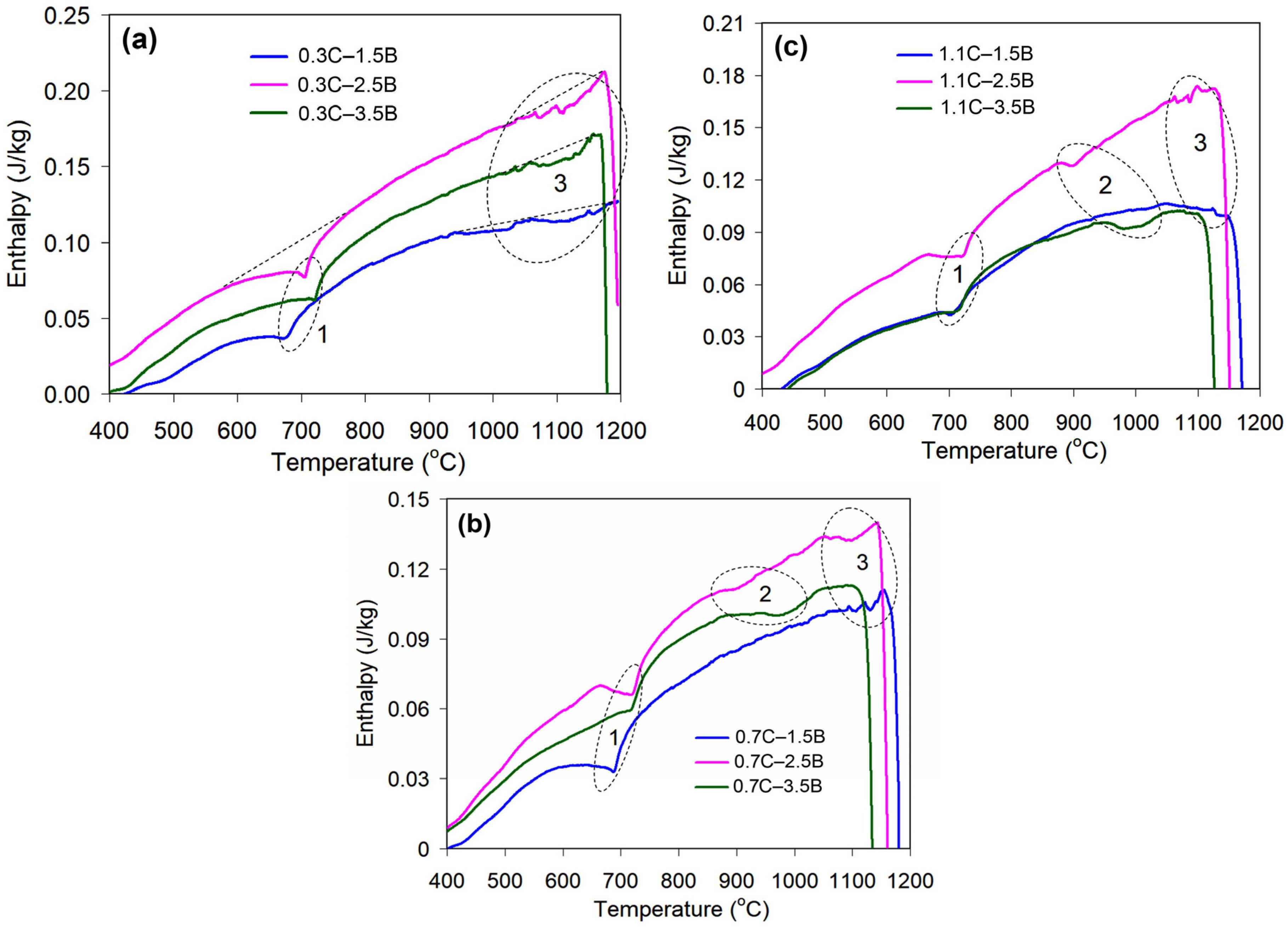
| Alloy | The Temperature Range (°C) of the Endothermic Effects | |||
|---|---|---|---|---|
| Effect #1 | Effect #2 | Effect #3 | Melting | |
| 0.3C–1.5B | 593–757 | – | 979–1200 | >1200 |
| 0.3C–2.5B | 598–776 | – | 1020–1178 | >1178 |
| 0.3C–3.5B | 581–780 | – | 1023–1170 | >1170 |
| 0.7C–1.5B | 578–747 | – | 1065–1152 | >1152 |
| 0.7C–2.5B | 662–790 | 880–974 | 1062–1146 | >1146 |
| 0.7C–3.5B | 622–761 | 894–1048 | – | >1120 |
| 1.1C–1.5B | 635–741 | – | 1060–1160 | >1160 |
| 1.1C–2.5B | 677–771 | 883–960 | 1067–1135 | >1135 |
| 1.1C–3.5B | 635–767 | 956–1052 | – | >1113 |
Disclaimer/Publisher’s Note: The statements, opinions and data contained in all publications are solely those of the individual author(s) and contributor(s) and not of MDPI and/or the editor(s). MDPI and/or the editor(s) disclaim responsibility for any injury to people or property resulting from any ideas, methods, instructions or products referred to in the content. |
© 2024 by the authors. Licensee MDPI, Basel, Switzerland. This article is an open access article distributed under the terms and conditions of the Creative Commons Attribution (CC BY) license (https://creativecommons.org/licenses/by/4.0/).
Share and Cite
Chabak, Y.; Efremenko, V.; Petryshynets, I.; Golinskyi, M.; Shimizu, K.; Efremenko, B.; Kudin, V.; Azarkhov, A. Role of Quenching Temperature Selection in the Improvement of the Abrasive (Al2O3) Wear Resistance of Hybrid Multi-Component Cast Irons. Materials 2024, 17, 3742. https://doi.org/10.3390/ma17153742
Chabak Y, Efremenko V, Petryshynets I, Golinskyi M, Shimizu K, Efremenko B, Kudin V, Azarkhov A. Role of Quenching Temperature Selection in the Improvement of the Abrasive (Al2O3) Wear Resistance of Hybrid Multi-Component Cast Irons. Materials. 2024; 17(15):3742. https://doi.org/10.3390/ma17153742
Chicago/Turabian StyleChabak, Yuliia, Vasily Efremenko, Ivan Petryshynets, Michail Golinskyi, Kazumichi Shimizu, Bohdan Efremenko, Vadim Kudin, and Alexander Azarkhov. 2024. "Role of Quenching Temperature Selection in the Improvement of the Abrasive (Al2O3) Wear Resistance of Hybrid Multi-Component Cast Irons" Materials 17, no. 15: 3742. https://doi.org/10.3390/ma17153742