
Effect of Discharge Gas Composition on SiC Etching in an HFE-347mmy/O2/Ar Plasma


Abstract
1. Introduction
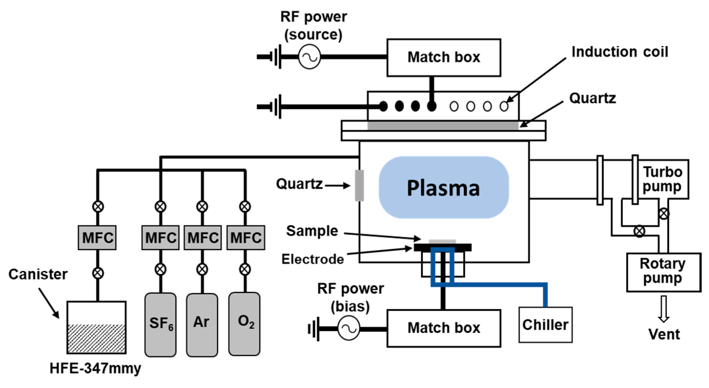
2. Materials and Methods
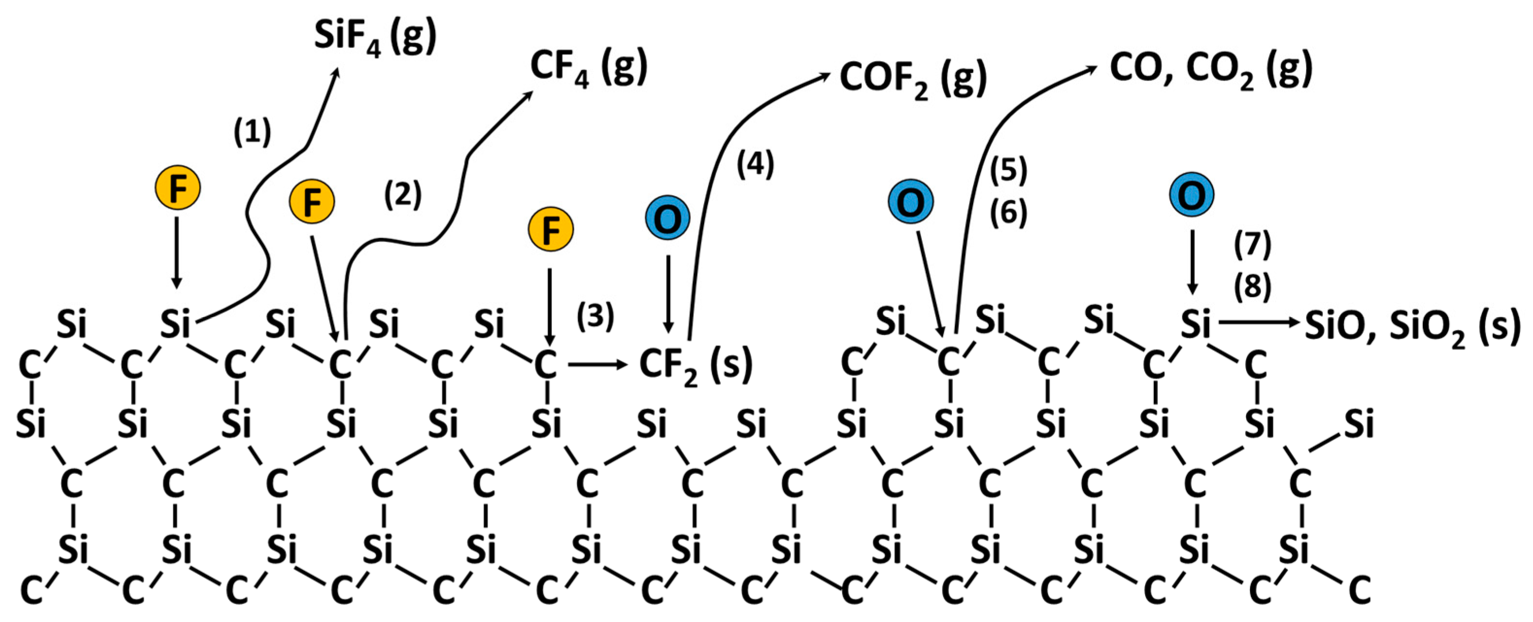
3. Surface Reaction Mechanisms in Plasma Etching of SiC
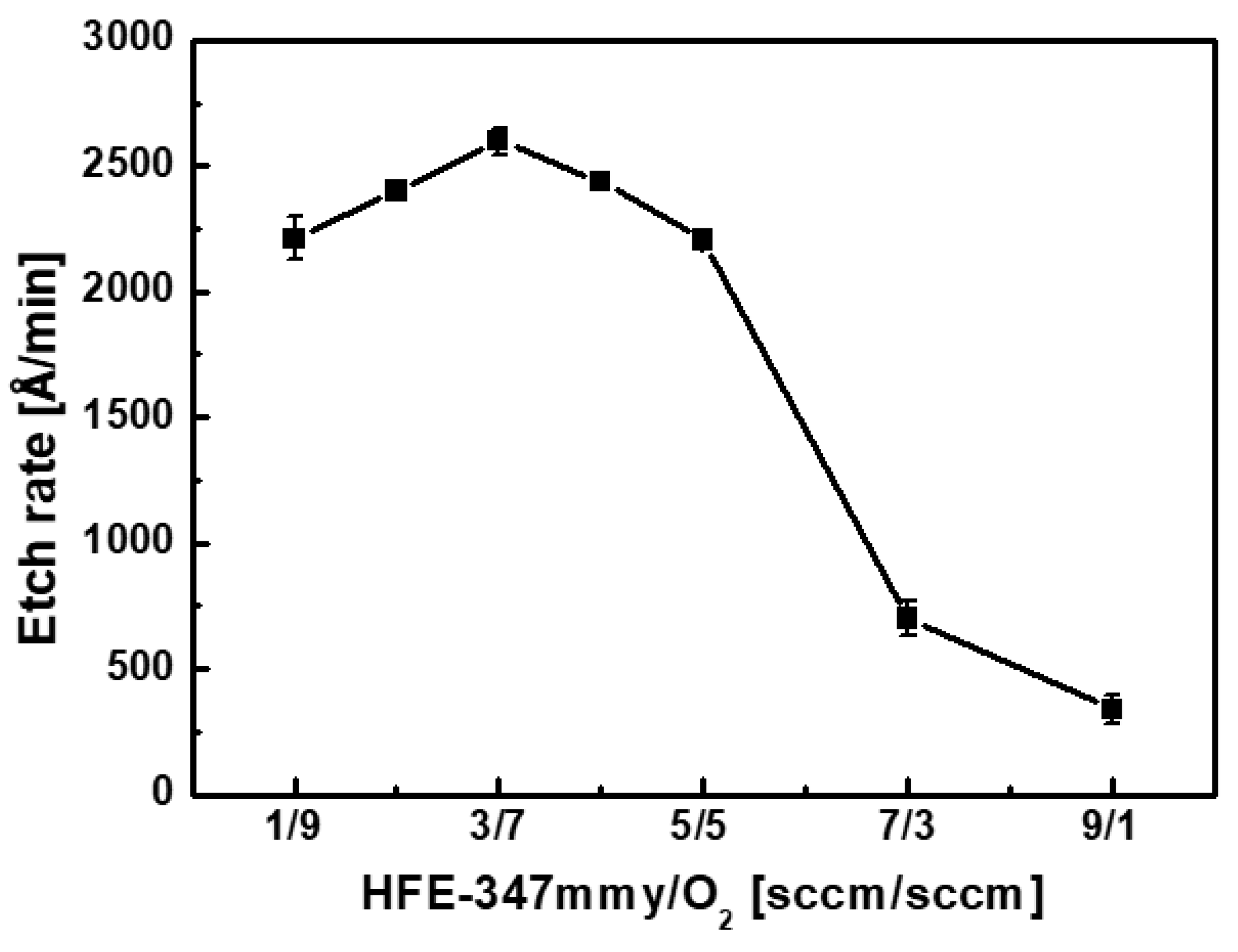
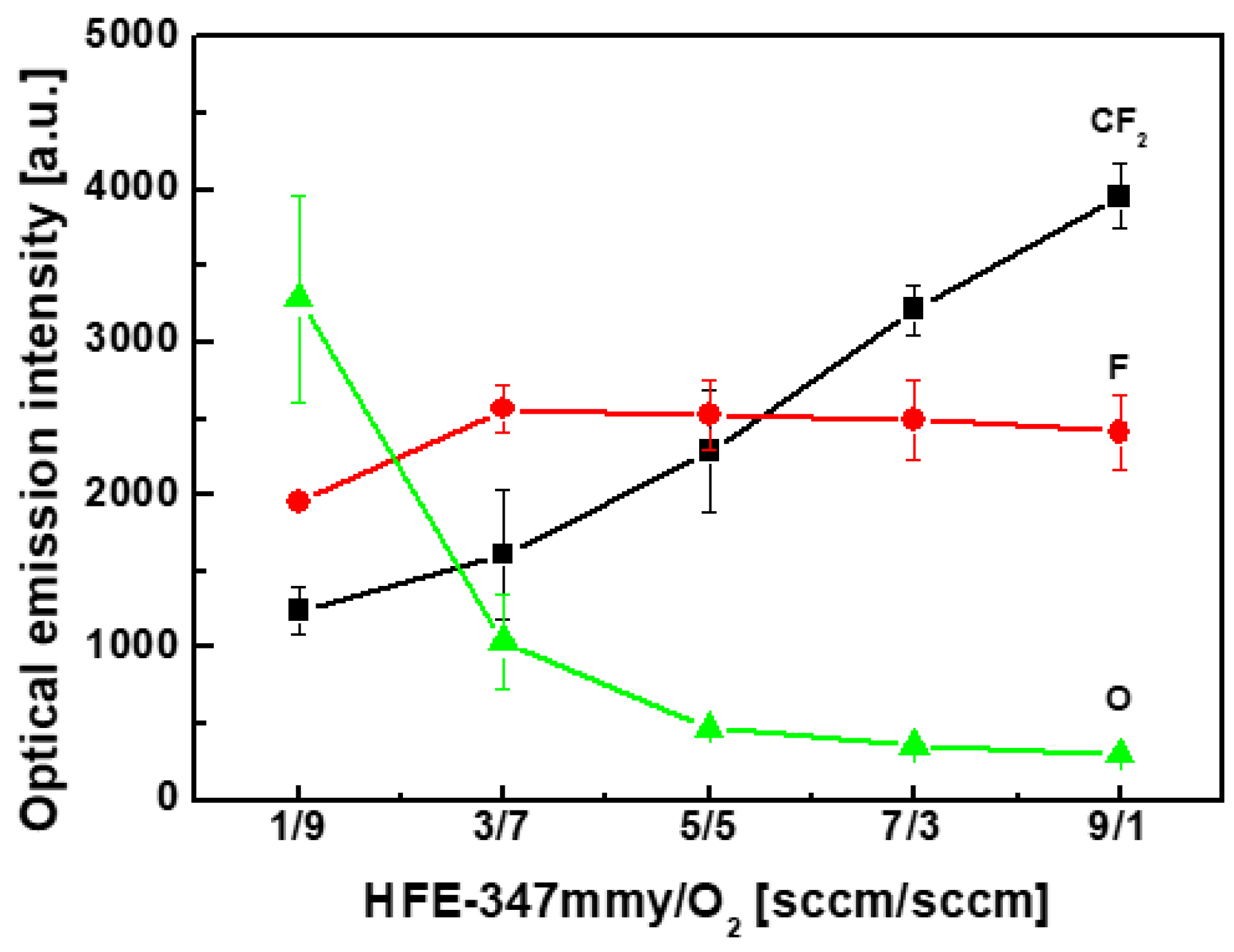
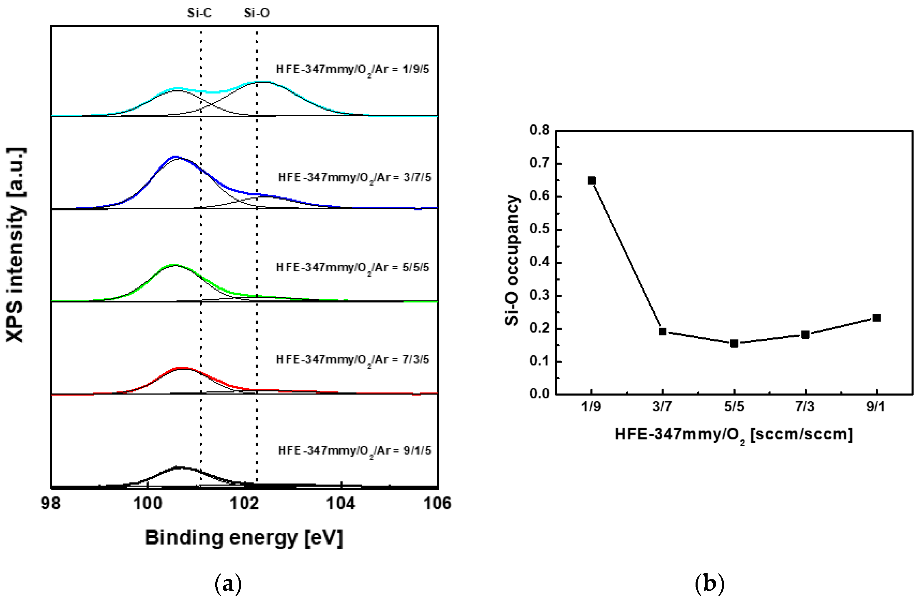
4. Results and Discussion
5. Conclusions
Author Contributions
Funding
Institutional Review Board Statement
Informed Consent Statement
Data Availability Statement
Conflicts of Interest
Nomenclature
| g | gas phase |
| s | solid phase |
References
- Pirnaci, M.D.; Spitaleri, L.; Tenaglia, D.; Perricelli, F.; Fragalà, M.E.; Bongiorno, C.; Gulino, A. Systematic characterization of plasma-etched trenches on 4H-SiC wafers. ACS Omega 2021, 6, 20667–20675. [Google Scholar] [CrossRef] [PubMed]
- Maboudian, R.; Carraro, C.; Senesky, D.G.; Roper, C.S. Advances in silicon carbide science and technology at the micro and nanoscales. J. Vac. Sci. Technol. A 2013, 31, 050805. [Google Scholar] [CrossRef]
- Dinh, T.; Phan, H.-P.; Kashaninejad, N.; Nguyen, T.-K.; Dao, D.V.; Nguyen, N.-T. An on-chip SiC MEMS device with integrated heating, sensing, and microfluidic cooling systems. Adv. Mater. Interfaces 2018, 5, 1800764. [Google Scholar] [CrossRef]
- Kumar, A.; Moradpour, M.; Losito, M.; Franke, W.-T.; Ramasamy, S.; Baccoli, R.; Gatto, G. Wide band gap devices and their application in power electronics. Energies 2022, 15, 9172. [Google Scholar] [CrossRef]
- Leitgeb, M.; Zellner, C.; Hufnagl, C.; Schneider, M.; Schwab, S.; Hutter, H.; Schmid, U. Stacked layers of different porosity in 4H SiC substrates applying a photoelectrochemical approach. J. Electrochem. Soc. 2017, 164, E337–E347. [Google Scholar] [CrossRef]
- Naderi, N.; Hashim, M.R. Effect of different current densities on optical properties of porous silicon carbide using photoelectrochemicaletching. Mater. Lett. 2012, 88, 65–67. [Google Scholar] [CrossRef]
- Lee, J.; Efremov, A.; Kwon, K.-H. On the relationships between plasma chemistry, etching kinetics and etching residues in CF4+C4F8+Ar and CF4+CH2F2+Ar plasmas with various CF4/C4F8 and CF4/CH2F2 mixing ratios. Vacuum 2018, 148, 214–223. [Google Scholar] [CrossRef]
- Xia, J.H.; Rusli; Choy, S.F.; Gopalakrishan, R.; Tin, C.C.; Yoon, S.F.; Ahn, J. CHF3–O2 reactive ion etching of 4H-SiC and the role of oxygen. Microelectron. Eng. 2006, 83, 381–386. [Google Scholar] [CrossRef]
- Jiang, L.; Cheung, R. Impact of Ar addition to inductively coupled plasma etching of SiC in SF6/O2. Microelectron. Eng. 2004, 73–74, 306–311. [Google Scholar] [CrossRef]
- Cho, H.; Lee, K.P.; Leerungnawarat, P.; Chu, S.N.G.; Ren, F.; Pearton, S.J.; Zetterling, C.-M. High density plasma via hole etching in SiC. J. Vac. Sci. Technol. A 2001, 19, 1878–1881. [Google Scholar] [CrossRef]
- Racka-Szmidt, K.; Stonio, B.; Żelazko, J.; Filipiak, N.; Sochacki, M. A review: Inductively coupled plasma reactive ion etching of silicon carbide. Materials 2022, 15, 123. [Google Scholar] [CrossRef]
- Osipov, A.A.; Iankevich, G.A.; Speshilova, A.B.; Osipov, A.A.; Endiiarova, E.V.; Berezenko, V.I.; Tyurikova, I.V.; Tyurikov, K.S.; Alexandrov, S.E. High-temperature etching of SiC in SF6/O2 inductively coupled Plasma. Sci. Rep. 2020, 10, 19977. [Google Scholar] [CrossRef] [PubMed]
- Lee, J.; Efremov, A.; Kim, K.; Kwon, K.-H. Etching characteristics of SiC, SiO2, and Si in CF4/CH2F2/N2/Ar inductively coupled plasma: Effect of CF4/CH2F2 mixing ratio. Jpn. J. Appl. Phys. 2016, 55, 106201. [Google Scholar] [CrossRef]
- Post, G.B. Recent US State and federal drinking water guidelines for per- and polyfluoroalkyl substances. Environ. Toxicol. Chem. 2020, 40, 550–563. [Google Scholar] [CrossRef]
- Brunn, H.; Arnold, G.; Körner, W.; Rippen, G.; Steinhäuser, K.G.; Valentin, I. PFAS: Forever chemicals—Persistent, bioaccumulative and mobile. Reviewing the status and the need for their phase out and remediation of contaminated sites. Environ. Sci. Eur. 2023, 35, 20. [Google Scholar] [CrossRef]
- Cho, B.-O.; Hwang, S.-W.; Lee, G.-R.; Moon, S.H. Angular dependence of SiO2 etching in a fluorocarbon plasma. J. Vac. Sci. Technol. A 2000, 18, 2791–2798. [Google Scholar] [CrossRef]
- Lee, G.-R.; Hwang, S.-W.; Min, J.-H.; Moon, S.H. Angular dependence of SiO2 etch rate at various bias voltages in a high density CHF3 plasma. J. Vac. Sci. Technol. A 2002, 20, 1808–1814. [Google Scholar] [CrossRef]
- Lee, S.; Oh, J.; Lee, K.; Sohn, H. Ultrahigh selective etching of Si3N4 films over SiO2 films for silicon nitride gate spacer etching. J. Vac. Sci. Technol. B 2010, 28, 131–137. [Google Scholar] [CrossRef]
- Lee, J.-K.; Lee, G.-R.; Min, J.-H.; Moon, S.H. Angular dependences of Si3N4 etch rates and the etch selectivity of SiO2 to Si3N4 at different bias voltages in a high-density C4F8 plasma. J. Vac. Sci. Technol. A 2007, 25, 1395–1401. [Google Scholar] [CrossRef]
- Chatterjee, R.; Karecki, S.; Reif, R.; Vartanian, V.; Sparks, T. The use of unsaturated fluorocarbons for dielectric etch applications. J. Electrochem. Soc. 2002, 149, G276–G285. [Google Scholar] [CrossRef]
- Ryu, H.-K.; Lee, B.-S.; Park, S.-K.; Kim, I.-W.; Kim, C.-K. Effect of CH2F2 addition on a high aspect ratio contact hole etching in a C4F6/O2/Ar plasma. Electrochem. Solid-State Lett. 2003, 6, C126–C129. [Google Scholar] [CrossRef]
- Karecki, S.; Pruette, L.; Reif, R.; Sparks, T.; Beu, L.; Vartanian, V. Use of novel hydrofluorocarbon and iodofluorocarbon chemistries for a high aspect ratio via etch in a high density plasma etch tool. J. Electrochem. Soc. 1998, 145, 4305–4312. [Google Scholar] [CrossRef]
- Fracassi, F.; d’Agostino, R. Evaluation of trifluoroiodomethane as SiO2 etchant for global warming reduction. J. Vac. Sci. Technol. B 1998, 16, 1867–1872. [Google Scholar] [CrossRef]
- Chinzei, Y.; Feurprier, Y.; Ozawa, M.; Kikuchi, T.; Horioka, K.; Ichiki, T.; Horiike, Y. High aspect ratio SiO2 etching with high resist selectivity improved by addition of organosilane to tetrafluoroethyl trifluoromethyl ether. J. Vac. Sci. Technol. A 2000, 18, 158–165. [Google Scholar] [CrossRef]
- Morikawa, Y.; Chen, W.; Hayashi, T.; Uchida, T. Investigations of surface reactions in neutral loop discharge plasma for high-aspect-ratio SiO2 etching. Jpn. J. Appl. Phys. 2003, 42, 1429–1434. [Google Scholar] [CrossRef]
- Miyawaki, Y.; Shibata, E.; Kondo, Y.; Takeda, K.; Kondo, H.; Ishikawa, K.; Okamoto, H.; Sekine, M.; Hori, M. Etching enhancement followed by nitridation on low-k SiOCH film in Ar/C5F10O plasma. Jpn. J. Appl. Phys. 2013, 52, 020204. [Google Scholar] [CrossRef]
- You, S.; Lee, Y.J.; Chae, H.; Kim, C.-K. Plasma etching of SiO2 contact holes using hexafluoroisopropanol and C4F8. Coatings 2022, 12, 679. [Google Scholar] [CrossRef]
- You, S.; Sun, E.J.; Hwang, Y.; Kim, C.-K. Heptafluoroisopropyl methyl ether as a low global warming potential alternative for plasma etching of SiC. Korean J. Chem. Eng. 2024, 41, 1307–1310. [Google Scholar] [CrossRef]
- Kim, J.-H.; Park, J.-S.; Kim, C.-K. SiO2 etching in inductively coupled plasmas using heptafluoroisopropyl methyl ether and 1,1,2,2-tetrafluoroethyl 2,2,2-trifluoroethyl ether. Appl. Surf. Sci. 2020, 508, 144787. [Google Scholar] [CrossRef]
- Yih, P.H.; Saxena, V.; Steckl, A.J. A review of SiC reactive ion etching in fluorinated plasmas. Phys. Status Solidi B-Basic Res. 1997, 202, 605–642. [Google Scholar] [CrossRef]
- Ermolieff, A.; Marthon, S.; Bertin, F.; Pierre, F.; Daviet, J.F.; Peccoud, L. X-ray photoelectron spectroscopy studies of contamination and cleaning of surfaces exposed to a fluorocarbon plasma. J. Vac. Sci. Technol. A 1991, 9, 2900–2906. [Google Scholar] [CrossRef]


| Name | Heptafluoroisopropyl Methyl Ether (HFE-347mmy) |
|---|---|
| Molecular formula | C4H3F7O |
| Structural formula | 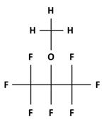 |
| Boiling point | 29 °C |
| Global warming potential | 363 |
Disclaimer/Publisher’s Note: The statements, opinions and data contained in all publications are solely those of the individual author(s) and contributor(s) and not of MDPI and/or the editor(s). MDPI and/or the editor(s) disclaim responsibility for any injury to people or property resulting from any ideas, methods, instructions or products referred to in the content. |
© 2024 by the authors. Licensee MDPI, Basel, Switzerland. This article is an open access article distributed under the terms and conditions of the Creative Commons Attribution (CC BY) license (https://creativecommons.org/licenses/by/4.0/).
Share and Cite
You, S.; Sun, E.; Chae, H.; Kim, C.-K. Effect of Discharge Gas Composition on SiC Etching in an HFE-347mmy/O2/Ar Plasma. Materials 2024, 17, 3917. https://doi.org/10.3390/ma17163917
You S, Sun E, Chae H, Kim C-K. Effect of Discharge Gas Composition on SiC Etching in an HFE-347mmy/O2/Ar Plasma. Materials. 2024; 17(16):3917. https://doi.org/10.3390/ma17163917
Chicago/Turabian StyleYou, Sanghyun, Eunjae Sun, Heeyeop Chae, and Chang-Koo Kim. 2024. "Effect of Discharge Gas Composition on SiC Etching in an HFE-347mmy/O2/Ar Plasma" Materials 17, no. 16: 3917. https://doi.org/10.3390/ma17163917
APA StyleYou, S., Sun, E., Chae, H., & Kim, C.-K. (2024). Effect of Discharge Gas Composition on SiC Etching in an HFE-347mmy/O2/Ar Plasma. Materials, 17(16), 3917. https://doi.org/10.3390/ma17163917