
Conductive Polymer-Based Electrodes and Supercapacitors: Materials, Electrolytes, and Characterizations


Abstract
1. Introduction
2. Supercapacitors Based on Conducting Polymers
- C: capacitance between two electrodes;
- A: area of the two surfaces of the electrodes that face each other;
- ε: dielectric constant of the electrolyte; and
- d: separation distance between two electrodes.
- Cp: positive electrode/electrolyte; and
- Cn: negative electrode/electrolyte.
- V0: lower potential limit (V);
- ΔV: potential window (V);
- I: current (A); and
- Δt: discharge time (s).
2.1. Electric Double-Layer Capacitors or EDLC Supercapacitors
2.2. Pseudo-Supercapacitors or Faradaic Supercapacitors
2.3. Hybrid Supercapacitors
3. Electrode Material
3.1. Conducting Polymers (CPs)
3.1.1. Polypyrrole
3.1.2. Polyaniline
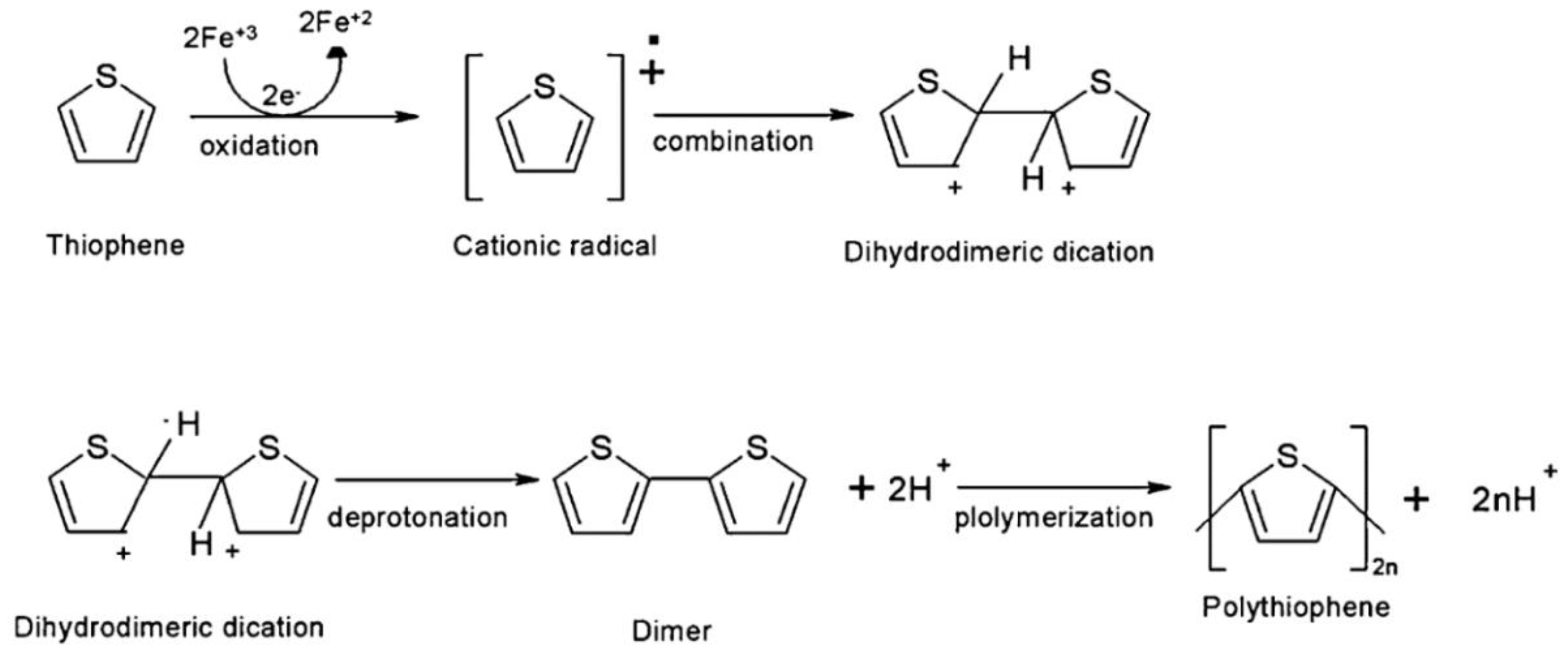
3.1.3. Polythiophene (PTh)
4. Electrode Arrangement: Two vs. Three Electrodes
4.1. Three-Electrode System
4.2. Two-Electrode System
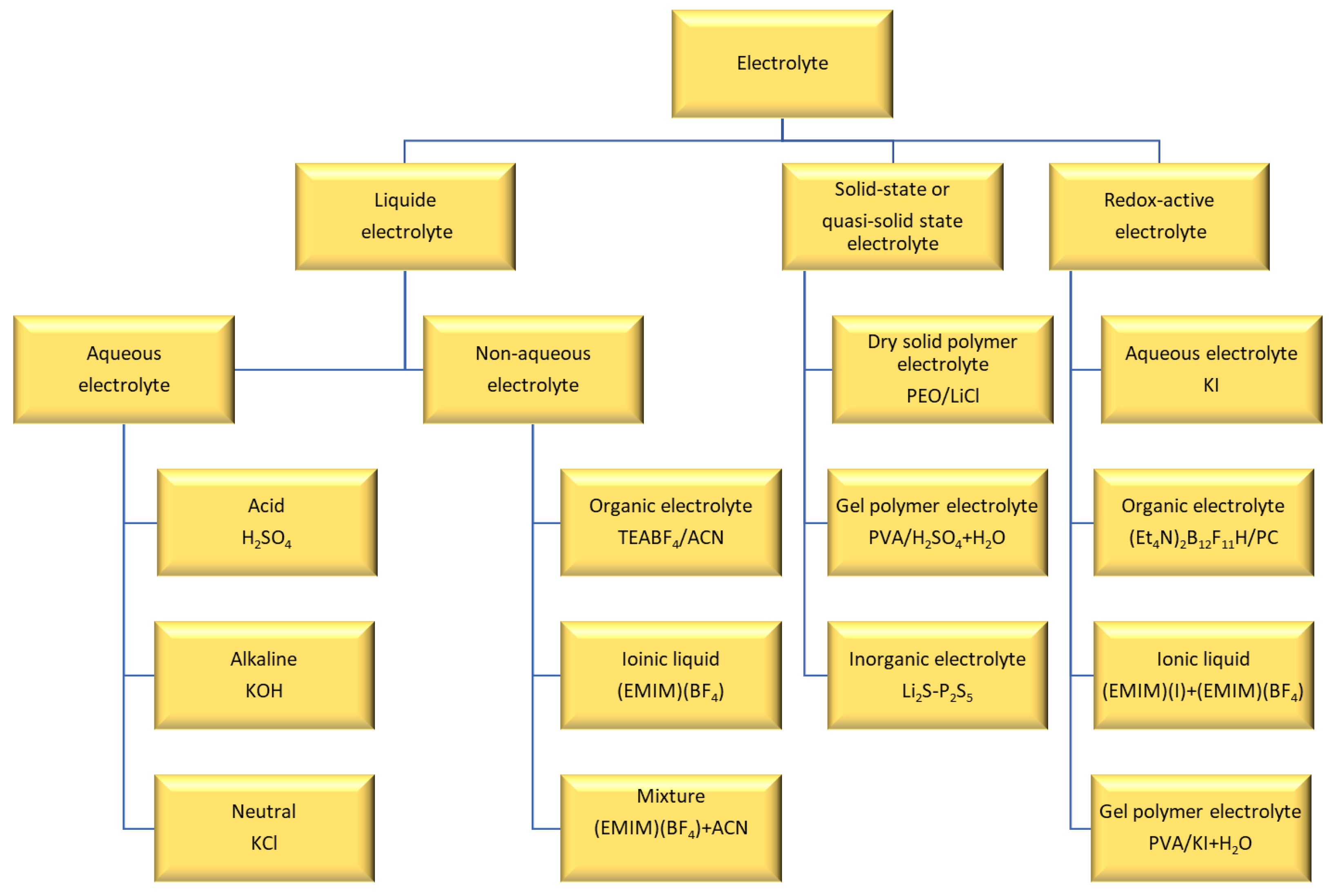
5. Electrolyte
5.1. Liquid Electrolyte

| Electrode Type | Electrolyte | Cell Voltage (V) | Specific Capacitance (F/g) | Energy Density (W h/kg) | Power Density (W/kg) | Temp. (°C) | Refs. |
|---|---|---|---|---|---|---|---|
| Mesoporous MnO2 | 0.65 M K2SO4 | 1 | 224.88 at 1 mV/s | 24.1 | 70 | RT | [135], 2012 |
| Mesoporous MnO2 | 1 M Li2SO4 | 1 | 284.24 at 1 mV/s | 28.8 | 70 | RT | [135] |
| Mesoporous MnO2 | 1 M Na2SO4 | 1 | 278.8 at 1 mV/s | 28.4 | 70 | RT | [135] |
| MnO2 nano flowers | 1 M LiOH | 0.6 | 363 at 2 mV/s | - | - | - | [136], 2015 |
| MnO2@carbon nanofibers composites | 0.5 M Na2SO4 | 0.85 | 551 at 2 mV/s (75 1C) | - | - | 0–75 | [137], 2013 |
| AC | 0.5 M Na2SO4 | 1.6 | 135 at 0.2 A/g | 10 | - | - | [133], 2010 |
| AC | 4 M NaNO3-EG | 2 | 22.3 at 2 mV/s | 14–16 | 500 | 0–60 | [138], 2014 |
| AC | 1 M NaNO3 | 1.6 | 116 at 2 mV/s | - | - | RT | [139], 2014 |
| AC | Na2SO4/0.5 M | 1.6 | 135 at 0.2 A/g | 10 | - | - | [133] |
| AC fibers | 1 M H2SO4 | 0.9 | 280 at 0.5 A/g | - | - | RT | [140], 2014 |
| PANi-grafted rGO/AC | 1 M H2SO4 | 0.8 | 1045.51 at 0.2 A/g | 8.3 | 60,000 | - | [141], 2014 |
| Graphene/mPANi | 1 M H2SO4 | 0.7 | 749 at 0.5 A/g | 11.3 | 106.7 | - | [142], 2014 |
| PPy thin films | 0.5 M H2SO4 | 1 | 510 at 0.25 mA/cm2 | 133 | 758 | - | [143], 2014 |
| Pristine flexible PPy membrane | Solid PVA/H2SO4/EG | 0.7 | 191.7 at 0.5 A/g | 14.1 | 181.9 | RT | [144], 2021 |
| Electrode Material | Electrolyte | Cell Voltage (V) | Specific Capacitance (F/g) | Power Density (W/Kg) | Energy Density (Wh/Kg) | Temp. (°C) | Refs. |
|---|---|---|---|---|---|---|---|
| Electrode materials in double layer supercapacitors | |||||||
| AC | 1.5 M SBPBF4/PC | 3.5 | 122 at 0.1 A/g | - | 52 | RT | [150], 2014 |
| AC | 1.6 M TEAODFB/PC | 2.5 | 21.4 at 1 A/g | ~1000 | 28 (20 °C) | −40 to 60 | [151], 2012 |
| AC | 0.7 M TEABF4/ADN | 3.75 | 25 at 20 mV/s | - | 28 | RT | [152], 2012 |
| AC | 1 M TEABF4/HFIP | - | 110 at 1 mV/s | - | - | - | [153], 2012 |
| Microporous carbide derived carbon | 1 M NaPF6/(EC-DMC-PC-EA 1:1:1:0.5) | 3.4 | 120 at 1 mV/s | ~90 | ~40 | −40 to 60 | [154], 2014 |
| Highly porous interconnected carbon nanosheets | 1 M TEABF4/ACN | 2.7 | B120-150 at 1 mV/s | 25,000-27,000 | 25 | - | [155], 2014 |
| Heteroatom doped porous carbon flakes | M LiPF6/(EC-DEC 1:1) | 3 | 126 at 1 A/g | 2243 | 29 | RT | [156], 2014 |
| Carbon (provided by Batscap) | 1 M SBPBF4/ACN | 2.3 | 109 | - | - | −30 to 60 | [157], 2013 |
| Graphene-CNT composite | 1 M TEABF4/PC | 3 | 110 at 1 A/g | 400 | 34.3 | - | [158], 2013 |
| Microporous TiC-CDC | 1 M TEMABF4/(PC-PS 95:5) | 2.7 | 100 at 10 mV/s (60 1C) | ~1000 | ~25–27 | −40 to 60 | [159], 2014 |
| Electrode materials in pesedoucapacitors | |||||||
| PANi/graphite | 0.5 M LiClO4/PC | 1 | ~420 at 50 mV/s | - | - | RT | [160], 2013 |
| MoO3 nanosheets | 1 M LiClO4/PC | - | 540 at 0.1 mV/s | - | - | - | [147], 2010 |
| Nanoporous Co3O4 -graphene composite | 1 M LiPF6/(EC-DEC 1:1) | - | 424.2 at 1 A/g | - | - | RT | [161], 2014 |
| Heterostructured poly (3,6-dithien-2-yl-9H-carbazol-9-yl acetic acid)/TiO2 nanoparticles composite | 0.5 M Bu4NBF4/ACN | 1.2 | 462.88 at 2.5 mA/cm2 | - | 89.98 | RT | [162], 2014 |
5.2. Solid and Quasi-Solid Electrolytes
5.3. Redox-Active Electrolytes
5.4. Self-Healing Electrolytes
6. Characterization Methods
6.1. Electrochemical Analysis
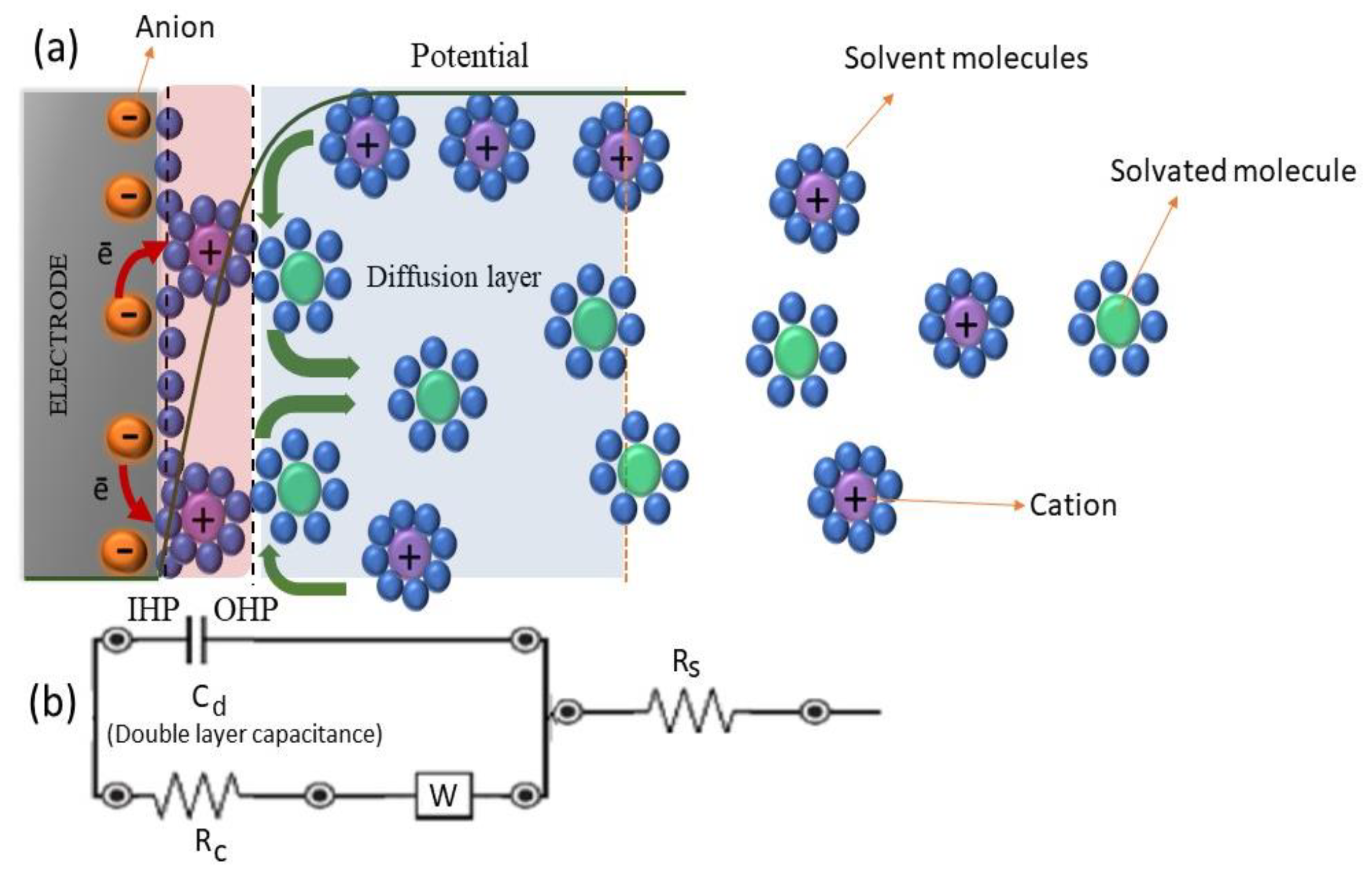
6.1.1. Electrochemical Impedance Spectroscopy (EIS)
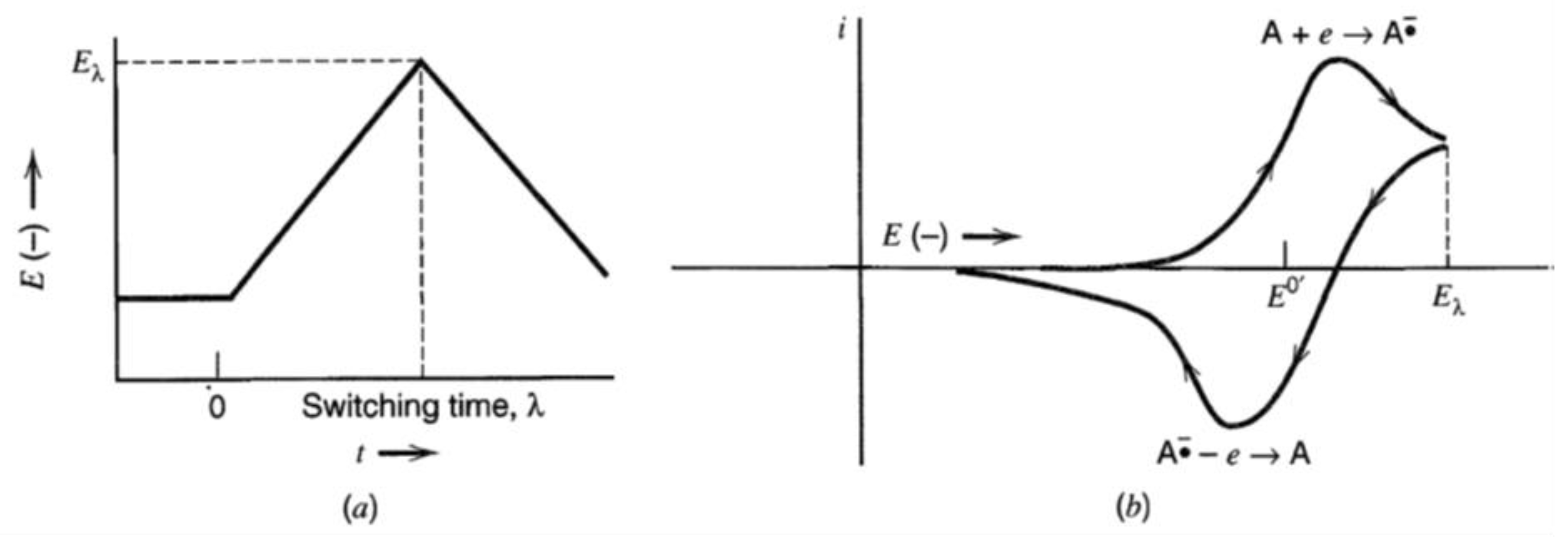
6.1.2. Cyclic Voltammetry
- v: scan rate (v/s);
- Eλ: switching potential;
- Ei: initial potential; and
- λ: run time at switching potential.
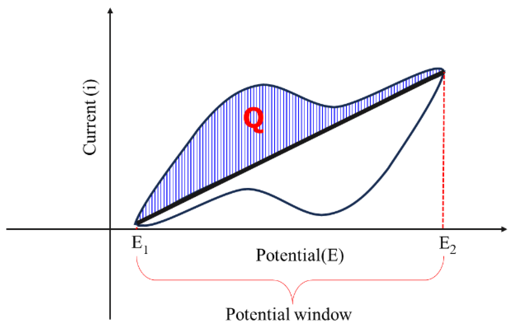
6.1.3. Cyclic Charge–Discharge (CCD)
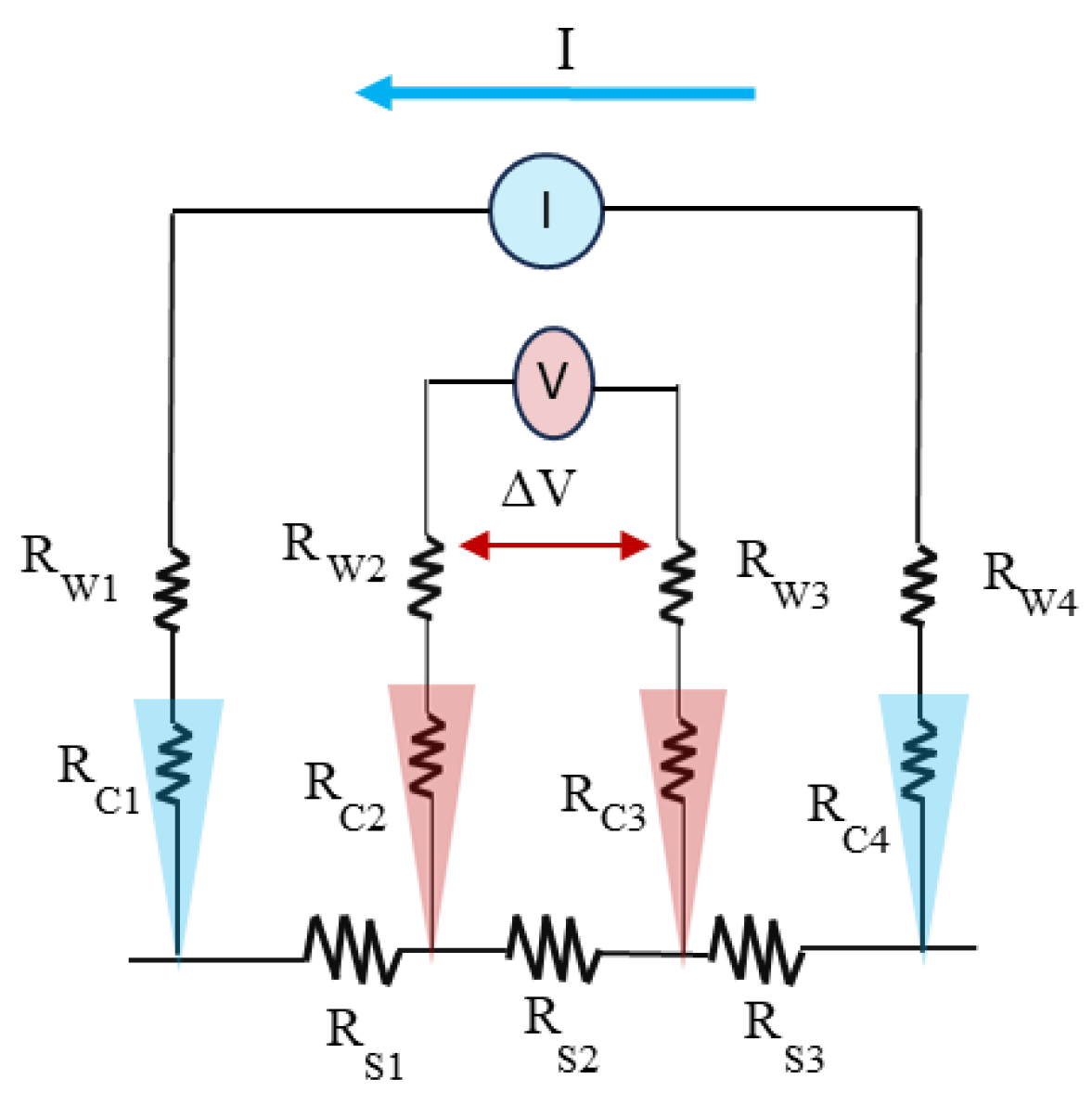
6.2. Four-Point Probe for Resistivity Measurement
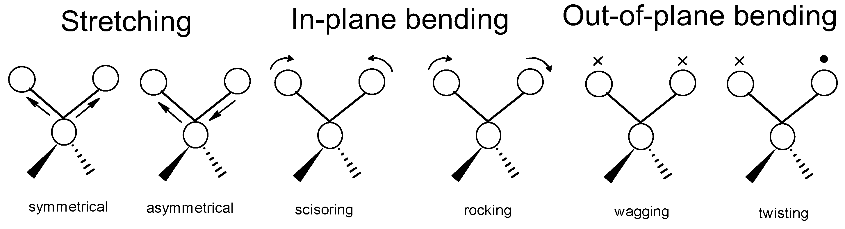
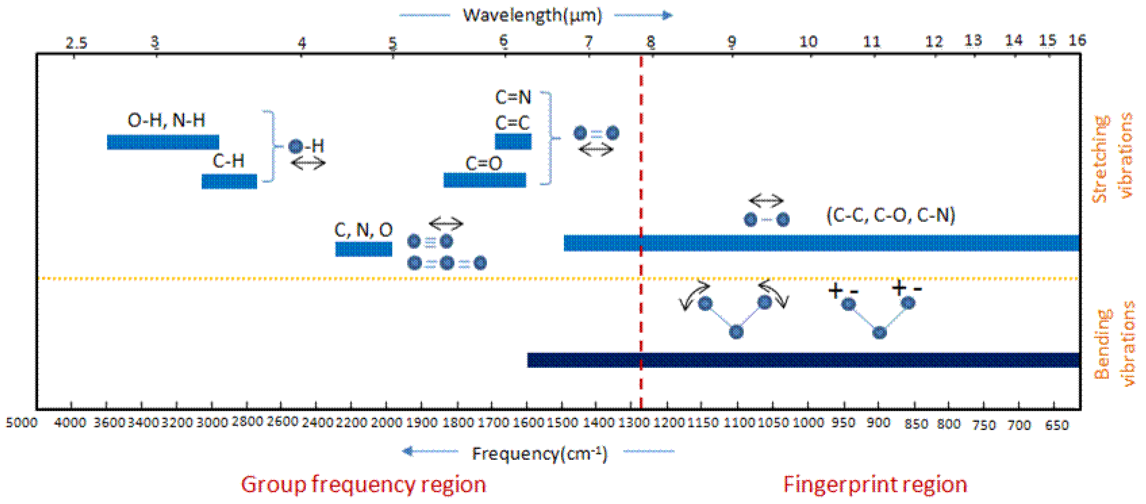
6.3. Infrared Spectroscopy
6.4. X-ray Photoelectron Spectroscopy (XPS)
6.5. Scanning Electron Microscopy (SEM)
7. Conclusions
Author Contributions
Funding
Data Availability Statement
Conflicts of Interest
References
- Chen, C.; Zhang, Y.; Li, Y.; Dai, J.; Song, J.; Yao, Y.; Gong, Y.; Kierzewski, I.; Xie, J.; Hu, L. All-wood, low tortuosity; aqueous, biodegradable supercapacitors with ultra-high capacitance. Energy Environ. Sci. 2017, 10, 538–545. [Google Scholar]
- Kumar, N.; Kim, S.B.; Lee, S.Y.; Park, S.J. Recent advanced supercapacitor: A Review of storage mechanisms, electrode materials, modification, and perspectives. Nanomaterials 2022, 12, 3708. [Google Scholar] [CrossRef]
- Ahmed, S.; Ahmed, A.; Basha, B.; Hussain, S.; Uddin, I.; Gondal, M.A. Critical review on recent developments in conducting polymer nanocomposites for supercapacitors. Synth. Met. 2023, 295, 117326. [Google Scholar]
- Hao, L.; Yu, D. Progress of conductive polypyrrole nanocomposites. Synth. Met. 2022, 290, 117138. [Google Scholar]
- Majeed, A.H.; Mohammed, L.A.; Hammoodi, O.G.; Sehgal, S.; Alheety, M.A.; Saxena, K.K.; Dadoosh, S.A.; Mohammed, I.K.; Jasim, M.M.; Salmaan, N.U. A review on polyaniline: Synthesis, properties, nanocomposites, and electrochemical applications. Int. J. Polym. Sci. 2022, 2022, 19. [Google Scholar]
- Poonam, K.; Sharma, A.; Arora, S.K. Tripathi. Review of supercapacitors: Materials and devices. J. Energy Storage 2019, 21, 801–825. [Google Scholar]
- Libich, J.; Máca, J.; Vondrák, J.; Čech, O.; Sedlaříková, M. Supercapacitors: Properties and applications. J. Energy Storage 2018, 17, 224–227. [Google Scholar]
- REN21. Renewable Energy Policy Network for 21st Century, Renewables 2016 Global Status Report; REN21: Paris, France, 2016; ISBN 978-3-9818107-0-7. [Google Scholar]
- Wu, Z.S.; Winter, A.; Chen, L.; Sun, Y.; Turchanin, A.; Feng, X.; Müllen, K. Three-dimensional nitrogen and boron co-doped graphene for high-performance all-solid-state supercapacitors. Adv. Mater. 2012, 24, 5130–5135. [Google Scholar]
- Lu, X.; Wang, G.; Zhai, T.; Yu, M.; Xie, S.; Ling, Y.; Liang, C.; Tong, Y.; Li, Y. Stabilized TiN nanowire arrays for high-performance and flexible supercapacitors. Nano Lett. 2012, 12, 5376–5381. [Google Scholar]
- Armand, M.; Endres, F.; MacFarlane, D.E.; Ohno, H.; Scrosati, B. Ionic-liquid materials for the electrochemical challenges of the future. Nat. Mater. 2009, 8, 621–629. [Google Scholar]
- Van Aken, K.L.; Beidaghi, M.; Gogotsi, Y. Formulation of ionic-liquid electrolyte to expand the voltage window of supercapacitors. Angew. Chem. Int. Ed. 2015, 54, 4806–4809. [Google Scholar]
- Zhong, C.; Deng, Y.; Hu, W.; Qiao, J.; Zhang, L.; Zhang, J. A review of electrolyte materials and compositions for electrochemical supercapacitors. Chem. Soc. Rev. 2015, 44, 7484–7539. [Google Scholar] [PubMed]
- Wu, Q.; He, T.; Zhang, Y.; Zhang, J.; Wang, Z.; Liu, Y.; Zhao, L.; Wu, Y.; Ran, F. Cyclic stability of supercapacitors: Materials, energy storage mechanism, test methods, and device. J. Mater. Chem. A 2021, 9, 24094–24147. [Google Scholar]
- Zhang, K.; Zhang, L.L.; Zhao, X.S.; Wu, J. Graphene/polyaniline nanofiber composites as supercapacitor electrodes. Chem. Mater. 2010, 22, 1392–1401. [Google Scholar]
- Antiohos, D.; Folkes, G.; Sherrell, P.; Ashraf, S.; Wallace, G.G.; Aitchison, P.; Harris, A.T.; Chen, J.; Minett, A.I. Compositional effects of PEDOT-PSS/single walled carbon nanotube films on supercapacitor device performance. J. Mater. Chem. 2011, 21, 15987–15994. [Google Scholar]
- Zhu, M.; Huang, Y.; Deng, Q.; Zhou, J.; Pei, Z.; Xue, Q.; Huang, Y.; Wang, Z.; Li, H.; Huang, Q.; et al. Highly flexible, freestanding supercapacitor electrode with enhanced performance obtained by hybridizing polypyrrole chains with MXene. Adv. Energy Mater. 2016, 6, 1600969. [Google Scholar]
- Ghosh, S.; Inganäs, O. Conducting polymer hydrogels as 3D electrodes: Applications for supercapacitors. Adv. Mater. 1999, 11, 1214–1218. [Google Scholar]
- Chen, T.; Peng, H.; Durstock, M.; Dai, L. High-performance transparent and stretchable all-solid supercapacitors based on highly aligned carbon nanotube sheets. Sci. Rep. 2014, 4, 3612. [Google Scholar]
- Zang, X.; Zhu, M.; Li, X.; Li, X.; Zhen, Z.; Lao, J.; Wang, K.; Kang, F.; Wei, B.; Zhu, H. Dynamically stretchable supercapacitors based on graphene woven fabric electrodes. Nano Energy. 2015, 15, 83–91. [Google Scholar]
- Wang, S.; Liu, N.; Su, J.; Li, L.; Long, F.; Zou, Z.; Jiang, X.; Gao, Y. Highly stretchable and self-healable supercapacitor with reduced graphene oxide based fiber springs. ACS Nano 2017, 11, 2066–2074. [Google Scholar]
- Wang, Z.; Zhu, M.; Pei, Z.; Xue, Q.; Li, H.; Huang, Y.; Zhi, C. Polymers for supercapacitors: Boosting the development of the flexible and wearable energy storage. Mater. Sci. Eng. R Rep. 2020, 139, 100520. [Google Scholar]
- Chatterjee, D.P.; Nandi, A.K. A review on the recent advances in hybrid supercapacitors. J. Mater. Chem. A 2021, 9, 15880. [Google Scholar]
- Wang, G.; Zhang, L.; Zhang, J. A review of electrode materials for electrochemical supercapacitors. Chem. Soc. Rev. 2012, 41, 797–828. [Google Scholar]
- Pattananuwat, P.; Aht-ong, D. Controllable morphology of polypyrrole wrapped graphene hydrogel framework composites via cyclic voltammetry with aiding of poly (sodium 4-styrene sulfonate) for the flexible supercapacitor electrode. Electrochim. Acta 2017, 224, 149–160. [Google Scholar]
- Fu, D.; Li, H.; Zhang, X.M.; Han, G.; Zhou, H.; Chang, Y. Flexible solid-state supercapacitor fabricated by metal-organic framework/graphene oxide hybrid interconnected with PEDOT. Mater. Chem. Phys. 2016, 79, 166–173. [Google Scholar]
- Conway, B.E. Transition from “Supercapacitor” to “Battery” Behavior in Electrochemical Energy Storage. J. Electrochem. Soc. 1991, 138, 1539. [Google Scholar]
- Han, G.; Liu, Y.; Zhang, L.; Kan, E.; Zhang, S.; Tang, J.; Tang, W. MnO2 nanorods intercalating graphene oxide/polyaniline ternary composites for robust high-performance supercapacitors. Sci. Rep. 2014, 4, 4824. [Google Scholar]
- Zhou, C.; Zhang, Y.; Li, Y.; Liu, J. Construction of high-capacitance 3D CoO@Polypyrrole nanowire array electrode for aqueous asymmetric supercapacitor. Nano Lett. 2013, 13, 2078–2085. [Google Scholar]
- Zhang, Y.; Feng, H.; Wu, X.; Wang, L.; Zhang, A.; Xia, T.; Dong, H.; Li, X.; Zhang, L. Progress of electrochemical capacitor electrode materials: A review. Int. J. Hydrogen Energy 2009, 34, 4889–4899. [Google Scholar]
- Conway, B.E.; Birss, V.; Wojtowicz, J. The role and utilization of pseudocapacitance for energy storage by supercapacitors. J. Power Sources 1997, 66, 1–14. [Google Scholar]
- Mensah-Darkwa, K.; Zequine, C.; Kahol, P.K.; Gupta, R.K. Supercapacitor energy storage device using biowastes: A sustainable approach to green energy. Sustainability 2019, 11, 414. [Google Scholar] [CrossRef]
- Yu, G.; Xie, X.; Pan, L.; Bao, Z.; Cui, Y. Hybrid nanostructured materials for high-performance electrochemical capacitors. Nano Energy 2013, 2, 213–234. [Google Scholar]
- Miller, J.R.; Simon, P. Fundamentals of electrochemical capacitor design and operation. Electrochem. Soc. Interface. 2008, 17, 31–32. [Google Scholar]
- Zheng, Y.; Yang, Y.; Chen, S.; Yuan, Q. Smart, stretchable and wearable supercapacitors: Prospects and challenges. CrystEngComm 2016, 18, 4218–4235. [Google Scholar]
- Wang, Y.; Zhu, C.; Pfattner, R.; Yan, H.; Jin, L.; Chen, S.; Molina-Lopez, F.; Lissel, F.; Liu, J.; Rabiah, N.I.; et al. A highly stretchable, transparent, and conductive polymer. Sci. Adv. 2017, 3, 1602076. [Google Scholar] [CrossRef]
- Lota, K.; Khomenko, V.; Frackowiak, E. Frackowiak. Capacitance properties of poly(3,4-ethylenedioxythiophene)/carbon nanotubes composites. J. Phys. Chem. Solids 2004, 13, 2419. [Google Scholar] [CrossRef]
- Snook, G.A.; Kao, P.; Best, A.S. Conducting-polymer-based supercapacitor devices and electrodes. J. Power Sources 2011, 196, 1–12. [Google Scholar] [CrossRef]
- Janata, J.; Josowicz, M. Conducting polymers in electronic chemical sensors. Nat. Mater. 2003, 2, 19–24. [Google Scholar] [CrossRef] [PubMed]
- Sadki, S.; Schottland, P.; Brodie, N.; Sabouraud, G. The mechanisms of pyrrole electropolymerization. Chem. Soc. Rev. 2000, 29, 283–293. [Google Scholar]
- Lee, K.; Cho, S.; Sung, H.P.; Heeger, A.J.; Lee, C.W.; Lee, S.H. Metallic transport in polyaniline. Nature 2006, 441, 65–68. [Google Scholar] [CrossRef]
- Peng, C.; Hu, D.; Chen, G.Z. Theoretical specific capacitance based on charge storage mechanisms of conducting polymers: Comment on “Vertically oriented arrays of polyaniline nanorods and their super electrochemical properties”. Chem. Commun. 2011, 47, 4105–4107. [Google Scholar] [CrossRef]
- Zang, J.; Bao, S.J.; Li, C.M.; Bian, H.; Cui, X.; Bao, Q.; Sun, C.Q.; Guo, J.; Lian, K. Well-aligned cone-shaped nanostructure of polypyrrole/RuO2 and its electrochemical supercapacitor. J. Phys. Chem. C 2008, 112, 14843–14847. [Google Scholar] [CrossRef]
- Bobacka, J.; Lewenstam, A.; Ivaska, A. Electrochemical impedance spectroscopy of oxidized poly(3,4-ethylenedioxythiophene) film electrodes in aqueous solutions. J. Electroanal. Chem. 2000, 88, 423–429. [Google Scholar] [CrossRef]
- Wallace, G.G.; Teasdale, P.R.; Spinks, G.M.; Kane-Maguire, L.A.P. Conductive Electroactive Polymers: Intelligent Materials Systems, 2nd ed.; CRC Press: Boca Raton, FL, USA, 2003. [Google Scholar] [CrossRef]
- Chen, Y.; Du, L.; Yang, P.; Sun, P.; Yu, X.; Mai, W. Significantly enhanced robustness and electrochemical performance of flexible carbon nanotube-based supercapacitors by electrodepositing polypyrrole. J. Power Sources 2015, 287, 68–74. [Google Scholar] [CrossRef]
- Qian, T.; Yu, C.; Wu, S.; Shen, J. A facilely prepared polypyrrole-reduced graphene oxide composite with a crumpled surface for high performance supercapacitor electrodes. J. Mater. Chem. A 2013, 1, 6539–6542. [Google Scholar] [CrossRef]
- Wang, K.; Wu, H.; Meng, Y.; Wei, Z. Conducting polymer nanowire arrays for high performance supercapacitors. Small 2014, 10, 14–31. [Google Scholar] [CrossRef]
- Villarreal, I.; Morales, E.; Otero, T.F.; Acosta, J.L. Electropolymerization kinetics of pyrrole in aqueous solution on graphite felt electrodes. Synth. Met. 2001, 123, 487–492. [Google Scholar] [CrossRef]
- Thomas, O.D.; Peckham, T.J.; Thanganathan, U.; Yang, Y.; Holdcroft, S. Sulfonated polybenzimidazoles: Proton conduction and acid-base crosslinking. J. Polym. Sci. Part A Polym. Chem. 2010, 48, 3640–3650. [Google Scholar] [CrossRef]
- Cadby, A.J.; Yang, C.; Holdcroft, S.; Bradley, D.D.C.; Lane, P.A. Limiting intersystem crossing in conjugated polymers by molecular design. Adv. Mater. 2002, 14, 57–60. [Google Scholar] [CrossRef]
- Thomas, R.; Durix, S.; Sinturel, C.; Omonov, T.; Goossens, S.; Groeninckx, G.; Moldenaers, P.; Thomas, S. Cure kinetics, morphology and miscibility of modified DGEBA-based epoxy resin—Effects of a liquid rubber inclusion. Polymer 2007, 48, 1695–1710. [Google Scholar] [CrossRef]
- Tan, Y.; Ghandi, K. Kinetics and mechanism of pyrrole chemical polymerization. Synth. Met. 2013, 175, 183–191. [Google Scholar] [CrossRef]
- Zhang, L.; Meng, S.; Zhang, Z. Electroactivity and stability of polylactide/polypyrrole composites. J. Biomater. Sci. Polym. Ed. 2011, 22, 1931–1946. [Google Scholar] [CrossRef]
- Shirakawa, H. The discovery of polyacetylene Film: The dawning of an era of conducting polymers (Nobel lecture)—Die Entdeckung der Polyacetylenfilme—Der Beginn des Zeitalters leitfähiger Polymere (Nobel-Aufsatz). Angew. Chem. Int. Ed. 2001, 14, 2574–2580. [Google Scholar]
- MacDiarmid, A.G.; Mammone, R.J.; Kaner, R.B.; Porter, S.J. The concept of ‘doping’ of conducting polymers: The role of reduction potentials. Philos. Trans. R. Soc. Lond. A 1985, 314, 3–15. [Google Scholar] [CrossRef]
- Nalwa, H.S. Handbook of Organic Conductive Molecules and Polymers, Volume 2, Conductive Polymers: Synthesis and Electrical Properties; Volume 2 Edition; Wiley: Hoboken, NJ, USA, 1997. [Google Scholar]
- Shown, I.; Ganguly, A.; Chen, L.C.; Chen, K.H. Conducting polymer-based flexible supercapacitor. Energy Sci. Eng. 2015, 3, 2–26. [Google Scholar] [CrossRef]
- Paul, R.K.; Pillai, C.K.S. Melt/solution processable conducting polyaniline with novel sulfonic acid dopants and its thermoplastic blends. Synth. Met. 2000, 114, 27–35. [Google Scholar] [CrossRef]
- Higgins, S.J. Conjugated polymers incorporating pendant functional groups—Synthesis and characterisation. Chem. Soc. Rev. 1997, 26, 247–257. [Google Scholar] [CrossRef]
- King, G.; Higgins, S.J. Synthesis and characterisation of novel substituted benzo[c]thiophenes and polybenzo[c]thiophenes: Tuning the potentials for n- and p-doping in transparent conducting polymers. J. Mater. Chem. 1995, 30, 305. [Google Scholar]
- Liu, J.; Yang, R. Tuning the thermal conductivity of polymers with mechanical strains. Phys. Rev. B Condens. Matter Mater. Phys. 2010, 81, 174122. [Google Scholar] [CrossRef]
- Mithra, L.M.M.; Cao, Y.; Cho, S.; Sutar, D.; Lee, K.; Menon, R.; Subramanyam, S.V. Electrical transport and reflectance studies on polypyrrole-CF3SO3- in the vicinity of metal-insulator transition. Synth. Met. 2001, 119, 437–438. [Google Scholar] [CrossRef]
- Malhotra, B.D.; Singhal, R. Conducting polymer based biomolecular electronic devices. Pramana J. Phys. 2003, 61, 331–343. [Google Scholar] [CrossRef]
- Rohwerder, M.; Michalik, A. Conducting polymers for corrosion protection: What makes the difference between failure and success? Electrochim. Acta 2007, 53, 1300–1313. [Google Scholar] [CrossRef]
- Mahmud, H.N.M.E.; Kassim, A.; Zainal, Z.; Yunus, W.M.M. Electrochemical formation of polypyrrole-carboxymethylcellulose conducting polymer composite films. J. Mater. Sci. Technol. 2005, 21, 661–665. [Google Scholar]
- Othman, N.; Talib, Z.A.; Kassim, A.; Shaari, A.H.; Liew, J.Y.C. Electrical properties of polypyrrole conducting polymer at various dopant concentrations. Malays. J. Fundam. Appl. Sci. 2009, 5, 29–33. [Google Scholar] [CrossRef]
- Shaktawat, V.; Jain, N.; Saxena, R.; Saxena, N.S.; Sharma, K.; Sharma, T.P. Temperature dependence of electrical conduction in pure and doped polypyrrole. Polym. Bull. 2006, 57, 535–543. [Google Scholar]
- Mofdal, M.E.; Al-Jumaili, B.E.; Talib, Z.A.; Muh’d, I.B.; Tagbo, M. The evaluation of temperature effect on peak-to-peak line width (ΔHpp) of conjugating polymer polypyrrole (Ppy). J. Phys. Conf. Ser. 2019, 1178, 012021. [Google Scholar] [CrossRef]
- Lima, M.P.; Magela, E.; Silva, G. Dynamical evolution of polaron to bipolaron in conjugated polymers. Phys. Rev. B Condens. Matter Mater. Phys. 2006, 74, 14–16. [Google Scholar] [CrossRef]
- Xie, S.; Mei, L.; Lin, D.L. Transition between bipolaron and polaron states in doped heterocycle polymers. Phys. Rev. B 1994, 50, 13364. [Google Scholar]
- De Oliveira, J.R.; Silva, G.M.E. Interchain interaction effects on polaron-bipolaron transition on conducting polymers. J. Mater. Sci. 2008, 43, 585–590. [Google Scholar] [CrossRef]
- Molapo, K.M.; Ndangili, P.M.; Ajayi, R.F.; Mbambisa, G.; Mailu, S.M.; Njomo, N.; Masikini, M.; Baker, P.; Iwuoha, E.I. Electronics of conjugated polymers (I): Polyaniline. Int. J. Electrochem. Sci. 2012, 7, 11859–11875. [Google Scholar] [CrossRef]
- Namsheer, K.; Rout, C.S. Conducting polymers: A comprehensive review on recent advances in synthesis, properties and applications. RSC Adv. 2021, 11, 5659–5697. [Google Scholar] [CrossRef]
- Wu, C.Q.; Sun, X. Nonlinear optical properties of conducting polymers. Synth. Met. 1991, 43, 3213–3216. [Google Scholar] [CrossRef]
- Navathe, G.J.; Prasad, S.R.; Mane, A.M.; Barge, S.H.; Dongale, T.D.; Shaikh, V.; Karanjkar, M.M.; Teli, S.B.; Patil, P.S.; Prasad, N.R. A critical review on design and development of new generation energy storage devices. ES Energy Environ. 2022, 17, 11–32. [Google Scholar] [CrossRef]
- Liu, H.; Wang, Y.; Gou, X.; Qi, T.; Yang, J.; Ding, Y. Three-dimensional graphene/polyaniline composite material for high-performance supercapacitor applications. Mater. Sci. Eng. B Solid-State Mater. Adv. Technol. 2013, 178, 293–298. [Google Scholar] [CrossRef]
- Gobal, F.; Faraji, M. Electrodeposited polyaniline on Pd-loaded TiO2 nanotubes as active material for electrochemical supercapacitor. J. Electroanal. Chem. 2013, 691, 51–56. [Google Scholar] [CrossRef]
- Eftekhari, A.; Li, L.; Yang, Y. Polyaniline supercapacitors. J. Power Source 2017, 347, 86–107. [Google Scholar] [CrossRef]
- Bian, C.; Yu, A. De-doped polyaniline nanofibres with micropores for high-rate aqueous electrochemical capacitor. Synth. Met. 2010, 160, 1579–1583. [Google Scholar] [CrossRef]
- Wu, W.; Pan, D.; Li, Y.; Zhao, G.; Jing, L.; Chen, S. Facile fabrication of polyaniline nanotubes using the self-assembly behavior based on the hydrogen bonding: A mechanistic study and application in high-performance electrochemical supercapacitor electrode. Electrochim. Acta 2015, 152, 126–134. [Google Scholar] [CrossRef]
- Gawli, Y.; Banerjee, A.; Dhakras, D.; Deo, M.; Bulani, D.; Wadgaonkar, P.; Shelke, M.; Ogale, S. 3D polyaniline architecture by concurrent inorganic and organic acid doping for superior and robust high rate supercapacitor performance. Sci. Rep. 2016, 6, 21002. [Google Scholar] [CrossRef]
- Giri, S.; Ghosh, D.; Das, C.K. In situ synthesis of cobalt doped polyaniline modified graphene composites for high performance supercapacitor electrode materials. J. Electroanal. Chem. 2013, 697, 32–45. [Google Scholar] [CrossRef]
- Yang, Z.; Peng, H.; Wang, W.; Liu, T. Crystallization behavior of poly(ε-caprolactone)/layered double hydroxide nanocomposites. J. Appl. Polym. Sci. 2010, 116, 2658–2667. [Google Scholar] [CrossRef]
- Grover, S.; Goel, S.; Marichi, R.B.; Sahu, V.; Singh, G.; Sharma, R.K. Polyaniline all solid-state pseudocapacitor: Role of morphological variations in performance evolution. Electrochim. Acta 2016, 196, 131–139. [Google Scholar] [CrossRef]
- Sharma, V.; Sahoo, A.; Sharma, Y.; Mohanty, P. Synthesis of nanoporous hypercrosslinked polyaniline (HCPANI) for gas sorption and electrochemical supercapacitor applications. RSC Adv. 2015, 5, 45749–45754. [Google Scholar] [CrossRef]
- Fan, L.Z.; Hu, Y.S.; Maier, J.; Adelhelm, P.; Smarsly, B.; Antonietti, M. High electroactivity of polyaniline in supercapacitors by using a hierarchically porous carbon monolith as a support. Adv. Funct. Mater. 2007, 17, 3083–3087. [Google Scholar] [CrossRef]
- Cho, S.; Shin, K.H.; Jang, J. Enhanced electrochemical performance of highly porous supercapacitor electrodes based on solution processed polyaniline thin films. ACS Appl. Mater. Interfaces. 2013, 5, 9186–9193. [Google Scholar] [CrossRef]
- Rajagopalan, B.; Hur, S.H.; Chung, J.S. Surfactant-treated graphene covered polyaniline nanowires for supercapacitor electrode. Nanoscale Res. Lett. 2015, 10, 1–9. [Google Scholar] [CrossRef]
- Miao, Y.E.; Fan, W.; Chen, D.; Liu, T. High-performance supercapacitors based on hollow polyaniline nanofibers by electrospinning. ACS Appl. Mater. Interfaces. 2013, 5, 4423–4428. [Google Scholar] [CrossRef] [PubMed]
- Eftekhari, A. Synthesis of nanostructured large particles of polyaniline. J. Appl. Polym. Sci. 2006, 102, 6060–6063. [Google Scholar] [CrossRef]
- Mujawar, S.H.; Ambade, S.B.; Battumur, T.; Ambade, R.B.; Lee, S.H. Electropolymerization of polyaniline on titanium oxide nanotubes for supercapacitor application. Electrochim. Acta 2011, 56, 4462–4466. [Google Scholar] [CrossRef]
- Eftekhari, A. (Ed.) Nanostructured Conductive Polymers; Wiley: Hoboken, NJ, USA, 2010. [Google Scholar] [CrossRef]
- Uppugalla, S.; Male, U.; Srinivasan, P. Design and synthesis of heteroatoms doped carbon/polyaniline hybrid material for high performance electrode in supercapacitor application. Electrochim. Acta 2014, 146, 242–248. [Google Scholar] [CrossRef]
- Liu, T.; Finn, L.; Yu, M.; Wang, H.; Zhai, T.; Lu, X.; Tong, Y.; Li, Y. Polyaniline and polypyrrole pseudocapacitor electrodes with excellent cycling stability. Nano Lett. 2014, 14, 2522–2527. [Google Scholar] [CrossRef]
- Yan, Y.; Cheng, Q.; Wang, G.; Li, C. Growth of polyaniline nanowhiskers on mesoporous carbon for supercapacitor application. J. Power Sources 2011, 169, 7835–7840. [Google Scholar] [CrossRef]
- Woo, S.W.; Dokko, K.; Nakano, H.; Kanamura, K. Incorporation of polyaniline into macropores of three-dimensionally ordered macroporous carbon electrode for electrochemical capacitors. J. Power Sources 2009, 190, 596–600. [Google Scholar] [CrossRef]
- Moussa, M.; El-Kady, M.F.; Zhao, Z.; Majewski, P.; Ma, J. Recent progress and performance evaluation for polyaniline/graphene nanocomposites as supercapacitor electrodes. Nanotechnology 2016, 27, 442001. [Google Scholar] [CrossRef]
- Jo, S.; Park, Y.H.; Ha, S.G.; Kim, S.M.; Song, C.; Park, S.Y.; In, I. Simple noncovalent hybridization of polyaniline with graphene and its application for pseudocapacitor. Synth. Met. 2015, 209, 60–67. [Google Scholar] [CrossRef]
- Li, Y.; Zhao, X.; Yu, P.; Zhang, Q. Oriented arrays of polyaniline nanorods grown on graphite nanosheets for an electrochemical supercapacitor. Langmuir 2013, 29, 493–500. [Google Scholar] [CrossRef] [PubMed]
- Jaidev; Jafri, R.I.; Mishra, A.K.; Ramaprabhu, S. Polyaniline-MnO2 nanotube hybrid nanocomposite as supercapacitor electrode material in acidic electrolyte. J. Mater. Chem. 2011, 21, 17601–17605. [Google Scholar] [CrossRef]
- Eftekhari, A.; Molaei, F. Carbon nanotube-assisted electrodeposition. Part I: Battery performance of manganese oxide films electrodeposited at low current densities. J. Power Sources 2015, 274, 1306–1314. [Google Scholar] [CrossRef]
- Eftekhari, A.; Molaei, F. Carbon nanotube-assisted electrodeposition. Part II: Superior pseudo-capacitive behavior of manganese oxide film electrodeposited at high current densities. J. Power Sources 2015, 274, 1315–1321. [Google Scholar] [CrossRef]
- Mu, B.; Zhang, W.; Shao, S.; Wang, A. Glycol assisted synthesis of graphene-MnO2-polyaniline ternary composites for high performance supercapacitor electrodes. Phys. Chem. Chem. Phys. 2014, 16, 7872–7880. [Google Scholar] [CrossRef]
- Lu, K.; Jiang, R.; Gao, X.; Ma, H. Fe3O4/carbon nanotubes/polyaniline ternary composites with synergistic effects for high performance supercapacitors. RSC Adv. 2014, 4, 52393–52401. [Google Scholar] [CrossRef]
- Eftekhari, A. Glycerol biosensor based on glycerol dehydrogenase incorporated into polyaniline modified aluminum electrode using hexacyanoferrate as mediator. Sens. Actuators B Chem. 2001, 80, 283–289. [Google Scholar] [CrossRef]
- Eftekhari, A. Electropolymerization of aniline onto passivated substrate and its application for preparation of enzyme-modified electrode. Synth. Met. 2004, 145, 211–216. [Google Scholar] [CrossRef]
- Vu, Q.T.; Pavlik, M.; Hebestreit, N.; Pfleger, J.; Rammelt, U.; Plieth, W. Electrophoretic deposition of nanocomposites formed from polythiophene and metal oxides. Electrochim. Acta 2005, 51, 1117–1124. [Google Scholar] [CrossRef]
- Pringle, J.M.; Forsyth, M.; MacFarlane, D.R.; Wagner, K.; Hall, S.B.; Officer, D.L. The influence of the monomer and the ionic liquid on the electrochemical preparation of polythiophene. Polymer 2005, 46, 2047–2058. [Google Scholar] [CrossRef]
- Patil, B.H.; Jagadale, A.D.; Lokhande, C.D. Synthesis of polythiophene thin films by simple successive ionic layer adsorption and reaction (SILAR) method for supercapacitor application. Synth. Met. 2012, 162, 1400–1405. [Google Scholar] [CrossRef]
- Reyman, D.; Guereca, E.; Herrasti, P. Electrodeposition of polythiophene assisted by sonochemistry and incorporation of fluorophores in the polymeric matrix. Ultrason. Sonochem. 2007, 14, 653–660. [Google Scholar] [CrossRef]
- Krische, B.; Zagorska, M.; Hellberg, J. Bithiophenes as starting monomers for polythiophene syntheses. Synth. Met. 1993, 58, 295–307. [Google Scholar] [CrossRef]
- Krische, B.; Zagorska, M. Polythiophene synthesis by electropolymerization of thiophene and bithiophene. Synth. Met. 1989, 33, 257–267. [Google Scholar] [CrossRef]
- Roncali, J. Conjugated poly(thiophenes): Synthesis, functionalization, and applications. Chem. Rev. 1992, 92, 711–738. [Google Scholar] [CrossRef]
- Fu, C.; Zhou, H.; Liu, R.; Huang, Z.; Chen, J.; Kuang, Y. Supercapacitor based on electropolymerized polythiophene and multi-walled carbon nanotubes composites. Mater. Chem. Phys. 2012, 132, 596–600. [Google Scholar] [CrossRef]
- Senthilkumar, B.; Thenamirtham, P.; Selvan, R.K. Structural and electrochemical properties of polythiophene. Appl. Surf. Sci. 2011, 257, 9063–9067. [Google Scholar] [CrossRef]
- Yagci, Y.; Yilmaz, F.; Kiralp, S.; Toppare, L. Photoinduced polymerization of thiophene using iodonium salt. Macromol. Chem. Phys. 2005, 206, 1178–1182. [Google Scholar] [CrossRef]
- Skompska, M.; Mieczkowski, J.; Holze, R.; Heinze, J. In situ conductance studies of p- and n-doping of poly(3,4-dialkoxythiophenes). J. Electroanal. Chem. 2005, 245, 135–143. [Google Scholar] [CrossRef]
- Levi, M.D.; Gofer, Y.; Aurbach, D.; Lapkowski, M.; Vieil, E.; Serose, J. Simultaneous voltammetric and in situ conductivity studies of n-doping of polythiophene films with tetraalkylammonium, alkali, and alkaline–earth cations. J. Electrochem. Soc. 2000, 147, 1096–1104. [Google Scholar] [CrossRef]
- Bongini, A.; Barbarella, G.; Favaretto, L.; Sotgiu, G.; Zambianchi, M.; Mastragostino, M.; Arbizzani, C.; Soavi, F. New n-dopable thiophene based polymers. Synth. Met. 1999, 101, 13–14. [Google Scholar] [CrossRef]
- Xu, J.; Wang, D.; Fan, L.; Yuan, Y.; Wei, W.; Liu, R.; Gu, S.; Xu, W. Fabric electrodes coated with polypyrrole nanorods for flexible supercapacitor application prepared via a reactive self-degraded template. Org. Electron. 2015, 26, 292–299. [Google Scholar]
- Du, H.Y.; Liu, X.X.; Ren, Z.; Liu, P.P. Capacitance characteristic of PEDOT electrodeposited on different substrates. J. Solid State Electrochem. 2018, 22, 3947–3954. [Google Scholar]
- Gojgić, J.; Petrović, M.; Jugović, B.; Jokić, B.; Grgur, B.; Gvozdenović, M. Electrochemical and electrical performances of high energy storage polyaniline electrode with supercapattery behavior. Polymers 2022, 14, 5365. [Google Scholar] [CrossRef] [PubMed]
- Fontana-Escartin, A.; Puiggalí-Jou, A.; Lanzalaco, S.; Bertran, O.; Alemán, C. Manufactured flexible electrodes for dopamine detection: Integration of conducting polymer in 3D-printed polylactic acid. Adv. Eng. Mater. 2023, 21, 2100002. [Google Scholar]
- Yu, A.J.Y.; Nyein, H.Y.Y.; Gao, W. Flexible electrochemical bioelectronics: The rise of in situ bioanalysis. Adv. Mater. 2020, 32, 1902083. [Google Scholar]
- Elbadawi, A.W.B.M.; Ong, J.J.; Pollard, T.D.; Gaisford, S. Additive manufacturable materials for electrochemical biosensor electrodes. Adv. Funct. Mater. 2021, 31, 2006407. [Google Scholar]
- Poizot, P.; Gaubicher, J.; Renault, S.; Dubois, L.; Liang, Y. Opportunities and challenges for organic electrodes in electrochemical. Energy Storage Chem. Rev. 2020, 120, 6490–6557. [Google Scholar] [CrossRef]
- Liu, K.; Duan, T.; Zhang, F.; Feng, M.; Wang, R.; Tian, X.; Li, H.; Jiang, B. Flexible electrode materials for emerging electronics: Materials, fabrications and applications. J. Mater. Chem. A. 2024, 12, 20606–20637. [Google Scholar] [CrossRef]
- Iqbal, M.Z.; Zakar, S.; Haider, S.S. Role of aqueous electrolytes on the performance of electrochemical energy storage device. J. Electroanal. Chem. 2020, 585, 113793. [Google Scholar] [CrossRef]
- Jiménez-Cordero, D.; Heras, F.; Gilarranz, M.A.; Raymundo-Piñero, E. Grape seed carbons for studying the influence of texture on supercapacitor behaviour in aqueous electrolytes. Carbon 2014, 71, 127–138. [Google Scholar] [CrossRef]
- Torchała, K.; Kierzek, K.; Machnikowski, J. Capacitance behavior of KOH activated mesocarbon microbeads in different aqueous electrolytes. Electrochim. Acta 2012, 86, 260–267. [Google Scholar] [CrossRef]
- Zhang, X.; Wang, X.; Jiang, L.; Wu, H.; Wu, C.; Su, J. Effect of aqueous electrolytes on the electrochemical behaviors of supercapacitors based on hierarchically porous carbons. J. Power Sources 2012, 216, 290–296. [Google Scholar] [CrossRef]
- Demarconnay, L.; Raymundo-Piñero, E.; Béguin, F. A symmetric carbon/carbon supercapacitor operating at 1.6 v by using a neutral aqueous solution. Electrochem. Commun. 2010, 12, 1275–1278. [Google Scholar] [CrossRef]
- Fic, K.; Lota, G.; Meller, M.; Frackowiak, E. Novel insight into neutral medium as electrolyte for high-voltage supercapacitors. Energy Environ. Sci. 2012, 5, 5842–5850. [Google Scholar] [CrossRef]
- Li, S.; Qi, L.; Lu, L.; Wang, H. Facile preparation and performance of mesoporous manganese oxide for supercapacitors utilizing neutral aqueous electrolytes. RSC Adv. 2012, 2, 3298–3308. [Google Scholar] [CrossRef]
- Krishnan, S.G.; Reddy, M.V.; Harilal, M.; Vidyadharan, B.; Misnon, I.I.; Rahim, M.H.A.; Ismail, J.; Jose, R. Characterization of MgCo2O4 as an electrode for high performance supercapacitors. Electrochim. Acta 2015, 161, 312–321. [Google Scholar] [CrossRef]
- Wang, J.G.; Yang, Y.; Huang, Z.H.; Kang, F. Effect of temperature on the pseudo-capacitive behavior of freestanding MnO2@carbon nanofibers composites electrodes in mild electrolyte. J. Power Sources 2013, 224, 86–92. [Google Scholar] [CrossRef]
- Ramasamy, C.; Del Val, J.P.; Anderson, M. An analysis of ethylene glycol-aqueous based electrolyte system for supercapacitor applications. J. Power Sources 2014, 248, 370–377. [Google Scholar] [CrossRef]
- Abbas, Q.; Pajak, D.; Fra, E.; Béguin, F. Effect of binder on the performance of carbon/carbon symmetric capacitors in salt aqueous electrolyte. Electrochim. Acta 2014, 140, 132–138. [Google Scholar] [CrossRef]
- Jin, Z.; Yan, X.; Yu, Y.; Zhao, G. Sustainable activated carbon fibers from liquefied wood with controllable porosity for high-performance supercapacitors. J. Mater. Chem. A 2014, 2, 11706–11715. [Google Scholar] [CrossRef]
- Liu, X.; Shang, P.; Zhang, Y.; Wang, X.; Fan, Z.; Wang, B.; Zheng, Y. Three-dimensional and stable polyaniline-grafted graphene hybrid materials for supercapacitor electrodes. J. Mater. Chem. A 2014, 2, 15273–15278. [Google Scholar] [CrossRef]
- Wang, Q.; Yan, J.; Fan, Z.; Wei, T.; Zhang, M.; Jing, X. Mesoporous polyaniline film on ultra-thin graphene sheets for high performance supercapacitors. J. Power Sources 2014, 247, 197–203. [Google Scholar] [CrossRef]
- Shinde, S.S.; Gund, G.S.; Dubal, D.P.; Jambure, S.B.; Lokhande, C.D. Morphological modulation of polypyrrole thin films through oxidizing agents and their concurrent effect on supercapacitor performance. Electrochim. Acta 2014, 119, 1–10. [Google Scholar] [CrossRef]
- Zhang, Q.; Li, Y.; Zhu, J.; Lan, L.; Li, C.; Mao, J.; Wang, F.; Zhang, Z.; Wang, L. Ultra-low temperature flexible supercapacitor based on hierarchically structured pristine polypyrrole membranes. Chem. Eng. J. 2021, 420 part 1, 129712. [Google Scholar]
- Shukla, A.K.; Sampath, S.; Vijayamohanan, K. Electrochemical supercapacitors: Energy storage beyond batteries. Curr. Sci. 2000, 79, 1656–1661. [Google Scholar]
- Wu, Z.S.; Ren, W.; Wen, L.; Gao, L.; Zhao, J.; Chen, Z.; Zhou, G.; Li, F.; Cheng, H.M. Graphene anchored with Co3O4 nanoparticles as anode of lithium ion batteries with enhanced reversible capacity and cyclic performance. ACS Nano 2010, 4, 3187–3194. [Google Scholar] [CrossRef]
- Higgins, T.M.; McAteer, D.; Coelho, J.C.M.; Sanchez, B.M.; Gholamvand, Z.; Moriarty, G.; McEvoy, N.; Berner, N.C.; Duesberg, G.S.; Nicolosi, V.; et al. Effect of percolation on the capacitance of supercapacitor electrodes prepared from composites of manganese dioxide nanoplatelets and carbon nanotubes. ACS Nano 2010, 4, 3187–3194. [Google Scholar] [CrossRef]
- Lim, E.; Kim, H.; Jo, C.; Chun, J.; Ku, K.; Kim, S.; Lee, H.I.; Nam, I.S.; Yoon, S.; Kang, K.; et al. Advanced hybrid supercapacitor based on a mesoporous niobium pentoxide/carbon as high-performance anode. ACS Nano 2014, 8, 8968–8978. [Google Scholar] [CrossRef]
- Clare, B.; Sirwardana, A.; MacFarlane, D.R. Synthesis, purification and characterization of ionic liquids. Top. Curr. Chem. 2010, 290, 1–40. [Google Scholar] [CrossRef] [PubMed]
- Yu, X.; Ruan, D.; Wu, C.; Wang, J.; Shi, Z. Spiro-(1,1′)-bipyrrolidinium tetrafluoroborate salt as high voltage electrolyte for electric double layer capacitors. J. Power Sources 2014, 265, 309–316. [Google Scholar] [CrossRef]
- Cai, K.; Mu, W.; He, T.; Hou, J. Investigation of the electrode molding technologies for the carbon-based supercapacitors. J. Solid State Electrochem. 2012, 16, 2541–2546. [Google Scholar] [CrossRef]
- Brandt, A.; Isken, P.; Lex-Balducci, A.; Balducci, A. Adiponitrile-based electrochemical double layer capacitor. J. Power Sources 2012, 204, 213–219. [Google Scholar] [CrossRef]
- Francke, R.; Cericola, D.; Kötz, R.; Waldvogel, S.R. Novel electrolytes for electrochemical double layer capacitors based on 1,1,1,3,3,3-hexafluoropropan-2-ol. Electrochim. Acta 2012, 62, 372–380. [Google Scholar]
- Väli, R.; Laheäär, A.; Jänes, A.; Lust, E. Characteristics of non-aqueous quaternary solvent mixture and Na-salts based supercapacitor electrolytes in a wide temperature range. Electrochim. Acta 2014, 121, 294–300. [Google Scholar] [CrossRef]
- Sevilla, M.; Fuertes, A.B. Direct synthesis of highly porous interconnected carbon nanosheets and their application as high-performance supercapacitors. ACS Nano 2014, 8, 5069–5078. [Google Scholar] [CrossRef]
- Han, J.; Xu, G.; Ding, B.; Pan, J.; Dou, H.; MacFarlane, D.R. Porous nitrogen-doped hollow carbon spheres derived from polyaniline for high performance supercapacitors. J. Mater. Chem. A 2014, 2, 5352–5357. [Google Scholar] [CrossRef]
- Perricone, E.; Chamas, M.; Cointeaux, L.; Leprêtre, J.C.; Judeinstein, P.; Azais, P.; Béguin, F.; Alloin, F. Investigation of methoxypropionitrile as co-solvent for ethylene carbonate based electrolyte in supercapacitors. A safe and wide temperature range electrolyte. Electrochim. Acta 2013, 93, 1–7. [Google Scholar] [CrossRef]
- Jung, N.; Kwon, S.; Lee, D.; Yoon, D.M.; Park, Y.M.; Benayad, A.; Choi, J.Y.; Park, J.S. Synthesis of chemically bonded graphene/carbon nanotube composites and their application in large volumetric capacitance supercapacitors. Adv. Mater. 2013, 25, 6854–6858. [Google Scholar] [CrossRef] [PubMed]
- Jänes, A.; Eskusson, J.; Thomberg, T.; Lust, E. Supercapacitors based on propylene carbonate with small addition of different sulfur containing organic solvents. J. Electrochem. Soc. 2014, 16, A1284–A1290. [Google Scholar] [CrossRef]
- Zhang, H.; Wang, J.; Chen, Y.; Wang, Z.; Wang, S. Long-term cycling stability of polyaniline on graphite electrodes used for supercapacitors. Electrochim. Acta 2013, 105, 69–74. [Google Scholar] [CrossRef]
- Sun, W.; Wang, Y. Graphene-based nanocomposite anodes for lithium-ion batteries. Nanoscale 2014, 6, 11528–11552. [Google Scholar] [CrossRef]
- Yiǧit, D.; Güllü, M.; Yumak, T.; Sinaǧ, A. Heterostructured poly(3,6-dithien-2-yl-9H-carbazol-9-yl acetic acid)/TiO2 nanoparticles composite redox-active materials as both anode and cathode for high-performance symmetric supercapacitor applications. J. Mater. Chem. A 2014, 2, 6512–6524. [Google Scholar] [CrossRef]
- Chen, C.; Eichel, R.A.; Notten, P.H.L. Ionic conductivity of metal oxides: An essential property for all-solid-state lithium-ion batteries. In Metal Oxide-Based Thin Film Structures: Formation, Characterization and Application of Interface-Based Phenomena; Pryds, N., Esposito, V., Eds.; Elsevier: Amsterdam, The Netherlands, 2018; pp. 361–408. [Google Scholar] [CrossRef]
- Łatoszyńska, A.A.; Zukowska, G.Z.; Rutkowska, I.A.; Taberna, P.L.; Simon, P.; Kulesza, P.J.; Wieczorek, W. Non-aqueous gel polymer electrolyte with phosphoric acid ester and its application for quasi solid-state supercapacitors. J. Power Sources 2015, 274, 1147–1154. [Google Scholar] [CrossRef]
- Fan, L.Q.; Zhong, J.; Wu, J.H.; Lin, J.M.; Huang, Y.F. Improving the energy density of quasi-solid-state electric double-layer capacitors by introducing redox additives into gel polymer electrolytes. J. Mater. Chem. A 2014, 2, 9011–9014. [Google Scholar] [CrossRef]
- Fei, H.; Yang, C.; Bao, H.; Wang, G. Flexible all-solid-state supercapacitors based on graphene/carbon black nanoparticle film electrodes and cross-linked poly(vinyl alcohol)-H2SO4 porous gel electrolytes. J. Power Sources 2014, 266, 488–495. [Google Scholar] [CrossRef]
- Ko, J.M.; Nam, J.H.; Won, J.H.; Kim, K.M. Supercapacitive properties of electrodeposited polyaniline electrode in acrylic gel polymer electrolytes. Synth. Met. 2014, 266, 488–495. [Google Scholar] [CrossRef]
- Nam, H.-S.; Wu, N.-L.; Lee, K.-T.; Kim, K.M.; Yeom, C.G.; Hepowit, L.R.; Ko, J.M.; Kim, J.-D. Electrochemical capacitances of a nanowire-structured MnO2 in polyacrylate-based gel electrolytes. J. Electrochem. Soc. 2012, 159, A899–A903. [Google Scholar] [CrossRef]
- Zhong, C.; Deng, Y.; Hu, W.; Sun, D.; Han, X.; Qiao, J.; Zhang, J. Electrolytes for electrochemical supercapacitors. In Electrolytes for Electrochemical Supercapacitors; Zhong, C., Deng, Y., Hu, W., Sun, D., Han, X., Qiao, J., Zhang, J., Eds.; CRC Press: Boca Raton, FL, USA, 2016. [Google Scholar] [CrossRef]
- Pal, B.; Yang, S.; Ramesh, S.; Thangadurai, V.; Jose, R. Electrolyte selection for supercapacitive devices: A critical review. Nanoscale Adv. 2019, 1, 3807–3835. [Google Scholar]
- Yuksel, R.; Sarioba, Z.; Cirpan, A.; Hiralal, P.; Unalan, H.E. Transparent and flexible supercapacitors with single walled carbon nanotube thin film electrodes. ACS Appl. Mater. Interfaces. 2014, 6, 15434–15439. [Google Scholar] [CrossRef]
- Chiu, K.F.; Su, S.H. Lithiated and sulphonated poly(ether ether ketone) solid state electrolyte films for supercapacitors. Thin Solid Films 2013, 544, 144–147. [Google Scholar] [CrossRef]
- Hsueh, M.F.; Huang, C.W.; Wu, C.A.; Kuo, P.L.; Teng, H. The synergistic effect of nitrile and ether functionalities for gel electrolytes used in supercapacitors. J. Phys. Chem. C 2013, 1, 3807–3835. [Google Scholar] [CrossRef]
- Syahidah, S.N.; Majid, S.R. Super-capacitive electro-chemical performance of polymer blend gel polymer electrolyte (GPE) in carbon-based electrical double-layer capacitors. Electrochim. Acta 2013, 112, 678–685. [Google Scholar] [CrossRef]
- Francisco, B.E.; Jones, C.M.; Lee, S.H.; Stoldt, C.R. Nanostructured all-solid-state supercapacitor based on Li 2S-P 2S 5 glass-ceramic electrolyte. Appl. Phys. Lett. 2012, 100, 103902. [Google Scholar] [CrossRef]
- Fic, K.; Frackowiak, E.; Béguin, F. Unusual energy enhancement in carbon-based electrochemical capacitors. J. Mater. Chem. 2012, 22, 24213–24223. [Google Scholar] [CrossRef]
- Zhang, L.; Yang, S.; Chang, J.; Zhao, D.; Wang, J.; Yang, C.; Cao, B. A review of redox electrolytes for supercapacitors. Front. Chem. 2020, 8, 1–7. [Google Scholar] [CrossRef]
- Suárez-Guevara, J.; Ruiz, V.; Gomez-Romero, P. Hybrid energy storage: High voltage aqueous supercapacitors based on activated carbon-phosphotungstate hybrid materials. J. Mater. Chem. A 2014, 2, 1014–1021. [Google Scholar] [CrossRef]
- Tian, Q.; Lian, K. In situ characterization of heteropolyacid based electrochemical capacitors. Electrochem. Solid State Lett. 2010, 13, 4. [Google Scholar] [CrossRef]
- Zhang, M.; Zhou, Q.; Chen, J.; Yu, X.; Huang, L.; Li, Y.; Li, C.; Shi, G. An ultrahigh-rate electrochemical capacitor based on solution-processed highly conductive PEDOT:PSS films for AC line-filtering. Energy Environ. Sci. 2016, 9, 2005–2010. [Google Scholar] [CrossRef]
- Chen, W.; Rakhi, R.B.; Alshareef, H.N. Capacitance enhancement of polyaniline coated curved-graphene supercapacitors in a redox-active electrolyte. Nanoscale 2013, 5, 4134–4138. [Google Scholar] [CrossRef]
- Maiti, S.; Pramanik, A.; Mahanty, S. Interconnected network of MnO2 nanowires with a “cocoonlike” morphology: Redox couple-mediated performance enhancement in symmetric aqueous supercapacitor. ACS Appl. Mater. Interfaces. 2014, 6, 10754–10762. [Google Scholar] [CrossRef]
- Liao, H.; Zhong, W.; Li, T.; Han, J.; Sun, X.; Tong, X.; Zhang, Y. A review of self-healing electrolyte and their applications in flexible/stretchable energy storage devices. Electrochim. Acta 2022, 404, 139730. [Google Scholar]
- Zhang, Z.; Gao, Y.; Gao, Y.; Jia, F.; Gao, G. A self-adhesive, self-healing zwitterionic hydrogel electrolyte for high-voltage zinc-ion hybrid supercapacitors. Chem. Eng. J. 2023, 452, 139014. [Google Scholar]
- Lv, H.; Chu, X.; Zhang, Y.; Liu, Q.; Wu, F.; Mu, D. Self-healing solid-state polymer electrolytes for high-safety and long-cycle lithium-ion batteries. Mater. Today 2024. [CrossRef]
- Preethichandra, D.M.G.; Sonar, P. Electrochemical impedance spectroscopy and its applications in sensor development and measuring battery performance. IEEE Sens. J. 2022, 22, 10152–10162. [Google Scholar] [CrossRef]
- Kanoun, O. (Ed.) Impedance Spectroscopy: Advanced Applications: Battery Research, Bioimpedance, System Design; De Gruyter: Berlin, Germany, 2018; p. 8. [Google Scholar]
- Bard, A.J.; Faulkner, L.R. (Eds.) Electrochemical Methods: Fundamentals and Applications, 2nd ed.; Wiley: Hoboken, NJ, USA, 2000. [Google Scholar]
- White Paper:Testing Super-Capacitors Application Note Rev. 2.0 5/31/2018 Copyright 1990–2018; Gamry Instruments, Inc.: Warminster, PA, USA, 2018.
- Sethi, M.; Shenoy, U.S.; Bhat, D.K. A porous graphene-NiFe2O4 nanocomposite with high electrochemical performance and high cycling stability for energy storage applications. Nanoscale Adv. 2020, 2, 4229–4241. [Google Scholar] [CrossRef] [PubMed]
- Yagüe, J.L.; Guimerà, A.; Villa, R.; Agulló, N.; Borrós, S. A new four-point probe design to measure conductivity in polymeric thin films. Afinidad 2013, 70, 166–169. [Google Scholar]
- Bellamy, L.J. The Infra-Red Spectra of Complex Molecules, 3rd ed.; Chapman and Hall: London, UK, 1975; Volume 1. [Google Scholar]
- Infrared: Interpretation, LibreTexts—Chemistry. Available online: https://chem.libretexts.org/Bookshelves/Physical_and_Theoretical_Chemistry_Textbook_Maps/Supplemental_Modules_%28Physical_and_Theoretical_Chemistry%29/Spectroscopy/Vibrational_Spectroscopy/Infrared_Spectroscopy/Infrared%3A_Interpretation (accessed on 8 August 2024).
- Raja, P.M.V.; Barron, A.R. Physical methods in Chemistry and Nano Science. LibreTexts, 7 September 2023. Available online: https://chem.libretexts.org/@go/page/55831 (accessed on 5 August 2024).
- Mohammed, A.; Abdullah, A. Scanning electron microscopy (SEM): A review. In Proceedings of the 2018 International Conference on Hydraulics and Pneumatics—HERVEX, Băile Govora, Romania, 7–9 November 2018; pp. 77–85. [Google Scholar]
- Tundwal, A.; Kumar, H.; Binoj, B.J.; Sharma, R.; Kumar, G.; Kumari, R.; Dhayal, A.; Yadav, A.; Singh, D.; Kumar, P. Developments in conducting polymer-, metal oxide-, and carbon nanotube-based composite electrode materials for supercapacitors: A review. RSC Adv. 2024, 14, 9406–9439. [Google Scholar] [PubMed]


| Supercapacitors (SC) | Lithium-Ion Battery | |||
|---|---|---|---|---|
| EDLC SC | Pseudo SC | Hybrid SC | ||
| Cycle life | 106 | 105 | 5 × 10⁵ | 500 |
| Energy density (Wh⋅kg−1) | 3–5 | 10 | 180 | 250 |
| Power density (W⋅Kg−1) | 3 × 10³ | 107 | 103 | 100 |
| Operating temperature (°C) | −40 to 65 | −40 to 65 | −40 to 65 | −20 to 60 |
| Self-discharge per month (%) | 60 | 60 | Not available | 4 |
| Type of electrolyte | Aprotic or protic | Protic | Aprotic | Aprotic |
| Polymers | Theoretical Structures |
|---|---|
| Polyacetylene (Pac) | 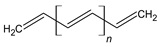 |
| Polypyrrole (PPy) | 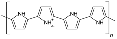 |
| Polythiophene (PTh) |  |
| Poly(3,4-ethylene dioxythiophene) (PEDOT) | 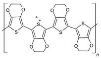 |
| Polyaniline (PANi) | 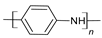 |
| Poly(para-phenylene) (PPP) |  |
| Poly(phenylene-vinylene) (PPV) | 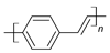 |
| Poly(thienylene-vinylene) (PTV) | 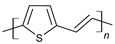 |
| Poly(furylene-vinylene) (PFV) |  |
| Poly(phenylene sulfide) (PPS) |  |
| Poly(phenylene-ethylene) (PPE) | 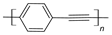 |
| Polyselenophene |  |
| Polyfuran |  |
| Polyindole |  |
| Polyfluorene |  |
| Polypyridine |  |
| Poly(diphenylamine) | 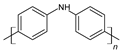 |
| Poly(thieno [3,2-b]pyrrole | 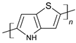 |
| Element | Binding Energy (eV) |
|---|---|
| Carbon (C1S) | 284.5–285.1 |
| Nitrogen (N1S) | 396.1–400.5 |
| Oxygen (O1s) | 526.2–533.5 |
| Silicon (Si2p) | 98.8–99.5 |
| Sulfur (S2p3/2) | 164.0–164.3 |
| Iron (Fe2p3/2) | 706.8–707.2 |
| Gold (Au4f7/2) | 83.8–84.2 |
Disclaimer/Publisher’s Note: The statements, opinions and data contained in all publications are solely those of the individual author(s) and contributor(s) and not of MDPI and/or the editor(s). MDPI and/or the editor(s) disclaim responsibility for any injury to people or property resulting from any ideas, methods, instructions or products referred to in the content. |
© 2024 by the authors. Licensee MDPI, Basel, Switzerland. This article is an open access article distributed under the terms and conditions of the Creative Commons Attribution (CC BY) license (https://creativecommons.org/licenses/by/4.0/).
Share and Cite
Roohi, Z.; Mighri, F.; Zhang, Z. Conductive Polymer-Based Electrodes and Supercapacitors: Materials, Electrolytes, and Characterizations. Materials 2024, 17, 4126. https://doi.org/10.3390/ma17164126
Roohi Z, Mighri F, Zhang Z. Conductive Polymer-Based Electrodes and Supercapacitors: Materials, Electrolytes, and Characterizations. Materials. 2024; 17(16):4126. https://doi.org/10.3390/ma17164126
Chicago/Turabian StyleRoohi, Zahra, Frej Mighri, and Ze Zhang. 2024. "Conductive Polymer-Based Electrodes and Supercapacitors: Materials, Electrolytes, and Characterizations" Materials 17, no. 16: 4126. https://doi.org/10.3390/ma17164126
APA StyleRoohi, Z., Mighri, F., & Zhang, Z. (2024). Conductive Polymer-Based Electrodes and Supercapacitors: Materials, Electrolytes, and Characterizations. Materials, 17(16), 4126. https://doi.org/10.3390/ma17164126