Article

Effect of Graphene on the Performance of Silicon–Carbon Composite Anode Materials for Lithium-Ion Batteries

1
Key Laboratory of Air-Driven Equipment Technology of Zhejiang Province, Quzhou University, Quzhou 324000, China
2
Guangxi Key Laboratory of Superhard Material, National Engineering Research Center for Special Mineral Material, Guangxi Technology Innovation Center for Special Mineral Material, China Nonferrous Metal (Guilin) Geology and Mining Co., Ltd., Guilin 541004, China
3
School of Materials Science and Engineering, Guangxi Key Laboratory of Information Materials, Guilin University of Electronic Technology, Guilin 541004, China
4
School of Environmental and Food Engineering, Liuzhou Vocational & Technical College, Liuzhou 545000, China
*
Authors to whom correspondence should be addressed.
Materials 2024, 17(3), 754; https://doi.org/10.3390/ma17030754
Submission received: 18 December 2023 / Revised: 30 January 2024 / Accepted: 2 February 2024 / Published: 4 February 2024
(This article belongs to the Section Electronic Materials)

Abstract

:
(Si/graphite)@C and (Si/graphite/graphene)@C were synthesized by coating asphalt-cracked carbon on the surface of a Si-based precursor by spray drying, followed by heat treatment at 1000 °C under vacuum for 2h. The impact of graphene on the performance of silicon–carbon composite-based anode materials for lithium-ion batteries (LIBs) was investigated. Transmission electron microscopy (TEM) and selected area electron diffraction (SAED) images of (Si/graphite/graphene)@C showed that the nano-Si and graphene particles were dispersed on the surface of graphite, and thermogravimetric analysis (TGA) curves indicated that the content of silicon in the (Si/graphite/graphene)@C was 18.91%. More bituminous cracking carbon formed on the surface of the (Si/graphite/graphene)@C due to the large specific surface area of graphene. (Si/Graphite/Graphene)@C delivered first discharge and charge capacities of 860.4 and 782.1 mAh/g, respectively, initial coulombic efficiency (ICE) of 90.9%, and capacity retention of 74.5% after 200 cycles. The addition of graphene effectively improved the cycling performance of the Si-based anode materials, which can be attributed to the reduction of electrochemical polarization due to the good structural stability and high conductivity of graphene.

1. Introduction

Recently, LIBs have attracted considerable attention as a promising power source for various applications, such as portable electronics and electric vehicles, due to their greater energy density, higher operating voltages, lower self-discharge, and maintenance requirements compared to other rechargeable batteries [1,2]. Graphite is a commercial anode material for LIBs, as it has a long cycle life, high coulombic efficiency, and quite a low cost [3,4]. However, its low specific lithiation capacity (372 mAh/g) is unable to meet the increasing demands of secondary batteries. Silicon (Si) anode material is one of the most promising alternatives for graphite, since its high theoretical capacity of 3579 mAh/g for Li15Si4 is about 10 times higher than that of graphite [5]. However, the disadvantages of the Si anode are low electrical conductivity and large volume changes on cycling, which leads to fast capacity fading and a poor cycle life [6,7,8]. Many studies have reported techniques for preparing silicon/carbon (Si/C) composites with different graphite or carbon precursors, which is an effective approach to suppress the severe capacity degradation of pure Si [9,10,11,12]. While Si is dispersed into the carbonaceous matrix, the Si/C composite can buffer the large volume expansion of Si and improve its conductivity [13,14,15,16]. Consequently, Si/C composites exhibit better reversible capacity and cycling performance. For example, silicon@carbon (Si@C) composites with an embedded structure were prepared by Chen et al. Silicon nanoparticles and carbon shells formed a stable solid electrolyte interface (SEI) film during the lithiation and delithiation processes at the working electrode. Si@C composites were successfully prepared by spray drying and subsequent calcination with a reversible capacity of 1033.70 mAh/g after 100 cycles at a current density of 1 A/g [17].
To address the low conductivity of Si, various studies report introducing conductive coating layers on the Si surface, which can effectively increase the conductivity of Si and improve overall electrochemical performance [18,19]. For instance, a composite material with a porous mesophase pitch double-layer carbon structure of coated silicon nanoparticles (Si@C@PMP) was fabricated by coating the Si nanoparticles with mesophase pitch-ordered soft carbon, which exhibit a reversible capacity of 774 mA h/g for 300 cycles at 0.2 A/g [20]. A Si-based composite with a double carbon layer (Si@C@C) coating was achieved using high-temperature pyrolysis and mechanical stirring, which significantly improved the electrochemical performance of the Si anode [21]. In our earlier research, a large-scale approach was designed to prepare a Si-based composite with a graphite@nano-Si coated with carbon pitch, and after 300 cycles, the graphite@nano-Si@C composite’s capacity retention was 66.03%. [21]. These approaches enhance the conductivity of the anode material by coating the silicon surface with an amorphous carbon layer.
Graphene is similar to the carbon matrix for nano-Si particles, which is important in the energy conversion field due to its superior electronic conductivity, excellent structural flexibility, and large specific surface area. When used as anode materials for lithium-ion batteries, graphene’s electrochemical energy storage performance is better than that of graphite, and its charging speed is faster than that of graphite, which is expected to achieve fast charging. In addition, high-current-discharge-capacity lithium-ion batteries will also be improved [2,22]. For anode materials, graphene has both the ability to provide good electron transport channels and excellent lithium-ion transport properties. However, graphene is difficult to compound directly with spherical nanosilicon, and silicon and graphene are usually dispersed on a graphite matrix [23,24]. Su et al. [25] prepared a Si/graphite@graphene by spray drying followed by heating treatment, and the sample exhibited a high initial charge capacity of 827 mAh/g at 100 mA/g. However, the capacity retention rate of the Si/graphite@graphene was only about 60% at 100 mA/g after 50 cycles, which still needs to be further improved for industrial requirements.
Herein, (Si/graphite)@C and (Si/graphite/graphene)@C were prepared by coating asphalt-cracked carbon on the nano-Si surface and a carbon precursor by spray drying followed by heat treatment at 1000 °C under vacuum for 2 h. The impact of graphene on the electrochemical performance and cycle stability of silicon–carbon composite-based anode materials for LIBs were investigated.

2. Experiment

2.1. Sample Preparation

Nano-Si was prepared in Tekna’s 15 kW induction plasma system using micron-sized Si powder (Shanghai Aladdin Biochemical Technology Co., Ltd., Fengxian District, Shanghai, China, specification or purity: 99.9%, 1–3 μm) as the raw material, with a previously reported preparation method [21]. Graphite powders (Fangda Carbon New Materials Co., Ltd., Lanzhou, China) exhibited a reversible capacity of 345 mAh/g. The preparation of (Si/graphite/graphene)@C was carried out as follows: nano-Si powder, graphene (Shanghai Aladdin Biochemical Technology Co., Ltd, Fengxian District, Shanghai, China; specification or purity: ink, 40%; solids: 100 g; viscosity: 5.5 Pa.s.), graphite, and methylcellulose (Shanghai Aladdin Biochemical Technology Co., Ltd., Fengxian District, Shanghai, China; specification or purity: 1500 mPa.s.), with a weight ratio of 20:5:73:2, were dispersed in deionized water by ultrasonication with mechanical stirring. Then, the uniformly dispersed liquid was spray-dried (Shanghai shunyi Tech Co., Ltd., Jiading District, Shanghai, China) to obtain a homogeneous precursor power. Next, the weight ratio of the precursor and asphalt powders (supplier: Hebei Hankai Energy Science and Technology Development Co., Ltd., Handan, China; CAS No. 8052-42-4; fineness: 0–3 mm, 80–100 mesh; fixed carbon: ≥40%) was set to 9:1, and the obtained mixture was added into a hot reactor and stirred for hot coating at 600 °C for 2 h and cooled to room temperature. Finally, the asphalt-coated precursor powers were taken into a vacuum furnace for heat treatment at 1000 °C under vacuum for 2 h to obtain the (Si/graphite/graphene)@C. The preparation of (Si/graphite)@C was similar to that mentioned above, with a nano-Si powder, graphite, and methylcellulose at a weight ratio of 20:78:2.

2.2. Sample Characterization

The crystalline phases of synthesized composites were characterized by X-ray diffraction (XRD; D8 ADVANCE; BrukerAXSGmbH, Baden-Württemberg, Germany) scanning in the range of 20° to 100°with scan rate 8°/min. Transmission electron microscopy (TEM; JEM-2100F; Nidec Corporation, Tokyo, Japan) and field emission electron microscopy (FE-SEM; Quanta 200; Thermo Fisher Scientific, Waltham, MA, USA) were used to study the composites’ microstructure and morphology. The content of Si in the synthesized material was verified by thermogravimetric analysis and differential scanning calorimetry (DSC).

2.3. Electrochemical Measurements

The 80 wt% (Si/graphite/graphene)@C and (Si/graphite)@C were used as the active materials, 10 wt% Super P (TIMCAL) as the conductive agent, and 10 wt% mixture solution of butadiene styrene rubber and carboxymethyl cellulose (Chengdu indigo power sources Co., Ltd., Chengdu, China, weight ratio 3:2) as the binder. The above three substances were added to the container, and deionized water was added and stirred to obtain 35 wt%. slurry. The slurry was coated onto Cu foil and dried for 8 h at 80 °C with vacuum tube test furnace to obtain test electrode.
The 2032 coin half-cell was assembled using the as-obtained 12 mm wafer electrode as the working electrode, with lithium metal foil as the counter electrode, Celgard 2400 as the separator, and 1 M LiPF6 in EC:EMC:DMC (1:1:1, v/v) as the electrolyte. At 100 mA/g to 0.01 V and then 10 mA/g to 0.005 V, discharge capacity was assessed. Charge capacity was assessed at 100 mA/g to 1.5 V, and cycle performance was repeatedly monitored. Electrochemical impedance spectroscopy (EIS) was carried out in the frequency range of 100 KHz to 0.01 Hz, using a Solartron 1287 electrochemical Workstation.

3. Results and Discussion

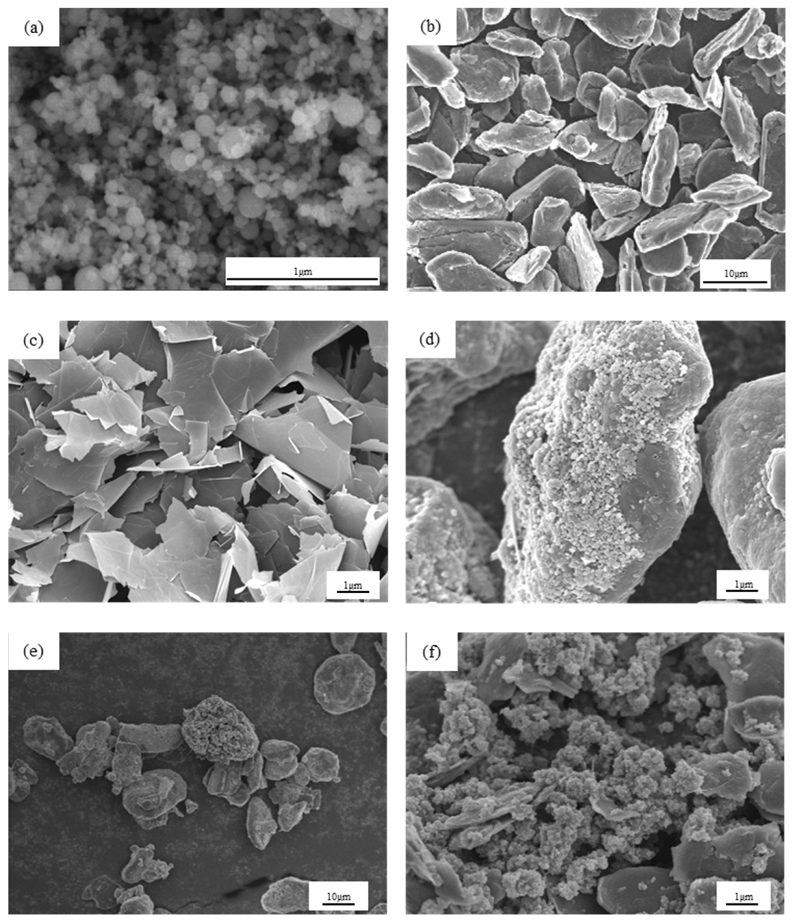
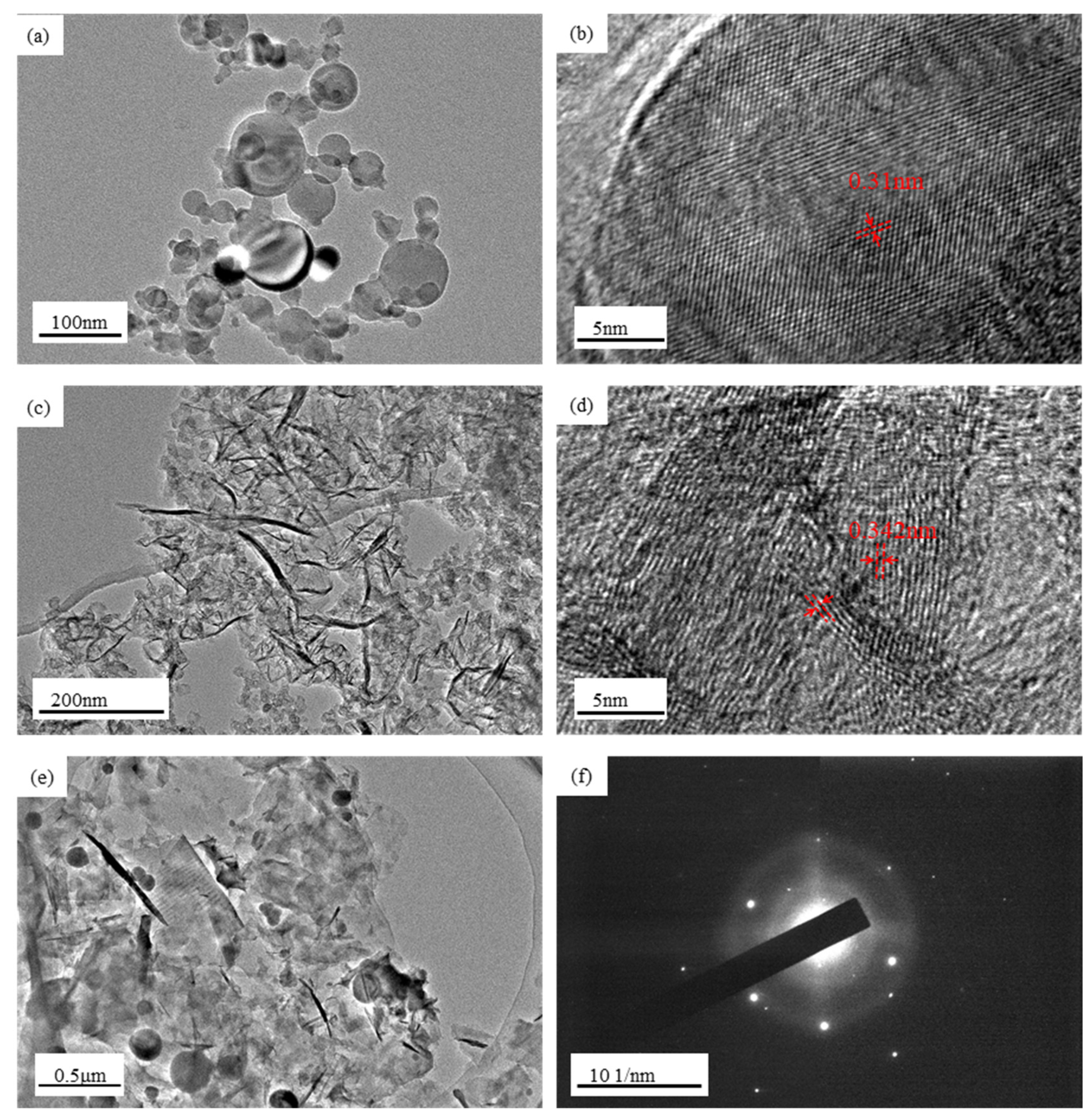
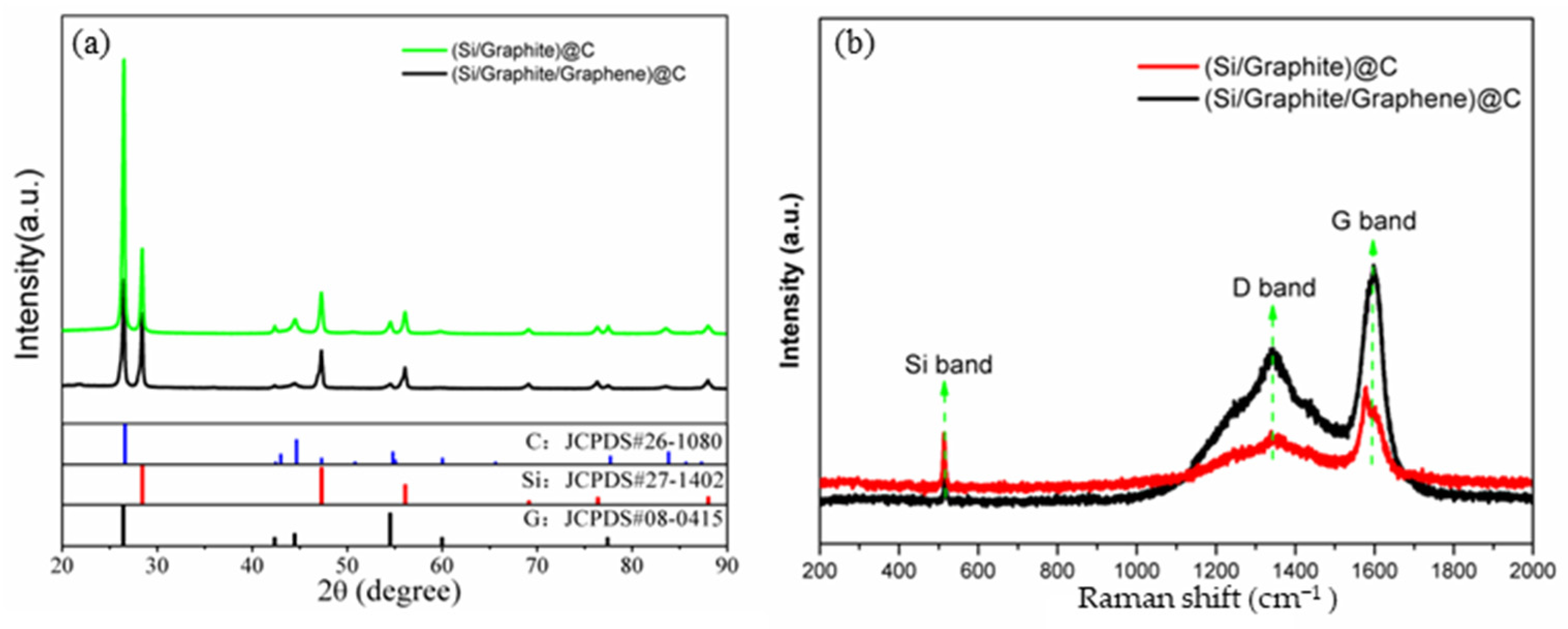
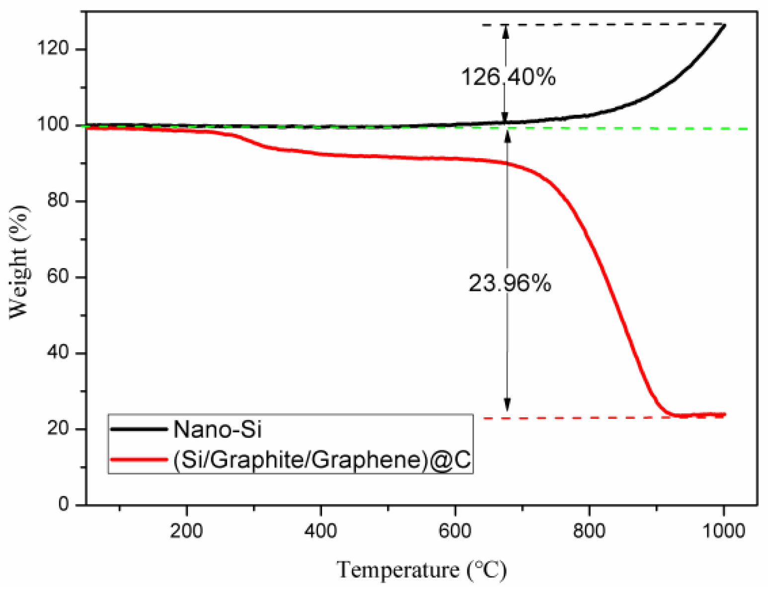
3.1. Materials Characterization

SEM images of (Si/graphite)@C and (Si/graphite/graphene)@C are shown in Figure 1. Figure 1a shows the morphology of silicon nanoparticles, which have a spherical structure with a nanometer diameter. Graphite has a lamellar structure with multiple particles stacked together with a particle size distribution between 5 and 20 µm and an average diameter of 8.46 µm, as shown in Figure 1b. Figure 1c shows the morphology of graphene, which has a lamellar structure. Figure 1d shows the morphology of (Si/graphite)@C with nano-Si particles distributed directly on the graphite particle surface. Nano-Si particles have a spherical morphology without obvious agglomeration and are randomly linked together due to surface tension and electrostatic forces. Figure 1e,f shows the morphology of (Si/graphite/graphene)@C, wherein nano-Si particles are mixed with graphene and are distributed on the surface of graphite particles, with some particles glued together under the action of bituminous cracking carbon, which contributes to the electrical conductivity of the material. Graphite particles are irregularly shaped with accidented surface, which is beneficial to loading nano-Si particles.
The TEM image of Si nanoparticles in Figure 2a,b shows spherical nanoparticles with varying sizes and single crystals of planar arrangement. In a single particle, the spacing between adjacent planes is about 0.31 nm, which corresponds to the (111) crystallographic plane of Si. Nanosized silicon particles can effectively alleviate the particle pulverization caused by the volume expansion of silicon and shorten the diffusion distance of lithium ions, thus improving the cycling stability performance of the electrode. However, volume expansion during charging and discharging leads to uneven distribution of stress at the interface of the composite material, resulting in poor cycling performance at high multiplicity. Graphene is distributed in a chain pattern with a polycrystalline arrangement, as shown in Figure 2c,d. TEM and SAED images of (Si/graphite/graphene)@C are shown in Figure 2e,f, respectively. The electron diffraction spot and electron diffraction ring in Figure 2f correspond to nanocrystalline Si and polycrystalline graphite structures, respectively. Graphene and nano-Si particles were well mixed, and the anode material’s electrical conductivity was increased due to the presence of graphene flakes, preventing the sample from making contact with the electrolyte. Moreover, the sufficient mixing of graphene and silicon nanoparticles alleviates the uneven stress distribution caused by the volume expansion of silicon and improves the cycling performance of the anode material at high multiplicity.
The structural characteristics of (Si/graphite)@C and (Si/graphite/graphene)@C were analyzed by XRD, as shown in Figure 3a. Carbon (JCPDS# 26-1080), crystalline graphite (JCPDS# 08-0415), and cubic Si (JCPDS# 27-1402) phases can be found in the main diffraction peaks [21]. The cubic Si phase corresponds to nano-Si; the carbon phase is mainly bituminous cracking carbon, while the crystalline graphitic phase is attributed to graphite and graphene. Moreover, there are no peaks of SiO2 or SiC in the XRD patterns, indicating that nano-Si is not oxidized or does not react with carbon during material preparation [26,27]. The Raman spectra in Figure 3b were further used to verify the structure of the composites. The sharp peak at 514 cm−1 is assigned to crystalline Si, while the peaks at 1347 cm−1 and 1596 cm−1 correspond to amorphous carbon (D band) and ordered structure graphitic carbon (G band), respectively [21,28,29]. The intensity of the D and G bands in (Si/graphite/graphene)@C are higher than those of (Si/graphite)@C, mainly due to the addition of graphene. The ordered structure of graphene results in the increase in the intensity of G band in (Si/graphite/graphene)@C. There is more bituminous cracking carbon formed on the surface of (Si/graphite/graphene)@C due to the large specific surface area of graphene; consequently, the intensity of the D band increases.
The Si content in (Si/graphite/graphene)@C was confirmed via the TGA curves of nano-Si and (Si/graphite/graphene)@C carried out in air. When heated to 1000 °C, Si was oxidized to SiO2, while graphite, graphene, and pitch carbon were oxidized to CO2 gas. Thus, the specific values of (Si/graphite/graphene)@C and nano-Si from the TGA curve (as shown in Figure 4) indicate silicon content in (Si/graphite/graphene)@C. The weight of nano-Si increased by 126.40%, while the weight of (Si/graphite/graphene)@C decreased by 23.96%. Thus, the Si content in (Si/graphite/graphene)@C could be calculated as 18.91% (23.96%/126.40%). The theoretical specific capacity of silicon is 3579 mAh/g. Multiplying the weight share of silicon by the theoretical specific capacity of silicon gives a maximum gram-specific capacity of 676.79 mAh/g (3579 × 18.91%) provided by silicon in (silicon/graphite/graphene)@C.

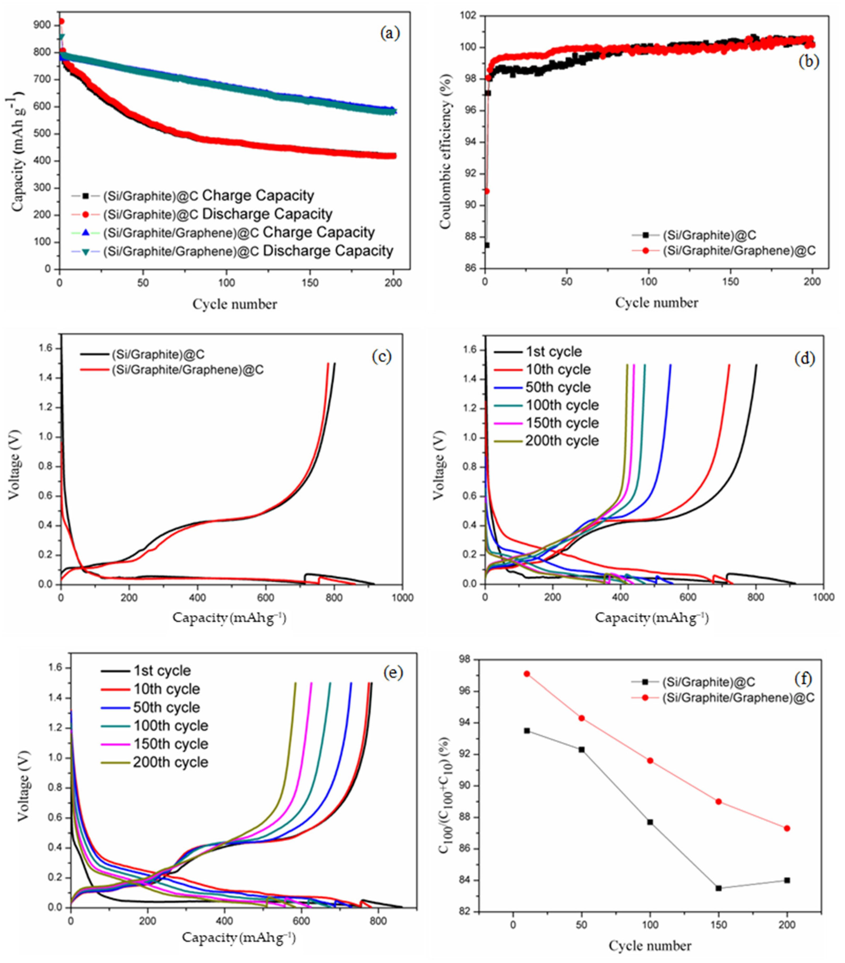
3.2. Electrochemical Properties

The cycling performance and coulombic efficiencies of the obtained composites were evaluated, as shown in Figure 5a,b, respectively. The first discharge and charge capacities of (Si/graphite/graphene)@C are 860.4 and 782.1 mAh/g, respectively. The ICE is 90.9%, and reversible charge capacity is 584.2 mAh/g for 200 cycles. Subtracting the gram-specific capacity provided by silicon from the first charge-specific capacity of the negative electrode material, it is calculated that the gram-specific capacity provided by the carbon material is at least 105.31 mAh/g (782.1–676.79). Assuming that the capacity of the carbon material does not decay after 200 cycles, subtracting the gram-specific capacity provided by the carbon material from the reversible charge-specific capacity of the negative electrode material after 200 cycles yields that the gram-specific capacity provided by silicon after 200 cycles is 478.89 mAh/g. After 200 cycles, comparing the specific capacity of silicon before and after the cycle, the final capacity retention rate of silicon in the anode material is 70.76% (478.89/676.79). Silicon in the anode material has good capacity retention. This shows that by adding carbon material, silicon can maintain good cycling performance.
On the other hand, the first discharge and charge capacities of (Si/graphite)@C are 915.9 and 801.3 mAh/g, respectively, with an ICE of 87.5% and reversible charge capacity of 419.6 mAh/g, after 200 cycles. The ICE of (Si/graphite)@C was lower than that of (Si/graphite/graphene)@C. The nano-Si particles in (Si/graphite)@C undergo volume expansion during discharging and volume shrinkage during charging. This typically results in the loss of electrical contact of the embedded lithium ions and the repeated formation of SEI films, which leads to lithium depletion and irreversible capacity loss. Graphene can prevent the loss of electrical contact during the discharge/charge process, thus improving the ICE of (Si/graphite/graphene)@C. Furthermore, the stability of the anode material structure is improved due to the excellent mechanical properties of graphene, thus leading to superior cycle properties and coulombic efficiency of (Si/graphite/graphene)@C. Consequently, the capacity retention ratio of (Si/graphite)@C increases from 52.4% to 74.5% after 200 cycles with the addition of graphene. The first discharge/charge curve in Figure 5c shows the discharge/charge voltage plateau for (Si/graphite/graphene)@C due to lithiation/delithiation of the active material. In Figure 5d,e, a comparative analysis of the discharge/charge curves of (Si/graphite)@C and (Si/graphite/graphene)@C shows that the voltage at the discharge/charge plateau reduced/increased from the 10th cycle to the 200th cycle after the 1st cycle activation. This is mainly due to worsening electrical contact and increasing thickness of the SEI film. Moreover, from the 1st cycle to the 50th cycle, the charge voltage plateau at 0.4 V in (Si/graphite)@C shows a sharp decrease. This indicates that the capacity contribution of the nano-Si particles is decreased due to the loss of electrical contact of the nano-Si particles during the charge/discharge process, with an irreversible change in volume. The cycling performance of the samples was studied by first discharging to 0.01 V at 100 mA/g and then discharging to 0.005 V at 10 mA/g. The capacity ratio variation of discharge capacity at 100 mA/g and total discharge capacity can be used to evaluate discharge ability at high current. As shown in Figure 5f, the capacity ratios of (Si/graphite/graphene)@C and (Si/graphite)@C are 87.2% and 84.1%, respectively, after 200 cycles, and the capacity decrease rate of (Si/graphite/graphene)@C is slower than that of (Si/graphite)@C with an increase in the number of cycles, which suggests that the high current discharge ability and high rate-cycling stability of the former composite are higher than those of (Si/graphite)@C. The incorporation of graphene reduces electrochemical polarization, which improves high current discharge capability. Moreover, the sufficient mixing of graphene and silicon nanoparticles alleviates the uneven stress distribution caused by the volume expansion of silicon and improves the cycling performance of the anode material at high multiplicity.
Table 1 shows the electrochemical properties and material structures of several of our earlier-prepared silicon–carbon composite anode materials for lithium batteries. Compared to previous silicon–graphite anode materials, the addition of graphene resulted in a significant increase in the first coulomb efficiency of the materials. However, the excessive specific surface area of the carbon-based material is not favorable for the increase of the first coulomb efficiency [30]. This may be due to the fact that uniform mixing of graphene and nanosilicon affects the formation of the amorphous carbon layer, which makes the amorphous carbon layer smooth and leads to a decrease in the specific surface area of the composite material, which in turn reduces the formation of the SEI film and improves the first coulombic efficiency of the anode material.

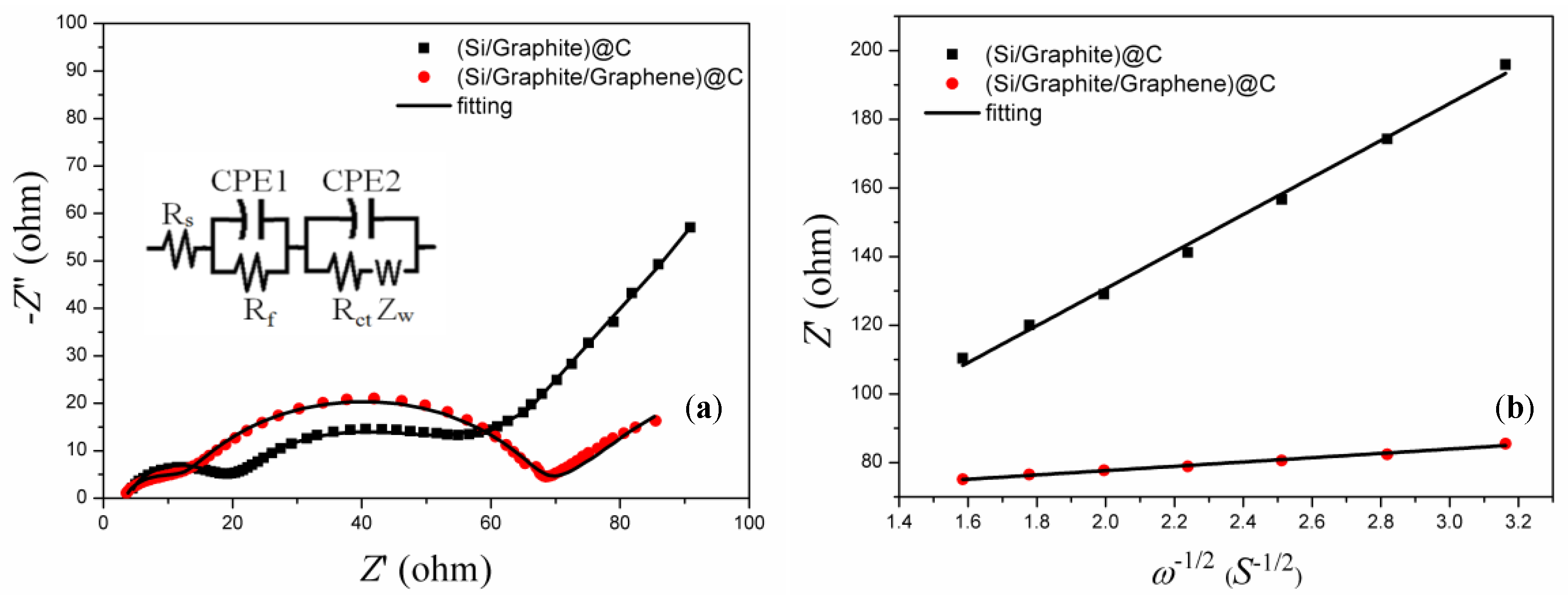
3.3. Electrochemical Kinetic Properties

The electrochemical impedance curves of the (Si/graphite)@C and (Si/graphite/graphene)@C electrodes after 10 cycles, in a fully charged state, were fitted by an equivalent circuit shown in the right corner in Figure 6a to study the electrode structure change and electrochemical kinetics of the samples, and the results are listed in Table 2. Contact resistance Rs (including solution resistance between the working and reference electrodes)of the (Si/graphite/graphene)@C electrode is 3.39 Ω, which is lower than that of the (Si/graphite)@C electrode, indicating that the addition of graphene enhanced particle contact and improved electrical conductivity, leading to low contact resistance [33]. Rf reveals the forming condition of the SEI films. Since graphene has excellent mechanical properties, it promotes a stable SEI film [33,34]; thus, the Rf value of the (Si/graphite/graphene)@C electrode is 8.52 Ω, which is lower than that of the (Si/graphite)@C electrode. Furthermore, in (Si/graphite/graphene)@C, graphene can inhibit particle pulverization, preventing an increase in the charge transfer surface; thus, the charge transfer resistance, Rct, of (Si/graphite/graphene)@C is higher than that of the (Si/graphite)@C [21,28].
The presence of a straight line in electrochemical impedance spectra typically reveals lithium-ion diffusion kinetics [35,36]. The effective lithium-ion diffusion coefficient can be evaluated by the following equation [37,38]:
D = R 2 T 2 2 A 2 n 4 F 4 C 2 σ 2  
C = n V = m / M V = ρ V / M V = ρ M  
where R is the gas constant; F is the Faraday constant; n is the number of electrons in the electron transfer reaction and has a value of 1; T is 298 K; C is the lithium-ion concentration, which can be calculated from the densities and molecular weights of materials synthesized by different methods, with a value of 3.19 × 10⁴ mol m−3, and the derivation process is shown in Equation (2); and σ is the slope of the straight line Z′~ω−1/2 as shown in Figure 6b. The lithium-ion diffusion coefficient of the (Si/graphite/graphene)@C electrode is 6.86 × 10⁻¹³ cm2 s−1, which is about 70 times that of the (Si/graphite)@C electrode, mainly because graphene improved lithium-ion transport properties and lowered the thickness of the SEI film, which is also beneficial to lithium-ion diffusion. The high lithium-ion diffusion coefficient is in good agreement with the good cyclability and reversible charge capacity of the (Si/graphite/graphene)@C composite.

4. Conclusions

The (Si/graphite/graphene)@C obtained by adding graphene to the Si/C composite anode material showed excellent electrochemical properties. First discharge/charge capacities of 860.4 and 782.1 mAh/g were obtained, with an ICE of 90.9% and a capacity retention of 74.5% after 200 cycles. The cycling and rate performance of the (Si/graphite/graphene)@C anode material improved effectively compared with (Si/graphite)@C. The incorporation of graphene into the Si/C composite reduced contact resistance, inhibited the fragmentation of the active material particles, and reduced the formation of SEI films. Graphene led to improved lithium-ion diffusion and excellent mechanical properties during charging. This study demonstrated that the proposed (Si/graphite/graphene)@C is a promising anode material for LIBs with high energy density requirements.

Author Contributions

Conceptualization, C.N., C.X. and W.L.; methodology, C.N.; validation, C.N., Z.S., X.L. and H.Q.; formal analysis, C.N., C.X. and W.L.; investigation, C.N., W.X. and Z.T.; data curation, W.X., Z.T., Z.S., X.L. and H.Q.; writing—original draft preparation, C.N., W.L. and W.X.; writing—review and editing, C.N. and C.X.; funding acquisition, C.X. and W.L. All authors have read and agreed to the published version of the manuscript.

Funding

This work was supported by the Guangxi Science and Technology Project (ZY21195037), the Scientific and Technological Plan of Guilin City (20210207-4), the Scientific and Technological Plan of Liuzhou City (2022CCC0201), the Quzhou Science and Technology Bureau (Grant No.2021K26), and the Joint Funds of the Zhejiang Provincial Natural Science Foundation of China (Grant No. LZY22E010002, LZY23E010001).

Institutional Review Board Statement

Not applicable.

Informed Consent Statement

Not applicable.

Data Availability Statement

Data are contained within the article.

Conflicts of Interest

Authors Wenping Liu, Xiaoxu Lei and Haiqing Qin were employed by the company China Nonferrous Metal (Guilin) Geology and Mining Co., Ltd. The remaining authors declare that the research was conducted in the absence of any commercial or financial relationships that could be construed as a potential conflict of interest.

References

  1. Sanguesa, J.A.; Torres-Sanz, V.; Garrido, P.; Martinez, F.J.; Marquez-Barja, J.M. A Review on Electric Vehicles: Technologies and Challenges. Smart Cities 2021, 4, 372–404. [Google Scholar] [CrossRef]
  2. Tan, S.; Shadike, Z.; Cai, X.Y.; Lin, R.Q.; Kludze, A.; Borodin, O.; Lucht, B.L.; Wang, C.S.; Hu, E.Y.; Xu, K.; et al. Review on Low-Temperature Electrolytes for Lithium-Ion and Lithium Metal Batteries. Electrochem. Energy Rev. 2023, 6, 35. [Google Scholar] [CrossRef]
  3. Asenbauer, J.; Eisenmann, T.; Kuenzel, M.; Kazzazi, A.; Chen, Z.; Bresser, D. The success story of graphite as a lithium-ion anode material-fundamentals, remaining challenges, and recent developments including silicon (oxide) composites. Sustain. Energy Fuels 2020, 4, 5387–5416. [Google Scholar] [CrossRef]
  4. Tian, H.H.; Graczyk-Zajac, M.; Kessler, A.; Weidenkaff, A.; Riedel, R. Recycling and Reusing of Graphite from Retired Lithium-ion Batteries: A Review. Adv. Mater. 2023, 35, e2308494. [Google Scholar] [CrossRef] [PubMed]
  5. Zhao, X.Y.; Lehto, V.P. Challenges and prospects of nanosized silicon anodes in lithium-ion batteries. Nanotechnology 2021, 32, 042002. [Google Scholar] [CrossRef] [PubMed]
  6. Pendashteh, A.; Tomey, R.; Vilatela, J.J. Nanotextile 100% Si Anodes for the Next Generation Energy-Dense Li-ion Batteries. Adv. Energy Mater. 2024, 14, 2304018. [Google Scholar] [CrossRef]
  7. Koebbing, L.; Latz, A.; Horstmann, B. Voltage Hysteresis of Silicon Nanoparticles: Chemo-Mechanical Particle-SEI Model. Adv. Funct. Mater. 2023, 33, 2308818. [Google Scholar] [CrossRef]
  8. Sztymela, K.; Rossignol, F.; Bienia, M.; Zapp, N.; Nikolowski, K.; Cerbelaud, M. Fabrication of 3D silicon anode by inkjet printing: Opportunities and challenges. J. Energy Storage 2024, 75, 109567. [Google Scholar] [CrossRef]
  9. Idrees, M.; Batool, S.; Kong, J.; Zhuang, Q.; Liu, H.; Shao, Q.; Lu, N.; Feng, Y.N.; Wujcik, E.K.; Gao, Q.; et al. Polyborosilazane derived ceramics-Nitrogen sulfur dual doped graphene nanocomposite anode for enhanced lithium ion batteries. Electrochim. Acta 2019, 296, 925–937. [Google Scholar] [CrossRef]
  10. Maddipatla, R.; Loka, C.; Lee, K.S. Exploring the Potential of Carbonized Nano-Si within G@C@Si Anodes for Lithium-Ion Rechargeable Batteries. ACS Appl. Mater. Interfaces 2023, 15, 58437–58450. [Google Scholar] [CrossRef]
  11. Araño, K.G.; Yang, G.; Armstrong, B.L.; Aytug, T.; Chambers, M.S.; Self, E.C.; Meyer, H.M., III; Quinn, J.; Browning, J.F.; Wang, C.M.; et al. Carbon Coating Influence on the Formation of Percolating Electrode Networks for Silicon Anodes. Acs Appl. Energy Mater. 2023, 6, 11308–11321. [Google Scholar] [CrossRef]
  12. Kim, J.H.; Song, A.R.; Park, J.M.; Park, J.S.; Behera, S.; Cho, E.M.; Park, Y.C.; Kim, N.Y.; Jung, J.W.; Lee, S.J.; et al. Analogous Design of a Microlayered Silicon Oxide-Based Electrode to the General Electrode Structure for Thin-Film Lithium-Ion Batteries. Adv. Mater. 2024, 36, 2309183. [Google Scholar] [CrossRef] [PubMed]
  13. Bitew, Z.; Tesemma, M.; Beyene, Y.; Amare, M. Nano-structured silicon and silicon based composites as anode materials for lithium ion batteries: Recent progress and perspectives. Sustain. Energy Fuels 2022, 6, 1014–1050. [Google Scholar] [CrossRef]
  14. Schulze, M.C.; Fink, K.; Palmer, J.; Carroll, G.M.; Dutta, N.S.; Zwiefel, C.; Engtrakul, C.; Han, S.D.; Neale, N.R.; de Villers, B.T. Pitch Carbon-coated Ultrasmall Si Nanoparticle Lithium-ion Battery Anodes Exhibiting Reduced Reactivity with Carbonate-based Electrolyte. Batter. Supercaps 2023, 6, e202300186. [Google Scholar] [CrossRef]
  15. Church, R.B.; Gao, H.N.; Gallant, B.M.; Hart, A.J. Thick Architected Silicon Composite Battery Electrodes Using Honeycomb Patterned Carbon Nanotube Forests. J. Electrochem. Soc. 2023, 170, 090543. [Google Scholar] [CrossRef]
  16. Vila, M.N.; Bernardez, E.M.; Li, W.Z.; Stackhouse, C.A.; Kern, C.J.; Head, A.R.; Tong, X.; Yan, S.; Wang, L.; Bock, D.C.; et al. Interfacial Reactivity of Silicon Electrodes: Impact of Electrolyte Solvent and Presence of Conductive Carbon. Acs Appl. Mater. Interfaces 2022, 14, 20404–20417. [Google Scholar] [CrossRef] [PubMed]
  17. Chen, H.D.; Hou, X.H.; Qu, L.N.; Qin, H.Q.; Ru, Q.; Huang, Y.; Hu, S.J.; Lam, K.H. Electrochemical properties of core-shell nano-Si@carbon composites as superior anode materials for high-performance Li-ion batteries. J. Mater. Sci.-Mater. Electron. 2017, 28, 250–258. [Google Scholar] [CrossRef]
  18. Hamid, F.H.; Karunawan, J.; Irmawati, Y.; Laksono, B.T.; Peiner, E.; Wasisto, H.S.; Iskandar, F.; Sumboja, A. Cationic surfactant assisted electrostatic self-assembly of nitrogen-rich carbon enwrapped silicon anode: Unlocking high lithium storage performance. Electrochim. Acta 2023, 471, 143384. [Google Scholar] [CrossRef]
  19. Lim, G.H.; Song, D.Y.; O, M.J.; Kang, Y.C.; Lee, J.W.; Roh, K.C. Utilizing Hydrolysate Derived from Biorefinery as a Carbon Coating Source for Silicon-Carbon Anodes in Lithium-Ion Capacitors. Acs Appl. Energy Mater. 2023, 6, 11100–11107. [Google Scholar] [CrossRef]
  20. Wang, W.C.; Du, J.T.; Xu, Z.P.; Liu, Z.T.; Jia, H.A.; Li, T.J.; Nie, Y.; Song, K.D. Porous dual carbon framework coated silicon nanoparticles for high-performance lithium-ion batteries. J. Mater. Sci.-Mater. Electron. 2023, 34, 809. [Google Scholar] [CrossRef]
  21. Liu, W.P.; Xu, H.R.; Qin, H.Q.; Lv, Y.L.; Wang, F.; Zhu, G.S.; Lin, F.; Wang, L.H.; Ni, C.Y. The effect of carbon coating on graphite@nano-Si composite as anode materials for Li-ion batteries. J. Solid State Electrochem. 2019, 23, 3363–3372. [Google Scholar] [CrossRef]
  22. Kothandam, G.; Singh, G.; Guan, X.W.; Lee, J.M.; Ramadass, K.; Joseph, S.; Benzigar, M.; Karakoti, A.; Yi, J.B.; Kumar, P.; et al. Recent Advances in Carbon-Based Electrodes for Energy Storage and Conversion. Adv. Sci. 2023, 10, e2301045. [Google Scholar] [CrossRef] [PubMed]
  23. Ku, M.; Park, D.; Kim, M.; Choi, M.; Choi, W. Hydrophobic dispersion-derived Si/rGO nanocomposites in SiOC ceramic matrix as anode materials for high performance lithium-ion batteries. J. Mater. Chem. A 2023, 11, 15277–15285. [Google Scholar] [CrossRef]
  24. Kim, Y.H.; Choi, S.G.; Chung, K.Y.; Lee, G.W.; Choi, Y.G.; Kim, K.B. Roll-Pressed Silicon Anodes with High Reversible Volumetric Capacity Achieved by Interfacial Stabilization and Mechanical Strengthening of a Silicon/Graphene Hybrid Assembly. Small 2023, 19, e2301744. [Google Scholar] [CrossRef] [PubMed]
  25. Su, M.R.; Wang, Z.X.; Guo, H.J.; Li, X.H.; Huang, S.L.; Xiao, W.; Gan, L. Enhancement of the Cyclability of a Si/Graphite@Graphene composite as anode for Lithium-ion batteries. Electrochim. Acta 2014, 116, 230–236. [Google Scholar] [CrossRef]
  26. Zhou, Y.; Tian, Z.Y.; Fan, R.J.; Zhao, S.R.; Zhou, R.; Guo, H.J.; Wang, Z.X. Scalable synthesis of Si/SiO2@C composite from micro-silica particles for high performance lithium battery anodes. Powder Technol. 2015, 284, 365–370. [Google Scholar] [CrossRef]
  27. Zhou, Y.; Guo, H.J.; Wang, Z.X.; Li, X.H.; Zhou, R.; Peng, W.J. Improved electrochemical performance of Si/C material based on the interface stability. J. Alloys Compd. 2017, 725, 1304–1312. [Google Scholar] [CrossRef]
  28. Naveenkumar, P.; Maniyazagan, M.; Yang, H.W.; Kang, W.S.; Kim, S.J. Nitrogen-doped graphene/silicon-oxycarbide nanosphere as composite anode for high-performance lithium-ion batteries. J. Energy Storage 2023, 59, 106572. [Google Scholar] [CrossRef]
  29. Tseng, W.S.; Chen, Y.C.; Hsu, C.C.; Lu, C.H.; Wu, C.I.; Yeh, N.C. Direct large-area growth of graphene on silicon for potential ultra-low-friction applications and silicon-based technologies. Nanotechnology 2020, 31, 335602. [Google Scholar] [CrossRef]
  30. Chen, H.D.; Shen, K.X.; Hou, X.H.; Zhang, G.Z.; Wang, S.F.; Chen, F.M.; Fu, L.J.; Qin, H.Q.; Xia, Y.C.; Zhou, G.F. Si-based anode with hierarchical protective function and hollow ring-like carbon matrix for high performance lithium ion batteries. Appl. Surf. Sci. 2019, 470, 496–506. [Google Scholar] [CrossRef]
  31. Ni, C.Y.; Xia, C.D.; Liu, W.P.; Shan, Z.Q.; Lei, X.X.; Qin, H.Q.; Xu, W. Effect of combination methods for nanosilicon and graphite composites on the anode performance of lithium batteries. J. Mater. Sci.-Mater. Electron. 2023, 34, 1432. [Google Scholar] [CrossRef]
  32. Xu, W.; Ni, C.Y.; Xia, C.D.; Piao, Z.Y.; Liu, W.P. Effect of silicon/carbon composite on properties of Graphite anode materials in Li-ion batteries. Int. J. Electrochem. Sci. 2022, 17, 221117. [Google Scholar] [CrossRef]
  33. Kasper, M.; Moertelmaier, M.; Ragulskis, M.; R-Smith, N.A.; Angerer, J.; Aufreiter, M.; Romero, A.; Krummacher, J.; Xu, J.J.; Root, D.E.; et al. Calibrated Electrochemical Impedance Spectroscopy and Time-Domain Measurements of a 7 kWh Automotive Lithium-Ion Battery Module with 396 Cylindrical Cells. Batter. Supercaps 2023, 6, e202200415. [Google Scholar] [CrossRef]
  34. Adenusi, H.; Chass, G.A.; Passerini, S.; Tian, K.V.; Chen, G.H. Lithium Batteries and the Solid Electrolyte Interphase (SEI)-Progress and Outlook. Adv. Energy Mater. 2023, 13, 2203307. [Google Scholar] [CrossRef]
  35. Morris, L.V.; Ortíz-Ledón, C.A.; Hamers, R.J. Adapting Simultaneous in Operando Electrochemical Quartz Crystal Microbalance and Electrochemical Impedance Spectroscopy to Studies of Solid Electrolyte Interface Layer Formation on Amorphous Silicon Anodes. J. Electrochem. Soc. 2023, 170, 050503. [Google Scholar] [CrossRef]
  36. Yesilbas, G.; Chou, C.Y.; Bandarenka, A.S. A Physical Impedance Model of Lithium Intercalation into Graphite Electrodes for a Coin-Cell Assembly. Chemelectrochem 2023, 10, e202300270. [Google Scholar] [CrossRef]
  37. Yang, C.F.; Zhang, X.S.; Huang, M.Y.; Huang, J.J.; Fang, Z.B. Preparation and Rate Capability of Carbon Coated LiNi1/3Co1/3Mn1/3O2 as Cathode Material in Lithium Ion Batteries. ACS Appl. Mater. Interfaces 2017, 9, 12408–12415. [Google Scholar] [CrossRef]
  38. Wang, X.Y.; Hao, H.; Liu, J.L.; Huang, T.; Yu, A.S. A novel method for preparation of macroposous lithium nickel manganese oxygen as cathode material for lithium ion batteries. Electrochim. Acta 2011, 56, 4065–4069. [Google Scholar] [CrossRef]
Figure 1. SEM images of (a) nano-Si, (b) graphite, (c) graphene, (d) (Si/graphite)@C composite, and (e,f) (Si/graphite/graphene)@C composite.
Materials 17 00754 g001
Figure 2. TEM images of (a,b) nano-Si, (c,d) graphene, and (e) (Si/graphite/graphene)@C composite; (f) SAED image of (Si/graphite/graphene)@C composite.
Materials 17 00754 g002
Figure 3. (a) XRD pattern and (b) Raman spectra of (Si/graphite)@C and (Si/graphite/graphene)@C composite.
Materials 17 00754 g003
Figure 4. TGA curves of nano-Si and (Si/graphite/graphene)@C composite.
Materials 17 00754 g004
Figure 5. (a) Cycling performance, (b) first charge/discharge curves, and (c) first charge/discharge curves of (Si/graphite)@C and (Si/graphite/graphene)@C composite; discharge/charge curves of (d) (Si/graphite)@C composite and (e) (Si/graphite/graphene)@C composite; (f) capacity ratio variation curves of discharge current at 100 mA/g with different cycles.
Materials 17 00754 g005
Figure 6. (a) Nyquist plots of graphite, Si/G composite, and (Si/G)@C composite after 10 cycles; (b) relationship between Z′ and ω−1/2 in low-frequency region derived from Figure 6a.
Materials 17 00754 g006
Table 1. Electrochemical performance and material structure of our earlier-prepared silicon–carbon composite anode materials for lithium batteries.
Material StructureFirst Discharge CapacityInitial Columbic EfficiencyReference
Graphite-loaded carbon-coated nanosilicon and carbon-coated graphite460 mAh/g89.8%[31]
Si/G composites (graphite mixed with silicon nanoparticles)703.8 mAh/g84.95%[32]
(Si/G)@C composites (graphite mixed with silicon nanoparticles and coated with sucrose-cracked carbon)644.3 mAh/g88.93%[32]
(Si/graphite/graphene)@C860.4 mAh/g90.9%This work
(Si/graphite)@C915.9 mAh/g87.5%This work
Table 2. Kinetic parameters of electrodes after 10 cycling.
SamplesRs (Ω)Rf (Ω)Rct (Ω)SlopeDLi+ (cm2 s−1)
(Si/graphite)@C4.1313.8730.9653.949.36 × 10−15
(Si/graphite/graphene)@C3.398.5255.746.306.86 × 10−13
Disclaimer/Publisher’s Note: The statements, opinions and data contained in all publications are solely those of the individual author(s) and contributor(s) and not of MDPI and/or the editor(s). MDPI and/or the editor(s) disclaim responsibility for any injury to people or property resulting from any ideas, methods, instructions or products referred to in the content.

