
Vibration Fatigue Analysis of Two Different Variants of Oil Suction Pipes

 , , , and
Abstract
:1. Introduction
2. Materials and Methods
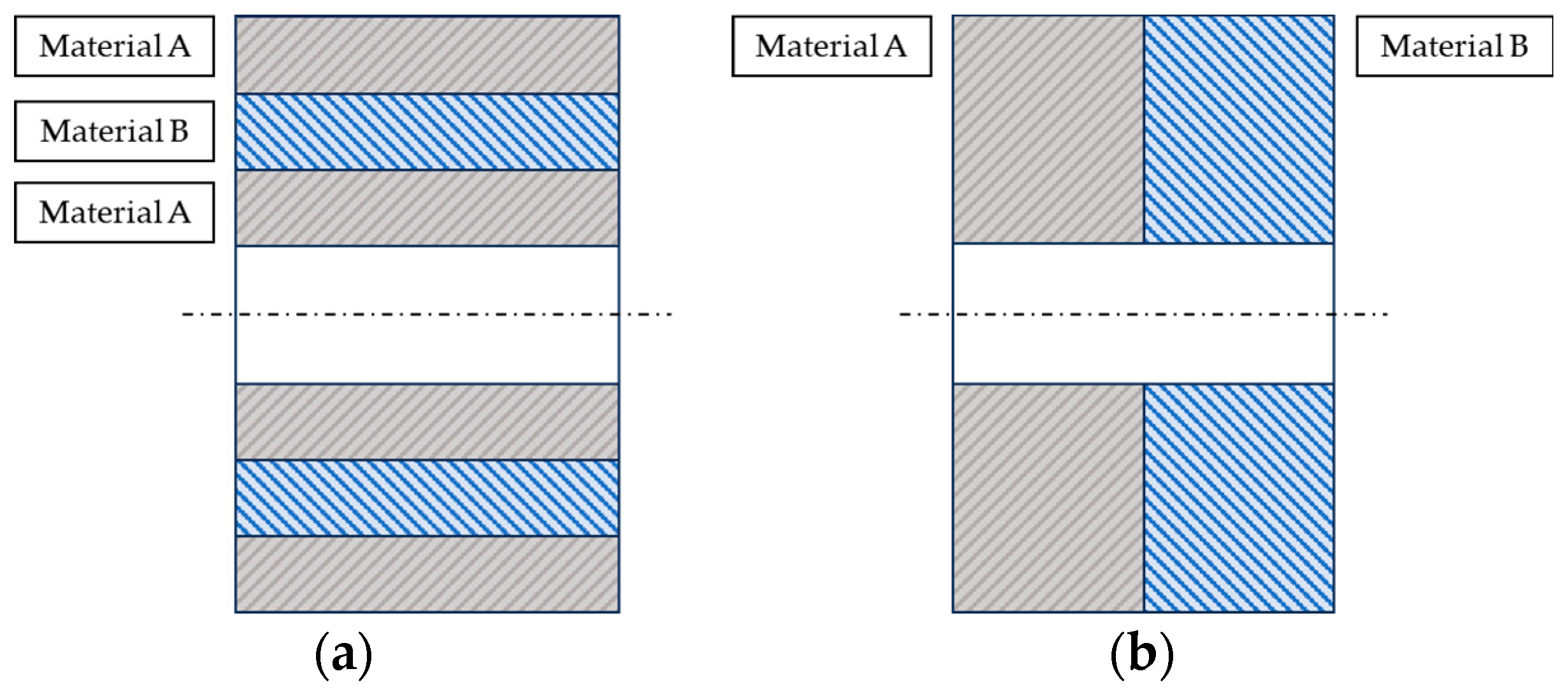
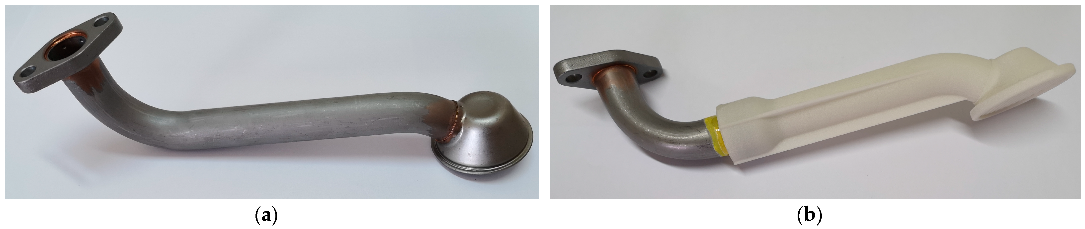
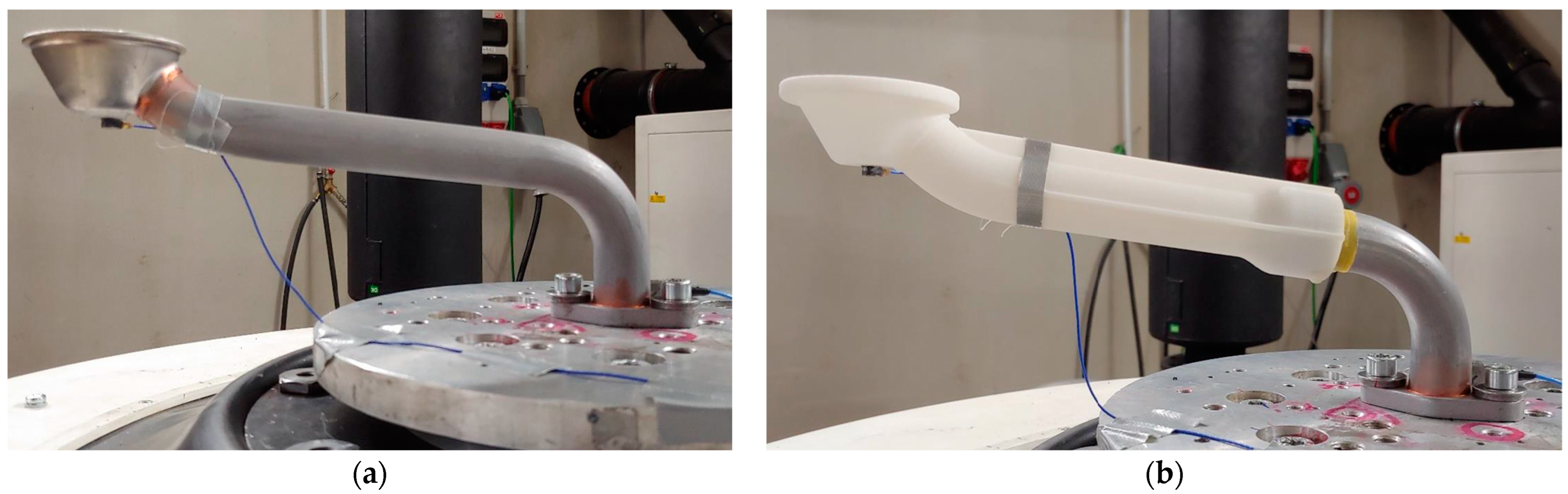
2.1. Materials and the Oil Suction Pipe Design
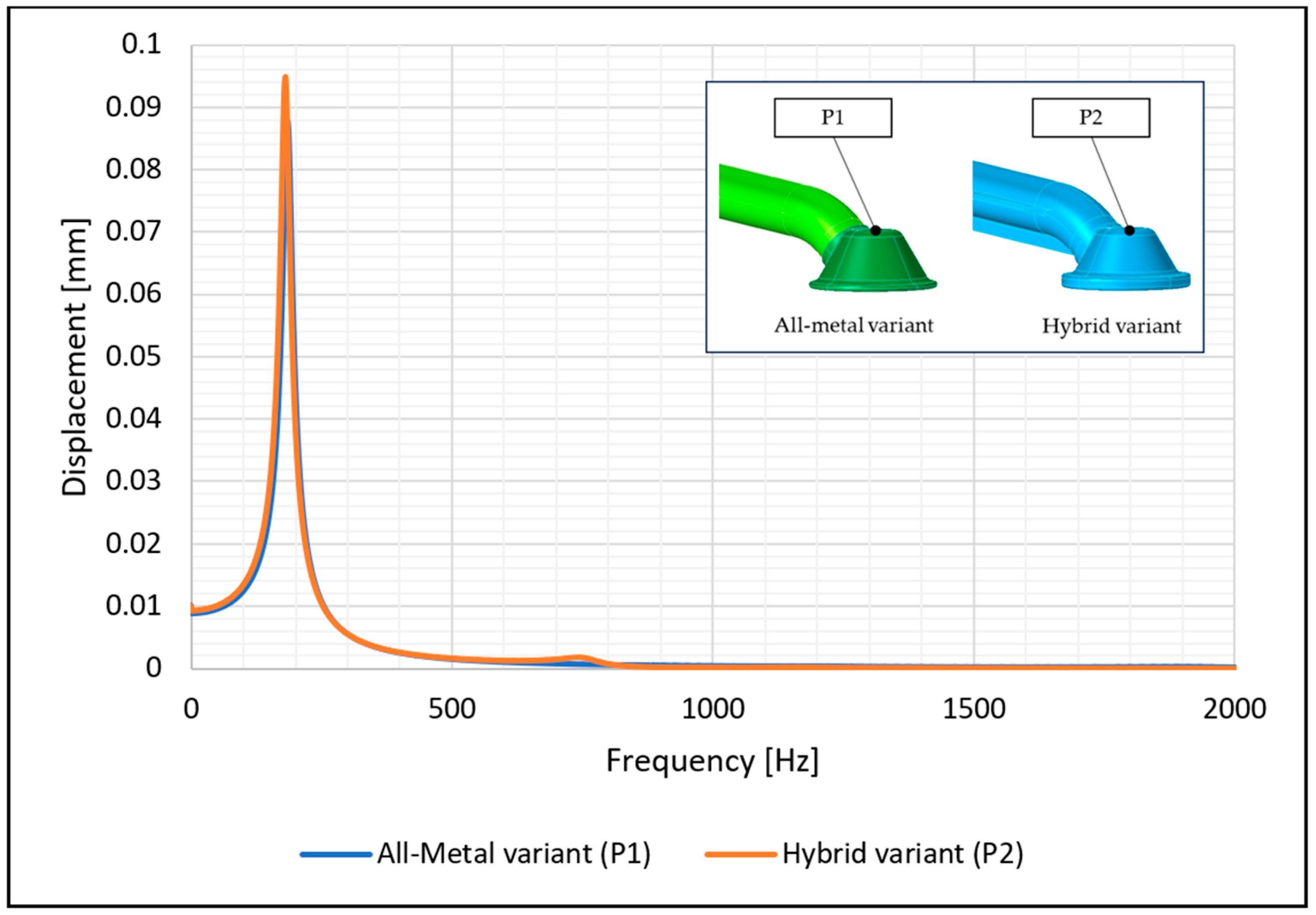
2.2. Random Vibration Analysis of the Intake Pipes
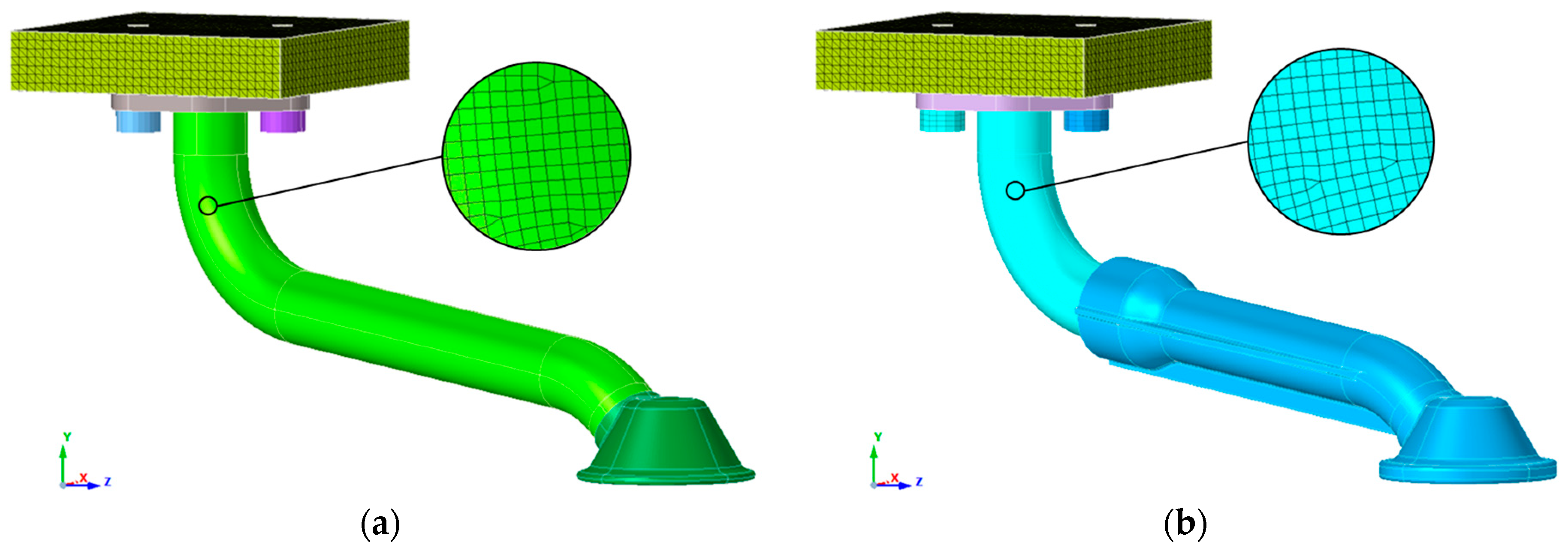
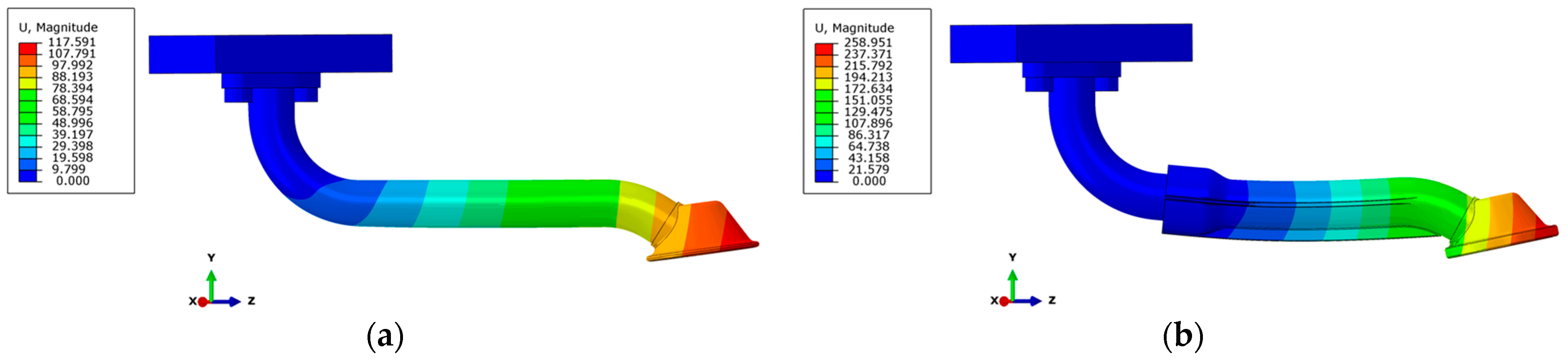
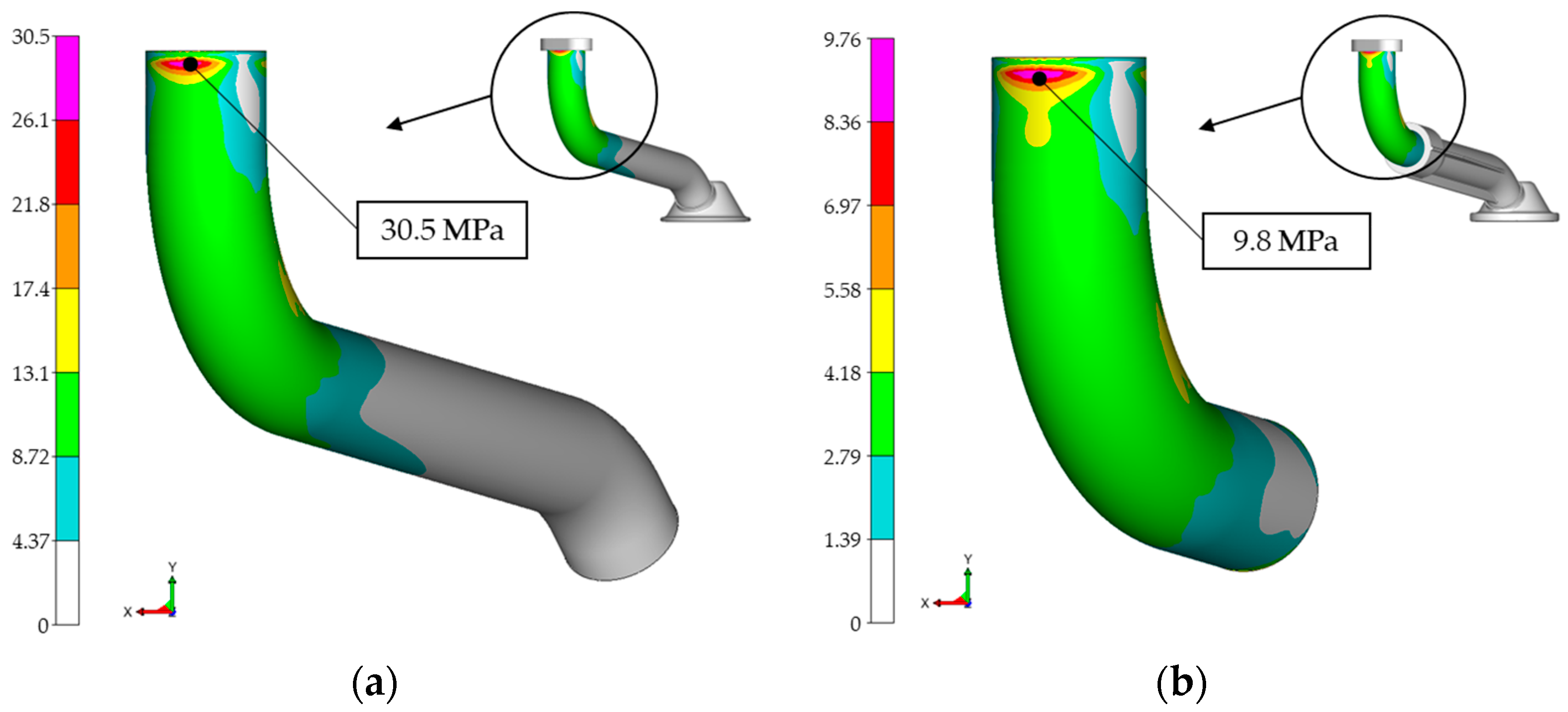
2.3. Numerical Simulation
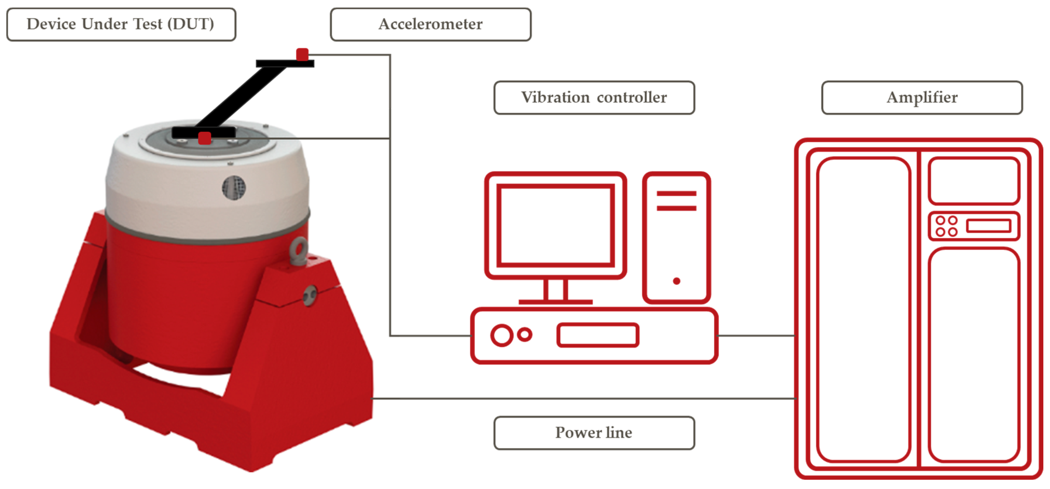
2.4. Experimental Analysis
3. Results and Discussion
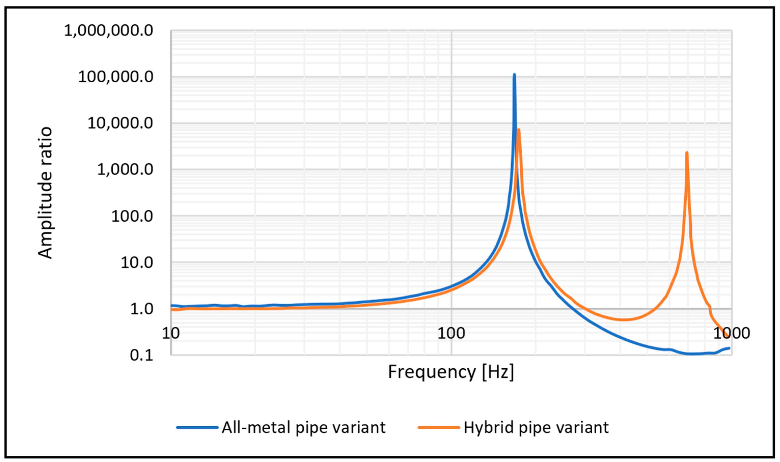
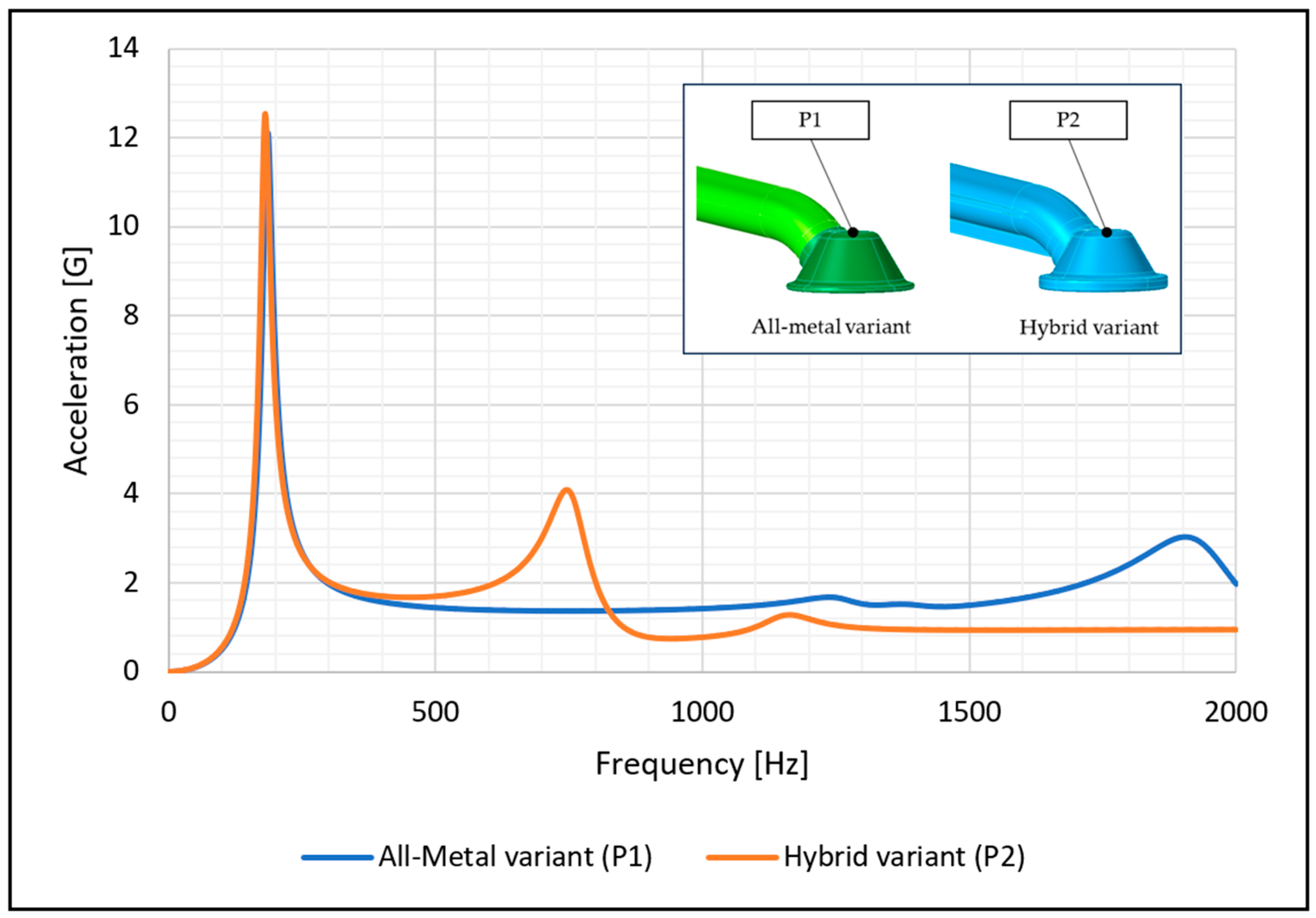
3.1. Modal Analysis
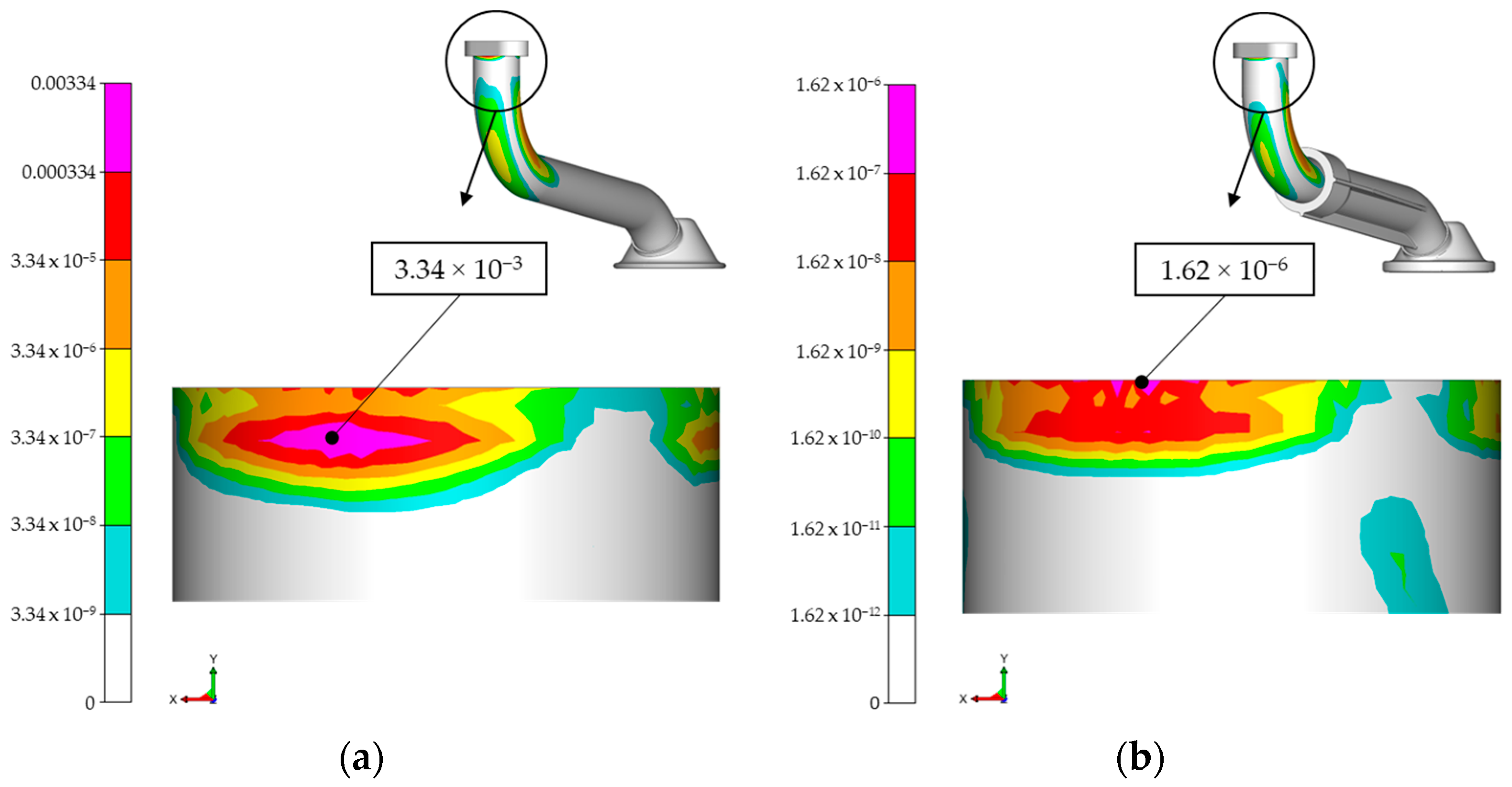
3.2. Fatigue Life
4. Conclusions
Author Contributions
Funding
Institutional Review Board Statement
Informed Consent Statement
Data Availability Statement
Conflicts of Interest
References
- Czerwinski, F. Current Trends in Automotive Lightweighting Strategies and Materials. Materials 2021, 14, 6631. [Google Scholar] [CrossRef] [PubMed]
- Wenlong, S.; Xiaokai, C.; Lu, W. Analysis of Energy Saving and Emission Reduction of Vehicles Using Light Weight Materials. Energy Procedia 2016, 88, 889–893. [Google Scholar] [CrossRef]
- Rubio, E.M.; Blanco, D.; Marín, M.M.; Carou, D. Analysis of the Latest Trends in Hybrid Components of Lightweight Materials for Structural Uses. Procedia Manuf. 2019, 41, 1047–1054. [Google Scholar] [CrossRef]
- Coppola, A.; Huelskamp, S.; Tanner, C.; Rapking, D.; Ricchi, R. Application of Tailored Fiber Placement to Fabricate Automotive Composite Components with Complex Geometries. Compos. Struct. 2023, 313, 116855. [Google Scholar] [CrossRef]
- Sabapathy, Y.; Gokhul, V.S.; Aadithiya, D.; Damani, M. A Study on Use of Fibre Reinforced Plastic (FRP) Connecting Rod in IC Engines. Mater. Today Proc. 2022, 72, 2423–2427. [Google Scholar] [CrossRef]
- Sonsino, C.M.; Moosbrugger, E. Fatigue Design of Highly Loaded Short-Glass-Fibre Reinforced Polyamide Parts in Engine Compartments. Int. J. Fatigue 2008, 30, 1279–1288. [Google Scholar] [CrossRef]
- Sharma, V.; Dhauni, S.; Chawla, V. Design and Manufacturing of Air Intake Assembly for Formula SAE Vehicle. Mater. Today Proc. 2021, 43, 58–64. [Google Scholar] [CrossRef]
- Soundarajan, A.; Yadav, V.; Karthikeyan, K. Random Vibration Fatigue Evaluation of Plastic Components in Automotive Engines. In Proceedings of the WCX SAE World Congress Experience; SAE International: Warrendale, PA, USA, 2022. [Google Scholar]
- Fonseca, J.H.; Han, G.; Quagliato, L.; Kim, Y.; Choi, J.; Keum, T.; Kim, S.; Han, D.S.; Kim, N.; Lee, H. Design and Numerical Evaluation of Recycled-Carbon-Fiber-Reinforced Polymer/Metal Hybrid Engine Cradle Concepts. Int. J. Mech. Sci. 2019, 163, 105115. [Google Scholar] [CrossRef]
- Fonseca, J.H.; Quagliato, L.; Yun, S.; Han, D.; Kim, N.; Lee, H. Preliminary Design of an Injection-Molded Recycled-Carbon Fiber–Reinforced Plastic/Metal Hybrid Automotive Structure via Combined Optimization Techniques. Struct. Multidiscip. Optim. 2021, 64, 2773–2788. [Google Scholar] [CrossRef]
- Kim, H.; Kim, G.; Ji, W.; Lee, Y.S.; Jang, S.; Shin, C.M. Random Vibration Fatigue Analysis of a Multi-Material Battery Pack Structure for an Electric Vehicle. Funct. Compos. Struct. 2021, 3, 25006. [Google Scholar] [CrossRef]
- Bochnia, J.; Blasiak, M.; Kozior, T. Tensile Strength Analysis of Thin-Walled Polymer Glass Fiber Reinforced Samples Manufactured by 3D Printing Technology. Polymers 2020, 12, 2783. [Google Scholar] [CrossRef]
- EOS. Materialdatacenter PA3200GF. Available online: https://eos.materialdatacenter.com/eo/standard/main/ds (accessed on 17 December 2023).
- Wittel, H.; Spura, C.; Voßiek, J.; Jannasch, D. Roloff/Matek Maschinenelemente Normung, Berechnung, Gestaltung; 23. Aufl. 2017; Springer Fachmedien Wiesbaden: Wiesbaden, Germany, 2017; ISBN 3658178965/9783658178963. [Google Scholar]
- Decker, M.; Kinscherf, S.; Bauer, N.; David, P.; Serifsoy, M. Deriving Fatigue Equivalent Power Spectral Density Spectra for the Vibration Testing of Engine Components. Materwiss Werksttech 2018, 49, 392–405. [Google Scholar] [CrossRef]
- Bathe, K.J. Solution of Equilibrium Equations in Dynamic Analysis. In Finite Element Procedures; Prentice Hall: Hoboken, NJ, USA, 1996. [Google Scholar]
- Slavič, J.; Mršnik, M.; Česnik, M.; Javh, J.; Boltežar, M. (Eds.) Chapter 1—Structural Dynamics. In Vibration Fatigue by Spectral Methods; Elsevier: Amsterdam, The Netherlands, 2021; pp. 3–49. ISBN 978-0-12-822190-7. [Google Scholar]
- Lu, Y.; Xiang, P.; Dong, P.; Zhang, X.; Zeng, J. Analysis of the Effects of Vibration Modes on Fatigue Damage in High-Speed Train Bogie Frames. Eng. Fail. Anal. 2018, 89, 222–241. [Google Scholar] [CrossRef]
- Dassault Systèmes Abaqus, Finite Element Analysis for Mechanical Engineering and Civil Engineering. Available online: https://www.3ds.com/products/simulia/abaqus (accessed on 19 December 2023).
- Dassault Systèmes Mode-Based Steady-State Dynamic Analysis, 3DEXPERIENCE User Assistance R2024x. Available online: https://help.3ds.com/2024x/english/dsdoc/sima3dxanlrefmap/simaanl-c-steadystdyn.htm?contextscope=onpremise (accessed on 19 December 2023).
- Magna Powertrain FEMFAT 5.4—SPECTRAL, User Manual. Available online: https://femfat.magna.com/ (accessed on 18 December 2023).
- Magna Powertrain FEMFAT Spectral. Available online: https://femfat.magna.com/download/getting-started (accessed on 20 November 2023).
- Slavič, J.; Mršnik, M.; Česnik, M.; Javh, J.; Boltežar, M. (Eds.) Chapter 4—Uniaxial Vibration Fatigue. In Vibration Fatigue by Spectral Methods; Elsevier: Amsterdam, The Netherlands, 2021; pp. 99–113. ISBN 978-0-12-822190-7. [Google Scholar]
- Benasciutti, D.; Tovo, R. Comparison of Spectral Methods for Fatigue Analysis of Broad-Band Gaussian Random Processes. Probabilistic Eng. Mech. 2006, 21, 287–299. [Google Scholar] [CrossRef]
- Dirlik, T.; Benasciutti, D. Dirlik and Tovo-Benasciutti Spectral Methods in Vibration Fatigue: A Review with a Historical Perspective. Metals 2021, 11, 1333. [Google Scholar] [CrossRef]
- Zalaznik, A.; Nagode, M. Frequency Based Fatigue Analysis and Temperature Effect. Mater. Des. 2011, 32, 4794–4802. [Google Scholar] [CrossRef]
- Wang, N.; Liu, J.; Zhang, Q.; Yang, H.; Tang, M. Fatigue Life Evaluation and Failure Analysis of Light Beam Direction Adjusting Mechanism of an Automobile Headlight Exposed to Random Loading. Proc. Inst. Mech. Eng. Part. D J. Automob. Eng. 2019, 233, 224–231. [Google Scholar] [CrossRef]
- Slavič, J.; Mršnik, M.; Česnik, M.; Javh, J.; Boltežar, M. (Eds.) Chapter 2—Signal Processing. In Vibration Fatigue by Spectral Methods; Elsevier: Amsterdam, The Netherlands, 2021; pp. 51–74. ISBN 978-0-12-822190-7. [Google Scholar]
- Altair Engineering Inc. Altair® SimLab®. Available online: https://altair.com/simlab (accessed on 15 November 2023).


| Property | Value | Unit |
|---|---|---|
| Tensile modulus | 3200 | MPa |
| Tensile strength | 51 | MPa |
| Elongation at break | 9 | % |
| Flexural modulus | 2900 | MPa |
| Flexural strength | 73 | MPa |
| Density of laser-sintered part | 1.22 | g/cm3 |
| Melting point | 172–180 | °C |
| Property | Standard | Value | Unit |
|---|---|---|---|
| Elastic modulus | E | 210,000 | MPa |
| Poisson’s ratio | ν | 0.30 | - |
| Tensile yield strength | Re | 235 | MPa |
| Tensile ultimate strength | Rm | 360 | MPa |
| Density | ρ | 7.8 | g/cm3 |
| Mode | All-Metal Variant [Hz] | Hybrid Design Variant [Hz] |
|---|---|---|
| 1st | 186 | 180 |
| 2nd | 202 | 187 |
| 3rd | 1266 | 701 |
| 4th | 1390 | 739 |
| 5th | 1786 | 840 |
Disclaimer/Publisher’s Note: The statements, opinions and data contained in all publications are solely those of the individual author(s) and contributor(s) and not of MDPI and/or the editor(s). MDPI and/or the editor(s) disclaim responsibility for any injury to people or property resulting from any ideas, methods, instructions or products referred to in the content. |
© 2024 by the authors. Licensee MDPI, Basel, Switzerland. This article is an open access article distributed under the terms and conditions of the Creative Commons Attribution (CC BY) license (https://creativecommons.org/licenses/by/4.0/).
Share and Cite
Zadravec, M.; Glodež, S.; Buzzi, C.; Brunnhofer, P.; Leitner, M.; Kramberger, J. Vibration Fatigue Analysis of Two Different Variants of Oil Suction Pipes. Materials 2024, 17, 1057. https://doi.org/10.3390/ma17051057
Zadravec M, Glodež S, Buzzi C, Brunnhofer P, Leitner M, Kramberger J. Vibration Fatigue Analysis of Two Different Variants of Oil Suction Pipes. Materials. 2024; 17(5):1057. https://doi.org/10.3390/ma17051057
Chicago/Turabian StyleZadravec, Marko, Srečko Glodež, Christian Buzzi, Peter Brunnhofer, Martin Leitner, and Janez Kramberger. 2024. "Vibration Fatigue Analysis of Two Different Variants of Oil Suction Pipes" Materials 17, no. 5: 1057. https://doi.org/10.3390/ma17051057